Article

Harmonic Modeling and Analysis for Parallel 12-Pulse Rectifier under Unbalanced Voltage Condition in Frequency-Domain

1
Electric Power Research Institute, Yunnan Power Grid Co., Ltd., Kunming 650217, China
2
State Key Laboratory of Power Transmission Equipment & System Security and New Technology, Chongqing University, Chongqing 400044, China
*
Author to whom correspondence should be addressed.
Submission received: 14 March 2022 / Revised: 27 April 2022 / Accepted: 11 May 2022 / Published: 26 May 2022
(This article belongs to the Special Issue Advanced Technologies in Power Quality and Solutions)

Abstract

:
This paper treats a parallel 12-pulse rectifier as the study subject. The influence of unbalanced terminal voltage, the triggering angle, as well as the commutation angle of a thyristor-controlled rectifier circuit are considered in switching functions. Then, a frequency-domain harmonic coupled admittance matrix under the effect of positive sequence and negative sequence voltages are proposed, respectively. With the integration of the above matrices, a harmonic coupled admittance matrix model of a parallel 12-pulse rectifier under unbalanced voltage is proposed. On this basis, a simplified harmonic model of a 12-pulse rectifier is established, which only considers the effect of major elements through analyzing the elements’ distribution and magnitude of the harmonic coupled admittance matrix, as well as the AC current harmonic producing mechanism. All the models proposed in this paper are verified with high accuracy through simulation in MATLAB/Simulink. The models proposed in this paper can be used to guide the selection of harmonic suppression measures and equipment.

1. Introduction

With the development of the power system, power electronic devices are widely used [1,2,3]. As the interface of the AC grid and the DC load, thyristor rectifiers have become the most common converter [4]. However, with strong nonlinearity and time-variability characteristics, the rectifier causes serious distortion of the voltage and current on the grid side. These harmonics may cause damage to the equipment of the power system and loads [5,6]. There are two ways to suppress the harmonics generated by thyristor rectifiers. One is reducing the harmonics by installing a harmonic compensation device [7]. This measure can significantly increase the size of the rectifier system, operating costs, losses, and reduce system reliability, but it is not applicable in many scenarios. The other way is optimizing the rectifier [8,9,10] to reduce harmonics production. Typically, 12-pulse series-type and parallel-type rectifiers are the optimal method. Compared with the 6-pulse rectifier, the output current of the parallel 12-pulse rectifier on the DC side is doubled, which is very common in electrolysis, metallurgy, and other industrial occasions. In order to accurately calculate the current harmonics generated by such devices and guide the design of multipulse rectifiers and the configuration of harmonic suppressing measures, it is necessary to establish a fast and practical harmonic analysis model.
Methods such as time-domain simulation [11,12,13] and physical experiments [14] are mainly used to analyze the harmonic characteristics of thyristor rectifiers. However, these methods have shortcomings such as long operation time and excessive calculation amount. In order to solve this problem, the literature [15,16] has established a harmonic coupling admittance matrix model of a three-phase phase-controlled rectifier by the frequency-domain analysis method. This model can illustrate the mechanism of harmonics generation directly. The literature [17] has applied the harmonic admittance matrix to the calculation of harmonic power flow and reduced the number of calculation iterations. The literature [18] has established a three-phase uncontrolled rectifier based on the harmonic coupling admittance model. The above research does not consider the three-phase unbalance of the power grid. The negative sequence components generated by the unbalanced voltage of the power grid have a great influence on the harmonic characteristics of the AC and DC sides. If the unbalanced condition is ignored, the calculation accuracy of the model will be reduced [19]. The literature [20] has analyzed the harmonics characteristics of a 6-pulse rectifier under the three-phase voltage unbalanced condition and calculates the harmonics with improved switching function. However, since the 12-pulse rectifier is composed of a phase-shifting transformer and two 3-phase rectifier bridges, there is a 30° phase difference between the 3-phase voltages of the transformer windings, and part of the harmonics of the two rectifiers can cancel each other. The literature [19] has deduced the harmonic coupling admittance matrix of a series of 12 pulse under positive sequence and negative sequence voltages and established the frequency-domain harmonic model of a 12-pulse rectifier under unbalanced voltage. However, the study of a frequency-domain harmonic model of a parallel 12-pulse phase-controlled rectifier remains blank.
This paper analyzes the working principle of the parallel 12-pulse phase-controlled rectifier, establishes a balanced reactor decoupling equivalent circuit, and corrects the switching function by considering the commutation overlap angle and the trigger angle. The AC current of the 12-pulse rectifier under the action of negative sequence voltage and negative sequence voltage is decomposed to obtain its harmonic coupling admittance matrix. Then, the frequency-domain harmonic analysis model of the parallel 12-pulse rectifier under unbalanced voltage is established.

2. Operating Principle and Derivation of AC Current of Parallel 12-Pulse Rectifier under Unbalanced Voltage

The structure of the parallel 12-pulse phase-controlled rectifier is shown in Figure 1a. The power supply side has Y/Y/△ three-winding transformers, two three-phase phase-controlled rectifier bridges with the same structure and parameters (referred to as bridge I and bridge II), and a balanced reactor. After the power supply voltage is stepped down by the star-shaped and delta-connected transformers through secondary winding, two sets of AC voltages with the same size and a phase difference of 30° are generated, and after the rectifier bridge, the DC voltages u1dc and u2dc are obtained. The average value of the two voltages is the same, but the phase of the instantaneous waveform is 30° staggered, and the load must be powered simultaneously through a balancing reactor. The balancing reactor is a coupled inductance element that can withstand the difference between the line voltages of the two rectifiers working at the same time to ensure that the two groups of rectifier bridge thyristors can be simultaneously on. Due to the action of the mutual inductance M12, the balancing reactor balances the DC currents i1dc and i2dc of the two groups of rectifier bridges by the induced electromotive force and synthesizes the load current idc = i1dc + i2dc, and then the rectifier bridge is then coupled with the AC power grid to cause harmonic distortion of the AC current iabc of the 12-pulse rectifier.
In Figure 1a, the inductances on both sides of the balanced reactor are L1 and L2, and the mutual inductance is M12. After decoupling the balanced reactor, the equivalent circuit of the parallel 12-pulse rectifier in Figure 1b is obtained. Compared with the derivation process of the series 12-pulse rectifier [19], Figure 2 shows the decoupling process of IPT and the calculation of the DC current of each rectifier bridge, which is required to analyze the parallel 12-pulse rectifier.
The input voltages of bridges I and II are u1abc and u2abc, respectively. To analyze the harmonics of a parallel 12-pulse rectifier under unbalanced voltages, the voltage switching functions Su1abc and Su2abc and the current switching functions Si1abc and Si2abc are corrected, which take the commutation overlap angle caused by the leakage inductance of the transformer and the firing angle offset caused by the unbalanced voltage into consideration. Based on the input voltage and voltage modulation function of the parallel 12-pulse rectifier, the DC voltages u1dc and u2dc of bridges I and II are obtained:
{ u 1 dc ( t ) = u 1 a ( t ) S u 1 a ( t ) + u 1 b ( t ) S u 1 b ( t ) + u 1 c ( t ) S u 1 c ( t )   = U 1 dc 0 + u 1 dcn ( t ) u 2 dc ( t ) = u 2 a ( t ) S u 2 a ( t ) + u 2 b ( t ) S u 2 b ( t ) + u 2 c ( t ) S u 2 c ( t )   = U 2 dc 0 + u 2 dcn ( t )
where: U1dc0 and U2dc0 are the average values of DC voltages of bridges I and II, and u1dcn(t) and u2dcn(t) are the DC voltage fluctuation components, respectively. In order to simplify the analysis, the DC current generated by the two DC voltages is divided into two parts—the average components and the fluctuation components—that satisfy:
i1dc(t) = I1dc0 + i1dcn(t)
i2dc(t) = I2dc0 + i2dcn(t)
In Figure 1a, R is the DC load resistance, and L is the DC load inductance. Let Ls1 = L1 + M12, Ls2= L2 + M12, Ls = LM12, the average components of each DC current can be obtained as,
I 1 dc 0 = I 2 dc 0 = U 1 dc 0 + U 2 dc 0 4 R
The DC current fluctuation component can be transformed into a plurality of frequency components, which are generated by the DC voltage fluctuation component of the corresponding frequency. To calculate the h order frequency phasor of the DC current fluctuation component, the frequency-domain method is used:
I ˙ 1 dch = U 1 dch φ 1 dch j h ω L s 1 + j h ω L s 2 / / ( R + j h ω L s )   U 2 dch φ 2 dch j h ω L s 2 + j h ω L s 1 / / ( R + j h ω L s ) R + j h ω L s j h ω L s 1
I ˙ 2 dc h = U 1 dch φ 1 dch j h ω L s 1 + j h ω L s 2 / / ( R + j h ω L s ) R + j h ω L s j h ω L s 2   + U 2 dch φ 2 dch j h ω L s 2 + j h ω L s 1 / / ( R + j h ω L s )
where h = 1, 5, 7, 11, …, ω is the fundamental angular frequency, and U1dch, φ1dch, U2dch,and φ2dch are the effective values and phases of the h order harmonics of the DC voltage fluctuation. By multiplying the DC current by the switching function of each phase current, the AC side currents i1abc(t) and i2abc(t) of bridges I and II can be calculated. Taking phase A as an example, according to the transformation ratio of the three-winding transformer, the time-domain expression of the AC current of the parallel 12-pulse rectifier is obtained.
i a ( t ) = i 1 a ( t ) + i 2 a ( t )   = k T i 1 dc ( t ) S i 1 a ( t ) + k T 3 i 2 dc ( t ) [ S i 2 a ( t ) S i 2 b ( t ) ]
In a similar way, the AC currents of phases B and C of the parallel 12-pulse rectifiers can be calculated.

3. Frequency-Domain Harmonic Model of Parallel 12-Pulse Rectifier

3.1. Frequency-Domain Harmonic Model under Unbalanced Voltage

Through the derivation process mentioned above, the frequency-domain harmonic model is as follows. The relationship between AC harmonic current and terminal harmonic voltage satisfies:
{ I + = Y + U + + Y + U + I = Y U + Y U
where Y+, Y+∗ and Y, Y−∗ are harmonic coupled admittance matrices under positive sequence voltage and negative sequence voltage, respectively; U+, U+∗ and U, U−∗ are the positive sequence voltage and the negative sequence voltage as well as their conjugate vector, respectively; I+ and I are the positive sequence current vector and the negative sequence current vector of the AC side.
The frequency-domain harmonic model of the parallel 12-pulse rectifier can be obtained by adding each harmonic current together. The k order harmonic current is,
I ˙ k = I ˙ k + + I ˙ k   = M ( y k + U + + y k + U + ) + y k U + y k U
where yk+, yk+ and yk, yk−∗ are k-th roe vector of Y+, Y+∗ and Y, Y−∗.

3.2. Simplification of Frequency-Domain Harmonic Model

The harmonic model can be simplified by analyzing the distribution and magnitude of the harmonic coupled admittance matrix elements, as shown in Figure 3 and Figure 4 (the magnitude of element y+1,1 is considered 1).
Hence, the simplified harmonic model, which only considers the effect of the main elements, is as follows:
I ˙ 1 y + 1 h U h + + y + 1 h U h + + y 11 U 1 I ˙ k y + k k U ˙ k + + y + k k U ˙ k + + y k k U ˙ k + y k k U k

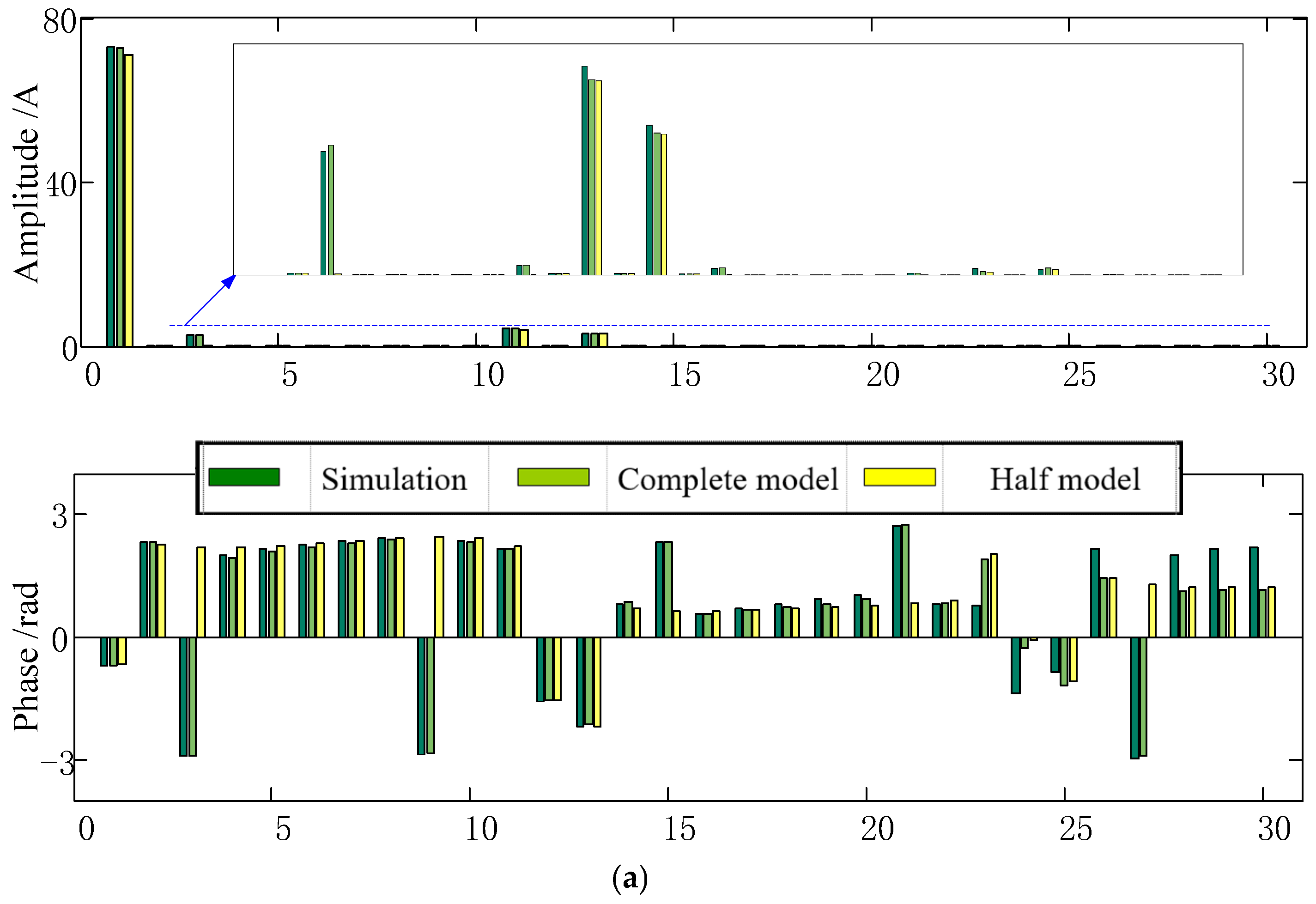
4. Simulation Verification

An electromagnetic transient model is boiled in MATLAB/SIMULINK to verify the frequency-domain harmonic model of the parallel 12-pulse rectifier proposed in this paper. The simulation parameters are shown in Table 1.
Figure 5 shows the waveforms of the AC current of the 12-pulse rectifier, ia(t), ia1(t), and ia2(t), respectively, with different parameters. The current calculated by the model proposed in this paper, which considers the influence of the negative sequence voltage (complete model), is matched with the simulation results in cases 1 and 2. However, the waveform that does not consider the influence of the negative sequence voltage (half model) is obviously different from the complete model and simulation result in case 2 (which has a bigger negative sequence). The peak value of the simulation, complete model, and half model of ia(t) of case 2 are 83.5A, 83A, and 70A, respectively.
The amplitude and phase of the harmonic current of the 12-pulse rectifier are shown in Figure 6. The current main contains 12 k ± 1th harmonic current. With the influence of negative sequence, 3rd, 9th, 15th …, the harmonic current is observed in the simulation and complete model image.
Figure 7 shows the error analysis results with case 1’s parameters, and the results of the complete model are considered the real value. It is obvious that the simplified model is much more accurate than the half model.

5. Conclusions

This paper established a frequency-domain harmonic coupled admittance matrix model of a parallel 12-pulse rectifier. This model can efficiently calculate the harmonic current produced by the rectifier under different terminal voltage conditions, including negative sequence voltage, and it has obvious accuracy advantages when the unbalanced factor of the terminal voltage is large. To adapt to different demands, a simplification model is proposed. The models proposed in this paper can be used to guide the selection and optimization of harmonic suppression measures and equipment.

Author Contributions

Conceptualization, G.Q. and Q.W.; methodology, G.Q. and Q.W.; software, G.Q. and Q.W.; validation, S.H., W.D. and N.W.; formal analysis, G.Q. and Q.W.; investigation, G.Q. and Q.W.; resources, N.Z.; data curation, S.H.; writing—original draft preparation, W.D.; writing—review and editing, N.W.; visualization, S.H.; supervision, N.Z.; project administration, G.Q.; funding acquisition, G.Q. All authors have read and agreed to the published version of the manuscript.

Funding

This research received no external funding.

Institutional Review Board Statement

Not applicable.

Informed Consent Statement

Not applicable.

Data Availability Statement

Not applicable.

Conflicts of Interest

The authors declare no conflict of interest.

References

  1. Xiao, X.; Liao, K.; Tang, S.; Fan, W. Development of Power-Electricized distribution grids and the new supraharmonics issues. Trans. China Electrotech. Soc. 2018, 33, 707–720. [Google Scholar]
  2. Zhou, X.; Chen, S.; Lu, Z. Review and prospect for power system development and related technologies: A concept of three-generation power systems. Proc. CSEE 2013, 33, 1–11. [Google Scholar]
  3. Blaabjerg, F.; Chen, Z.; Kjaer, S.B. Power electronics as efficient interface in dispersed power generation systems. IEEE Trans. Power Electron. 2004, 19, 1184–1194. [Google Scholar] [CrossRef]
  4. Wang, S.; Lv, Z.; Zhang, D.; Zhang, D. A Multi-Pulse thyristor rectifier with high power factor. Autom. Electr. Power Syst. 2012, 36, 74–78. (In Chinese) [Google Scholar]
  5. Liu, M.; Zhou, X.; Chen, H.; Xie, W.; Jing, Y.; Wang, J.; Wei, N.; Zhou, N. Analysis and calculation on harmonic amplification effect of electric vehicle charging station using three-phase uncontrolled rectification charger. Power Syst. Prot. Control 2016, 4, 36–43. (In Chinese) [Google Scholar]
  6. Leite, M.C.C.; Vieira, F.A.M.; Silva, V.B.; Fortes, M.Z.; Dias, D.H.N. Harmonic analysis of a photovoltaic systems connected to low voltage grid. IEEE Lat. Am. Trans. 2018, 16, 112–117. [Google Scholar] [CrossRef]
  7. Chen, Z.; Wang, Y.; Wen, B. Analysis and research of minimum series impedance between AC network and the AC filter in converter stations. Proc. CSEE 2017, 37, 244–250. [Google Scholar]
  8. Meng, F.; Luo, J.; Gao, L.; Yang, W.; Yang, S. A High-Power density Multi-Pulse rectifier based on harmonic reduction technology at DC link. Trans. China Electrotech. Soc. 2017, 19, 134–140. [Google Scholar]
  9. Singh, B.; Gairola, S.; Singh, B.N.; Chandra, A.; AI-Haddad, K. Multi-Pulse AC–DC converters for improving power quality: A review. IEEE Trans. Power Electron. 2008, 23, 260–281. [Google Scholar] [CrossRef]
  10. Meng, F.; Xu, X.; Gao, L. A harmonic reduction method in Multi-Pulse rectifier using passive devices. Trans. China Electrotech. Soc. 2017, 32, 77–86. [Google Scholar]
  11. Xue, Y.; Xu, Z.; Huang, Y.; Li, X. Improved time domain piecewise calculating method for AC side harmonic current of HVDC systems. Proc. CSEE 2010, 30, 96–99. (In Chinese) [Google Scholar]
  12. Sainz, L.; Balcells, J. Harmonic interaction influence due to current source shunt filters in networks supplying nonlinear loads. IEEE Trans. Power Deliv. 2012, 27, 1385–1393. [Google Scholar] [CrossRef]
  13. Malik, M.H.; Borzacchiello, D.; Chinesta, F.; Diez, P. Inclusion of frequency-dependent parameters in power transmission lines simulation using harmonic analysis and proper generalized decomposition. Int. J. Numer. Model. Electron. Netw. Devices Fields 2018, 2, e2331. [Google Scholar] [CrossRef]
  14. Zhu, Y.; Yang, S.; Meng, F. 12-pulse rectifier system with a PWM rectifier at DC side and its load adaptability. Trans. China Electrotech. Soc. 2012, 27, 85–92. [Google Scholar]
  15. Sun, Y.; Yin, Z.; Zheng, W.; Liu, Y. Study of the harmonic producing characteristics of the thyristor controlled reactors. Trans. China Electrotech. Soc. 2012, 27, 267–273. (In Chinese) [Google Scholar]
  16. Sun, Y.; Zhang, G.; Xu, W.; Mayordomo, J.G. A harmonically coupled admittance matrix model for AC/DC converters. IEEE Trans. Power Syst. 2007, 22, 1574–1582. [Google Scholar] [CrossRef]
  17. Sun, Y.; Wang, X.; Yin, Z. Non-Iterative harmonic power flow analysis for power systems with multiple harmonic sources. Proc. CSEE 2012, 32, 83–90. (In Chinese) [Google Scholar]
  18. Zhou, N.; Wei, N.; Wang, J.; Weng, L.; Wang, Q. Measurement-Based harmonic power modeling of Three-Phase uncontrolled rectification load. Proc. CSEE 2017, 37, 5583–5593. [Google Scholar]
  19. Wang, J.; Zhou, N.; Wang, Q.; Wei, N. Frequency-Domain harmonic modeling of the series 12-pulse rectifier under unbalanced voltage condition. Trans. China Electrotech. Soc. 2015, 30, 69–77. [Google Scholar]
  20. Li, Z.; Wang, G.; Li, H.; Li, X.; Fu, C. An analysis and calculation method of harmonic interaction between AC and DC system under asymmetric operation conditions. Autom. Electr. Power Syst. 2010, 34, 42–47. (In Chinese) [Google Scholar]
Figure 1. Circuits of a parallel 12-pulse rectifier: (a) equivalent circuit of a parallel 12-pulse rectifier; (b) interphase transformer (IPT) decoupled equivalent circuit of a parallel 12-pulse rectifier.
Energies 15 03946 g001
Figure 2. Harmonic analysis process of a parallel 12-pulse rectifier.
Energies 15 03946 g002
Figure 3. Positive sequence harmonic coupled admittance matrix elements of parallel 12-pulse rectifier. (a) Matrix Y+; (b) Matrix Y+∗.
Energies 15 03946 g003
Figure 4. Negative sequence harmonic coupled admittance matrix elements of parallel 12-pulse rectifier. (a) Matrix Y; (b) Matrix Y−∗.
Energies 15 03946 g004
Figure 5. Time-domain current comparison of rectifier under different conditions. (a) Case 1; (b) Case 2.
Energies 15 03946 g005aEnergies 15 03946 g005b
Figure 6. AC current harmonic spectrum of 12-pulse rectifier under different conditions. (a) Case 1; (b) Case 2.
Energies 15 03946 g006aEnergies 15 03946 g006b
Figure 7. Error analysis of models.
Energies 15 03946 g007
Table 1. Simulation parameters of 12-pulse rectifier.
CaseFire Angle αTHDu/%γOverlap Angle μ/°Ua1/VR/ΩL1,L2/HL/HH
110°1.940.138050.420.0230
230°4.790.2010°380100.50.230
Publisher’s Note: MDPI stays neutral with regard to jurisdictional claims in published maps and institutional affiliations.

