
Multi-Type Hydrocarbon Accumulation Mechanism in the Hari Sag, Yingen Ejinaqi Basin, China

1
Shaanxi Provincial Land Engineering Construction Group Co., Ltd., Xi’an 710000, China
2
School of Geoscience, China University of Petroleum (Beijing), Beijing 710069, China
3
Research Institute of Shanxi Yanchang Petroleum Corporation, Xi’an 710000, China
4
School of Human Settlement and Civil Engineering, Xi’an Jiaotong University, Xi’an 710000, China
*
Author to whom correspondence should be addressed.
Energies 2022, 15(11), 3968; https://0-doi-org.brum.beds.ac.uk/10.3390/en15113968
Submission received: 15 April 2022
/
Revised: 18 May 2022
/
Accepted: 25 May 2022
/
Published: 27 May 2022
(This article belongs to the Special Issue Shale Oil and Gas Accumulation Mechanism)
Abstract
:With the successful development of unconventional hydrocarbons, the production of unconventional hydrocarbons has increased rapidly. However, a single conventional or unconventional model is not suitable for the mechanism of hydrocarbon accumulation in a given basin or sag. Based on data from drilling, logging, and geophysical analysis, the hydrocarbon accumulation mechanism in the Hari sag in the Yingen-Ejinaqi basin, China, was analyzed. There are three sets of source rocks in the Hari sag: the K1y source rocks were evaluated as having excellent source rock potential with low thermal maturity and kerogen Type I-II1; the K1b2 source rocks were evaluated as having good source rock potential with mature to highly mature stages and kerogen Type II1-II2; and the K1b1 source rocks were evaluated as having moderate source rock potential with mature to highly mature stages and kerogen Type II1-II2. Reservoir types were found to be conventional sand reservoirs, unconventional carbonate-shale reservoirs, and volcanic rock reservoirs. There were two sets of fault-lithologic traps in the Hari sag, which conform to the intra-source continuous hydrocarbon accumulation model and the approaching-source discontinuous hydrocarbon accumulation model. The conclusions of this research provide guidance for exploring multi-type reservoirs and multi-type hydrocarbon accumulation models.
1. Introduction
With the rapid development of oil and gas exploration, unconventional hydrocarbon resources have gradually become a hotspot, especially shale oil and gas [1,2,3]. However, most unconventional reservoirs are not presented in a single mode but, rather, often in a mixed mode of unconventional and conventional reservoirs. For example, there are various reservoirs, traps, and hydrocarbon accumulation mechanisms in the Sichuan Basin and the Ordos Basin, but there are several models of hydrocarbon accumulation [4,5,6,7]. A single mode cannot meet the current need for hydrocarbon exploration and development [8,9]. Therefore, it is necessary to analyze the hydrocarbon accumulation mechanism in these areas in detail based on the actual situation.
The Yingen-Ejinaqi Basin, also known as the Yin’e Basin, is a large petroliferous basin with a relatively low level of exploration [10,11]. Oil and gas exploration in the Yin’e Basin began in 1955. Only 3.44 million tons of hydrocarbon reserves have been proven in the Chagan sag. No industrial oil flow was found in other sags. Exploration over the past 50 years has failed to achieve breakthroughs [12,13].
Researchers have carried out a series of studies on the hydrocarbon accumulation conditions in the Yin’e Basin, but the hydrocarbon accumulation mechanism has not been studied in detail [14,15,16]. The geochemical characteristics of thermal evolution, etc., have been studied by researchers, but in the Hari sag, there have been very few relevant studies on the hydrocarbon accumulation conditions [17,18,19]. In November 2015, hydrocarbon was discovered in Well Hc1. The gas flow was 9.15 × 10⁴ m3 per day, and had broken through after 60 years [20]. However, since sedimentary conditions and structural evolution are not clear in the Hari sag, the hydrocarbon accumulation conditions and mechanism need to be studied further [21].
Based on data from drilling, logging, geophysics, etc., this study systematically analyzed the source rocks, reservoirs, traps, and other conditions of hydrocarbon accumulation in the Hari sag and summarized the hydrocarbon accumulation mechanism. This research provides guidance for hydrocarbon exploration and development in the Yin’e Basin and other similar basins.
2. Geological Setting
The Yin’e Basin is located at the junction of the five plates of Kazakhstan, Junggar, Tarim, Siberia, and North China [22]. It has experienced fold basement formation, sedimentary caprock development, intraplate extension, and intracontinental orogeny [23,24]. During the evolution stage, many small depressions with similar structural development histories and that were relatively independent of each other were formed [25,26,27]. The Hari sag is a secondary structural unit of the Suhongtu Depression (Figure 1). The Hari sag covers an area of 1350 km2 and is a northeast-trending belt as a whole. Its second tectonic unit can be divided into the western slope belt, the northern depression belt, and the southern depression belt [28,29,30].
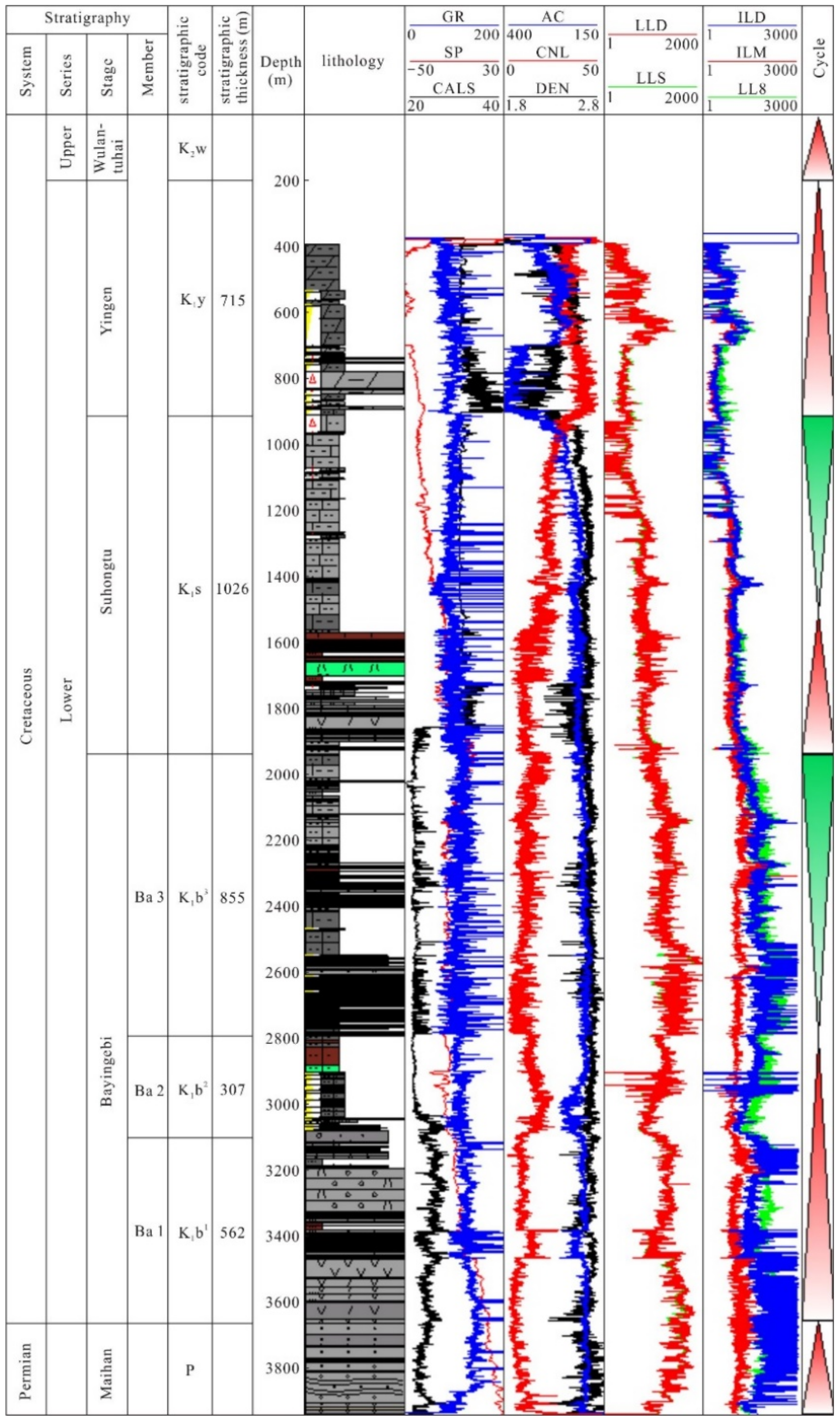
The sedimentary strata include the Carboniferous, the Permian, the Cretaceous, and the Quaternary from bottom to top (Figure 2). The focus of this study is the Cretaceous sequence, which can be divided into the Lower Cretaceous and the Upper Cretaceous. From bottom to top, the lower Cretaceous can be divided into the Bayingebi Formation (K1b), the Suhongtu Formation (K1s), and the Yingen Formation (K1y). The Upper Cretaceous only has the Wulansuhai Formation (K2w). The Bayingebi Formation includes the 1st member (K1b1), the 2nd member (K1b2), and the 3rd member (K1b3) from bottom to top. The Suhongtu Formation is divided into the 1st member (K1s1) and the 2nd member (K1s2) from bottom to top [31].
3. Data and Methods
Three-dimensional seismic data covering the whole Hari depression were provided by Shaanxi Yanchang Petroleum (Group) Co., LTD, Xi’an, China. Seismic data were collected and processed with a line spacing of 12.5 m and an intersecting line spacing of 25 m, respectively. The dominant frequency in the target layer was about 50 Hz. The vertical resolution was about 10 m, and the average speed was 2000 m/s.
Two-hundred-and-thirty-four Lower Cretaceous rock samples were collected from ten wells in the Hari depression (Figure 1). Based on these samples, various analytical measurements were performed, including pyrolysis, extraction, and quantification of total organic carbon (TOC) and soluble organic matter; determination of the whole rock; organic microscopic composition; and vitrinite reflectance (Ro%).
All rock samples were cleaned prior to crushing and pulverization. The TOC and the Rock-Eval pyrolysis of samples were analyzed. The parameter S1 is the amount of free hydrocarbon that can be volatilized from the rock sample. S2 is the amount of hydrocarbon produced by the cracking of organic matter in rocks. The hydrogen index (S2/TOC × 100) is an effective indicator of kerogen type.
Organic geochemical tests were carried out on lower Cretaceous coal measure source rock samples and oil and gas samples from key wells, including carbon isotope analysis of crude oil and gas and gas chromatography–mass spectrometry (GC-MS) analysis of source rocks and crude oil.
To ensure the accuracy of these tests, the China University of Petroleum and Shanxi Yanchang Petroleum Company jointly conducted these tests.
4. Results
4.1. Source Rock Characteristics
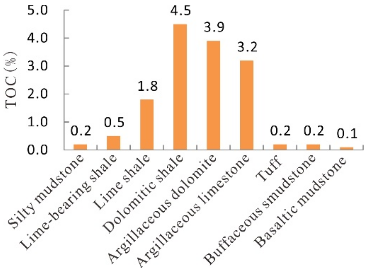
The source rock strata (Yingen Formation and Bayingebi Formation) in the Hari sag are mainly semi-deep and deep lacustrine facies. Source rocks are mainly shale and carbonate rocks. Among these, carbonate-shale had the highest organic matter abundance (Figure 3).
The average TOCs in K1y, K1b2, and K1b1 were 3.98, 1.18 and 0.89%, respectively, while the average values of source rock potential S1 + S2 were 22.24 mg/g, 7.85 mg/g, and 4.63 mg/g, respectively. According to the organic matter evaluation criteria of terrestrial source rocks, the source rocks in K1y were evaluated as excellent source rocks, the source rocks in K1b2 were evaluated as good to excellent source rocks, and the source rocks in K1b1 were evaluated as medium to good sources rocks (Table 1).
Using rock pyrolysis parameters (“A” group composition, n-alkane composition, and sterane composition) and other kerogen-type parameters and indicators, combined with source rock maturity parameters, the main source rocks in the Hari sag were evaluated (Table 2, Table 3 and Table 4).
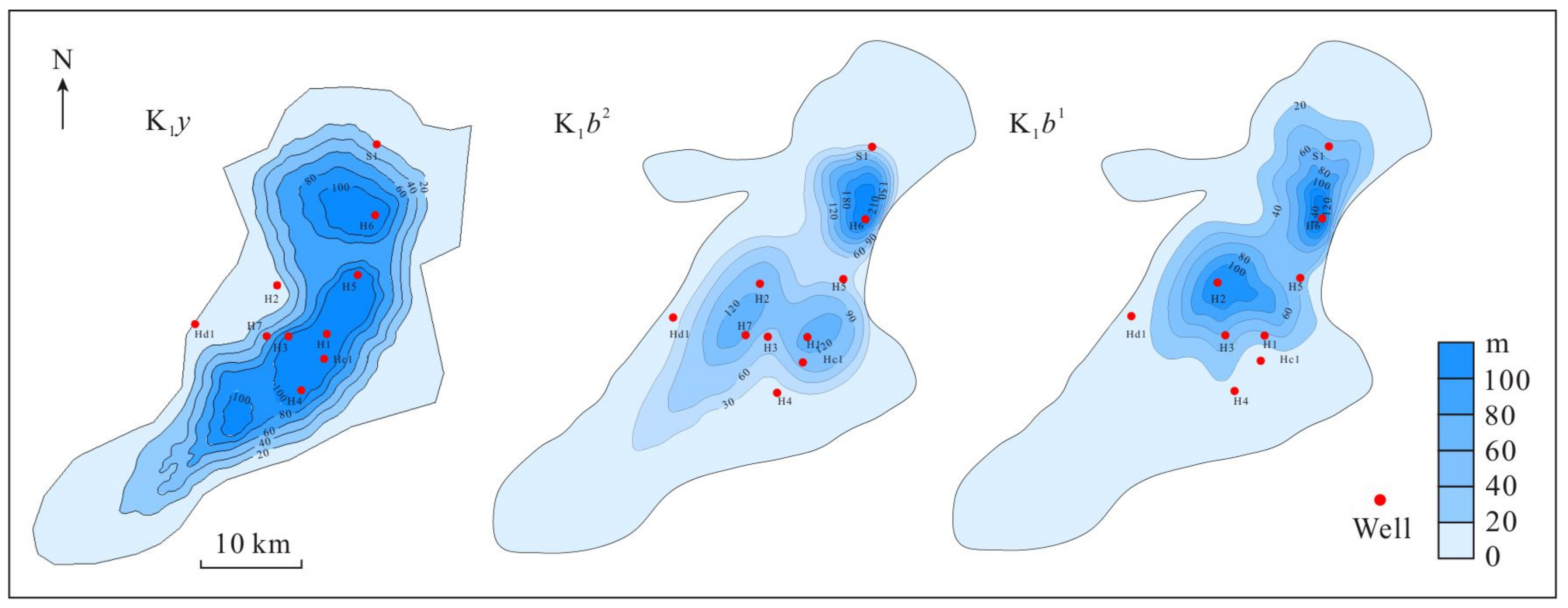
In this research, the effective source rock was defined. The criteria included the thickness of a single layer being more than 1 m; the lithology being dark shale, limestone, or dolomite, etc.; a TOC > 0.6%, an S1 + S2 > 2 mg/g, an Ro > 0.7%, and a Tmax > 440 °C. According to the identification of and statistics from effective source rocks in wells, a contour map of effective source rock thickness in the Hari sag was drawn and combined with the seismic tracking and the identification of the effective source rocks (Figure 4), as follows:
K1y: Effective source rocks are distributed widely in the Hari sag. The thickness in the north is up to 151 m. The thickest is in the south and is up to 583.8 m (Figure 4).
K1b2: Effective source rocks are distributed partly in the northern Hari sag. The thickness is up to 222 m (Figure 4).
K1b1: The distribution area of the effective source rocks is smaller than that of the two formations above and is closer to the north. The thickness is up to 151 m (Figure 4).
4.2. Reservoir Characteristics
4.2.1. Depositional Environment of Reservoirs
The Cretaceous in the Yin’e Basin experienced three stages. During the deposition period of the Bayingebi formation, the tectonic activity was relatively strong. Under the action of extensional stress, small fault depressions were formed dispersedly. Due to the large depth, the sedimentary system was dominated by coarse clastic alluvial fans and fan deltas, so coarse clastic deposits basically covered the bottom of the sags in the initial stage. With the enhancement of stretching, the sag range was expanded, and the sediment migrated to the shoreline. The coarse clastic deposits appeared to be regressive, and a set of dark shale of the semi-deep lake and the deep lake developed in the deep area of the sag. By the end of this period, the lake level declined. The coarse clastic deposition system extended into the center of the sag, the coverage area increased, and the depositional area was mostly covered by shallow lake deposits.
Entering the period of the Suhongtu Formation, the tectonic activity inherited the state of the previous period and weakened slightly. The sags continued to fall simultaneously, and the source supply was sufficient. In the early stage, the lake area shrank slightly, affected by the slope, and was dominated by coarse clastic deposits. However, affected by the filling of previous deposits, the structural slope slowed down, the alluvial fans gradually transitioned to fan deltas, and the deposits were dominated by a conglomerate, evolving into a state where conglomerate and sandstone coexisted. In the late period, the lake level was maintained at a certain depth, and the source advancement range was limited. During this period, due to strong volcanic activity, volcanic rock intrusions existed in some areas.
With the continuous weakening of tectonic activities, the continuous expansion of the sag, and a continuous increase in the lake area, the lake level range reached its maximum value in the late Early Cretaceous. Many sets of fan delta sedimentary systems developed along the controlling faults of the sag. Since the source might have been rich in calcium or magnesium, the content of carbonate minerals in shale was relatively high (this phenomenon can be seen in the Lower Cretaceous). In the K1y period, due to sag shape, lake level, source, etc., local areas developed dolomite and gypsum deposits.
4.2.2. Reservoir Quality
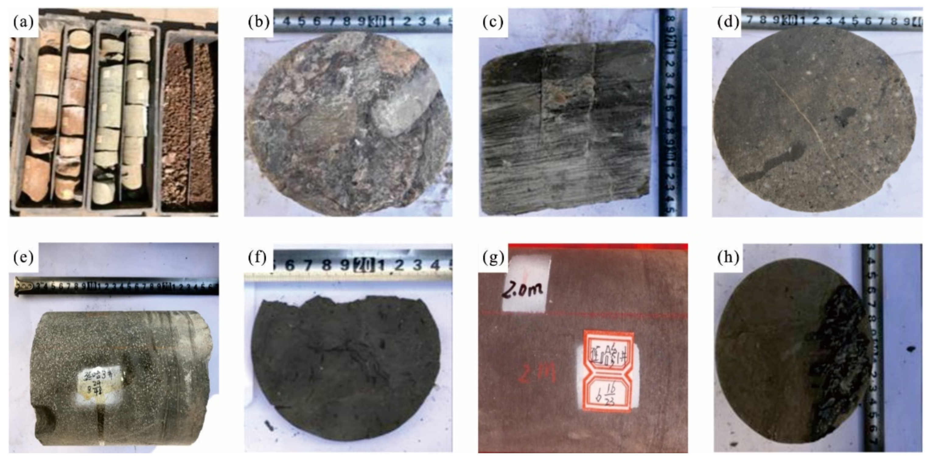
Based on the complex tectonic background and the composition of the sedimentary system, the Hari sag of the Yin’e Basin has formed various types of reservoirs. These reservoirs can be classified into the following four types: (1) clastic reservoirs (sandstone, conglomerate), (2) limestone-related reservoirs, (3) dolomite-related reservoirs, and (4) volcanic rock reservoirs (Figure 5). These reservoir types were the important basis for hydrocarbon accumulation in the Hari sag.
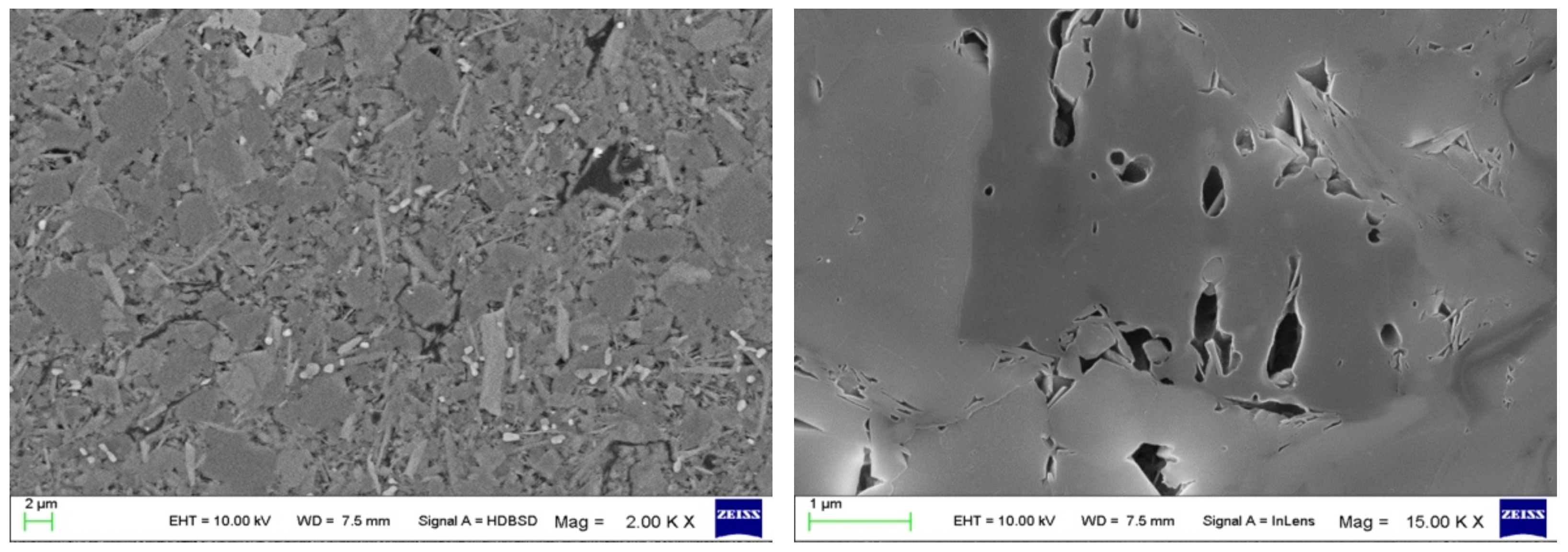
Conventional sand and conglomerate reservoirs: During the Cretaceous, sand and conglomerate reservoirs were mainly developed in alluvial fans and fan delta facies on the slopes of the sags. The sediment thickness of the steep slopes is significantly greater than that of the trough and gentle slopes. The average thickness of the reservoir is 770 m. During the Upper Paleozoic, due to the development of marine deposits, the conventional reservoir was mainly delta deposits with an abundant source supply. The average thickness of the reservoir is now 202 m. The reservoir spaces of sand and the conglomerate reservoirs are generally underdeveloped, and they are dominated by intragranular dissolution pores and intergranular dissolution pores, with a small number of primary pores and fracture pores (Figure 6). The Bayingebi formation has a low average porosity of 4.55% and a low average permeability of 0.48 mD. The physical properties of the sandstone of the Suhongtu formation are even lower (Table 5).
Unconventional calcareous shale reservoirs: These reservoirs are mainly semi-deep and deep lake facies or shallow sea shelf facies, and their thickness is much greater than that of the sediments in the lake margin. Carbonates and clastic rocks coexist, and through cementation or metagenesis, carbonate-shale reservoirs have formed. Tectonic activities and hydrodynamic forces in these reservoirs resulted in the formation of dissolution pore-fracture storage spaces. The average thickness of the lime-shale reservoir is 607 m. The porosity of the K1b lime-shale reservoir is in the range of 0.3–13.59%, with an average of 7.63%, and the permeability is mainly distributed between 0.01 and 1.65 mD, with an average of 0.74 mD. The average thickness of the dolomitic-shale reservoir is 151 m. The porosity of the K1y dolomitic-shale is mainly distributed in the range of 0–15%, and the average is 6.73% (Table 5).
Volcanic rock reservoirs: the distribution of these reservoirs is relatively limited. The volcanic rock reservoirs have an average thickness of 95 m, and their pores are dominated by primary almond pores, with dissolution pores and high-angle fractures, which make up the main gas storage space of volcanic gas reservoirs. The porosity of the K1b volcanic reservoir is 0.88–10.18%, with an average of 4.76%, and the permeability is mainly distributed between 0.01 and 2.36 mD, with an average of 0.19 mD (Table 5).
These four reservoirs are all of ultra-low porosity and ultra-low permeability. Among them, sand, conglomerate, and lime-shale reservoirs have the best physical properties and have a greater thickness than dolomite reservoirs and volcanic rock reservoirs (Table 5). This finding corresponds with the current discovery of major oil reservoirs, which are mainly concentrated in conventional sand and conglomerate reservoirs and in unconventional carbonate-shale reservoirs. It shows that the physical properties of a reservoir have a certain control effect on oil and gas reservoirs.
4.3. Fault-Lithologic Trap Characteristics
According to the results of the drilling and hydrocarbon tests, there are mainly two sets of hydrocarbon reservoirs in the Hari sag, which are the unconventional hydrocarbon reservoirs in K1b2 and the top sandstone hydrocarbon reservoirs in K1b1. Thick source rocks with high thermal maturity and good oil generation conditions have developed in K1b2. In addition, carbonate-shale fractured reservoirs have developed in this formation, and gas was found in this formation, which is the most favorable unconventional reservoir in this area.
This section has developed fan delta and alluvial fan facies, which can be used as an effective lithologic reservoir, and thick shale, which can be used as an effective cap rock. Therefore, K1b2 can form a self-generating and self-storing hydrocarbon reservoir, which is the most favorable hydrocarbon reservoir assemblage. Sandstone has developed at the top of K1b1, which has certain reservoir conditions and is close to the high-quality source rocks in K1b2. This is a favorable gas-bearing formation. Therefore, the fault-lithologic traps are mainly sandstone traps in K1b1 and shale traps in K1b2.
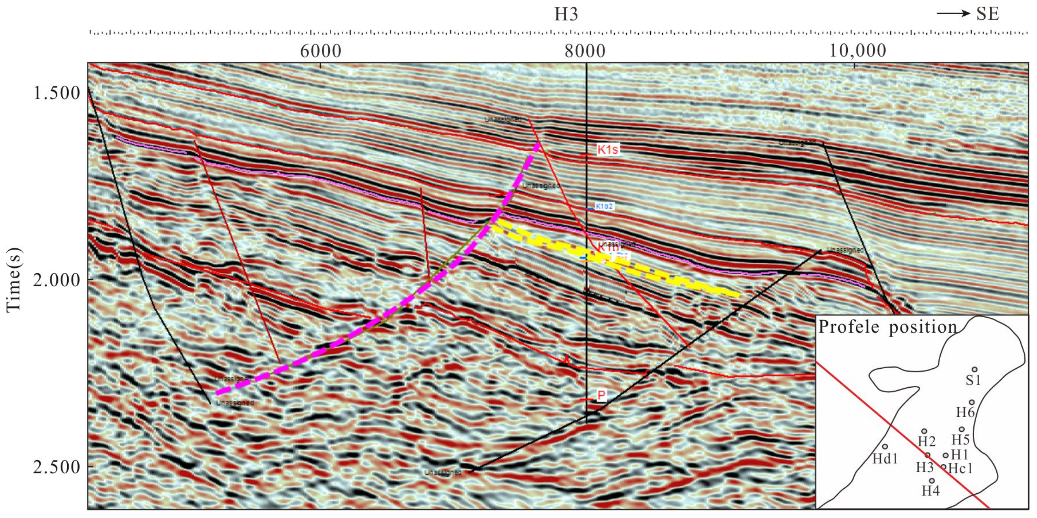
The sandstone fault-lithologic traps in K1b1 are mainly at Well H3, as shown in Figure 7. According to the results of drilling and previous reservoir predictions, the Hari sag belongs to an extremely weak hydrostatic deposition with very limited sandstone. According to data from Well H3, in the early stages of K1b1, the rapid accumulation of alluvial fan deposits was the main mechanism of deposition in the Hari sag, and these deposits did not easily accumulate hydrocarbon due to their poor physical properties. However, at the end of K1b1, a small fine-grained sand body of fan delta deposits was formed in the downward direction of faults or slope break belts. This kind of sand body could easily develop fault-lithologic traps. The quality of physical properties and the matching relationship with source rocks controlled hydrocarbon accumulation in these fault-lithologic traps.
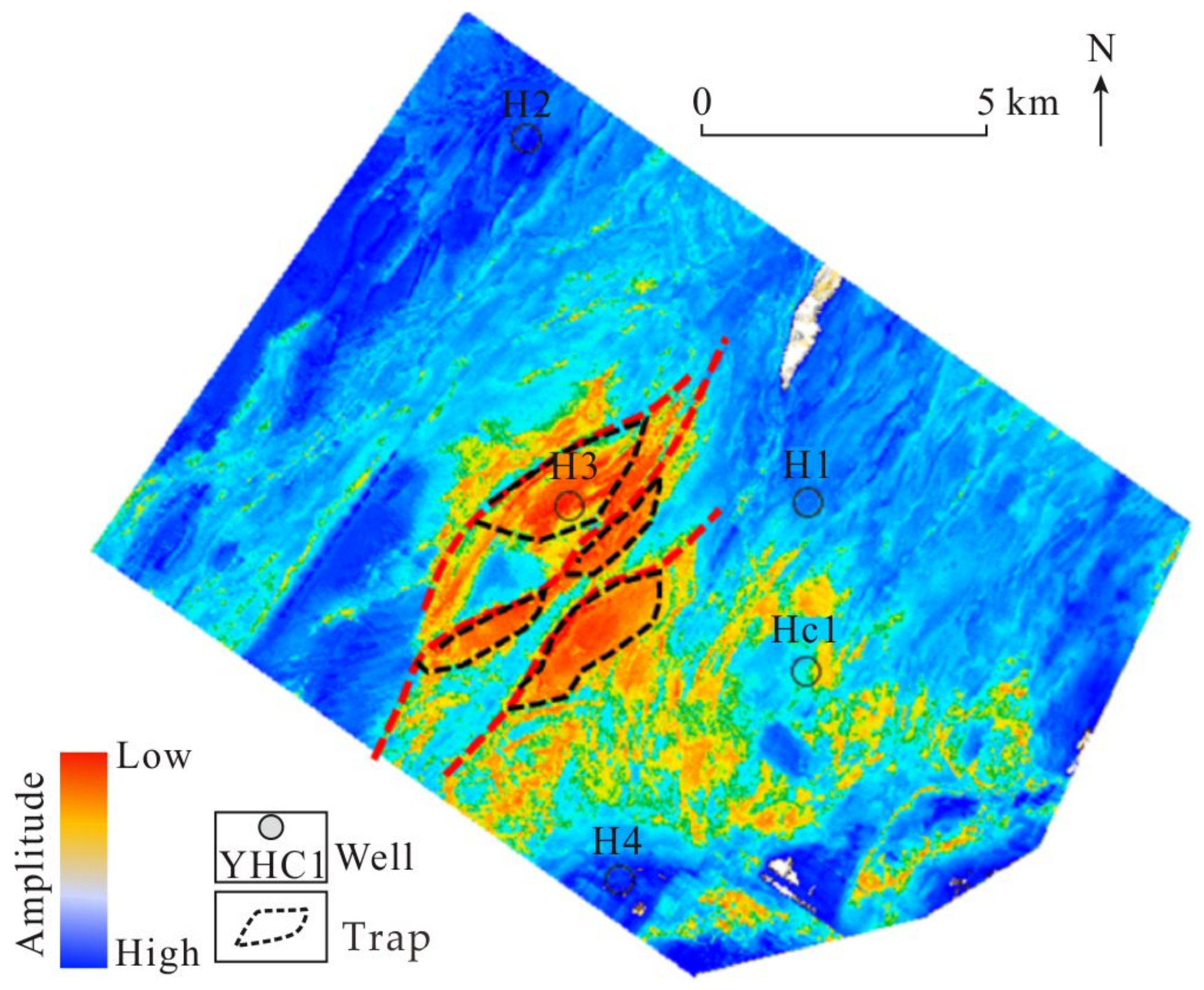
It can be seen from the three-dimensional seismic plane figure of K1b1 in the Hari sag that the sandstone area is relatively small and concentrated and is mainly distributed in Well H3 in its southern part (Figure 8). It is located in the relatively large dip direction of the slope break belt. A total of four small sandstone fault-lithologic traps were found in the 3D seismic area of the Hari sag, and their area is 3.8 km2 (Figure 8).
Hydrocarbon accumulation in K1b1 is mainly controlled by lithology. The lithologic oil-bearing reservoir is mainly carbonate-shale with micro-fractures and several dissolution pores, which are the main reservoir space. According to the results of drilling, sets of unconventional reservoirs are widely distributed in the sag. The distribution range is wide from Well H2 to Well Hs1. However, the reservoir quality is mainly controlled by dissolution pores and micro-fractures. Therefore, the favorable development area of such fault-lithologic traps is near the bottom of volcanic activity or the deep fault. Vertically, there is a large set of shales on the roof, and there is shale and tight sandstone on the floor. Horizontally, this is blocked by physical properties, forming multiple sweet spots.
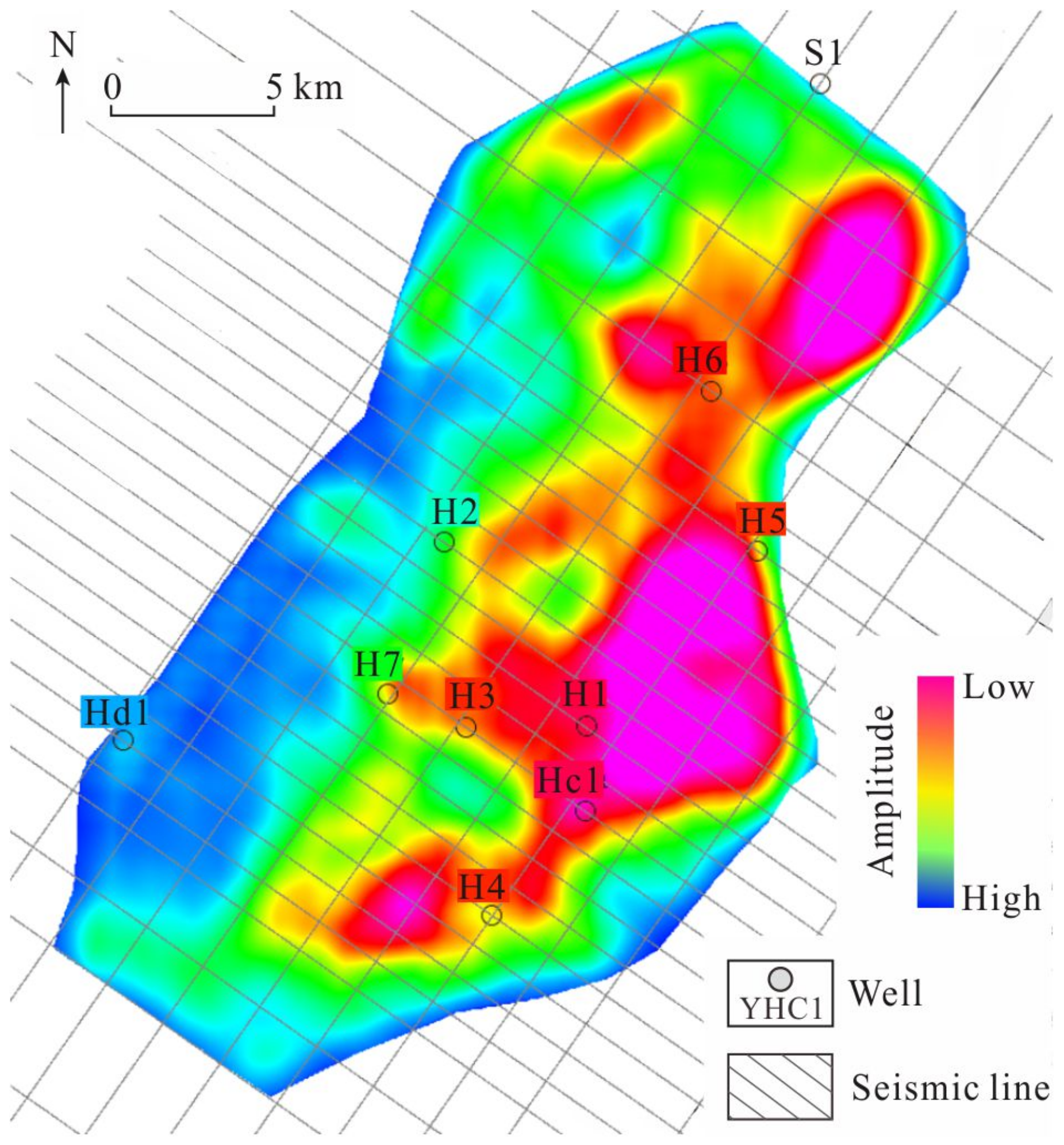
According to the prediction diagram of the K1b2 unconventional reservoir in the Hari sag, the unconventional reservoirs in K1b2 are mainly distributed along two sub-sags in the north and south and gradually decrease from the center of the sag to the slope area (Figure 9). The area of favorable fault-lithologic traps is 99.88 km2. A good contiguous distribution has formed in the south sag from Well Hs1 to Well H5. The physical properties in this area have been mainly affected by faults and volcanic activities in Well Hs1 and Well H5. The other relatively good distribution area is located around Well H6, belonging to the northern sub-sag of the Hari sag.
5. Discussion
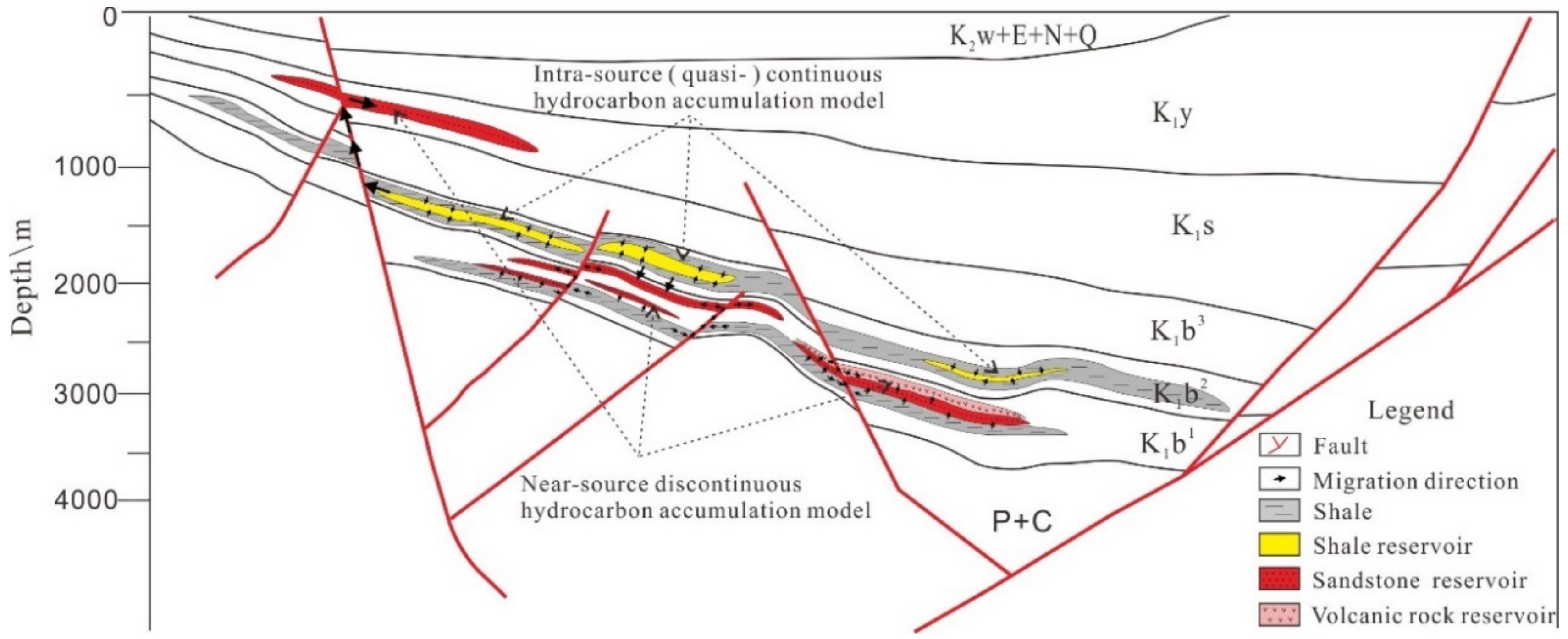
With the progress of hydrocarbon exploration and development, a single conventional or unconventional model has been unable to explain the mechanism of oil and gas charging and accumulation in the same basin or sag [32,33,34,35,36]. In practice, multiple modes are often developed [37,38,39,40]. For example, there are various types of hydrocarbon reservoirs in the Hari sag, including carbonate-shale reservoirs, conventional sandstone reservoirs, and volcanic rock reservoirs. The reservoir spaces are mainly fractured and dissolution pores. According to structural position, oil and gas are distributed in the central sag and slope zone. According to the trap type, the types of oil and gas reservoirs in the Hari sag are mainly fault-lithologic combination reservoirs, followed by fault-block reservoirs. In a word, the hydrocarbon accumulation models in the Hari sag can be divided into two types: the intra-source continuous hydrocarbon accumulation model and the approaching-source discontinuous hydrocarbon accumulation model (Figure 10).
5.1. Intra-Source Continuous Hydrocarbon Accumulation Model
The intra-source continuous hydrocarbon accumulation model refers to hydrocarbon accumulation inside source rocks. These source rocks (shales) are also reservoirs. Due to the high charging pressure during hydrocarbon generation, hydrocarbon migrates into the fracture and dissolution pores of the shales.
During the early Cretaceous, rapid subsidence of the Hari sag occurred. In the deposition period of K1b and K1y, a faulted basin developed rapidly, the lake level rose as a whole, and the range of the lake basin was also expanding. Most of the deposition period occurred in a warm, humid and fresh environment. Under the background of an insufficient source supply and a subsidence rate that was greater than the sedimentation rate, many sets of carbonate-shales, dolomitic-shales, and tuffaceous shales were deposited in the sag, and sandstone was rare. In the late rapid burial process, organic matter in the K1b shale reached the mature to high mature stage, and the transformation of the source rocks was accelerated by widely developed magmatic rocks. This provided the material foundations for the gas reservoirs.
During late tectonic activity, diagenetic evolution, and a hydrocarbon generation process, various types of micro-pores and micro-fractures were developed in shale source rocks, providing a good foundation for hydrocarbon accumulation through self-generation and self-storage.
Consequently, the lack of effective dredging has ensured there is local hydrocarbon enrichment in the Hari sag. The hydrocarbon accumulation system in source rocks has formed through the filling of primary pores, fractures, the dissolution of pores freely, and the adsorption of mineral particles. These have become self-generating and self-storage natural gas reservoirs inside the source rocks.
5.2. Approaching-Source Discontinuous Hydrocarbon Accumulation Model
The approaching-source discontinuous hydrocarbon accumulation model refers to hydrocarbon accumulation from source rocks into near sandstone. The reservoirs are fine sandstone, siltstone, and andesite. The sandstone is not developed generally in the depression area, but there are still thin sandstone reservoirs in some areas of the slope belt. Although these sandstone reservoirs are characterized by small-scale and poor physical properties, they can be used as effective reservoirs due to a sufficient hydrocarbon supply around the sandstone.
Volcanic gas reservoirs are mainly distributed in the volcanic rock development section at the bottom of K1b. Due to frequent volcanic activities in the early Cretaceous, volcanic dissolution pores have developed, which provide good reservoir spaces for oil and gas. Volcanic reservoirs are close to the effective source rocks in K1b, and the source rocks have entered the stage of hydrocarbon generation and expulsion. Therefore, they conform to the approaching-source discontinuous hydrocarbon accumulation model.
The approaching-source discontinuous hydrocarbon accumulation model has these main characteristics: (1) it is adjacent to the effective source rock section; (2) oil and gas can be accumulated in structure traps or in sandstone lithologic traps; and (3) oil and gas reservoirs can be formed in an independent volcanic trap.
6. Conclusions
- (1)
- The source rocks of the Hari sag have mainly developed in K1b1, K1b2, and K1y. The source rocks in K1b1 are characterized by a medium abundance of organic matter, high thermal maturity, and kerogen Type II1-II2. The source rocks in K1b2 are characterized by a high abundance of organic matter, high thermal maturity, and kerogen Type II1-II2. The source rocks in K1y are characterized by a high abundance of organic matter, low thermal maturity, and kerogen Type I-II1.
- (2)
- A conventional sandstone (conglomerate) reservoir, an unconventional carbonate-shale reservoir, and a volcanic reservoir have developed in the Hari sag. Among these, the physical properties of sand, the conglomerate reservoir, and the lime-shale reservoir are the best, followed by the dolomite reservoir and the volcanic rock reservoir. At present, hydrocarbon has mainly accumulated in the sand, the conglomerate reservoir, and the lime-shale reservoir.
- (3)
- The main trap types in the Hari sag are fault-lithologic traps, which are sandstone fault-lithologic traps in K1b1 and shale fault-lithologic traps in K1b2.
- (4)
- The hydrocarbon accumulation model of the Hari sag can be divided into two types: the intra-source continuous hydrocarbon accumulation model and the approaching-source discontinuous hydrocarbon accumulation model.
Author Contributions
Conceptualization, B.P. and T.C.; methodology, L.Z.; software, J.L.; validation, J.L. and B.P.; formal analysis, Z.Z.; resources, T.C.; data curation, T.C.; writing—original draft preparation, B.P.; writing—review and editing, T.C.; visualization, L.Z.; supervision, L.Z.; project administration, T.C.; funding acquisition, T.C. All authors have read and agreed to the published version of the manuscript.
Funding
This research was funded by the Technology Innovation Center for Land Engineering and Human Settlements, Shaanxi Land Engineering Construction Group Co., Ltd., and Xi’an Jiaotong University, grant number 2021WHZ0090; the project of Shaanxi Provence Land Engineering Construction Group, grant number DJNY2021-17; and the Natural Science Basic Research Program of Shaanxi, grant number 2020JQ-1002.
Institutional Review Board Statement
Not applicable.
Informed Consent Statement
Not applicable.
Data Availability Statement
Not applicable.
Conflicts of Interest
The authors declare no conflict of interest.
References
- Zha, X.; Lai, F.; Gao, X.; Gao, Y.; Jiang, N.; Luo, L.; Li, Y.; Wang, J.; Peng, S.; Luo, X.; et al. Characteristics and Genetic Mechanism of Pore Throat Structure of Shale Oil Reservoir in Saline Lake—A Case Study of Shale Oil of the Lucaogou Formation in Jimsar Sag, Junggar Basin. Energies 2021, 14, 8450. [Google Scholar] [CrossRef]
- Breyer, J.A. Shale Reservoirs: Giant Resources for the 21st Century; AAPG Memoir; American Association of Petroleum Geologists: Tulsa, OK, USA, 2012; Volume 97, pp. 1–451. [Google Scholar]
- Huo, Z.; Hao, S.; Liu, B.; Zhang, J.; Ding, J.; Tang, X.; Li, C.; Yu, X. Geochemical characteristics and hydrocarbon expulsion of source rocks in the first member of the Qingshankou Formation in the Qijia-Gulong Sag, Songliao Basin, Northeast China: Evaluation of shale oil resource potential. Energy Sci. Eng. 2020, 8, 1450–1467. [Google Scholar] [CrossRef]
- Liu, S.; Deng, B.; Jansa, L.; Li, Z.; Sun, W.; Wang, G.; Luo, Z.; Yong, Z. Multi-Stage Basin Development and Hydrocarbon Accumulations: A Review of the Sichuan Basin at Eastern Margin of the Tibetan Plateau. J. Earth Sci. 2017, 29, 307–325. [Google Scholar] [CrossRef]
- Wang, R.; Liu, K.; Shi, W.; Qin, S.; Zhang, W.; Qi, R.; Xu, L. Reservoir Densification, Pressure Evolution, and Natural Gas Accumulation in the Upper Paleozoic Tight Sandstones in the North Ordos Basin, China. Energies 2022, 15, 1990. [Google Scholar] [CrossRef]
- Lis-´Sledziona, A.; Kaczmarczyk-Kuszpit, W. A Technique of Hydrocarbon Potential Evaluation in Low Resistivity Gas-Saturated Mudstone Horizons in Miocene Deposits, South Poland. Energies 2022, 15, 1890. [Google Scholar] [CrossRef]
- Wang, X.; Zhou, X.; Li, S.; Zhang, N.; Ji, L.; Lu, H. Mechanism Study of Hydrocarbon Differential Distribution Controlled by the Activity of Growing Faults in Faulted Basins: Case Study of Paleogene in the Wang Guantun Area, Bohai Bay Basin, China. Lithosphere 2022, 2021, 7115985. [Google Scholar] [CrossRef]
- Wojnicki, M.; Luba´s, J.; Gawronski, M.; Szuflita, S.; Kusnierczyk, J.; Warnecki, M. An Experimental Investigation of WAG Injection in a Carbonate Reservoir and Prediction of the Recovery Factor Using Genetic Programming. Energies 2022, 15, 2127. [Google Scholar] [CrossRef]
- Lyu, C.; Wang, X.; Lu, X.; Zhou, Q.; Zhang, Y.; Sun, Z.; Xiao, L.; Liu, X. Evaluation of Hydrocarbon Generation Using Struc-tural and Thermal Modeling in the Thrust Belt of Kuqa Foreland Basin, NW China. Geofluids 2020, 2020, 8894030. [Google Scholar] [CrossRef]
- Wu, M.; Wang, X. Geological characteristics of oil & gas exploration in the Yingen-Ejin Basin. China Pet. Explor. 2003, 8, 53–57. [Google Scholar]
- Jin, G. Study on the Formation and Evolution of the Basin in Neopaleozoic in Area of Yin’gen-Eji’naqi; Chang’an University: Xi’An, China, 2010. [Google Scholar]
- Hou, Y.; Wang, H.; Fan, T.; Zhang, H.; Yang, R.; Li, Y.; Long, S. Sedimentary Characteristics and Stratigraphic Age of the Thick-Bedded Coarse Clastic Rocks in the Yingen-Ejin Banner Basin, Northern China. Acta Sedimentol. Sin. 2018, 36, 45–59. [Google Scholar]
- Zhijun, C.; Fangxia, M.; Gang, X.; Yong, Z.; Yiwen, G.; Xiaoduo, W.; Changchun, H. Oil-sources rock correlation of Bayingebi Formation in Hari sag, Yingen-Ejinaqi Basin. Oil Gas Geol. 2019, 40, 900–916. [Google Scholar]
- Liu, J.; Luo, X.; Li, H.; Li, X. Geochemical characteristics of hydrocarbon source rocks of the Lower Cretaceous in the Chagan Sag. Lithol. Reserv. 2013, 25, 75–80. [Google Scholar]
- Yang, G.; Jiao, D.; Xiao, B.; Mingquan, C.; Jianjun, L.; Yanli, W. Tectono-sequence-sedimentary characteristics, basin prototypes and their genetic mechanisms in Chagan sag of Yin-E Basin, Inner Mongolia. J. Palaeogeogr. 2013, 15, 305–316. [Google Scholar]
- Fang, Q.; Guo, D.; Xu, H. Volcanic Reservoir Characteristics of the Suhongtu Formation in The Chagan Sag, Yin-E Basin. J. Stratigr. 2014, 38, 454–460. [Google Scholar]
- Ye, J.; Yang, X. Characteristics of The Temperature and Pressure Fields in Chagan Sag of Yingen-Ejina Banner Basin. Nat. Gas Ind. 2003, 34, 31–35. [Google Scholar]
- Zuo, Y.H.; Ma, W.M.; Deng, Y.X.; Hao, Q.Q.; Li, X.J.; Guo, J.M.; Nan, Q.; Wang, L.R. Mesozoic and Cenozoic Thermal History and Source Rock Thermal Evolution History in the Chagan Sag, Inner Mongolia. Earth Sci. J. China Univ. Geosci. 2013, 38, 116–123. [Google Scholar]
- Wang, X.; Yu, S.; Li, S.; Zhang, N. Two parameter optimization methods of multi-point geostatistics. J. Pet. Sci. Eng. 2021, 208, 109724. [Google Scholar] [CrossRef]
- Zhao, C.; Liu, H.; Ren, L.; Chen, Z.; Li, K.; Bai, X.; Wang, X. Geological environment and prospective significance of Cretaceous gas reservoir in Well YHC1 of Yin’e Basin. Nat. Gas Geosci. 2017, 28, 439–451. [Google Scholar]
- Chen, Z.; Gao, Y.; Liu, H.; He, Y.; Ma, F.; Meng, J.; Zhao, C.; Han, C. Geochemical characteristics of Lower Cretaceous source rocks and oil-source correlation in Hari sag. Acta Pet. Sin. 2018, 208, 109724. [Google Scholar]
- Zhong, F.; Zhong, J.; Wang, Y.; You, W. Geochemistry Characteristics and Origin of Early Cretaceous Volcanic Rocks in Suhongtu Depression. Acta Mineral. Sin. 2014, 34, 107–116. [Google Scholar]
- Chen, Z.; Ren, Z.; Cui, J.; Qi, K.; Zhang, Y.; Yu, C.; Ren, W.; Yang, G.; Liu, R. Age and petroleum geological implications of prolific formations in Ha’ri Depression Well YHC1, Yin’e Basin. Oil Gas Geol. 2019, 40, 144–158. [Google Scholar]
- Wei, S.; Zhang, H.; Lin, W.; Li, A. Exploration Prospects for Oil and Gas in Yingen-Ejinaqi Basin. Nat. Gas Ind. 2005, 25, 7–10. [Google Scholar]
- Guo, Y.; Wang, X.; Liu, W. Characteristic of Hydrocarbon System and Exploration Prospect of Yingen-Ejina Banner Basin. Pet. Geol. Oilfield Dev. Daqing 2000, 19, 4–8. [Google Scholar]
- Yang, P.; Ren, Z.; Xia, B.; Tian, T.; Zhang, Y.; Qi, K.; Ren, W. Tectono-Thermal Evolution, Hydrocarbon Filling and Accumulation Phases of the Hari Sag, in the Yingen-Ejinaqi Basin Inner Mongolia, Northern China. Acta Geol. Sin. -Engl. Ed. 2018, 92, 1157–1169. [Google Scholar] [CrossRef]
- Wang, X.; Ren, L.; Liu, H.; Chen, Z.; Bai, X.; Zhao, C.; Song, J. Characteristics and resource potential analysis of the Lower Cretaceous source rocks in the Hari Sag. J. Xi’an Univ. Sci. Technol. 2019, 39, 286–293. [Google Scholar]
- Yan, K.; Zuo, Y.; Yang, M.; Zhou, Y.; Zhang, Y.; Zheng, Z. Pyrolysis experiment and hydrocarbon generation potential of the Bayingebi 2 Formation in the Hari Sag, Yingen-Ejiqi Basin, China. Arab. J. Geosci. 2021, 14, 25–36. [Google Scholar] [CrossRef]
- Chen, Z.J.; Ren, L.Y.; Liu, H.C.; Gao, Y.W.; Wang, B.J. Application of Geophysical Method to Prediction and Evaluation of Hydrocarbon Source Rocks in Hari Depression. Pet. Geol. Eng. 2016, 30, 30–35. [Google Scholar]
- Xing, G.; Qi, K.; Ren, Z.; Cui, J.; Zhang, Y.; Yang, G. Diagenesis and hydrocarbon charging period in the Lower Cretaceous Bayingebi Formation, Hari sag, Yin’E Basin, Northern China. Pet. Sci. Technol. 2022, 41, 1091–6466. [Google Scholar] [CrossRef]
- Jia, C.; Pang, X.; Song, Y. The mechanism of unconventional hydrocarbon formation: Hydrocarbon self-sealing and intermolecular forces. Pet. Explor. Dev. 2021, 48, 507–526. [Google Scholar] [CrossRef]
- Zhao, X.Z.; Zhang, L.P.; Jin, F.M.; Wang, Q.; Bai, G.P.; Li, Z.Y.; Wang, J. Hydrocarbon charging and accumulation history in the niudong buried hill field in the baxian depression, eastern china. Mar. Pet. Geol. 2017, 88, 343–358. [Google Scholar] [CrossRef]
- Hao, Y.; Zhou, J.G.; Zhang, J.Y.; Ni, C.; Gu, M.F.; Xin, Y.G. Characteristics and controlling factors of dolomite reservoir of Middle Permian Qixia Formation in northwest Sichuan Basin. Sediment. Geol. Tethyan Geol. 2013, 33, 68–74. [Google Scholar]
- Ma, Y.S.; Guo, T.L.; Zhao, X.F.; Cai, X.Y. Formation mechanism of deep high-quality dolomite reservoir in Puguang Gasfield. Sci. Sin. 2007, 37, 43–52. [Google Scholar]
- Davies, G.R.; Smith, L.B. Structurally controlled hydrothermal dolomite reservoir facies: An overview. AAPG Bull. 2006, 90, 1641–1690. [Google Scholar] [CrossRef]
- Ali, M.Y. Carbonate cement stratigraphy and timing of diagenesis in a Miocene mixed carbonate-clastic sequence, offshore Sabah, Malaysia: Constraints from cathodoluminescence, geochemistry, and isotope studies. Sediment. Geol. 1995, 99, 191–214. [Google Scholar]
- He, W.; Liu, Y.; Wang, D.; Lei, D.; Liu, G.; Gao, G.; Huang, L.; Qi, Y. Geochemical Characteristics and Process of Hydrocarbon Generation Evolution of the Lucaogou Formation Shale, Jimsar Depression, Junggar Basin. Energies 2022, 15, 2331. [Google Scholar] [CrossRef]
- Wang, X.; Liu, Y.; Hou, J.; Li, S.; Kang, Q.; Sun, S.; Ji, L.; Sun, J.; Ma, R. The relationship between synsedimentary fault activity and reservoir quality — A case study of the Ek1 formation in the Wang Guantun area, China. Interpretation 2020, 8, sm15–sm24. [Google Scholar] [CrossRef]
- Hatem, B.A.; Abdullah, W.H.; Hakimi, M.H.; Mustapha, K.A. Origin of organic matter and paleoenvironment conditions of the Late Jurassic organic-rich shales from Shabwah sub-basin (western Yemen): Constraints from petrology and biological markers. Mar. Pet. Geol. 2016, 72, 83–97. [Google Scholar] [CrossRef]
- Wang, X.; Zhang, F.; Li, S.; Dou, L.; Liu, Y.; Ren, X.; Chen, D.; Zhao, W. The Architectural Surfaces Characteristics of Sandy Braided River Reservoirs, Case Study in Gudong Oil Field, China. Geofluids 2021, 2021, 1–12. [Google Scholar] [CrossRef]
Figure 1.
Tectonic location of Yin’e basin (a), tectonic location of the Hari sag (b), and well distribution (c) in the Hari sag.
Figure 1.
Tectonic location of Yin’e basin (a), tectonic location of the Hari sag (b), and well distribution (c) in the Hari sag.

Figure 2.
Comprehensive histogram of strata in the Hari sag.

Figure 3.
Relationship between lithology and organic matter abundance in main source rocks.

Figure 4.
Thickness contour maps of effective source rocks in the Hari sag.

Figure 5.
Core images of various reservoir types in the Hari sag. (a) Well Ha 2, mudstone, siltstone, K1s; (b) Well Ha 4, conglomerate, 2726 m, K1b; (c) Well Ha 2, dark fine sandstone, 1307 m, K1b; (d) Well Ha 4, conglomeratic sand, 1862 m, K1s; (e) Well Ha 2, dolomitic shale, 1599 m, K1s; (f) Well Ha 3, black shale, 671 m, K1y; (g) Well Hacan 2, 1722 m, K1s, basalt; (h) Well Hacan 3, mudstone with coal, 711 m, K1s.

Figure 6.
SEM pores in the conventional sand and conglomerate reservoirs.

Figure 7.
Profile characteristics of sandstone reservoirs in Well H3.

Figure 8.
Map view of fault-lithologic traps in K1b1 in the Hari sag.

Figure 9.
Map view of fault-lithologic traps in K1b2 in the Hari sag.

Figure 10.
Model diagram of hydrocarbon accumulation in the Hari sag.


Table 1.
Organic matter abundance in source rocks in the Hari sag.
| Formation | TOC/% | (S1 + S2)/(mg·g−1) | Chloroform Bitumen “A”/% | Evaluation |
|---|---|---|---|---|
| K1y | 0.46–8.56 | 0.51–62.71 | 0.027–0.816 | Excellent |
| K1b2 | 0.08–5.15 | 0.05–77.87 | 0.001–1.218 | Good |
| K1b1 | 0.14–2.31 | 0.09–44.67 | 0.003–0.176 | Medium |
Table 2.
Parameters of kerogen types for main source rocks in the Hari sag.
| Formation | δ13C/‰ | Pyrolysis Parameters | “A” Group Composition | N-Alkane Composition | Type | ||||
|---|---|---|---|---|---|---|---|---|---|
| Hydrogen Exponent /(mg·g−1) | Hydrocarbon Degradation Rate/% | Saturated Hydrocarbon/% | Ratio of Saturated Hydrocarbon to Aromatic Hydrocarbon | (Non-Hydrocarbon + Asphaltene)/% | Unimodal/Bimodal Distribution | Main Peak Carbon | |||
| K1y | −29.9–23.5 | 21–1020 | 1.8–87.0 | 15.4–57.4 | 0.4–6.0 | 24.6–63.1 | Uni-mod-al back | nC23 | I-II1 |
| −27.4 (27) | 537 (27) | 47.8 (28) | 36.5 (38) | 2.5 (38) | 42.1 (38) | ||||
| K1b2 | −30.3–22.3 | 8–1017 | 1.2–92.5 | 13.5–72.7 | 0.4–10.7 | 14.1–64.8 | Uni-mod-al front | nC23, nC19 | II1-II2 |
| −26.5 (18) | 219 (17) | 23.3 (17) | 42.23 (18) | 3.0(18) | 34.6 (18) | ||||
| K1b1 | −29.1–24.5 | 51–1045 | 2.1–92.2 | 6.5–61.1 | 0.1–3.5 | 12.9–52.4 | Uni-modal front | nC21 | II1-II2 |
| −27.2 (9) | 279 (10) | 23.1 (11) | 31.3 (12) | 1.6 (12) | 38.8 (12) | ||||
Table 3.
Evaluation of kerogen types for main source rocks in the Hari sag.
| Formation | Pyrolysis Analysis | Kerogen Atomic Ratio | Carbon Isotope | Kerogen Maceral | “A” Group | N-Alkanes | Sterane | Comprehensive Analysis |
|---|---|---|---|---|---|---|---|---|
| K1y | I-II1 | I-II1 | I-II1 | I | II1 | II1-II2 | II2-III | I-II1 |
| K1b2 | II2-III | II2-III | II1-II2 | I | I-II1 | II1-II2 | II2-III | II1-II2 |
| K1b1 | II2-III | II2-III | II1-II2 | I-II1 | II1 | II1-II2 | III | II1-II2 |
Table 4.
Comprehensive Evaluation of Source Rocks in the Hari sag.
| Formation | Lithology | Ro/% | Tmax/°C | C29αββ/(ααα + αββ) | C2920S/20 (S + R) | Ts/(Ts + Tm) | Maturity Evaluation |
|---|---|---|---|---|---|---|---|
| K1y | Dolomitic-shale | 0.41–1.31 | 426–480 | 0.02–0.24 | 0.02–0.15 | 0.04–0.27 | Low Maturity |
| 0.68 (31) | 442 (30) | 0.05 (12) | 0.09 (15) | 0.14 (6) | |||
| K1b2 | Lime-bearing shale | 0.60–2.17 | 338–537 | 0.26–0.52 | 0.27–0.47 | 0.07–0.72 | Mid–high Maturity |
| 1.37(20) | 468 (20) | 0.36 (11) | 0.38 (11) | 0.38 (14) | |||
| K1b1 | Shale | 0.60–2.01 | 379–537 | 0.24–0.46 | 0.27–0.45 | 0.30–0.41 | Mid–high Maturity |
| 1.10 (14) | 451 (16) | 0.31 (7) | 0.35 (7) | 0.36 (6) |
Table 5.
Physical properties comparison for the Hari sag.
| Type of Reservoir | Porosity (%) | Average Porosity (%) | Permeability (mD) | Average Permeability (mD) | Average Thickness (m) | |
|---|---|---|---|---|---|---|
| Dolomite reservoirs | 0.98–21.15 | 6.73 | 0.01–6.98 | 0.025 | 151 | |
| Sand and conglomerate reservoirs | K1s | 1.31–9.57 | 4.17 | 0.01–0.10 | 0.03 | 770 |
| K1b | 0.30–18.0 | 4.55 | 0.01–6.08 | 0.48 | ||
| Lime-shale reservoirs | 0.3–13.59 | 7.63 | 0.01–1.65 | 0.74 | 607 | |
| Volcanic rock reservoirs | 0.88–10.18 | 4.76 | 0.01–2.36 | 0.19 | 95 | |
Publisher’s Note: MDPI stays neutral with regard to jurisdictional claims in published maps and institutional affiliations. |
© 2022 by the authors. Licensee MDPI, Basel, Switzerland. This article is an open access article distributed under the terms and conditions of the Creative Commons Attribution (CC BY) license (https://creativecommons.org/licenses/by/4.0/).
Share and Cite
MDPI and ACS Style
Peng, B.; Zhang, L.; Li, J.; Chang, T.; Zhang, Z. Multi-Type Hydrocarbon Accumulation Mechanism in the Hari Sag, Yingen Ejinaqi Basin, China. Energies 2022, 15, 3968. https://0-doi-org.brum.beds.ac.uk/10.3390/en15113968
AMA Style
Peng B, Zhang L, Li J, Chang T, Zhang Z. Multi-Type Hydrocarbon Accumulation Mechanism in the Hari Sag, Yingen Ejinaqi Basin, China. Energies. 2022; 15(11):3968. https://0-doi-org.brum.beds.ac.uk/10.3390/en15113968
Chicago/Turabian StylePeng, Biao, Lulu Zhang, Jianfeng Li, Tiantian Chang, and Zheng Zhang. 2022. "Multi-Type Hydrocarbon Accumulation Mechanism in the Hari Sag, Yingen Ejinaqi Basin, China" Energies 15, no. 11: 3968. https://0-doi-org.brum.beds.ac.uk/10.3390/en15113968
Note that from the first issue of 2016, this journal uses article numbers instead of page numbers. See further details here.