Article

A Noncontact Magneto–Piezo Harvester-Based Vehicle Regenerative Suspension System: An Experimental Study

1
Department of Mechanical Engineering, University of Hail, Hail 81481, Saudi Arabia
2
Department of Mechanical Engineering, University of South Florida, Tampa, FL 33620, USA
*
Author to whom correspondence should be addressed.
Submission received: 16 May 2022 / Revised: 8 June 2022 / Accepted: 11 June 2022 / Published: 20 June 2022

Abstract

:
Recent research has examined the possibility of recovering energy from mechanical vibration induced by a vehicle shock absorber using piezoelectric and electromagnetic transducers. In terms of automotive applications, piezoelectric vibration energy harvesting shows promise for recapturing some (even if small) amounts of vehicle vibration energy, which would otherwise be wasted through the vehicle dampers. Functional materials, such as piezoelectric materials, are capable of converting mechanical energy into useful electrical energy and vice versa. In this paper, an innovative rotational piezoelectric vibration-energy-harvesting device is presented that employs a magnetic coupling mechanism and provides robust performance over a range of frequencies. The piezoelectric energy harvester is driven by a unidirectional suspension system. An experimental investigation was carried out to study the performance of the manufactured prototype. We observed no damage to the prototype after operating continuously at a vibration amplitude of 5 mm at a frequency of 2.5 Hz for over 10,000 cycles. In addition, the presented regenerative suspension system is capable of producing high and relatively steady open-circuit voltages, irrespective of excitation frequencies. The results demonstrate that regenerative shock absorber is robust and has a broad frequency range.

Graphical Abstract

1. Introduction

In modern vehicles, embedded electronic instruments, such as actuators and sensors, are increasingly used to improve drivability, safety, and ride comfort [1,2,3]. In order to function, these devices require a power source, which is typically provided by batteries. Considering the limited power sources supplied by batteries, scientists are compelled to investigate alternative energy sources for vehicular applications. The possibility of using regenerative braking systems as an alternative to battery limitations has been studied, and they have potential for improving vehicle efficiency [4,5,6]. In addition, vibration energy recovery from suspension has been explored as a means of harvesting energy [7,8,9,10].
According to the US Environmental Protection Agency, only around 20% of the fuel energy of automobiles with an internal combustion engine is used and transformed into mechanical energy to drive the vehicle [11]. A major amount of the fuel energy is wasted during powertrain operations, which involve the propulsion source, such as the engine and the transmission, and overcoming air and rolling resistances [12,13,14]. Decreasing car energy losses is substantial for enhancing fuel economy and eliminating carbon emissions. From the perspective of an automobile energy balance, it is not apparent how to quantify the extent of the energy dissipation in the suspension system, compared with that from rolling resistance, which accounts in the range of 3–12% of the fuel consumption [15,16,17,18,19]. However, due to demands for energy, even small amounts of otherwise wasted energy, such as the energy dissipated in vehicle suspension, can exploited and converted into useful energy for electronic devices of the vehicle or to be stored in batteries for later use.
Most of the kinetic energy in a suspension system is wasted as heat as a result of vertical vibrations [20]. Suspension systems on a vehicle typically consist of springs and shock absorbers. Through the viscous fluid motion of a damper, vibration energy resulting from road roughness dissipates as heat energy, which can be recovered instantly or stored for later use. Self-powering regenerative actuators can replace conventional viscous dampers and provide improved vehicle efficiency. Since the early 1990s, shock-absorber-based energy harvesting has been researched, yet with a limited success rate [21]. The commonly used techniques for its energy conversion can be grouped into three main areas: electrostatic [22,23], electromagnetic [24,25], and piezoelectric transducers.
Electromagnetic and piezoelectric transducers are inductive, whereas the electrostatic transducer is capacitive [26]. Using copper wire coils reacting with magnetic fields, Karlopp and Dean [27] devised linear motors that could be used to build shock absorbers relying on the induced magnetic fields. The absorber has a damping coefficient that alters instantly by adjusting the outer resistance of the coil.
Nakanoa et al. [28] developed a self-powered active vibration control system using a singular linear DC motor in the intervention region. Li et al. [29] proposed a rack–pinion mechanism to convert linear motion into rotational motion, that could be exploited for power generation by a DC generator. Peak power of 67.5 W was achieved with a conversion efficiency of 56%. Nakano [30] presented a bidirectional motor that rotates based on the suspension state, whether in compression or expansion. The energy was recovered from a truck cabin active suspension system using a ball–screw electromagnetic damper. Over a 20-second period, the simulated power amounted to 55 W. Nevertheless, the drawback of this bidirectional mechanism is the increased friction and backlash impacts of the system. The unidirectional mechanism effectively drives the motor rotations in one direction, regardless of whether the status of the suspension system is compressed or extended [31].
Using a mechanical motion rectifier (MMR), Li et al. [32] introduced a novel energy-harvesting system that converts random vertical vibrations into unidirectional rotations. For a vehicle speed of 24.14 km/h, the absorber generated more than 15 W of output power with an overall efficiency of over 60%. Using the unidirectional approach, several prototypes have been proposed for the regenerative shock absorbers in the vehicle to assure a higher conversion efficiency [33,34,35,36]. The aforementioned research employed electromagnetic transducers, which have low energy density.
Piezoelectric transducers perform well in terms of power density compared to their counterparts which suffer from low energy density [37]. Thus, the piezoelectric transducers been used by many researchers to convert vehicle vibration to electricity, owing to their ease of implementation and ability to produce high voltage at a low cost [3,38,39]. Lee et al. [40] developed a piezoelectric energy-harvesting shock absorber, which harnesses electrical energy from changes in fluid pressure caused by piston motion. As the stresses acting on the piezoelectric material are conveyed via fluid, the piezoelectric material does not have direct contact with metallic materials, thereby ensuring an extended lifespan for the brittle lead zirconate titanate (PZT) material. Xie et al. [41] proposed a piezoelectric bar harvester embedded in the suspension system. In this study, a dual mass quarter car model was used to compute an RMS power of 738 W under random excitation from road irregularities at a speed of 35 m/s. According to the mathematical model built in the study, various factors influence the output power, including the speed of vehicles, the road’s roughness, and the size of the piezoelectric element. Alhumaid et al. [42] presented a noncontact magneto–piezoelectric-based harvester connected to a unidirectional suspension. The results show that increasing the number of road irregularities, automobile speed, and the length and thickness of magnetic and piezoelectric plates increase the theoretical RMS of power. In contrast, the RMS of power lowers with the increase in the space between the two rings and magnetic plate width. The theoretical results also indicated that a power up to 242 W could be harvested from a driving vehicle at 120 km/h speed on a rough road.
In light of the literature based on vehicle vibration energy harvesting using the piezoelectric effect, one may conclude that most of the studies have been performed based only on theoretical models that do not imitate the actual function nor consider the durability of the prototype. Additionally, most of the piezoelectric elements in the proposed designs have direct contact with some of the suspension parts. Consequently, piezoelectric materials pose a number of challenges, including the dissipation of vibration energy and the reduction in conversion efficiency caused by friction between the piezoelectric material and the exciting object.
To address these limitations, we propose a novel rotational piezoelectric vibration-energy-harvesting mechanism employing a magnetic coupling mechanism. The piezoelectric harvester is driven by a unidirectional shock absorber. The shock absorber owns a rotational mechanism which comprises a pair of rack and pinion to foster the recovery from ambient sources. In place of a ball–screw, which has poor performance under high-frequency influences, a suspension mechanism inspired from [43], which utilizes racks and pinions accompanied by a motion rectifier, was employed to keep the rotation of the harvester in one direction. During rotation, the piezoelectric benders embedded in the harvester are excited by either magnetic repulsion or attraction forces. The maximum magnetic force is specified by the design parameters and will always remain the same regardless the working conditions. As a result, the piezoelectric vibration energy harvester presented in this paper has a better equivalent piezoelectric coefficient in a robust design, and can function reliably over a range of frequencies. The performance of the introduced regenerative suspension is studied through laboratory experiments.

2. Design and Methods

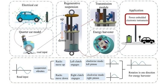
2.1. Details of the Transmission Mechanism

The transmission in the automobile’s suspension system is an essential element to ensure that the motion transmission to the energy harvester is highly efficient.
As opposed to the conventional rotational regenerative shock absorber, which frequently alters its direction of rotation responding to the linear movement when fluctuating up and down, a mechanical motion rectifier (MMR) turns the linear movement caused by road irregularities into a unidirectional rotational motion. This causes the piezoelectric harvester to spin continuously in one direction. An up mode and a down mode are the two modes of the MMR main function, as depicted in Figure 1. This occurs with the help of the two key elements, which are two parts of a one-way roller clutch to keep the rotation of the shaft and the piezoelectric scavenger always in the one direction to assure better performance in the energy-conversion process.
Figure 2 demonstrates the details of the transmission elements embedded in the regenerative suspension system. The essential components are a pair of rack and pinion, a single shaft, a lower cylinder, a piezoelectric harvester, and two one-way roller clutches, which are embedded inside the two pinions. Racks are connected to the external cylinder. The behavior of the working mechanism of the suspension parts responding to the oscillation exerted due to road unevenness is shown in Figure 3. The values of the transmission parameter are given by Table 1.
Vehicle vibrations arise when the car crosses over rough roads; the suspension system’s function is to absorb and mitigate these vibrations to ensure a comfortable ride. The outer cylinder of the suspension system responds to these vibrations by moving up and down. When the upper cylinder is compressed by the vehicle’s body and moves down, the two racks will also move downward along with the outer cylinder because they are fixed to it. In contrast, the two pinions are located above the inner cylinder without fixing them and always spin in the reverse way, relative to each other. Accordingly, as soon as the rack shifts up and down, a linear movement is carried to the left pinion, which revolves it clockwise and counterclockwise, respectively. Because of the influence of the two one-way roller clutches, which are the connecting point between the pinions and the shaft and are specifically embedded in the inner part of the pinions, at any moment, the two pinions and clutches will never be engaged to the shaft simultaneously, because one of them will be disengaged. The one-way roller clutch only transmits the torque to the pinion in one particular direction and bypassing it in the other. Therefore, with the exception of the pinions, all of the rotary components, including the shafts, bevel gears, and the piezo–magneto harvester in the regenerative suspension, always rotate in one direction. The primary function of the two bevel gears is that they convert the rotary motion of the short shaft by 90 with the purpose of rotating the piezo–magneto harvester.

2.2. The Piezoelectric Harvester Module

This study investigates the prospect of using piezoelectric transducers to replace the traditional generator commonly used in regenerative shock absorbers for potential energy harvesting. To fulfill this aim, this study uses a shock absorber that is supplemented with a novel magnetically coupled piezoelectric vibration energy harvester (MPVEH) for power generation. The harvester is designed with two noncontact rings to assure no power loss due to friction. It is also built to suit applications that have a rotational mechanism, which in our case is to convert the vibration energy within a vehicle suspension into electricity. With respect to energy conversion technologies, the power density harvested from the piezoelectric transducer is about three times higher than that of the electromagnetic generator. Hence, the proposed scavenger addresses an existing limitation associated with the electromagnetic transducers, such as low power density. The energy scavenger elements are made up of a pair of concentric rings. Four rectangular permanent magnetic plates are symmetrically attached to the inner surface of the stator ring, which is fixed to the lower cap of the cylinder. Between the outer ring and the magnetic plates are piezoelectric patches, and piezoelectric benders are embedded between the stator ring and the magnetic plates. A 3D-printed round plate is placed between the magnetic and the piezoelectric bender as a coupler. There are also magnetic plates attached symmetrically on the external surface of the rotator ring, which is fixed to the long shaft, to create periodic compression due to the repelling magnetic force acting on the piezoelectric benders, which will produce charges that can be extracted. Figure 4 shows a schematic of a magnetically coupled piezoelectric vibration energy harvester (MPVEH) composed of a fixed stator ring and a rotator ring. The outer and inner rings are both equipped with symmetrically placed magnets. The permanent magnetic materials all have identical dimensions, have a rectangular shape, and are symmetrically placed along the circumferential direction. The piezoelectric benders are embedded between the magnet and the outer ring’s inner surface. The piezoelectric benders and the magnets are coupled by round-shaped 3D-printed plates. Additionally, both the inner and outer rings are 3D-printed. As the inner surface of the stator ring is designed with disk support, the piezoelectric material can only be attached by its disk end. Upon transferring the linear motion to rotational motion due to the road vibration, the harvester creates periodic magnetic repelling forces, which then presses the piezoelectric benders. Since the piezoelectric pieces are fixed across the ends of their disks to the disk supports, and due to the presence of the connecting element between the magnet and the piezoelectric, the deformation caused by the magnetic forces are centered in the middle, allowing the piezoelectric disk to flex; hence, a higher voltage can be extracted.

3. Parametric Study

The key parameters that have a significant effect on the performance of MPVEH are examined in this section. Table 2 provides a listing of all the parameters, unless otherwise noted. The arrangement of the magnets has a significant influence on the performance of the regenerative suspension system, the magnetic coupling, and the power generated. The resistance torque caused by the magnets leads to poor mechanical transmission in the suspension. Although increasing the space between the two magnets reduces the resistance torque, a more effective way to reduce it is to have a particular arrangement of the magnets in which the magnets are arranged symmetrically and oppositely to enhance the performance of the suspension and the harvester [44].
Figure 5 shows the mechanism of the rotational magnetic force arrangement as well as the magnetic force decomposition. In the symmetrical, rotating magnet pairs ( m 1 and m 3 , m 2 and m 4 ), opposite magnetic forces are always present during rotation, i.e., one pair is attracted, while the other pair is repelled. This reduces the magnetic resistance torques that disturb and obstacle the rotation. Additionally, while the magnets fixed to the rotating ring rotate to the minimal distance from the magnets fixed to the static ring ( M 1 and M 3 , M 2 and M 4 ), their magnetic poles oppose each other or are identical. Thus, the directions of the repelling or attracting magnetic forces are similar to the deformation directions of the piezoelectric transducers. According to the magnetic arrangement in this work, the static magnets and rotating magnets can be represented as face-to-face poles. The magnetic poles of the magnets fixed to the stator ring are S, N, N, and S from M 1 to M 4 , respectively, while the magnetic poles of the magnets attached to the rotator ring are S, N, S, and N from m 1 to m 4 , respectively. A positive output voltage is created when piezoelectric deformation occurs due to magnetic repulsion forces. In contrast, a negative output voltage is created when magnetic attraction forces are present, as depicted in Figure 5d.
The gap d between the static and rotating magnets has a significant influence on the resistance torque as well as the energy harvesting. Magnetic tuning can be accomplished by adjusting the separation distance between two magnets to adjust the attraction and repulsion forces between them [45]. Modeling this effect requires describing the magnetic force as a function of the magnet properties and the separation distance. Describing this relationship using a simple analytical formula is not possible because of this complex and multidimensional relationship. An online interpolator is available through K&J Magnetics, Inc., based on an extensive dataset of experimental measurements [46]. An empirical equation is then derived from these data, describing the attraction or repulsion force between a pair of corresponding rectangular permanent magnets. The repulsion or attraction force F M can be expressed as
F M = l w t m n B r | B ( d ) | f ( d )
where the permanent magnet’s length, width, and thickness (in the direction of magnetization) are given by l m , w m , and t m , respectively, and its residual flux density is denoted by Br. n is an empirical corrective exponent which can be given as 1 / 3 . f ( d ) is a function that expresses the decadence of the magnetic repulsion or attraction force between two plates. | B d | is the magnitude of the flux density for every magnetic plate. | B ( d ) | , for a rectangular permanent magnetic plate, can be computed by the following formula [46]:
B d = B r π [ tan 1 l w 2 d 4 d 2 + l 2 + w 2 tan 1 l w 2 t m + d 4 t m + d 2 + l 2 + w 2 ]
f ( d ) = 1.749 + 1.145 e d / d 0 × 10 6 NT 2 · m ( 7 / 3 )
where d 0 = 1 mm.
An instant of the rotary motion of the energy harvester at the relative angle shown is illustrated in Figure 5b. This presents the decomposition of the magnetic repulsion force. There are two types of decomposition of the repulsion magnetic force— F M y and F M x —which act along or opposite the piezoelectric material’s polling direction, respectively. When the rotatory permanent rectangular magnet plates exist at point A, the acting magnetic force on the piezoelectric is F = 0 . Whereas the force at point B, which exists at any point between C and A, is F = F M y = F M sin α . At point C, the repulsion magnet force is F = F M .
The magnetic force can be calculated with a magnet of parameters given in Table 2. The magnetic force increases significantly at smaller distances between the two magnets, as shown in Figure 6.

4. Experimental Setup

To assess the effectiveness of the proposed design, the harvester was fabricated and an experiment was set up. Figure 7 presents the experimental setup for the bench test of the regenerative suspension system. An 858 table top MTS System was used for the bench tests, as shown in Figure 7a. The prototype of the regenerative suspension system is fabricated for the test, as depicted in Figure 7b. Figure 7c shows the components of the piezoelectric harvester. The parameters of the harvester are listed in Table 2. The harvester is connected to a full-bridge rectifier, and all four piezoelectric benders of the presented vibration energy harvester were connected either in parallel or in series to assess the generated output current and output voltage. Additionally, a variable resistor was used to provide a load and the output voltage across this load was measured using a digital oscilloscope (TDS2001c, Tektronix, Beaverton, OH, USA), as shown in Figure 7d,e. The outer diameter of the rotating ring is 75 mm, and the initial spacing between the magnet fixed to the rotating ring and the magnet attached to the static ring is 3 m m , unless noted otherwise. The piezoelectric bender disks used in this study (PZT-lead zirconate titanate) are commercially available. The rectangular permanent magnetic plates used are strong Neodymium Magnets (grade N42), supplied by K&J Magnetics, Inc.

5. Results and Discussion

Figure 8a illustrates the output of the open-circuit voltages of all piezoelectric bender disks under the vibration of 9 m m amplitude at 2.5 Hz . The spacing between the rotating magnet and the static magnet is 3 m m . We note that the voltage output of M1 and M2 has the opposite performance of the voltage output of M3 and M4, as a result of the difference in the type of force acting, dependent on whether the magnets were in a state of attraction or repulsion. We observe that there are some slight variations with respect to the output amplitude of the voltage among the four piezoelectric bender disks. We hypothesize that the reason behind this is that the spacing between the two magnets is not precisely 3 m m on each side due to some machining imperfections. In addition, the thickness variation of the adhesive used to attach the piezoelectric disk and the magnet could be another factor that changes the separation distance between the two magnets. Since the piezoelectric benders produce the same or opposite voltage output, this allows the PZT disks to be utilized directly in series or in parallel, thus minimizing circuit processing, as shown in Figure 8b,c. Because a piezoelectric transducer switches polarity based on the effect of magnetic force, the wires of M3 and M4 are always connected reversely. This means that the black wires of M3 and M4 should be connected to the red wires of M1 and M2 in the parallel circuit scenario, as depicted in Figure 8b.
The performance of the MPVEH is examined by measuring the open-circuit voltage and short-circuit current when the suspension system is subjected to cyclic compressive and tensile stresses exerted by the MTS testing machine.
Figure 9a–d demonstrate the influence of the external load resistance on the output peak and the root mean square (RMS) of current, voltage, and power. In Figure 9a,c, the output characteristic is shown in relation to the external load resistance. By incrementally increasing the load resistance from 4.7 k Ω to 11.2 M Ω , the output RMS and peak voltage show an increasing trend up to 62.2 V and 172 V , respectively, while the output RMS and peak current show a decreasing trend up to 5.56 μ A and 0.0154 m A , respectively. The harvested peak power was experimentally determined as P peak = V 2 peak / R ; the RMS of voltage was calculated as V r m s = 1 T 0 T V ( t ) 2 d t , with V being the load voltage across the resistance R; the RMS of current was computed as I r m s = V r m s / R ; and the average power can be roughly calculated as P avg = V rms 2 / R . The generated power changes with the load resistance and reaches the highest at the matching impedance. When the load resistance increases, both generated average power and peak power increase initially, and thereafter fall. As plotted in Figure 9b,d, as the generated average power and peak power amounted to the highest values of 0.948 m W and 14.86 m W , the matching resistances are 1.6 M Ω and 800 k Ω , respectively. The power is attained at 2.5 Hz and 9 m m vibration amplitude. The spacing between the two magnets was set to be 3 m m .
As illustrated in Figure 10, the gap distance between the magnet attached to the static ring and the magnet attached to the rotating ring significantly influences the open-circuit voltage. The test was conducted at 2.5 Hz and 9 m m vibration amplitude. It is clearly seen that when the spacing between the two PMs decreases, the RMS of voltage increases significantly. The lowest value of the generated RMS voltage is 35.70 V , recorded at the largest gap tested between the magnetic plates of 6 m m . In contrast, the peak value of the output voltage of 68.75 V occurs when the gap distance between magnetic plates is as minimum as 3 m m . However, it should be noted that the smaller the distance between the magnets, the greater the force of attraction and repulsion demonstrated in Figure 6, which can cause the piezoelectric material to collapse. The fracture of the thin ceramic layer of the piezoelectric bender is to be expected the most cause of harvester damage. Furthermore, the piezoelectric disk benders and the magnetic plates are bonded by adhesive (CECCORP C-POXY 5) in this study. Failure of the adhesive is another potential cause of device damage. Collapses were observed only at very narrow distances between the two permanent magnets of the stator and rotating rings that are less than 3 m m .
Figure 11a demonstrates the spectra of the open-circuit voltage of the magneto–piezoelectric vibration energy harvester under various road frequencies from the experiment. The results are obtained from a single piezoelectric disk of the piezoelectric harvester. In proportion to the excitation frequencies subjected to the regenerative suspension, as they increase, the harvester rotation speed and magnetic excitation frequencies increase; however, the amplitude of the open-circuit voltage of the piezoelectric harvester, which is approximately 28 V, remains almost unchanged at different excitation frequencies of 1 Hz, 2Hz, 3 Hz, 4 Hz, and 5 Hz. This indicates that the piezoelectric disks are subjected to constant maximum magnetic forces from their excitation magnets which can be determined by the design parameters by adjusting the separation distance between the two magnets, as shown in Figure 6. According to the equation of open-circuit voltage V o c = d F / c p , where d is the piezoelectric coefficient, F is the excitation force, and c p is the electric capacity of the piezoelectric material, the open-circuit voltage of the piezoelectric harvester is proportional to the excitation force. Thus, the MPVEH can provide relatively stable voltages across wide ranges of frequencies. The rotator ring is equipped with four excitation magnets, which stimulate each of the magnetically coupled piezoelectric disks four times in a single cycle of the rotator ring. Likewise, the load voltage with 1 M Ω load resistance was examined over a range of frequencies, as exhibited in Figure 11b. The basis for choosing a 1 M Ω resistance value is that it is close to the optimal resistance. As the data reveal, the load voltage rises slightly as the excitation frequency increases. The RMS values of the load voltages are 12.90 V , 13.07 V , 13.51 V , 13.57 V , and 13.58 V , at the excitation frequencies of 1 Hz , 2 Hz , 3 Hz , 4 Hz , and 5 Hz , respectively. The charge leakage phenomenon is observed under load conditions [44]. Charge leakage is relatively slow at higher excitation frequencies; therefore, the load voltage increases.
Figure 12a demonstrates the open-circuit output voltage of the vibration energy scavenger with the series-connected piezoelectric bender disks at different vibration amplitudes as a function of external load resistance. The separating distance between the two permanent magnets is set to 5 m m . Higher vibration amplitude and a greater resistive load tend to increase the output voltage. According to the plot, the highest generated voltage was specified to be around 7 M Ω at each vibration amplitude, which is considered to be the highest external electrical load used in the study. Figure 12b shows the closed-circuit output current. In contrast to the tendency of the output voltage, the output current has a propensity to diminish with increasing the external load resistance and to rise as vibration amplitude rises. Figure 12c shows the variation of the generated power acquired from all piezoelectric bender disks embedded in the fabricated suspension at different vibration amplitudes as a function of the external load resistance. A 3 m m vibration amplitude did not produce a very high average output power, nor did it demonstrate a remarkable peak. However, when the vibration amplitude was increased to 6 m m , the average output power increased dramatically, and the peak power became relatively notable at a particular optimum resistance. Whereas an outstanding peak was observed, as well as an increase in the output power at a 9 m m vibration amplitude. Both the 6 m m and 9 m m vibration amplitude share the same optimal resistive load of 1.6 M Ω , at which the peak output power was 0.177 m W and 0.315 m W , respectively.
As piezoelectric scavengers cannot be employed as standalone devices in most external sensors and in similar applications, it is necessary to rectify and store their outputs in order to be useful. A rectifying circuit is joined between the piezoelectric vibration energy harvester and the energy storage so that the generated voltage signals can be converted from AC to DC. Figure 13a shows the full-wave bridge rectifier that is used to maximize the energy conversion efficiency. Figure 13b,c show capacitor charging responses of the piezoelectric energy harvester of different capacitors under a vibration of 6 m m amplitude at 2.5 Hz , connected in series and in parallel, respectively. It is observed that both in series and in parallel connections, 10 μ F capacitors charge more rapidly than 100 μ F capacitors. At the parallel connection, the piezoelectric harvester can charge a capacitor that has a rated voltage of 50 V and a charging full capacity of 100 μ F from 1 V to 20 V fast in 31 s , which is hopeful to supply power for vehicle embedded electronic devices. In conjunction with appropriate capacitors, this can supply real-time power to small electronic devices. Through the capacitor, the device can be supplied with power directly, as well as storing surplus power.
Regarding robustness, there are many factors that makes the presented harvester reliable. For example, the exciting force acting on the piezoelectric material can be controlled by the gap distance between the two magnets. Regardless of the varying excitation frequencies, the exciting magnetic forces subjected on the piezoelectric material are relatively constant. Furthermore, after extensive testing, the prototype shows no obvious signs of damage, as demonstrated in Figure 14. Figure 14a shows signal of the external excitation input. Figure 14b,c show the produced open-circuit voltage versus time before and after subjecting to an external excitation over 10,000 cycles, respectively. It can be observed that the prototype did not show any damage after running continuously at a 5 mm amplitude at a 2.5 Hz frequency for over 10,000 cycles.

6. Conclusions

We presented a new vibration energy scavenger utilizing a magnetically coupled piezoelectric disks. The piezoelectric harvester comprises a stator ring and a rotator ring. On the surface of the static ring and on the inside of the rotator ring, permanent magnetic plates are installed. The piezoelectric disks are mounted between the magnetic plates and the stator ring’s inner surface. The harvester is driven by the unidirectional shock absorber. The shock absorber transmission parts were modified to magnify the gear ratio to 1:2. It was achieved using a large and a small bevel gear. The aim of this work is to power embedded electrical devices of automobiles. A prototype of the presented energy-recovery damper was constructed, and experiments were performed utilizing a MTS testing system. Several parameters of the vibration amplitude, resistive load, and the separating distance between the magnetically coupled permanent magnets and excitation frequencies were deemed to enhance the presented regenerative shock absorber. Thus, the optimal separating distance was found to be 3 m m for the highest power generation. This implies that the smaller the gap between magnets, the higher the power output. In MPVEH, each piezoelectric transducer generates an exact opposite or equal voltage for the duration of the rotating period. Thus, they can be connected directly in series or in parallel. The prototype exhibited no damage after operating constantly for 10,000 cycles at a vibration amplitude of 5 m m at a frequency of 2.5 Hz . The energy-recovery damper can produce a peak power of 14.86 m W and an average power of 0.95 m W at a 9 m m vibration amplitude and 2.5 Hz exciting frequency with a gap distance of 3 m m . Additionally, the proposed energy-recovery damper can produce high and relatively constant open-circuit voltages regardless of the excitation frequency. This indicates that the regenerative suspension system is robust and has a wide frequency range.

Author Contributions

Conceptualization, S.A.; methodology, S.A.; formal analysis, S.A.; investigation, S.A.; resources, R.G.; data curation, S.A.; writing—original draft preparation, S.A.; writing—review and editing, R.G. and D.H.; supervision, R.G. and D.H. All authors have read and agreed to the published version of the manuscript.

Funding

This research was partially funded by Florida High Tech Corridor grant number FHT 21-10.

Institutional Review Board Statement

Not applicable.

Informed Consent Statement

Not applicable.

Data Availability Statement

Not applicable.

Acknowledgments

The authors gratefully acknowledge John Cotter for the assistance with fabrication.

Conflicts of Interest

The authors declare no conflict of interest.

Abbreviations

The following abbreviations are used in this manuscript:
RMSroot mean square
MPVEHmagnetically coupled piezoelectric vibration energy harvester
PZTlead zirconate titanate

References

  1. Campbell, S.; O’Mahony, N.; Krpalcova, L.; Riordan, D.; Walsh, J.; Murphy, A.; Ryan, C. Sensor technology in autonomous vehicles: A review. In Proceedings of the 2018 29th Irish Signals and Systems Conference (ISSC), Belfast, UK, 21–22 June 2018; pp. 1–4. [Google Scholar]
  2. Ignatious, H.A.; Hesham-El-Sayed; Khan, M. An overview of sensors in Autonomous Vehicles. Procedia Comput. Sci. 2022, 198, 736–741. [Google Scholar] [CrossRef]
  3. Morangueira, Y.L.; Pereira, J.C.d.C. Energy harvesting assessment with a coupled full car and piezoelectric model. Energy 2020, 210, 118668. [Google Scholar] [CrossRef]
  4. Hartley, J.; McLellan, R.; Richmond, J.; Day, A.; Campean, I. Regenerative braking system evaluation on a full electric vehicle. In Innovations in Fuel Economy and Sustainable Road Transport; Elsevier: Amsterdam, The Netherlands, 2011; pp. 73–86. [Google Scholar]
  5. Lv, C.; Zhang, J.; Li, Y.; Yuan, Y. Mechanism analysis and evaluation methodology of regenerative braking contribution to energy efficiency improvement of electrified vehicles. Energy Convers. Manag. 2015, 92, 469–482. [Google Scholar] [CrossRef]
  6. Qiu, C.; Wang, G. New evaluation methodology of regenerative braking contribution to energy efficiency improvement of electric vehicles. Energy Convers. Manag. 2016, 119, 389–398. [Google Scholar] [CrossRef]
  7. Neelakantan, V.A. Modeling, Design, Testing and Control of a Two-Stage Actuation Mechanism Using Piezoelectric Actuators for Automotive Applications; The Ohio State University: Columbus, OH, USA, 2005. [Google Scholar]
  8. Wang, Z.; Zhang, T.; Zhang, Z.; Yuan, Y.; Liu, Y. A high-efficiency regenerative shock absorber considering twin ball screws transmissions for application in range-extended electric vehicles. Energy Built Environ. 2020, 1, 36–49. [Google Scholar] [CrossRef]
  9. Zhang, J.-Q.; Peng, Z.-Z.; Zhang, L.; Zhang, Y. A review on energy-regenerative suspension systems for vehicles. In Proceedings of the World Congress on Engineering, London, UK, 3–5 July 2013; Volume 3, pp. 3–5. [Google Scholar]
  10. Van Schaijk, R.; Elfrink, R.; Oudenhoven, J.; Pop, V.; Wang, Z.; Renaud, M. A MEMS vibration energy harvester for automotive applications. In Proceedings of the International Society for Optics and Photonics, Smart Sensors, Actuators, and MEMS VI, Grenoble, France, 24–26 April 2013; Volume 8763, p. 876305. [Google Scholar]
  11. Cheah, L.; Evans, C.; Bandivadekar, A.; Heywood, J. Factor of two: Halving the fuel consumption of new US automobiles by 2035. In Reducing Climate Impacts in the Transportation Sector; Springer: Berlin, Germany, 2008; pp. 49–71. [Google Scholar]
  12. Ali, M.K.A.; Hou, X.; Mai, L.; Chen, B.; Turkson, R.F.; Cai, Q. Reducing frictional power losses and improving the scuffing resistance in automotive engines using hybrid nanomaterials as nano-lubricant additives. Wear 2016, 364, 270–281. [Google Scholar] [CrossRef]
  13. Zhang, X.; Mi, C. Vehicle Power Management: Modeling, Control and Optimization; Springer Science & Business Media: Heidelberg/Berlin, Germany; New York, NY, USA, 2011. [Google Scholar]
  14. Ali, M.K.A.; Hou, X.; Elagouz, A.; Essa, F.; Abdelkareem, M.A. Minimizing of the boundary friction coefficient in automotive engines using Al2O3 and TiO2 nanoparticles. J. Nanopartic. Res. 2016, 18, 1–16. [Google Scholar] [CrossRef]
  15. Abdelkareem, M.A.; Xu, L.; Ali, M.K.A.; Elagouz, A.; Mi, J.; Guo, S.; Liu, Y.; Zuo, L. Vibration energy harvesting in automotive suspension system: A detailed review. Appl. Energy 2018, 229, 672–699. [Google Scholar] [CrossRef]
  16. Chu, S.; Majumdar, A. Opportunities and challenges for a sustainable energy future. Nature 2012, 488, 294–303. [Google Scholar] [CrossRef]
  17. Holmberg, K.; Andersson, P.; Erdemir, A. Global energy consumption due to friction in passenger cars. Tribol. Int. 2012, 47, 221–234. [Google Scholar] [CrossRef]
  18. Tie, S.F.; Tan, C.W. A review of energy sources and energy management system in electric vehicles. Renew. Sustain. Energy Rev. 2013, 20, 82–102. [Google Scholar] [CrossRef]
  19. Fontaras, G.; Zacharof, N.G.; Ciuffo, B. Fuel consumption and CO2 emissions from passenger cars in Europe–Laboratory versus real-world emissions. Prog. Energy Combust. Sci. 2017, 60, 97–131. [Google Scholar] [CrossRef]
  20. Khoshnoud, F.; Zhang, Y.; Shimura, R.; Shahba, A.; Jin, G.; Pissanidis, G.; Chen, Y.K.; De Silva, C.W. Energy regeneration from suspension dynamic modes and self-powered actuation. IEEE/ASME Trans. Mechatron. 2015, 20, 2513–2524. [Google Scholar] [CrossRef] [Green Version]
  21. Suda, Y.; Shiiba, T. A new hybrid suspension system with active control and energy regeneration. Veh. Syst. Dyn. 1996, 25, 641–654. [Google Scholar] [CrossRef]
  22. Naruse, Y.; Matsubara, N.; Mabuchi, K.; Izumi, M.; Suzuki, S. Electrostatic micro power generation from low-frequency vibration such as human motion. J. Micromech. Microeng. 2009, 19, 094002. [Google Scholar] [CrossRef]
  23. Deterre, M.; Risquez, S.; Bouthaud, B.; Dal Molin, R.; Woytasik, M.; Lefeuvre, E. Multilayer out-of-plane overlap electrostatic energy harvesting structure actuated by blood pressure for powering intra-cardiac implants. J. Phys. Conf. Ser. 2013, 476, 012039. [Google Scholar] [CrossRef] [Green Version]
  24. Zuo, L.; Zhang, P.S. Energy harvesting, ride comfort, and road handling of regenerative vehicle suspensions. J. Vib. Acoust. 2013, 135, 011002. [Google Scholar] [CrossRef]
  25. Kim, Y.; Hwang, W.; Kee, C.; Yi, H. Active vibration control of a suspension system using an electromagnetic damper. Proc. Inst. Mech. Eng. Part J. Automob. Eng. 2001, 215, 865–873. [Google Scholar] [CrossRef]
  26. El-Sayed, A.R.; Tai, K.; Biglarbegian, M.; Mahmud, S. A survey on recent energy harvesting mechanisms. In Proceedings of the 2016 IEEE Canadian conference on electrical and computer engineering (CCECE), Vancouver, BC, Canada, 15–18 May 2016; pp. 1–5. [Google Scholar]
  27. Karnopp, D. Permanent magnet linear motors used as variable mechanical dampers for vehicle suspensions. Veh. Syst. Dyn. 1989, 18, 187–200. [Google Scholar] [CrossRef]
  28. Nakano, K.; Suda, Y.; Nakadai, S. Self-powered active vibration control using a single electric actuator. J. Sound Vib. 2003, 260, 213–235. [Google Scholar] [CrossRef]
  29. Li, Z.; Zuo, L.; Luhrs, G.; Lin, L.; Qin, Y.x. Electromagnetic energy-harvesting shock absorbers: Design, modeling, and road tests. IEEE Trans. Veh. Technol. 2012, 62, 1065–1074. [Google Scholar] [CrossRef]
  30. Nakano, K. Combined type self-powered active vibration control of truck cabins. Veh. Syst. Dyn. 2004, 41, 449–473. [Google Scholar] [CrossRef]
  31. Salman, W.; Qi, L.; Zhu, X.; Pan, H.; Zhang, X.; Bano, S.; Zhang, Z.; Yuan, Y. A high-efficiency energy regenerative shock absorber using helical gears for powering low-wattage electrical device of electric vehicles. Energy 2018, 159, 361–372. [Google Scholar] [CrossRef]
  32. Li, Z.; Zuo, L.; Kuang, J.; Luhrs, G. Energy-harvesting shock absorber with a mechanical motion rectifier. Smart Mater. Struct. 2012, 22, 025008. [Google Scholar] [CrossRef]
  33. Li, H.; Zheng, P.; Zhang, T.; Zou, Y.; Pan, Y.; Zhang, Z.; Azam, A. A high-efficiency energy regenerative shock absorber for powering auxiliary devices of new energy driverless buses. Appl. Energy 2021, 295, 117020. [Google Scholar] [CrossRef]
  34. Liu, Y.; Xu, L.; Zuo, L. Design, modeling, lab, and field tests of a mechanical-motion-rectifier-based energy harvester using a ball-screw mechanism. IEEE/ASME Trans. Mechatron. 2017, 22, 1933–1943. [Google Scholar] [CrossRef]
  35. Liu, Y.G.; Zhang, Z.T.; Chen, W.W.; Ke, X.T.; Zhang, X.T.; Pan, H.Y.; Liu, X.L. A Regenerative Vehicle Shock Absorber. Chinese Patent CN105114503, 6 September 2015. [Google Scholar]
  36. Zhang, Z.; Zhang, X.; Chen, W.; Rasim, Y.; Salman, W.; Pan, H.; Yuan, Y.; Wang, C. A high-efficiency energy regenerative shock absorber using supercapacitors for renewable energy applications in range extended electric vehicle. Appl. Energy 2016, 178, 177–188. [Google Scholar] [CrossRef]
  37. Roundy, S.; Wright, P.K. A piezoelectric vibration based generator for wireless electronics. Smart Mater. Struct. 2004, 13, 1131. [Google Scholar] [CrossRef] [Green Version]
  38. Zhao, Z.; Wang, T.; Shi, J.; Zhang, B.; Zhang, R.; Li, M.; Wen, Y. Analysis and application of the piezoelectric energy harvester on light electric logistics vehicle suspension systems. Energy Sci. Eng. 2019, 7, 2741–2755. [Google Scholar] [CrossRef] [Green Version]
  39. Darabseh, T.; Al-Yafeai, D.; Mourad, A.H.I.; Almaskari, F. Piezoelectric method-based harvested energy evaluation from car suspension system: Simulation and experimental study. Energy Sci. Eng. 2021, 9, 417–433. [Google Scholar] [CrossRef]
  40. Lee, H.; Jang, H.; Park, J.; Jeong, S.; Park, T.; Choi, S. Design of a piezoelectric energy-harvesting shock absorber system for a vehicle. Integr. Ferroelectr. 2013, 141, 32–44. [Google Scholar] [CrossRef]
  41. Xie, X.; Wang, Q. Energy harvesting from a vehicle suspension system. Energy 2015, 86, 385–392. [Google Scholar] [CrossRef]
  42. Alhumaid, S.; Hess, D.; Guldiken, R. Energy regeneration from vehicle unidirectional suspension system by a non-contact piezo-magneto harvester. Eng. Res. Express 2021, 3, 015033. [Google Scholar] [CrossRef]
  43. Zhao, Z.; Wang, T.; Zhang, B.; Shi, J. Energy Harvesting from Vehicle Suspension System by Piezoelectric Harvester. Math. Probl. Eng. 2019, 2019, 1086983. [Google Scholar] [CrossRef] [Green Version]
  44. Zhao, L.C.; Zou, H.X.; Yan, G.; Liu, F.R.; Tan, T.; Wei, K.X.; Zhang, W.M. Magnetic coupling and flextensional amplification mechanisms for high-robustness ambient wind energy harvesting. Energy Convers. Manag. 2019, 201, 112166. [Google Scholar] [CrossRef]
  45. Al-Ashtari, W.; Hunstig, M.; Hemsel, T.; Sextro, W. Frequency tuning of piezoelectric energy harvesters by magnetic force. Smart Mater. Struct. 2012, 21, 035019. [Google Scholar] [CrossRef]
  46. k&J Magnetics. The Original K&J Magnet Calculator. 2011. Available online: https://www.kjmagnetics.com/calculator.asp (accessed on 28 February 2022).
Figure 1. Flowchart of the introduced vehicle regenerative suspension.
Energies 15 04476 g001
Figure 2. Schematic representation of the suspension transmission elements.
Energies 15 04476 g002
Figure 3. Schematic illustration of the transmission mechanism.
Energies 15 04476 g003
Figure 4. Schematic of the magnetically coupled piezoelectric vibration energy harvester (MPVEH).
Energies 15 04476 g004
Figure 5. (a) The magnets that are arranged in a symmetrical opposite manner; (b) the magnetic force decomposition; (c) the magnetic force; and (d) the output voltage plot.
Energies 15 04476 g005
Figure 6. The magnetic force versus the separation distance between magnets.
Energies 15 04476 g006
Figure 7. Bench tests of the presented regenerative suspension system.
Energies 15 04476 g007
Figure 8. (a) Output voltages of all piezoelectric bender disks. (b) Schematic circuit diagram showing the parallel connection of the piezoelectric disks. (c) Schematic circuit diagram showing the series connection of the piezoelectric disks.
Energies 15 04476 g008
Figure 9. (a) RMS of voltage, current, and (b) electric power of the piezoelectric vibration energy harvester for piezoelectric benders connected in series at variations of external load resistance. (c) Open-circuit voltage, short-circuit current, and (d) generated power as a function of the external load resistance for piezoelectric benders connected in series.
Energies 15 04476 g009
Figure 10. Output voltage reliance on the spacing between the two permanent magnets of the stator and the rotator.
Energies 15 04476 g010
Figure 11. MPVEH response to different excitation frequencies. (a) Open-circuit voltage spectra and (b) output voltage spectra with resistance of 1 M Ω .
Energies 15 04476 g011
Figure 12. (a) RMS of voltage, (b) current, and (c) electric power of the piezoelectric vibration energy harvester for piezoelectric benders connected in series at different amplitudes of oscillation as a function of external load resistance.
Energies 15 04476 g012
Figure 13. (a) An electrical circuit diagram for charging a capacitor. (b) The capacitor charging response of the MPVEH at a series connection. (c) The capacitor charging response of the MPVEH at a parallel connection.
Energies 15 04476 g013
Figure 14. (a) External excitation input; (b) voltage versus time before 10,000 cycles; and (c) voltage versus time after 10,000 cycles.
Energies 15 04476 g014
Table 1. The transmission parameter values.
ParameterValue
The rack module1.5
The pinion module1.5
The pinion gear pitch diameter45 mm
The speed ratio of the bevel gears 1 : 2
Table 2. The prototype’s dimensions and materials.
ParameterValue
Piezoelectric disk bender
Brass Diameter35 mm
Ceramic Diameter25 mm
Overall Thickness0.55 mm
Brass Thickness0.3 mm
Magnet
The residuals flux density B r 1.3 T
Magnet’s thickness t m 3.175 mm
Magnet’s width w m 9.525 mm
Magnet’s length l m 25.4 mm
Magnet’s volume v m 768.14 mm
Publisher’s Note: MDPI stays neutral with regard to jurisdictional claims in published maps and institutional affiliations.

