Article

Numerical Investigation of the Pre-Chamber and Nozzle Design in the Gasoline Engine of an Agricultural Tractor

College of Engineering, China Agricultural University, Beijing 100083, China
*
Author to whom correspondence should be addressed.
Submission received: 4 April 2022 / Revised: 9 June 2022 / Accepted: 10 June 2022 / Published: 20 June 2022
(This article belongs to the Special Issue Experiments and Simulations of Combustion Process)

Abstract

:
With the rapid development of agriculture in China today, the demand for agricultural machinery is rapidly increasing. A large amount of exhaust gas emissions poses a severe threat to the environment. To better promote engine fuel and air mixing, enhance engine performance, and achieve low emissions, we conducted a numerical study of the pre-chamber and nozzle design in a gasoline engine for an agricultural tractor by using the G-equation method in Converge CFD software. The relevant optimization of the three model parameters in the G-equation was performed using the improved particle swarm algorithm (PSO). The model parameters after optimization by the PSO algorithm were: a 1 = 0.77 , b 1 = 2.0 , b 3 = 1.0 . It was confirmed that the predicted engine performance was enhanced greatly with the pre-chamber system. More importantly, the results reveal that the volume and area ratios of the pre-chamber played a crucial role in the performance of the pre-chamber. Through a series of parametric studies on the pre-chamber and main chamber characteristics, we can identify the best sets of volume and area ratios based on the combustion reaction progress, the turbulent mixing profiles, and the exhaust gas emission. The turbulent maximum strength and the exhaust gas concentration of nitrogen oxides can differ by 13 and 18 times, respectively. In practical design, we recommend the optimization of the concerned metrics with the findings in the paper.

1. Introduction

Our modern society is heavily dependent on agricultural machinery systems, not only for producing food but also for the supply of various goods and services, which have become an integral part of our lives. Although the agricultural machinery systems bring many benefits to society, they also pose several threats, such as energy resource depletion and environmental pollution problems, resulting in adverse effects on the global climate and human health. China is a significant agricultural country in the world, accounting for 7% of the world’s total cultivated land. The number of agricultural employees was 134.09 million in 2019 [1]. Consequently, considering the size of Chinese agriculture and its potential negative impacts on air pollution, it is of great necessity to estimate the pollutant emissions of agricultural machinery to provide basic information for future studies of the creation of effective emission mitigation measures.
To better promote engine fuel and air mixing, enhance engine performance, and achieve the result of emission reduction, in this study, we studied the combustion and emission characteristics of a gasoline engine assisted with a pre-chamber system. Pre-chamber combustion is a successful and promising combustion method for improving combustion speed and stability [2]. A pre-chamber with a small volume is connected to the main chamber by multiple small orifices in the pre-chamber system. The mixture inside the pre-chamber is ignited by a spark plug. The pressure in the pre-chamber then rapidly rises due to combustion and much surpasses the pressure in the main chamber, allowing a forceful jet to enter the main chamber through the aperture and ignite the combustible mixture in dispersed spots by thermal, turbulence, and chemical causes [3]. There are often two types of such pre-chambers considering the approach of realization. The one consists of a plug and the pre-chamber body. Due to the piston moving up, the air–fuel mixture formed in the main chamber can be pressed into the pre-chamber automatically in a compressing stroke [4,5]. The other one consists of a spark plug, an injector, and a pre-chamber body. The injector and the sparkplug are mounted directly on the pre-chamber, and the pre-chamber is connected to the main chamber. During operation, a little fuel is injected to form an air–fuel mixture inside the pre-chamber before sparking [6,7].
In combination with technologies such as the Miller cycle, exhaust gas recirculation, (EGR), and lean burn, the pre-chamber system can significantly reduce the energy loss during pumping, heat transfer, and combustion, and has been widely used in gasoline engines in recent years [8]. Ricardo Dolphin et al. [9] designed the first gasoline engine with a pre-chamber in 1918. Inspired by this concept, Toyota [10] developed a lean burn engine with a pre-chamber called the turbulence generating pot (TGP). It was found that the lean burn limit was extended and the flame propagation velocity was increased with the pre-chamber adopted in the engine. Tom G. Adams et al. [11] used a Ford 351-C engine to conduct an investigation on the naturally aspirated auxiliary combustion torch chamber to provide post-combustion turbulence. Walter Brandstetter et al. [12] optimized the pre-chamber combustion process in Volkswagen vehicles by using a 1300 cm3 four-cylinder water-cooled inline engine. In the 1970s, Gussak et al. [13,14] began researching the technique known as torch ignition and discovered that it lowered the ignition instability coefficient by one order of magnitude. Honda later developed a pre-chamber combustion system called Compound Vortex Controlled Combustion (CVCC) based on the same concept [15]. Due to the narrow ignition limit and the large quenching thickness of gasoline, pre-chamber technology has been mainly applied to diesel and natural gas engines. However, with the increasing demand for the thermal efficiency and power of gasoline engines, the research on pre-chamber technologies for passenger vehicles has gradually increased [16]. On this basis, the MAHLE company has performed continuous and comprehensive research on the structure, combustion, and emission characteristics of the pre-combustion chamber system to reduce the fuel consumption to 200 g (/kw∙h) on multi-cylinder engines [17,18,19,20,21]. The IAV company carried out a detailed study of the pre-chamber system, including the cooling system, low-pressure air–fuel injection system, knock measurement, etc. [22,23]. Ponnya Hlaing et al. [24] studied the effect of pre-chamber enrichment on the lean burn pre-chamber spark ignition combustion concept with a narrow-throat geometry. They found that pre-chamber spark ignition (PCSI) can significantly reduce NOx emissions while maintaining short combustion durations. Qin et al. [25] used direct numerical simulation (DNS) with detailed chemical kinetics to investigate the mixing and ignition mechanisms of the pre-chamber system. Their results showed that the intermediate species OH, CH2O, and HO2 are critical for flame stabilization and propagation in the main combustion chamber due to their high reactivity. The burning velocity in the main chamber could be sped up to 30 times with the pre-chamber system. Hua et al. [26] investigated the injection parameters, combustion characteristics, and optimized pollutant emissions in the pre-chamber. Three types of optimized pre-chambers were tested, and the results showed that with a smaller pre-chamber volume, better engine performance and lower pollutant emissions were achieved. Biswas et al. [27,28] used high-speed Schlieren and OH* chemiluminescence imaging to study the ignition mechanism of a pre-chamber fueled by premixed H2/air mixtures. Two ignition mechanisms of jet ignition and flame ignition were observed, and the angle jets produced a shorter combustion duration in the main chamber. Shah et al. [29,30,31] conducted various experimental studies on the performance and emission characteristics of pre-chamber systems in a natural gas (NG) engine. They found that the pre-chamber considerably improved the ignition ability, with an increase in the lambda limit of 0.8–1.0 units and in the EGR limit of 5–8%. Furthermore, a very-fuel-rich pre-chamber mixture may give greater ignition for the leaner main chamber combination. Toulson et al. [32] investigated the use of NG and propane in an optical single-cylinder engine using a turbulent jet ignition pre-chamber system. Due to the several scattered ignition sites indicated by the optical pictures, the turbulent jet ignition permitted shorter flame travel lengths, considerably reducing the combustion time and enabling lean burn with a lambda greater than two. F. Li et al. [33] studied the ignition mechanism and combustion characteristics of the pre-chamber jet ignition system in an optical rapid compression machine (RCM). A pre-chamber was designed referring to the results obtained in RCM and applied in a single-cylinder NG engine. The combustion and emission characteristics of the pre-chamber jet ignition (PJI) system were investigated. Xiong et al. [34] investigated the effect of the orifice diameter and number of pre-chambers on the combustion characteristics of the engine by combining simulations and experiments using an NG engine. It was found that with the same orifice diameter, a seven-orifice configuration presented a higher thermal efficiency compared to a four-orifice configuration due to heat loss reduction by decreasing the impingement of the jet flame on the cylinder wall. Giulio et al. [35] investigated annular combustors, and the results showed how small differences between the flame responses lead to one strong topological change in the dynamical system phase space, making the system prefer orientation angles at two azimuthal locations, one opposite of the other in the annulus, as found in the experiments. Sohail et al. [36,37] studied the spouted-bed gasification of flame-retardant textiles based on combustion chamber dynamics, and found that thermal value-added techniques (e.g., gasification) would help to avoid the formation of additional toxic hazards. Alternative solutions were provided as well.
The above literature review shows that the pre-chamber system can greatly improve the combustion efficiency and stability of gasoline engines. However, there is a lack of research involving the application of pre-chamber technology in agricultural machinery, despite the fact that the total power of a gasoline engine for agricultural machinery continued to increase from 3747.8 MW in 2017 to 4313.0 MW in 2019 [1]. In addition, the exhaust emissions of agricultural machinery also cause serious pollution of the environment. Therefore, it is necessary to use pre-chamber technology to reduce pollution emissions from agricultural machinery. In this study, we used Converge CFD software to study the combustion and emission characteristics of the pre-chamber system in an agricultural tractor. Through a series of parametric studies on the pre-chamber and main chamber’s characteristics, it was observed that the reaction progress, the turbulent mixing profiles, and the exhaust gas emissions responded to different parameters, providing guidelines for future designs and a better reduction in the emissions from agricultural tractors.

2. Numerical Simulation and Methods

2.1. Modeling Geometry

The basic design of the pre-chamber in this study was a small pre-chamber installed on top of the main combustion chamber. Within the pre-chamber, there was a fuel injection port and a spark plug that ignites the fuel mixture. The pre-chamber was connected to the main combustion chamber through eight connection ports. The main chamber contained a fuel-lean mixture, which is generally not conducive to flame propagation. More detailed geometry information of the pre-chamber model used in this paper can be extracted from Ashish’s paper [38]. The geometries of the piston and liner are shown in Figure 1. The geometry of the pre-chamber was the Wartsila model, as described in Ashish’s paper [38]. The specifications of the test engine are given in Table 1.

2.2. Turbulent Combustion Model (G-Equation and SAGE) Optimization

In the present study, two different turbulent combustion models were investigated: the G-equation and SAGE models. The SAGE detailed chemistry model uses an appropriate mechanism to verify that the mechanism is valid for simulated conditions, such as temperature, pressure, etc. More detailed or different mechanisms can be used in the SAGE detailed model, and reaction rates can be scaled. SAGE can be used for premixed, non-premixed, and partially premixed combustion conditions and multiple fuels. However, the SAGE model requires an accurate chemical mechanism, and running it is relatively computationally expensive if the mechanism is large. The G-equation model is a premixed combustion model that typically runs faster than the detailed chemistry model, and a reaction mechanism may not be required. The G-equation model accounts for turbulent mixing enhancement through the turbulent flame speed closure, but it does not account for the commutation error. The model tracks the flame front using a level set, and the G is the distance to the flame front. As the level set approaches, the G-equation has superior performance in capturing the flame front. In the turbulent environment, the filtered scalar G follows the following governing equation:
ρ G ˜ t + ρ u i ˜ G ˜ x i = ρ D t κ ˜ | G ˜ x i | + ρ u s t | G ˜ x i |
The turbulent flame speed is a modified value of the laminar flame speed, as follows:
s t = s l + u { a 4 b 3 2 2 b 1 D a + [ ( a 4 b 3 2 2 b 1 D a ) 2 + a 4 b 3 2 D a ] 1 / 2 }
where the dimensionless groups are:
D a = s l l t u l F
l F = ( λ / c p ) o ( ρ s l ) u
l t = c μ 3 / 4 k 3 / 2 ε
The empirical correlation is expressed in terms of the laminar flame speed ( s l ), turbulent velocity ( u ), turbulent flame thickness ( l F ), turbulent mixing scale ( l t ), and the Damkohler number (Da). The Da is defined as the ratio of the chemical time-scale to the turbulent mixing time-scale. Increasing   b 1 increases the burning rates, while decreasing b 1   decreases the burning rates. Here, Gulder’s correlation was used for the laminar flame speed, as follows:
s l _ r e f = ω ϕ η e x p [ ξ ( ϕ 1.075 ) 2 ]
One key point of this model in predicting turbulent combustion is parameterization, while other parameters are physical variables, and b 1 , b 3 , and a 4 are model parameters that are subject to specification. In this study, we aimed to find the optimal value combinations for the G-equation to work in the context of this problem.
The flame fronts captured by these two models are presented in Figure 2. The flame front predicted with the SAGE model is presented in purple, while the flame front computed with the G-equation is presented in green. It can be seen that both the SAGE and G-equation models captured the asymmetrical initiation flame front due to the non-centered position of the spark plug. However, at the same crank angle degree (CAD), the propagation of the flame front captured by the G-equation was faster in the leaner main chamber, but the completion of combustion in the richer pre-chamber was slower. Figure 3 and Figure 4 further demonstrate the difference in the flame propagation rate. The main combustion process was completed at a much higher rate in the G-equation than in the SAGE model.
To further explore the physics and find the optimal parameters used for this simulation, we searched for the parameter space in the G-equation, and the relevant optimization of the model parameters was performed using the improved particle swarm algorithm (PSO). Three parameters in the G-equation model were used as design variables, and the objective function mainly considered A and B. A is the integrated heat release, and B is the pressure. The objective function is shown in Equation (7), as follows:
M i n   f ( a 1 , b 1 , b 3 ) = A + B
If all the models in the particle swarm optimization process are performed by numerical simulation or actual experiments, this will make the computational effort increase dramatically, while the establishment of the Kriging agent model can effectively solve this problem. Kriging is a regression analysis method that consists of a regression part and a parameter part, as shown in Equation (8):
y ( x ) = μ + Z ( x )
where x is a spatial data point with n dimensions, the polynomial μ is the average value of the random process, and Z ( x ) is the random distribution. In order to obtain a more accurate Kriging agent model, in this study, 50 models with different parameters were first randomly generated, numerically simulated, and calculated in CONVERGE software, and then a Kriging agent model was established from these 50 sets of values. After accuracy verification, the model was used for subsequent particle swarm optimization. The PSO algorithm is a classical and effective population intelligence optimization algorithm with a strong global search capability that was proposed by Eberhart and Kennedy in 1995 [39]. Each particle in PSO has two characteristics—velocity and position—and the optimization process of PSO is achieved by multiple iterations of the velocity and position, whose iteration equation is as follows:
{ v i j + 1 = w v i + c 1 r 1 ( p b e s t i j p i j ) + c 2 r 2 ( g b e s t i j g i j ) p i j + 1 = p i j + v i j + 1
where w is the inertia factor, and its value is non-negative, representing the particle’s last velocity on the current degree of particle impact; according to experience, w is generally 0.9. c 1 and c 2 are the learning factors; usually, c 1 = c 2 = 2. r 1 and r 2 are the random values, and their values range between 0 and 1.
In the classical PSO algorithm, the inertia factor is a constant. The inertia factor plays different roles at different stages of optimization. For example, at the beginning of optimization, a larger inertia factor can enhance the global search capability, but at the end of optimization, a smaller inertia factor can enhance the local search capability. Therefore, a larger inertia factor at the beginning of optimization and a smaller inertia factor at the end of optimization can significantly improve the solving ability of PSO. It was also found that the rate of change in the inertia factor will greatly affect the global searching ability of PSO. Based on this, Feng et al. [40] proposed to continuously adjust the inertia factor with the help of the skip line function during the optimization process. The inertia factor has a larger value and changes slowly at the beginning of the iteration, and has a smaller value and changes quickly at the end of the iteration, which facilitates the PSO to switch from global optimization to local optimization gradually. The skip line function is shown in Equation (10):
y = 8 a 3 x 2 + 4 a 2  
Solving for the second-order derivative of Equation (10), Equation (11) is obtained:
y = 16 a 3 ( 4 a 2 3 x 2 ) ( 4 a 2 + x 2 ) 3
According to Equation (10), the coordinates of the inflection point of the skip line function are ( ± 2 3 3 a , 3 2 a ), and the function has the characteristic that its function value is larger and the rate of the curve change is minimal at the point (0, 2a), while the function value is smaller and the rate of the curve change is maximal at the inflection point. Based on this characteristic, the adjustment strategy for designing the inertia factor is as follows.
w ( i ) = w m i n + ( w m a x w m i n ) { 2 a [ 8 a 3 ( η i η m a x 2 3 3 a ) + 4 a 2 ] 3 } = w m i n + ( w m a x w m i n ) ( 12 h ( i ) 2 + 3 3 )
where w m i n and w m a x are the maximum and minimum values of the inertia factor, respectively. η i   and η m a x denote the current iteration number and the maximum iteration number, respectively. Figure 3 shows the basic flow of the PSO algorithm, and Figure 4 shows the iterative process.
The heat release and pressure parameters of different models were studied quantitatively. In comparison to the SAGE model, one key benchmark value is the total heat release, which is the integration of the heat release rate. The engine’s performance was sensitive to the total heat release as well as the pressure for different crank angles, as shown in Figure 5. The model parameters after optimization by the PSO algorithm were: a 1 = 0.77 , b 1 = 2.0 , b 3 = 1.0 . Figure 5 shows a comparison of the SAGE and optimized G-equation models before and after.
The results show that there was a significant difference between the G-equation results and the SAGE results. We believe that the G-equation can better capture the behavior of the flame front propagation in a turbulence context because the G-equation model considers the transportation of the tracer variable in the turbulence. Hence, in the following simulations, the G-equation with the SAGE solver outside the flame region, as well as the default parameters, were used for the presentation of the standard results.
The laminar flame speed results are given in Figure 6, which is a function dominated by the mixing ratio of the fuel and air. Therefore, it can be found that the flame speed peaked at a contour, which denotes the intermediate mixing ratio region created due to the mixing between the injected gas and the lean environment. Figure 6 also shows the velocity fluctuation in the pre-chamber region. It can be seen that the values of the velocity fluctuation were very high near the nozzles, as expected. This means that the flame propagation across the nozzle was quick. Additionally, the high turbulent kinetic energy carried and injected into the main chamber not only improved the mixing process but also created a region for rapid flame propagation.

2.3. Simulation Results

We firstly demonstrate the validation and limitations of our simulation experiment by comparing them with the experimental results found in Ashish’s work for different excess air ratios in the pre-chamber and main chamber [35] (Figure 7).
From the experimental investigations, the flame development angle (FDA) increased homogeneously with the pre-chamber lambda ( λ ) and main chamber λ . The trend was less significant when the main chamber excess air ratio was about 1.7.
Figure 8 shows the results for different pre-chamber and main chamber setups. It can be seen that the numerical simulation results agree with the experimental data on the whole regardless of the variations in the pre-chamber volume and area ratios. In addition, the mean rate of heat release (ROHR), which is approximately inversely proportional to the FDA, shows good agreement between our simulation and the experimental results. For leaner conditions of the main chamber where λ = 2.0~2.4, it can be found that there was an increasing trend for the FDA, with the leaner conditions clearly consistent with the trend found in the experiments. This confirms that the characteristics found in the trends were captured in the simulations, increasing confidence in the numerical simulation. It should be noticed that with relatively rich conditions in the main chamber, which were beyond the range studied in the experiments, the suggested trend may be reversed. Since we observed that at λ ~1.7, the increasing trend was flattened out, and for lower λ values, a reversal in the trend is expected. In addition, another validation experiment aimed to study the effects of the nozzle size and the pre-chamber volume.
According to Ashish [35], it was found that with an increase in the pre-chamber size, there was a significant decrease in the FDA. The effects of different nozzle areas were better mixed. The decrease in the nozzle area increased the pressure difference, creating stronger jets that significantly increased the turbulent kinetic energy (TKE) in the main chamber and facilitating the mixing process. On the other hand, large nozzles ensured that the rich fuel entered the main chamber in time. This mixed trend was observed in both the actual experiments and the numerical ones. Furthermore, the combustion duration was also examined in this study. It can be seen in Figure 9 and Figure 10 that the simulation and experimental results also show good consistency.
In conclusion, despite some small discrepancies, the numerical simulation trends are generally in good agreement with the experimental results. The numerical model has a high reliability with regard to extending to a wider range of parameters and providing guidelines for future pre-chamber designs based on the simulation results. To study the optimal design of a pre-chamber, a test grid was designed, as shown in Table 2 (showing the volume and the area of each injection hole). Some of the results obtained are shown in Figure 10, showing the development speed and the completion time of the combustion. In addition, the TKE before and after the TDC were examined, as shown in Figure 11.
From Figure 11, we can see that a small-size nozzle created a large amount of turbulence, which facilitated the combustion process, as mentioned before. However, a tradeoff occurred between the TKE generation and the ability for mass transfers between the pre-chamber and the main chamber. Figure 12 plots the mixing ratio in the main chamber versus the volume ratio (Vpc/Vc). It was found that the mixing process became complex. In certain volume ratios greater than 2%, it can be seen that the mass exchange with the smallest area ratio of 0.015   cm 1 was sufficiently effective, while at other volume ratios, there were slightly larger optimal area ratio values. These results suggest that the optimal design of the pre-chamber should involve a trade-off between the volume and area ratios. In the present study, we mainly focused on characterizing the behavior of combustion in response to different pre-chamber parameters. In addition to the combustion characteristics, the pollutant emissions were investigated as well. This is an important indicator of performance in design; when the engines are scaled up and used in the replacement of diesel engines, the amount of pollution created can be significantly reduced. Hence, we also considered the exhaust gas to be one of the aspects to be included in the performance. In Figure 13, it can be seen that the two main exhaust gases were CO and NOx. The consumption of N2 gas approximately shows how much NOx pollution is generated. In Converge CFD software, C(NOx) = 2δ(C(N2)), where δ is a constant factor, is in the ideal state. However, the real situation often deviates from the ideal state, so the calculated emits will have some errors in relation to the actual emit, but this does not affect the overall trend.
It can be seen that CO and NOx were produced in a relatively low-temperature (incomplete/lean combustion) and a relatively high-temperature (fast flame development near TDC) environment, respectively. The generation of CO was mainly attributed to two factors: one was the non-ideal mixing process in the main chamber, and the other was the quenching effect of the flame propagation from the pre-chamber to the main chamber. It can be seen that when the relatively small volume ratios were replaced with larger ones, the effects went from bad mixing (e.g., 2.4% volume ratio) to quenching (e.g., 5.0% volume ratio). On the other hand, the generation of NOx was mainly due to a high combustion temperature. This was characterized by a significant NOx emission peak at a volume ratio of about 2.4%. From the previous observations, this specific volume ratio of 2.4% may have provided a good engine performance; however, using slightly higher or lower values to circumvent the problem of pollutant generation can be considered.

3. Conclusions

In this study, we numerically investigated the combustion and emission characteristics of a gasoline engine with a pre-chamber system adopted with different parameters by using Converge CFD software. The numerical simulation results were compared and analyzed with the previous experimental results. The major conclusions are as follows.
(1)
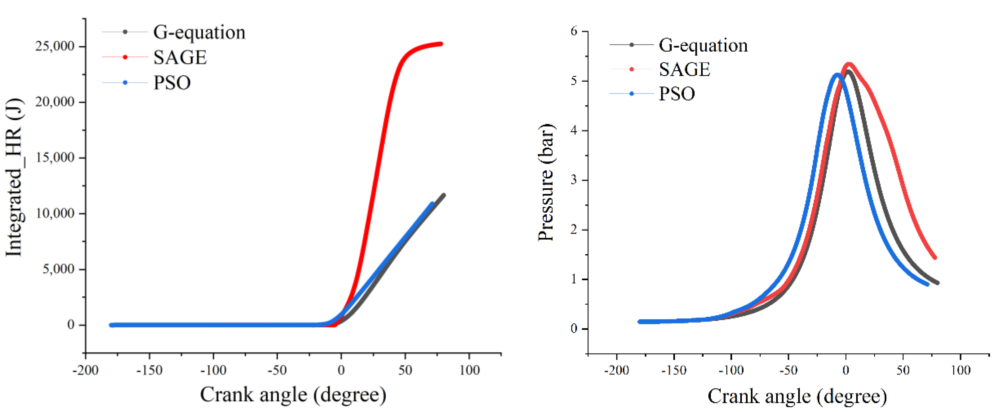
The pre-chamber model was built in Converge CFD software. The SAGE model requires an accurate chemical mechanism, and running it is relatively computationally expensive if the mechanism is large. Meanwhile, the G-equation model is a premixed combustion model that typically runs faster than the detailed chemistry model, and a reaction mechanism may not be required. The G-equation model accounts for turbulent mixing enhancement through the turbulent flame speed closure, but it does not account for the commutation error. Therefore, the G-equation model was chosen as the simulation model in this study. After running the SAGE and G-equation models, it was found that the G-equation model met the requirements of the simulation test.
(2)
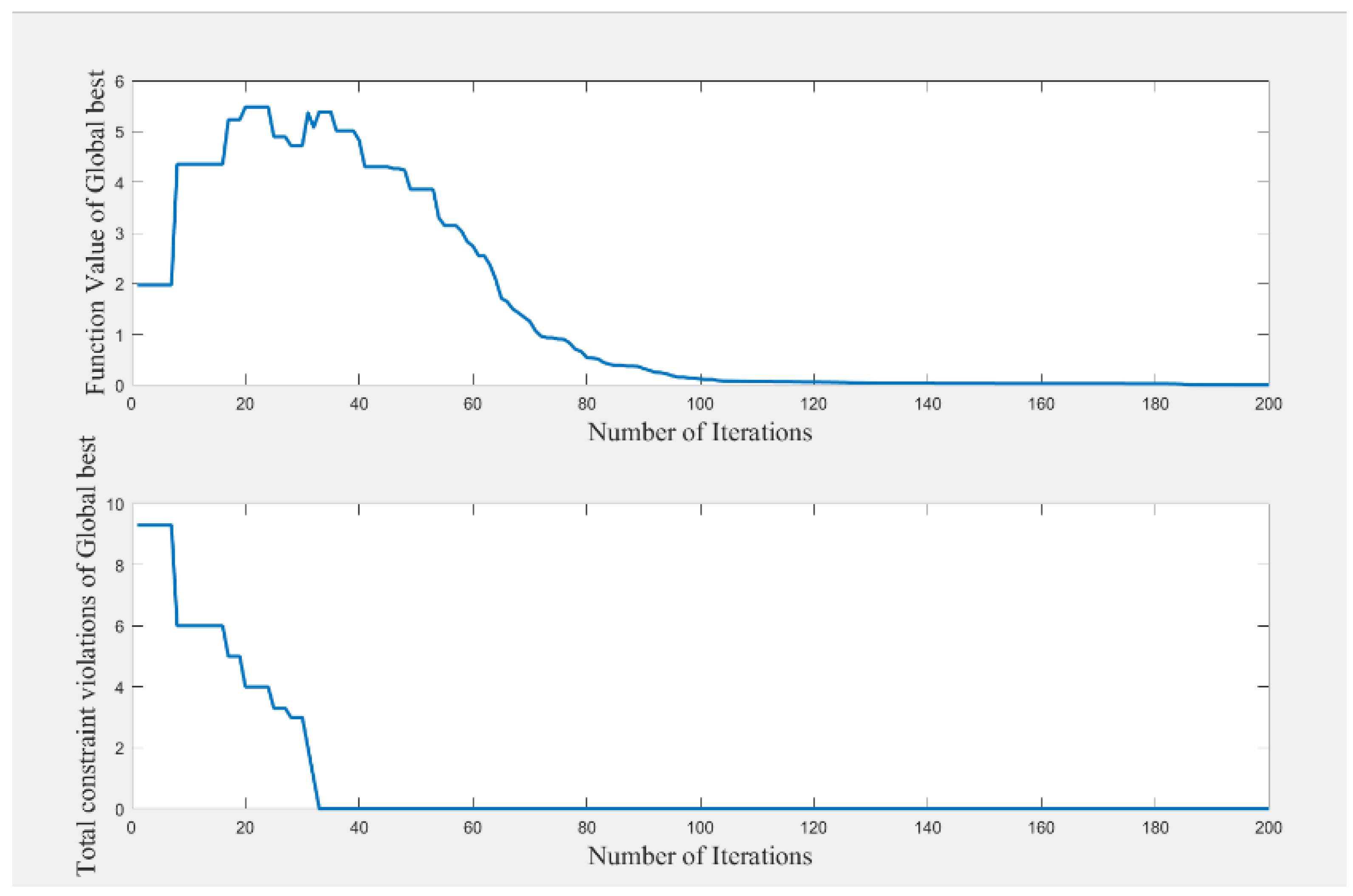
G-equation models with 50 different parameters were randomly generated, numerically simulated, and computed in CONVERGE software. Then, a Kriging proxy model was built from these 50 sets of values for subsequent particle swarm optimization. The PSO optimization algorithm was iteratively calculated with the optimal heat release and pressure as the optimization objectives. The model parameters after optimization by the PSO algorithm were: a 1 = 0.77 , b 1 = 2.0 , b 3 = 1.0 . The optimal G-equation model was obtained for simulation and calculation.
(3)
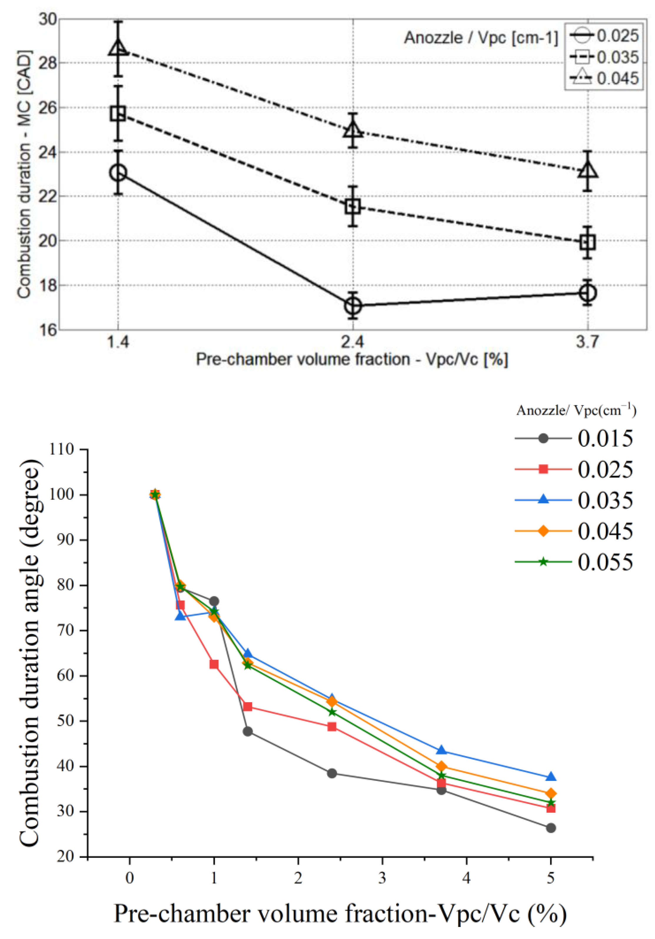
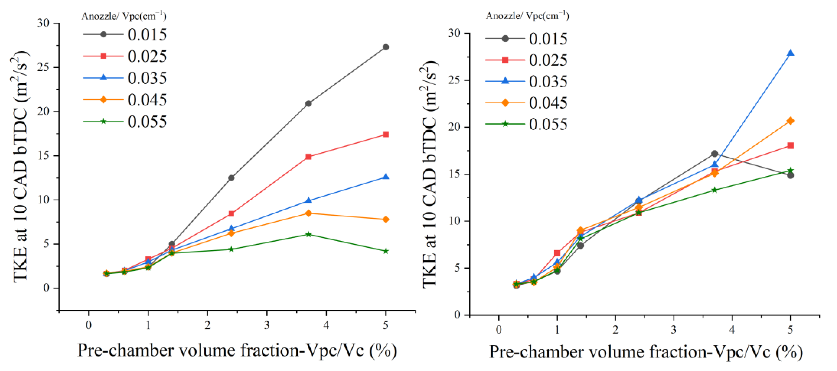
The combustion and emission characteristics of a gasoline engine with a pre-chambered system were investigated numerically using Converge CFD software with different parameters. The comparison of the numerical simulation results with the experimental results of Ashish proved the consistency and validity of this study. It was found that the volume and area ratio of the pre-chamber played a key role in the performance of the pre-combustion chamber. For the pre-combustion chamber with a small volume, the injection velocity decreased with the volume reduction. Small injection velocities resulted in poor gas mixing and, therefore, increased NOx and CO production. When the pre-chamber was small enough, this effect became more obvious. The flame did not spread well from the pre-combustion chamber to the main combustion chamber, which led to a relatively large pressure difference and had a negative effect on the whole combustion process. Through the simulation test observations, we found that the pre-combustion chamber with Anozzle/Vpc = 0.055 reduced the NOx and CO emissions better than the pre-combustion chamber designs in other cases, which provides a reference and suggestion for the design of a pre-chamber system for agricultural machinery.

Author Contributions

Conceptualization, B.Z.; methodology, B.Z.; software, B.Z.; validation, B.Z., Y.L., W.L.; formal analysis, Z.L.; investigation, X.S.; writing—original draft preparation, B.Z.; writing—review and editing, Z.S., Q.Z., E.M.; funding acquisition, Z.S. All authors have read and agreed to the published version of the manuscript.

Funding

This research was funded by the National Key Research and Development Plan of China (2017YFD0700301).

Institutional Review Board Statement

Not applicable.

Informed Consent Statement

Not applicable.

Data Availability Statement

Not applicable.

Conflicts of Interest

The authors declare no conflict of interest.

References

  1. National Bureau of Statistics of the People’s Republic of China. China Statistical Yearbook; China Statistics Press: Beijing, China, 2020.
  2. Attard, W.P.; Hugh, B. A Single Fuel Pre-Chamber Jet Ignition Powertrain Achieving High Load, High Efficiency and Near Zero NOx Emissions. SAE Int. J. Engines 2011, 5, 734–746. [Google Scholar] [CrossRef] [Green Version]
  3. Wu, H.; Wang, L.; Wang, X.; Sun, B.; Zhao, Z.; Lee, C.F.; Liu, F. The effect of turbulent jet induced by pre-chamber sparkplug on combustion characteristics of hydrogen-air pre-mixture. Int. J. Hydrogen Energy 2018, 43, 8116–8126. [Google Scholar] [CrossRef]
  4. Yamanaka, K.; Shiraga, Y.; Nakai, S. Development of pre-chamber sparkplug for gas engine. In Proceedings of the Sae International Powertrains, Fuels & Lubricants Meeting, Kyoto, Japan, 30 August–2 September 2011. [Google Scholar]
  5. De Castro Radicchi, F.; Braga, R.M.; Coelho, R.D.O.A.; da Costa, R.B.R.; Valle, R.M. Numerical Analysis of the Fluid Flow in a Prechamber for a Spark-ignition Engine; Sae Brasil International Congress & Display; SAE International: Warrendale, PA, USA, 2015. [Google Scholar]
  6. Toulson, E.; Schock, H.J.; Attard, W.P. A Review of pre-chamber initiated jet ignition combustion systems. In Proceedings of the SAE 2010 Powertrains Fuels & Lubricants Meeting, San Diego, CA, USA, 25–27 October 2010. [Google Scholar]
  7. Toulson, E.; Watson, H.C.; Attard, W.P. Gas Assisted jet ignition of ultra-lean LPG in a spark ignition engine. In Proceedings of the SAE World Congress & Exhibition, Detroit, MI, USA, 20–23 April 2009. [Google Scholar]
  8. Sens, M.; Binder, E.; Reinicke, P.B.; Riess, M.; Stappenbeck, T.; Woebke, M. Pre-chamber ignition and promising complementary technologies. In Proceedings of the 27th Aachen Colloquium Automobile and Engine Technology, Aachen, Germany, 10–12 October 2018; pp. 957–998. [Google Scholar]
  9. Ricardo, H.R. Recent research work on the internal-combustion engine. SAE Trans. 1922, 17, 1–93. [Google Scholar]
  10. Noguchi, M.; Sanda, S.; Nakamura, N. Development of Toyota lean burn engine. SAE Trans. 1976, 85, 2358–2373. [Google Scholar]
  11. Adams, T.G. Torch Ignition for Combustion Control of Lean Mixtures; SAE Technical Paper; SAE International: Warrendale, PA, USA, 1979. [Google Scholar]
  12. Brandstetter, W. The Volkswagen lean burn pc-engine concept. SAE Trans. 1980, 89, 1804–1821. [Google Scholar]
  13. Gussak, L.A.; Ryabikov, O.B.; Politenkova, G.G.; Furman, G.A. Effect of adding individual combustion products on combustion of methane—Air mixture. Bull. Acad. Sci. USSR Div. Chem. Sci. 1973, 22, 2128. [Google Scholar] [CrossRef]
  14. Gussak, L.A.; Karpov, V.P.; Tikhonov, Y.V. The application of lag-process in prechamber engines. In Proceedings of the Passenger Car Meeting & Exposition, Amsterdam, The Netherlands, 11 June 1979. [Google Scholar]
  15. Maxson, J.A.; Hensinger, D.M.; Hom, K.; Oppenheim, A.K. Performance of Multiple Stream Pulsed Jet Combustion Systems; Lawrence Berkeley National Laboratory: Berkeley, CA, USA, 1990. [Google Scholar]
  16. Toulson, E.; Watson, H.C.; Attard, W.P. The Lean Limit and Emissions at Near-Idle for a Gasoline HAJI System with Alternative Pre-chamber Fuels; SAE Technical Paper; SAE International: Warrendale, PA, USA, 2007. [Google Scholar]
  17. Attard, W.P.; Fraser, N.; Parsons, P.; Toulson, E. A turbulent jet ignition pre-chamber combustion system for large fuel economy improvements in a modern vehicle powertrain. SAE Int. J. Engines 2010, 3, 20–37. [Google Scholar] [CrossRef] [Green Version]
  18. Attard, W.P.; Bassett, M.; Parsons, P.; Blaxill, H. A New Combustion System Achieving High Drive Cycle Fuel Economy Improvements in a Modern Vehicle Powertrain; SAE Technical Paper; SAE International: Warrendale, PA, USA, 2011. [Google Scholar]
  19. Attard, W.P.; Blaxill, H. A Lean Burn Gasoline Fueled Pre-Chamber Jet Ignition Combustion System Achieving High Efficiency and Low NOx at Part Load; SAE Technical Paper; SAE International: Warrendale, PA, USA, 2012. [Google Scholar]
  20. Bunce, M.; Blaxill, H.; Kulatilaka, W.; Jiang, N. The Effects of Turbulent Jet Characteristics on Engine Performance Using a Pre-Chamber Combustor; SAE Technical Paper; SAE International: Warrendale, PA, USA, 2014. [Google Scholar]
  21. Chinnathambi, P.; Bunce, M.; Cruff, L. RANS Based Multidimensional Modeling of an Ultra-Lean Burn Pre-Chamber Combustion System with Auxiliary Liquid Gasoline Injection; SAE Technical Paper; SAE International: Warrendale, PA, USA, 2015. [Google Scholar]
  22. Sens, M.; Binder, E.; Benz, A.; Kramer, L.; Schultalbers, M.; Blumenröde, K. Pre-chamber ignition as a key technology for highly efficient SI engines-new approaches and operating strategies. In Proceedings of the 39th International Vienna Motor Symposium, Vienna, Germany, 26–27 April 2018; pp. 26–27. [Google Scholar]
  23. Sens, M.; Binder, E. Pre-chamber ignition as a key technology for future powertrain fleets. MTZ Worldw. 2019, 80, 44–51. [Google Scholar] [CrossRef]
  24. Hlaing, P.; Echeverri Marquez, M.A.; Singh, E.; Almatrafi, F.A.; Cenker, E.; Ben Houidi, M.; Johansson, B. Effect of Pre-Chamber Enrichment on Lean Burn Pre-Chamber Spark Ignition Combustion Concept with a Narrow-Throat Geometry; SAE Technical Paper; SAE International: Warrendale, PA, USA, 2020. [Google Scholar]
  25. Qin, F.; Shah, A.; Huang, Z.W.; Peng, L.N.; Tunestal, P.; Bai, X.S. Detailed numerical simulation of transient mixing and combustion of premixed methane/air mixtures in a pre-chamber/main-chamber system relevant to internal combustion engines. Combust. Flame 2018, 188, 357–366. [Google Scholar] [CrossRef]
  26. Hua, J.; Zhou, L.; Gao, Q.; Feng, Z.; Wei, H. Influence of pre-chamber structure and injection parameters on engine performance and combustion characteristics in a turbulent jet ignition (TJI) engine. Fuel 2021, 283, 119236. [Google Scholar] [CrossRef]
  27. Biswas, S.; Qiao, L. Prechamber hot jet ignition of ultra-lean H₂/air mixtures: Effect of supersonic jets and combustion instability. SAE Int. J. Engines 2016, 9, 1584–1592. [Google Scholar] [CrossRef] [Green Version]
  28. Biswas, S.; Tanvir, S.; Wang, H.; Qiao, L. On ignition mechanisms of premixed CH4/air and H2/air using a hot turbulent jet generated by pre-chamber combustion. Appl. Therm. Eng. 2016, 106, 925–937. [Google Scholar] [CrossRef]
  29. Shah, A.; Tunestal, P.; Johansson, B. Investigation of performance and emission characteristics of a heavy duty natural gas engine operated with pre-chamber spark plug and dilution with excess air and EGR. SAE Int. J. Engines 2012, 5, 1790–1801. [Google Scholar] [CrossRef]
  30. Shah, A.; Tunestal, P.; Johansson, B. Effect of relative mixture strength on performance of divided chamber avalanche activated combustion ignition technique in a heavy duty natural gas engine. In Proceedings of the SAE 2014 World Congress & Exhibition. Society of Automotive Engineers, Detroit, MI, USA, 8–10 April 2014. [Google Scholar]
  31. Shah, A.; Tunestal, P.; Johansson, B. Effect of Pre-Chamber Volume and Nozzle Diameter on Pre-Chamber Ignition in Heavy Duty Natural Gas Engines; SAE Technical Paper; SAE International: Warrendale, PA, USA, 2015. [Google Scholar]
  32. Toulson, E.; Huisjen, A.; Chen, X.; Squibb, C.; Zhu, G.; Schock, H.; Attard, W.P. Visualization of propane and natural gas spark ignition and turbulent jet ignition combustion. SAE Int. J. Engines 2012, 5, 1821–1835. [Google Scholar] [CrossRef]
  33. Li, F.; Zhao, Z.; Wang, B.; Wang, Z. Experimental study of pre-chamber jet ignition in a rapid compression machine and single-cylinder natural gas engine. Int. J. Engine Res. 2019, 22, 1342–1356. [Google Scholar] [CrossRef]
  34. Moriyoshi, Y.; Morikawa, K.; Kuboyama, T.; Yamada, T. Improvement in Thermal Efficiency of Lean Burn Pre-Chamber Natural Gas Engine by Optimization of Combustion System; No. 2017-01-0782, SAE Technical Paper; SAE International: Warrendale, PA, USA, 2017. [Google Scholar]
  35. Ghirardo, G.; Nygård, H.T.; Cuquel, A.; Worth, N.A. Symmetry breaking modelling for azimuthal combustion dynamics. Proc. Combust. Inst. 2021, 38, 5953–5962. [Google Scholar] [CrossRef]
  36. Yasin, S.; Curti, M.; Rovero, G.; Hussain, M.; Sun, D. Spouted-Bed Gasification of Flame Retardant Textiles as a Potential Non-Conventional Biomass. Appl. Sci. 2020, 10, 946. [Google Scholar] [CrossRef] [Green Version]
  37. Yasin, S.; Massimo, C.; Rovero, G.; Behary, N.; Perwuelz, A.; Giraud, S.; Migliavacca, G.; Chen, G.; Guan, J. An alternative for the end-of-life phase of flame retardant textile products: Degradation of flame retardant and preliminary settings of energy valorization by gasification. BioResources 2017, 12, 5196–5211. [Google Scholar] [CrossRef]
  38. Shah, A. Improving the Efficiency of Gas Engines Using Pre-Chamber Ignition; Division of Combustion Engines, Department of Energy Sciences, Faculty of Engineering, Lund University: Lund, Sweden, 2015. [Google Scholar]
  39. Kennedy, J.; Eberhart, R. Particle swarm optimization. In Proceedings of the ICNN’95-International Conference on Neural Networks, Perth, WA, Australia, 27 November–1 December 1995; Volume 4, pp. 1942–1948. [Google Scholar]
  40. Feng, J.; Wang, Y.; Wang, Q.; Xu, B. Fast reflector self-anti-disturbance control based on improved particle swarm algorithm. Syst. Eng. Electron. 2021, 12, 3675–3682. [Google Scholar] [CrossRef]
Figure 1. Geometry of the test engine.
Energies 15 04506 g001
Figure 2. Initiation and development of the flame in the main chamber.
Energies 15 04506 g002aEnergies 15 04506 g002b
Figure 3. Flow chart of the PSO algorithm.
Energies 15 04506 g003
Figure 4. Optimization iterative diagram.
Energies 15 04506 g004
Figure 5. Integrated amount of heat release and pressure trace in the main chamber.
Energies 15 04506 g005
Figure 6. Laminar flame speed (m/s) and velocity fluctuation in the pre-chamber.
Energies 15 04506 g006
Figure 7. Main chamber flame development angle for different excess air ratios in the pre-chamber and main chamber [35].
Energies 15 04506 g007
Figure 8. Extended range of simulations with different working conditions: (a) volume ratio 0.6%; nozzle area ratio 0.015 cm−1; (b) volume ratio 0.6%; nozzle area ratio 0.035 cm−1; (c) volume ratio 2.4%; nozzle area ratio 0.015 cm−1; (d) volume ratio 0.6%; nozzle area ratio 0.035 cm−1.
Energies 15 04506 g008
Figure 9. Simulation results of main chamber FDA vs. results from Ashish [24].
Energies 15 04506 g009aEnergies 15 04506 g009b
Figure 10. Simulation results of main chamber combustion duration vs. results from Ashish.
Energies 15 04506 g010
Figure 11. TKE at 10 CAD before and after TDC.
Energies 15 04506 g011
Figure 12. Increase in the mixing ratio in the main chamber.
Energies 15 04506 g012
Figure 13. Emission generation in the engine.
Energies 15 04506 g013
Table 1. The test engine specifications.
ItemValue
Engine Cylinder Bore0.2 m
Engine Cylinder Stroke0.28 m
Engine Squish Height0.0001 m
Engine Connecting Rod Length0.51 m
Engine Speed (RPM)800.0
Engine Displacement8.8 L
Compression Ratio12
Table 2. Test grid for optimal design of pre-chamber.
An/Vpc0.015 cm−10.025 cm−10.035 cm−10.045 cm−10.055 cm−1
Vpc/Vc
0.3%2.20.722.20.942.21.112.21.262.21.39
0.6%4.41.024.41.324.41.574.41.784.41.96
1.0%7.31.327.31.717.32.027.32.297.32.53
1.4%10.31.5710.32.0210.32.3910.32.7110.33.00
2.4%17.62.0517.62.6517.63.1317.63.5517.63.99
3.7%27.12.5527.13.2927.13.8927.14.4127.14.87
5.0%36.72.9636.73.8236.74.5236.75.1236.75.67
Publisher’s Note: MDPI stays neutral with regard to jurisdictional claims in published maps and institutional affiliations.

