1. Introduction
The need to improve the energy efficiency of residential and public buildings makes research into the thermal properties of modern double-glazed windows essential. It should be noted that the technical condition of most existing buildings does not allow the required level of energy efficiency to be achieved. Among building components, windows are the most problematic in terms of heat loss, generating 20–40% of total heat loss in residential buildings [
1,
2]. So, replacing them with modern double-glazed windows, and thus improving thermal resistance, increases the energy efficiency of the building by 20–30%. Minimizing heat loss while maintaining large areas of glazing to provide natural light [
3,
4,
5] is one of the key issues related to sustainability, modern architecture and indoor thermal comfort.
Heat transfer in windows occurs due to conduction through the glass, convection occurs in the gaseous medium filling the gap between the panes and radiation. Therefore, a reduction in the heat transfer coefficient of windows can be achieved by minimizing the convective and radioactive components, which has been the subject of numerous scientific studies. The influence of the air layer thickness and the temperature difference between the panes on the thermal resistance of a double-pane window was presented in [
6,
7]. The results showed that both the convective heat transfer coefficient and the overall heat transfer coefficient for the whole window increase linearly with the temperature difference between the panes. The thermal resistance also changes with the air layer thickness between the panes up to a gap width of 25 mm. If the air gap width exceeds 25 mm, the window’s heat transfer coefficient remains almost constant.
An analysis of heat transfer through a double-glazed window, taking into account convection in the gaps and conduction in the panes in the mathematical model, neglecting radiation, has been carried out in [
8,
9]. The aim of the study was also to determine the effect of the gap width between the panes on the average Nusselt number and to select its optimum value. Two different types of boundary conditions were used for the external pane surfaces: steady-state temperature and convective flow. In the first case, the temperatures of the two glass surfaces were assumed to be equal to the design internal and external winter temperatures. In the second case, a convection condition was determined for the external surfaces of the window panes. It has been found that energy losses through double-glazed windows can be significantly reduced by optimizing the gap width or replacing air with a gas with lower thermal conductivity. For smaller gap widths, the Nusselt number is about 1, indicating that heat transfer by convection and conduction occurs at a similar level. With larger gap widths (more than 12 mm), the Nusselt number increases because the decrease in heat transfer due to thermal conduction is offset by a significant increase in heat transfer due to natural convection.
In [
10,
11,
12,
13], mathematical modeling of heat transfer in windows was also carried out, taking into account the different width of the gap between the panes (6 mm, 9 mm, 12 mm, 15 mm and 18 mm) for double-, triple- and quadruple-pane windows and the influence of different emissive coatings and gas filling on the heat transfer intensity. Based on the results obtained, a correlation was presented to predict the value of the heat transfer coefficient. The results showed that the value of the heat transfer coefficient also decreases with increasing gap width. The mechanism of heat transfer in gaps between the panes depends significantly on their width, and the drop in the value of the heat transfer coefficient is insignificant with a gap width greater than 12 mm. At its value of 6 mm, the gas flow velocity is low, so heat transfer by convection is negligible. In this case, the Nusselt number (except for the bottom and top of the window) is about 1, so heat transfer occurs equally by heat convection and conduction. As the gap width increases, the importance of convection, and consequently, the Nusselt number also increases. At this stage, it is observed that the Rayleigh number exceeds 6300, causing changes in flow and degradation of the linearity of the temperature profiles. Thus, the drop in the heat transfer coefficient is insignificant when the gap width is greater than 12 mm.
Nusselt numbers for forced convection [
14], occurring between symmetrically heated parallel plates with the same surface temperature, have been adapted for use in ventilated windows whose panes have different surface temperatures due to the supply of warm air and the large temperature difference between the inside and the outside [
12]. For this reason, the constant value in the original Nusselt number correlations was changed to more accurately account for the effect of asymmetrically heated windows. This important difference in the boundary condition was also considered in [
15,
16] and values of Nusselt numbers were suggested for symmetrically and asymmetrically heated parallel planes with uniform surface temperatures. The Nusselt number for panes with asymmetric surface temperatures is about 1.9 times lower than for panes with the same surface temperatures [
12]. In a ventilated window, the influence of the gap width on the value of the heat transfer coefficient turns out to be insignificant, while the change in the temperature of the supplied air is significant. In order to maintain a low heat transfer coefficient, the temperature of the air supplied to the window must be higher than the room’s internal temperature.
The authors of [
17] proposed a mathematical model to simulate solar radiation incidents on any window plane and the corresponding temperatures on the pane surfaces on any day of the year. A thermal model of heat transfer through the window was also prepared for both the inner and outer surfaces of the panes, taking into account conduction, convection and radiation. Depending on the atmospheric changes outside and the changes in the indoor environment related to the seasons, different types of convection were taken into account. During the summer months, when internal air circulation is by means of a ceiling fan, a forced convection process is included for both the internal and external pane surfaces. On the other hand, in the winter months, the process of free convection on the inner surface of the panes and forced convection on the outer surface at low air velocity were considered. The study analyzed the optical and thermal properties of windows, assessed the effect of solar radiation through the window on heat gains inside the building, and compared the results with experimental values. Estimated errors between experimental and analytical values of incident radiation on window planes and pane temperatures were shown to be within ±5%.
In the papers cited above, all factors affecting the thermal resistance of windows are analyzed, but the proposed results only concern specific window structures and only allow the qualitative and quantitative influence of these parameters on the intensity of heat transfer to be assessed.
The total heat flux through transparent dividing structures is therefore dependent on the difference in internal and external temperatures, on solar radiation independent of the temperature of the outside air and the indoor air, on infiltration of outside air passing through leaks in the windows, and on their dimensions and geometry.
The papers cited, and those of many other authors, present interesting data characterizing the mutual influence of the above-mentioned factors, but no generalized mechanism for increasing the thermal resistance of transparent dividing structures is proposed. It is possible to propose such a solution by developing a comprehensive mathematical model, which is the subject of this paper.
2. Evaluation of Heat Transfer Rates through Window Structures
An important parameter for characterizing the thermal properties of windows is the heat transfer coefficient U, which defines the heat flow through 1 m2 of the dividing structure surface with a temperature difference on both sides (Tin − Tout) = 1 K. The inverse of the heat transfer coefficient is thermal resistance, expressed by the formula Rt = 1/U.
There are two methods for determining the heat transfer coefficient U: experimental research on a specific dividing structure, which is carried out in a climatic chamber or in natural conditions, and mathematical modeling of heat transfer processes using modern computer programs. Experimental research is quite lengthy and expensive, and is therefore carried out at the final stage of the studies conducted. For preliminary research and evaluation of energy efficiency of windows it is advisable to use methods of mathematical modeling of heat transfer processes in transparent dividing structures, which determines, with high accuracy, the thermal properties of windows as a whole as well as their individual components [
18,
19]. The advantage of mathematical modeling is not only the financial savings, but also the possibility of using it at the design stage to achieve the desired thermal properties of windows.
Among the simplest but effective models for determining the thermal properties of window structures is the one-dimensional heat transfer model, based on the basic laws of conduction, convection and radiation.
For double-pane windows, with a one-dimensional formulation and boundary conditions of the third kind on the pane surfaces, without taking into account solar radiation and infiltration, the thermal resistance of the window is given by the formula:
where
αin and
αout are the convective heat transfer coefficients on the surfaces of panes;
αgj is the effective heat transfer coefficient in the gap between the panes in a double-glazed window,
δj is the thickness of panes in a double-glazed window,
λj is the thermal conductivity of panes, and
n is the number of panes.
For cases with a small gap width (
b < 10 mm), the heat transfer by convection is insignificant due to the low values of the velocity of free convective gas flow. If it is fashionable to neglect convection, then under boundary conditions of the first kind on the outer surfaces of a double-glazed window, the formula for calculating its thermal resistance takes the form:
where
ε1 and
ε2 are the emissivity of the inner surfaces of the panes;
λair is the thermal conductivity of the air layer in the gap between the panes of a double-glazed window;
is Stefan–Boltzmann constant
= 5.67·10
−8 W/(m
2·K
4).
For windows in which the width of the air gap between the panes
b does not exceed 10–12 mm, the value
αgj can be calculated from the formula:
In this case, the effect of natural convection on heat transfer in the gap between the panes is not taken into account. However, at
b > 12 mm, neglecting the convective component can lead to significant errors. For such cases, in the formula for thermal resistance, the authors of [
20,
21] propose that the convection in the vertical gap between the panes can be taken into account by replacing the value of the gas thermal conductivity by
λeqv:
where
Ra is the Rayleigh number,
v is the kinematic viscosity coefficient;
a is the thermal diffusivity of the gas;
Tav is the average temperature of the gas filling the gap between the panes,
g is the acceleration due to gravity.
The values of the numerical coefficients in Equations (4) and (5) have been revised and corrected [
22,
23,
24,
25,
26], and the window heat transfer equations have been clarified by taking into account heat flux through the frame profile, additional chambers in double-glazed windows, etc.
Among the one-dimensional models used to assess the thermal performance of modern double-pane windows, the WindowsN and VISION computer systems developed in the USA and Canada occupy a special place [
22,
23,
24,
27]. These programs calculate almost all thermal characteristics of window structures. One-dimensional methods and the computer programs based on them, enable rapid assessment of the advisability of using specific technical solutions for window structures. However, as shown in [
25], calculations with one-dimensional methods can differ from two-dimensional solutions by 6–10%.
In addition, one-dimensional methods make it impossible to take into account the asymmetry of the temperature field associated with heat flux through the pane and with air convection in the gap between the panes in a double-glazed window. At the same time, one-dimensional solutions make it impossible to take into account the flow regime in the space between the panes, which determines the convective component of the heat flux, and also cannot accurately determine the magnitude of the radiation flux, which depends on the optical properties of the surface through which the heat transfer takes place.
The disadvantages of one-dimensional models listed above can be eliminated by using a two-dimensional representation of the heat transfer problem through transparent dividing structures.
In this paper, a two-dimensional model of heat transfer through a double-pane window was considered.
Figure 1 shows a geometric model of a double-glazed window with height
H. The gap between the panes is filled with air. Boundary conditions of the first kind are established on the outer surfaces of the panes with defined temperature values
Tout and
Tin. A fourth kind of boundary condition is established on the inner surfaces of the pane, which limits the gap between the panes. The lower and upper edges of the window are treated as adiabatic boundaries.
Reducing heat transfer by convection and conduction through a double-glazed window can be achieved both by varying the distance between panes b at a fixed value of H, and by replacing the air in the gap between the panes with an inert gas (for example argon) which has a lower thermal conductivity than air. The reduction in the radiative component of the heat flux takes place by applying special selective coatings with a low emission coefficient to the inner surfaces of the panes of the window.
As shown in the cited works, the regime and structure of the gas flow in the gap between the panes, as well as the thermal resistance of the transparent part of the double-glazed window, depends on the thickness b and the height H of the gap between the panes; the temperature difference ΔT = Tin − Tout; the inclination angle of the double-glazed window to the horizontal surface; and the thermal properties of the panes and the gas layer filling the gap between the panes.
4. Results
Computational studies were carried out using the StarCCM and Fluent CFD packages to determine the effect of the gap between the panes’ width b and the mode of airflow during natural convection on heat transfer through a double-glazed window of height H = 1.06 m at Tin = 15 °C and Tout = −22 °C. The change in width b was considered in the range of 0.01 m to 0.1 m.
Figure 2 shows the air velocity fields during natural convection in the gap between the panes for different values of
b. The corresponding values of the Rayleigh number (6) and thermal resistance
Rt of the double-glazed window are also given.
where
qtot is the heat flux from the room to the environment, taking into account radiation, convection and conduction.
As shown in
Figure 2, for variants with a gap width
b < 0.012 m, the flow during natural convection is cyclic; near warmer surfaces there is an upward flow and near cooler surfaces, downward flow is observed. For cases with
b values of 0.011–0.012 m, the flow structure changes. Over the entire height of a double-pane window, local, periodically recurring vortexes develop in the gap between the panes.
As the distance between panes increases, the areas occupied by vortex are stretched. At
b = 0.03 m, a small area of low-moving air appears between the layers of gas adjacent to the glass (
Figure 2), separating the ascending and descending flows near the glass. As
b increases further, the large vortexes disappear and the airflow becomes cyclic again, which is consistent with the main assumptions of the theory of gas flow in vertical channels.
Changes in the flow structure in the slotted canal have also been indicated in [
21,
22]. In paper [
20], the occurrence of vortexes in gaps with a relatively short distance between the panes is explained by the interaction of boundary layers formed on opposite walls, in the vicinity of which the gas flow is multidirectional.
Chaotic, moving vortex rolls during convection, due to temperature differences in the case of low Prandtl numbers, have been experimentally observed using ultrasonic methods for liquids, in particular for mercury [
28].
From the results obtained in this study, it is evident that the cyclic nature of the flow occurs in gaps with a relatively short distance between panes. The formation of local vortexes was observed at b > 0.012 m. However, the flow structure in the gap is affected not only by its cross-sectional dimension, but also by other factors.
In natural convection, the fluid flow regime is determined by the corresponding Rayleigh number. In order to determine the critical Rayleigh number, which establishes the transition from a cyclic to vortexes flow regime, numerical investigations were carried out for different models of single-, double- and triple-chamber double-glazed windows made of standard transparent glass.
Flow regimes for double-glazed windows were considered for the variants:
- -
with different distances between the panes,
b, from 0.01 to 0.1 m, at constant height
H = 1.06 m and temperature difference Δ
T =
Tin −
Tout = 37 °C (
Figure 2);
- -
with different heights H, from 0.375 m to 2 m, at constant b and ΔT;
- -
with different internal (Tin from 5.15 to 20 °C) and external (Tout from 0 to −20 °C) pane surface temperatures, with constants b and H;
- -
with different window angles β from 0 to 90°, at constant b, ΔT and H.
Figure 3 shows the results of calculations of thermal resistance of a double-pane window with a thickness between the panes
b = 0.015 m, height
H = 1.06 m,
Tin = 15 °C, depending on the outdoor temperature
Tout.
The change in airflow regime in the gap between the panes occurs when the ambient temperature changes from Tout = −1 to Tout = −0.5 °C. In this case, the Rayleigh number changes from Ra = 6060 to Ra = 5860, respectively.
The change in airflow structure with a change in the inclination angle of the double-glazed window
β from 0° to 90° is also extremely important (
Figure 4). A variant of the double-glazed window was chosen as the basis for mathematical modeling, in which a stable cyclic flow was observed with a vertical arrangement (with an inclination angle of
β = 90°). As can be seen in
Figure 4, as the inclination angle of the double-glazed window increases from the horizontal (0°) to the vertical position, the airflow structure in the gap between the panes transforms from the flow observed in Rayleigh–Benard cells to cyclic flow. The transition from one flow regime to the other occurs when the inclination angle
β varies from 27 to 30°. There is also a jump in thermal resistance values in this range (
Figure 5).
As a result of numerical study, the range of the critical value of the Rayleigh number in which the transition of airflow from cyclic to vortex occurs in the gap was determined:
As the width of the gap between the panes increases, the airflow changes in the opposite direction; the vortexes gradually begin to extend (
Figure 2) and, with a gap width of
b = 75 mm, non-overlapping boundary layers form at the vertical surfaces of the panes, with an area of stationary air between them.
However, the method of transition from vortexes to cyclic flow is specific. The calculations show that already at
b = 22.5 mm the vortexes’ flow starts to lose stability, and we can say that the problem becomes essentially non-stationary.
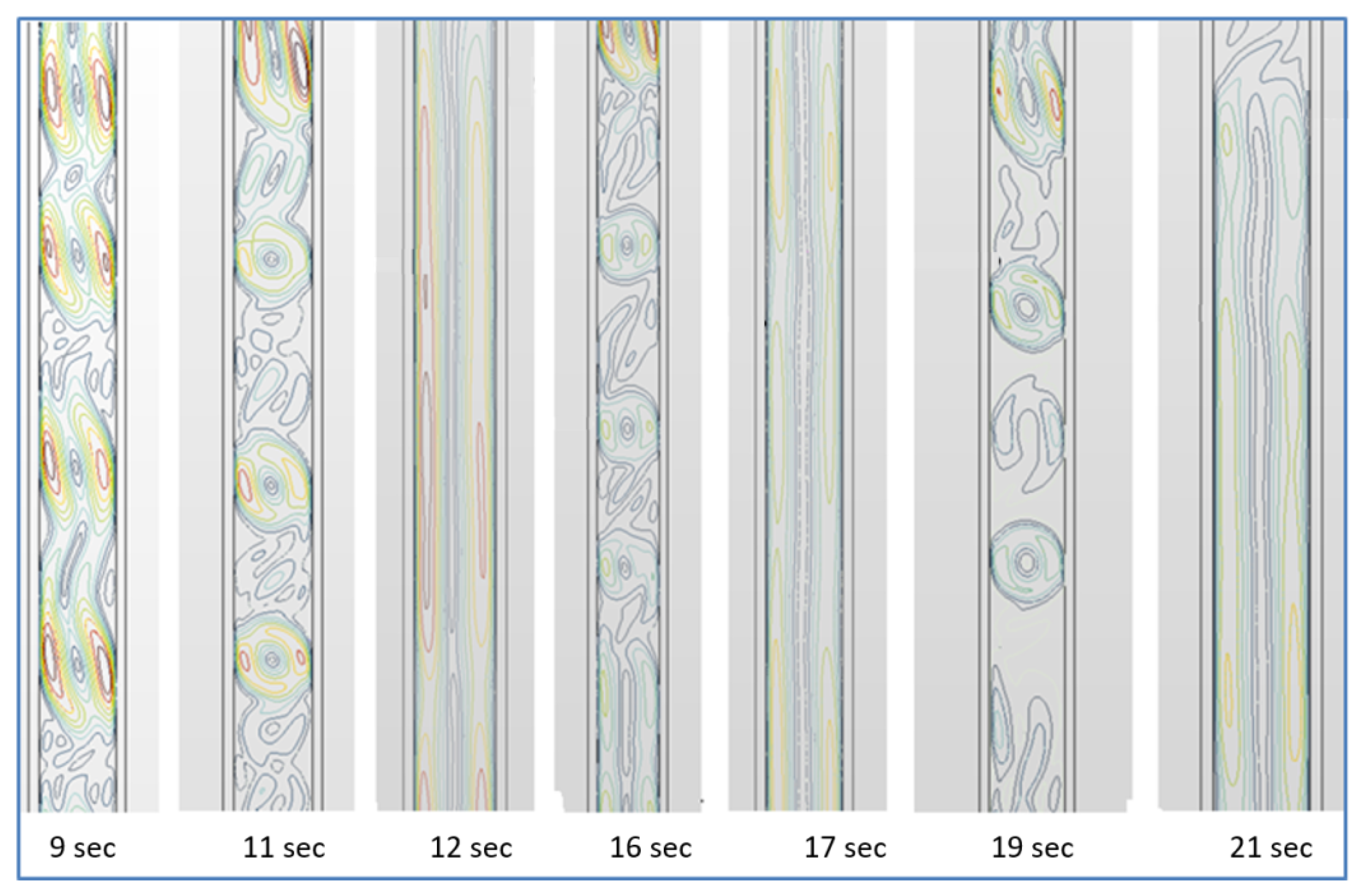
Figure 6 shows the airflow velocity fields in the gap between the panes of a double-glazed window with
H = 1.06 m and Δ
T = 37 °C. As can be seen from the figure, the airflow in the gap is extremely unstable: a vortex forms, disappears and cyclic flow boundary layers form again. At the same time, there are significant variations in the thermal resistance values of double-glazed windows. Moreover, no periodicity of these changes has been noted. Therefore, starting from
b = 22.5 mm, the thermal resistance
Rt was calculated by averaging the thermal resistance values. At
b > 50 mm, vortexes disappears and stable boundary layers form in the gap along the vertical pane surfaces (
Figure 2).
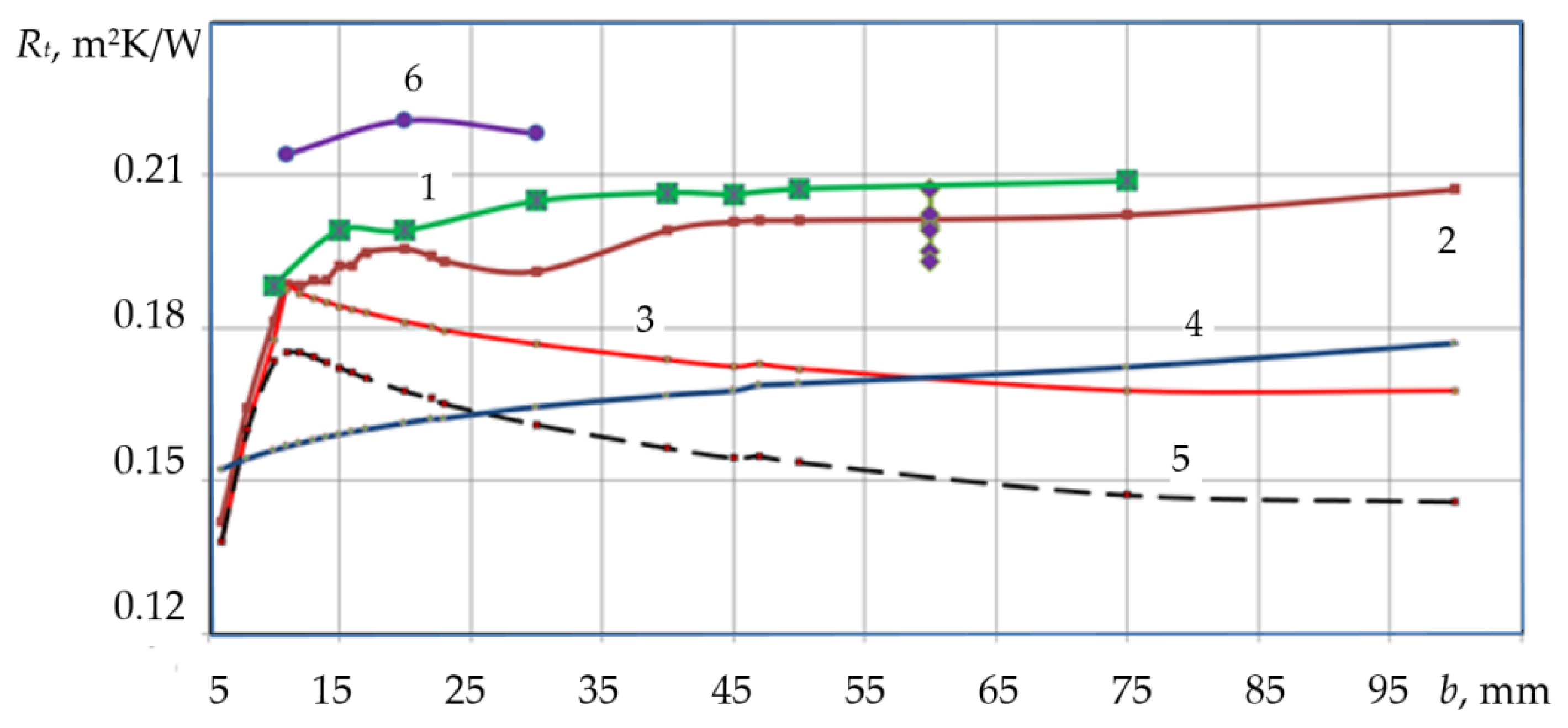
The graph in
Figure 7 shows the thermal resistance values obtained by numerical modeling of the heat transfer process through double-glazed windows made of standard clear glass. At
b < 0.011 m, a sharp increase in thermal resistance is observed with increasing gap width
b. The most rapid increase in the function
Rt =
f(
b) is due to the decrease in conduction heat flux. In the two-dimensional model, after the sudden appearance of vortexes flow in the channel (at
b = 0.012 m), the rapid increase in thermal resistance almost completely ceases (curves 1 and 2,
Figure 7). The cessation of the growth of thermal resistance is due to an increase in the convective component of the heat flux caused by the vortex mode of air flow.
At the same time, the one-dimensional models (curves 3 and 5 in
Figure 7) show a decrease in thermal resistance, and the one-dimensional model [
20] (curve 4) maintains an increasing trend of the function
Rt =
f(
b). The differences between the
Rt values obtained from the one-dimensional and two-dimensional models are 13–14% (curve 3—WINDOWS model), 8 –16% (curve 4—model [
20]), 24% (curve 5—ASHRAE model). The data presented in [
20] indicates that the maximum thermal resistance in the function curve
Rt =
f(
b) occurs in the area
b = 0.012 m, which coincides with the calculations carried out in this paper using one-dimensional models (curves 3 and 5).
Figure 8 shows an extract from
Figure 7, detailing experimental data on heat transfer through a double-glazed window.
Figure 8 shows fairly good agreement between the experimental data and the data obtained from modeling using StarCCM and ANSIS Fluent. The maximum difference between experimental results and calculated values does not exceed 5%.
Verification of the models was carried out according to our own experimental data obtained in real building operation conditions. The experiments were carried out for the old single-chamber window 4M1-60-4M1 (low energy efficiency), installed back in 1973, and for modern double-glazed windows of various types, in particular, type 4M1-10-4M1-10-4M1, installed on a special range of modern window structures of the Institute of Engineering Thermophysics of the National Academy of Sciences of Ukraine, as well as in a full-scale experimental passive house “zero–energy” located at the Institute.
Figure 9 shows a typical fragment of daily (21 February 2015) measurements of temperature and heat flux in the center of the glass of the old window (according to the scheme, inset in
Figure 8) from a series of experiments for the period 20 February–15 March 2015. The window was installed in the center facade of the second floor of a three-story administrative building. The orientation of the window is strictly to the South. During the experiments, there were no personnel in the technical room corresponding to the window. The standard heating system was in operation. There were no other heat sources.
The measurements and archiving of data for each parameter on a PC were performed automatically, one measurement every 10 min, 144 points per day. The methodology for conducting the experiment and processing its results is given in [
29]. The temperature was measured by platinum (sprayed) resistance thermometers; the heat flow was measured by certified sensors of our own original design, which were a battery of microthermocouples with numerous junctions. The total error in temperature measurement was 0.1 °C, and for the heat flux was 1 W/m
2 and sensitivity was 0.2 W/m
2. The temperature sensor was built into the center of the heat flux sensor located in the center of each surface of the two pieces of glass, and its dimensions were ø100 × 2 mm.
The day was conditionally sunny, the sky was cloudy at times with clouds, air humidity was quite high (average per day—87%), the pressure was 762 ± 1 mm Hg. Art., wind velocity ranged from 3 to 5 m/s (average per day—4.3 m/s at a height of 10 m), and the wind direction was from the South, which manifested itself in the dynamics of the parameters measured in the daytime from 9 to 16 h. Negative values of the heat flux show that in the middle of the day there were moments when, under the influence of insolation and wind, the heat flux was directed from the outside (from the environment of the building) into the building.
To verify the model from the presented data, only the range of 0–6 h and 19–22 h, when there was no insolation (direct and diffuse) and the temperature of the ambient air was constant, was used. For these ranges, the average values of the thermal characteristics are given in
Table 1.
The temperature t1 is somewhat higher (on average by 0.6 °C) than the values t2, and the temperatures t3 and t4 practically coincide. The dynamics of all heat fluxes is accompanied by their fluctuations due to changes in the velocity of air movement inside the room, between the window panes and, especially, outside the building. In this case, the average heat fluxes at the inner and outer surfaces of each of the window panes practically coincide within the measurement error. However, the amplitude of the fluctuations in the heat flux q4 is 2.5 times greater than that of the other fluxes q. This is because of fluctuations in the outdoor air flows due to a significant South wind, the direction of which is perpendicular to the South window. The values of the heat fluxes through the outer glass of the window are approximately 2–3 W/m2 less than the fluxes through the inner glass, which means that there is a heat sink in the wooden window frame. Note also that some maximum fluxes, q2 and q4 reached 40 W/m2 in the middle of the day. These few points are not represented on the graph.
Continuous experimental studies of the thermal characteristics of a two-chamber window in the period 28–31 March 2013 are shown in
Figure 10. Index 1 in the figure refers to the center of the glass in the room, and 2 refers to the same position of the outer glass. To verify the models, data were selected from time intervals when there are no personnel in the room. There is also no insolation. The heat fluxes—entering the window
q1 and leaving at
q2—practically coincide within the limits of the fluctuations caused by changes in the velocity of air flows, i.e.,
q1 ≈
q2. Basically, these are time intervals at night between 20.00 p.m. and 6.00 a.m. the next day. The weather conditions were: 28 March—mostly cloudy sky with solar clearings, wind; 29 March—sunny; 30 March—cloudy, it rained at times, 31 March—cloudy. On all days, the wind velocity was up to 3–4 m/s
Figure 11 shows a comparison of the calculated and experimental values of the thermal resistance of a double-pane window with gap widths b of 10, 13 and 15 mm.
The data presented in
Figure 11 shows good agreement between the experimental and computational results. As in the case of a double-glazed window, the difference in these values does not exceed 5%. The combination of computational and experimental results correctly verifies the proposed heat transfer models and confirms the adequacy of the data obtained by calculation to the actual operating conditions of the composite windows.


 ,
, 


