
Artificial Intelligence-Based Protection for Smart Grids
by
 , , , and
Mostafa Bakkar
1,* ,
,
Santiago Bogarra
1 ,
,
Felipe Córcoles
1,
Ahmed Aboelhassan
2 ,
,
Shuo Wang
2 and
Javier Iglesias
3 1
Department of Electrical Engineering, Universitat Politècnica de Catalunya (UPC), C. Colom 1, 08222 Terrassa, Spain
2
Key Laboratory of More Electric Aircraft Technology of Zhejiang Province, University of Nottingham Ningbo China, Ningbo 315100, China
3
ABB Power Grids Spain S.A.U., San Romualdo 13, 28037 Madrid, Spain
*
Author to whom correspondence should be addressed.
Energies 2022, 15(13), 4933; https://0-doi-org.brum.beds.ac.uk/10.3390/en15134933
Submission received: 24 May 2022
/
Revised: 16 June 2022
/
Accepted: 28 June 2022
/
Published: 5 July 2022
Abstract
:Lately, adequate protection strategies need to be developed when Microgrids (MGs) are connected to smart grids to prevent undesirable tripping. Conventional relay settings need to be adapted to changes in Distributed Generator (DG) penetrations or grid reconfigurations, which is a complicated task that can be solved efficiently using Artificial Intelligence (AI)-based protection. This paper compares and validates the difference between conventional protection (overcurrent and differential) strategies and a new strategy based on Artificial Neural Networks (ANNs), which have been shown as adequate protection, especially with reconfigurable smart grids. In addition, the limitations of the conventional protections are discussed. The AI protection is employed through the communication between all Protective Devices (PDs) in the grid, and a backup strategy that employs the communication among the PDs in the same line. This paper goes a step further to validate the protection strategies based on simulations using the MATLABTM platform and experimental results using a scaled grid. The AI-based protection method gave the best solution as it can be adapted for different grids with high accuracy and faster response than conventional protection, and without the need to change the protection settings. The scaled grid was designed for the smart grid to advocate the behavior of the protection strategies experimentally for both conventional and AI-based protections.
1. Introduction
The penetration of MicroGrids (MGs) will be widely acknowledged as a critical technology for integrating Distributed Generators (DGs) in the Distribution System (DS) [1,2], specifically with the widespread new loads such as the 5G communication channel, and the increase in electric vehicle production, auto-drive vehicles, and smart homes [3,4,5]. This means most of the electricity is covered by different types of DGs to form MGs.
Grid codes [6] require power converters to keep injecting power during grid faults to support the grid by decreasing the active power and elevating the reactive power injections [7,8]. Therefore, the need for a protection strategy for smart grids has become more essential. However, many obstacles exist [9], which impacts the Protective Devices (PDs) settings [8]. By using smart protection technologies, the efficiency of these networks can be significantly improved [10].
Various techniques for locating and detecting faults in DSs with DG have been developed. As seen in Table 4 of [11], these approaches can be subdivided into two classes: conventional or Artificial Intelligent (AI) strategies [10]. The limitations of conventional protection strategies are addressed in [12]. These limitations include a change in the power flow resulting in unpredictable operating times. In addition, increasing the penetration of DGs into the MGs results in a wide range of fault levels leading to protection blinding and false tripping [13]. In [14], various DS protection strategies were proposed to utilize the advantages of the DG entirely. The common protection challenges associated with integrating DG into DSs were discussed in [15,16]. A comparison between different fault classification methods was presented in Table 4 of [14]; in addition, a comparison between AI techniques is presented in Table 3 of [17], and the protection schemes for MGs are presented in Table 4 of [17].
Current research trends indicate that the addition of MG threatens conventional protection, such as overcurrent and differential protections, so settings and parameters need to be updated. Traditional protection mechanisms have evolved into new features as a result of standards like IEC 61850 and Ethernet-based communication capabilities, and as a result of utilizing Multi-Agent System (MAS) [18,19] or wireless networks [20]. A two-terminal pilot channel can be used to reduce the communication cost by employing a multi-terminal current differential protection scheme. It should be noted that previous studies have focused on the non-based inverter DS. One of the main concepts in smart grids is the evolution of a centralized controller with Differential Relay (DR). In [20,21], the theory of a hybrid protection scheme was presented, which employs the traditional DR alongside the adaptive one via a central controller for a PV-based inverter system. However, the system was not tested with high PV penetration nor with high fault resistance.
Unlike conventional protections, smart protection techniques can locate the fault for any fault resistance or load consumption even when the grid can be reconfigured. It can be concluded, from Table 1 of [16], that few studies have investigated the protection system behavior with high DG-based inverter penetration [22,23,24,25,26,27].
None of the previous studies used a coordination system with the directional relay system through Artificial Neural Networks (ANNs). The AI protection scheme is based on two strategies. The first strategy is the Centralize Controller (CE) to employ the communication between all PDs in the grid. The second strategy, named Zone Controller (ZO), functions as a backup strategy depending on the communication among the PDs in the same line. This protection strategy makes it possible to locate and isolate symmetrical and unsymmetrical faults. In addition, it considers the changing load consumption, DG penetration, different fault locations, HV/MV transformer configuration, and low and high fault resistance to offer more stable and redundant protection [28].
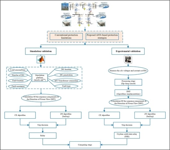
It should be noted that this paper is an evolution of the authors’ previous work regarding overcurrent protection through ANNs for smart distribution networks [28]. It goes a step further in two main branches; on the one hand, we studied the behavior of the conventional and the proposed protection algorithms when MGs are connected to a DS with low short circuit power. In addition, a comparison of these protection algorithms is provided and validated experimentally. On the other hand, the effectiveness of the proposed AI-protection strategy is illustrated and compared with two conventional protection strategies, Overcurrent Relay (OCR) and DR. In the authors’ previous work, the analysis was carried out by sending the data of the faulted line from the dSPACE to be managed through the Digital Signal Processor (DSP) controller. The data of the healthy lines were set within the DSP controller to check the performance of the solid-state relay. However, we designed a scaled system for the Medium Voltage (MV) DS and this was implemented experimentally in the laboratory. The behavior of the proposed protection algorithms was demonstrated and analyzed experimentally, considering the whole grid without using data generated from the dSPACE. In this case, the dSPACE was used only to control the inverter of the DG.
The rest of the paper is organized as follows: the challenges of using the conventional and AI-based protection techniques with MGs is clarified in Section 2. Section 3 explains the proposed protection strategy. Then, a comparative study is developed between the OCR, DR conventional relays, and the proposed protection scheme in Section 4. Section 5 is devoted to the experimental results followed by the conclusions of the paper in Section 6.
2. Protection Challenges
The integration of MGs in DS influences the conventional protection, so current research work aims to update the settings and the parameters of the conventional protections to cope with the new challenges. Several methods have been developed to calculate the OCR parameters with MG penetration. Some of them use a microprocessor-based relay without communication [29]. Another way is to use linear programming with communication [30]. Previous studies focused on the non-based inverter DS. In [31], a new communication-assisted over current protection structure was proposed for inverter-based DC MGs. However, a major disadvantage is the slow tripping that may increase the damage to the faulty equipment based on the operating conditions.
DR is one of the most applied methods to protect DS, especially with MG penetrations [15], as it solves the bidirectional power flow issue [14]. However, DR may face tripping problems if the current transformers are saturated or not configured correctly [32]. In addition, with the increase in MG penetration, the threshold current also increases, and the sensitivity of the relays is thus decreased. In addition, if the MG contribution comes from one end of the faulted line and is approximately equal to the current from the other end, the DR could face tripping problems, particularly with high MG penetration [33]. When the MG penetration changes, the OCR and DR settings need to be modified to adapt to the grid’s new situation, as mentioned in [28], which can be done using several methods, as explained in [34]. Many researchers propose different techniques to update the settings of conventional relays with MG penetration. In [35], dual setting relays were equipped with two inverse time-current characteristics. However, previous studies did not focus on the PV-based inverter. In [36,37], the same idea was implemented with different network reconfigurations for inverter-based MGs, but the reliability evaluation and stability improvement need to be carefully studied.
Adaptive protection enables relays to react to any changes in the DS. Though this process’s complexity is high, a proper communication medium is needed, mainly with grid reconfigurations and MG penetration into DS. In [38,39], a two-stage optimization approach was presented, including automated online readjustment of the relay settings to match with various DS operating conditions. One way to rapidly update the relay setting is to use communication, as presented in [20,40]. Another idea is based on pre-processing the faulted current and voltage signals using Fourier transform. In [41], a data-mining-based differential protection scheme was proposed, using discrete Fourier transform to estimate the most affected features during faults. A similar strategy was proposed in [42] using correlation transformation of the short-circuit current. In [43], a protection scheme based on harmonic analysis was proposed for an inverter-based MG with a reconfigurable configuration. Nevertheless, as previous studies depend on the harmonics, the protection scheme’s performance must be analyzed, in particular, with various fault resistance when the fault is close to the point of common coupling.
The Differential Evolution (DE) algorithm is an effective way to solve directional OCR coordination problems. In [44,45], an enhanced DE was proposed, and comparisons among different versions of DE were presented. However, previous research focused on non-based inverter generators. Furthermore, the protection system’s behavior during grid reconfigurations has not been studied. Recently, AI techniques have gained more importance in the protection of DS due to their ability to operate quickly and deal with many inputs. A Fuzzy Logic Controller to enhance the current differential protection scheme was presented in [46]. Another method is based on Particle Swarm Optimization (PSO); in [47], an adaptive protection approach was proposed through Integer Linear Programming (ILP) and PSO. ANNs are also one of the most effective methods to solve protection problems. In [48], a smart differential protection scheme using a nonlinear signal transformation based on ANN was proposed. However, the preceding research did not consider inverter-based generators.
Various techniques have been established lately in the context of the availability of inverter-based generators. In [34], a centralized algorithm with mixed-integer linear programming was proposed to obtain the relay setting, although no backup protection was introduced, and the algorithm was not tested experimentally. In [5], a fault diagnostic scheme utilizing Discrete Wavelet Transform and ANN was proposed. However, the error percentage was significant, due to the amount of transient data used to train the ANN.
3. Proposed CE and ZO Protection Algorithms
As seen from the aforementioned papers, a protection scheme for a DS with high MG penetration is required. The PDs must be capable of adapting to the variations introduced by the connected DGs to the grid, which involves the possible usage of PDs with directional capabilities including several characteristics such as fast reactions, sensitivity, selectivity, and reliability, thereby improving the DG fault ride through [15]. The proposed protection scheme, explained in [16], presents the characteristics mentioned above for the inverter-based generators using CE and an ANN-based backup ZO. It is important to note that the particularities of the effect of the inverter-based generators have been taken into consideration, such as small transient duration, low short-circuit current, and reversible power flow. Another aspect that must be considered is the ground connection of the HV/MV transformer as this connection will influence the short-circuit current in the network leading to a variation in the protection system performance. We studied different connections along with several topologies maintained by many facilities. The most conventional implemented configuration is to connect a zig-zag transformer to have an artificial neutral in the delta side of the medium voltage transformer, YNd11 grounded through zig-zag [49]. The analyzed grid shown in Figure 1 consists of several MGs connected to a DS. The proposed protection strategy was tested for other grid topologies. Table 1 shows the grid parameters.
The first algorithm (CE) is based on Direction of Power Flow (DPF) data and positive-sequence current (i+) values analyzed from all PDs in the grid. These data were transferred to the CE, as shown on the left side of Figure 1. The second algorithm is the ZO, located at each PD, which rely on exchanging DPF data via the communication between both PDs in the same line.
The usage of CE and ZO algorithms is modeled and adapted by ANN to automatically coordinate the PD decision. The use of ANN provides the advantages of quick decision-making and massive data processing, making ANN preferred in DS with a high number of buses. Figure 2 depicts the structure that describes the ANN fault location scheme. Each input to neuron (x) is given a weight (W) that corresponds to the input’s contribution, then a bias (b) is added to the summation of all inputs (from 1 to 24); each input includes 64 samples per cycle.
A significant number of cases are required to train the ANN, considering numerous variables such as variable DG penetration, location, various fault resistance, types, and locations. Figure 3 shows the flowchart of the ANN procedure starting from the system modeling, passing through the system simulation, taking into consideration different grid scenarios, and ending by ANN validation and testing.
The Neural Net Fitting tool (nftool) from the MatlabTM Toolbox (MathWorks, Natick, MA, USA) was utilized to complete this task. After that, the most suitable training technique, “Levenberg Marquardt” was chosen. This approach necessitates a higher level of memory but requires less training time [50]. The ANN is trained for about 5000 cases to manage parameter changes that impact the protection algorithm’s decision.
Based on the directional relay with ANN, the proposed protection strategy is an efficient option mainly for reconfigurable smart grids with MGs, where the direction of the power flow can vary continuously. Utilizing this feature provides the protection scheme with a level of reliability in locating a faulted part of the system during different conditions. The CE unit assesses the fault location depending on the network-wide comparative measurements and triggers the fitting circuit breakers during the fault. ZO is placed into action in parallel to strengthen the security and redundancy of the protection system, and the decisions of both controllers are assessed. The algorithm is dependent on the peer PDs in the same line and delivers their information to ZO installed at each PD [51]. If there is a communication problem, the decision priority shifts from one algorithm to the next. If both decision signals are available, they are compared and a priority check is performed to determine the best approach.
The author’s previous work presented the ANN design, training, and detailed parameters. To calculate the Direction of Power Flow (DPF) at each PD, abc voltage and current need to be measured, as presented in the author’s previous work [28]. The flowchart of the proposed protection scheme is presented in Figure 4. In the beginning, the inputs and communication signals from all PDs must be checked for their availability. In the case of a discrepancy and to ensure that the error is permanent, the signals are rechecked after half a cycle utilizing variable “a”. The CE decision is performed if the signals are received. At the same time, the ZO algorithm is executed. If the decision of both algorithms agrees, then the trip decision is performed; otherwise, the priority goes to the decision of the ZO, as it has more secure communication signals. In the case of no decision signals received, the decision is to send a trip signal to the PD.
Another scenario was studied as follows: if the CE controller sends a trip signal to the PD and the PD does not respond, the CE controller will start a post-processing stage to disconnect the closest line to the fault. For instance, if a fault occurs at Distribution Line (DL) 4 in Figure 1, then PD7 and PD8 must disconnect as they are the two breakers connected at both ends of the faulted line DL4. Nevertheless, if they do not trip, the CE must send a trip signal to disconnect the nearest PDs to the faulted line DL4, which are PD6, and PD9. This step can guarantee the complete protection of the grid even if the trip signal is not executed for any reason such as breaker failures.
4. Analyzed Grid and Test Results
The OCR and DR explained in [52] are used to demonstrate the comparison to emphasize the advantages of the proposed protection strategy. The OCR, DR, and CE-ZO protection strategies were tested using an analyzed DS connected to several MGs. The algorithms were demonstrated for several DG penetrations, load consumptions, fault resistances, fault types, and fault locations. In this paper, the IEEE extremely inverse curve was selected as it guarantees the fastest disconnection [53]. The analysis of OCR, DR, and CE-ZO protection algorithms’ performance is given for the grid represented in Figure 1. The relay settings used to obtain Figure 5 are shown in Table 2 and Table 3 for the OCR and DR protection strategies. The currents at both ends of DL3 are represented in Figure 5 for the three protection strategies. These results correspond to a three-phase fault in DL3 with a fault resistance (r) equal to 0.1 Ω. Figure 5a shows the fault currents if two DGs are located at buses 4 and 6, Figure 5b with one DG connected at bus 4, and Figure 5c without DG, respectively. For the DR and CE-ZO protection strategies, the fault is cleared in a time of less than 15 ms. However, as shown in Figure 5a, the trip is faster for the CE-ZO algorithm than DR, because for DR the trip signal depends on the differential current value, while for CE-ZO, it depends on the DPF criteria.
As seen in Figure 5a for OCR, PD5 will trip, but PD6 will not trip as the settings of the relay need to be updated. When two MGs are connected at buses 3 and 4, and if a three-phase fault occurs at DL3, the faulted line will be fed from two points. The short-circuit current passing through PD5 is equal to the short-circuit current when one MG is connected at bus 3. However, the short-circuit current is different when an MG is connected at bus 4, as PD6 will be supplied from the MG. This case is important to show the difference between OCR and the other protection strategies. It can be concluded that the DR and CE-ZO protection strategies can disconnect the faulted part of the system rapidly, and for OCR and DR, the relay settings must be updated if DG penetration or grid configuration changes. In Figure 6, the trip signals for the three relays are presented in a 3-D preview for several DG penetrations, fault types, and fault resistance. It can be observed that the OCR protection strategy is not a good option as the fault persists for many periods, and its trip is affected by the DG penetration.
When two DGs are connected at buses 3 and 4, the power flow and the current values are reduced in DL3 as MG1 and MG2 are close to the loads, so less power comes from bus 3. In the case of a single-phase to ground fault, as the ground connection is made through a zigzag transformer with grounding reactance, the fault current during a single-phase fault will be limited. Therefore, the DR will not trip in this case, as shown in Figure 7. However, during a three-phase fault, the fault current will be high in both cases, with and without MGs, as there is no influence from the zigzag transformer as shown in Figure 7.
The DR protection strategy is also affected by significant changes in MG penetration, which is averted using the CE-ZO protection strategy. The CE-ZO protection strategy can disconnect the fault with several DG penetrations, as shown in Figure 5, Figure 6 and Figure 7. Moreover, the CE-ZO protection strategy can guarantee the fast disconnection of the fault even when the grid changes the operation conditions. The results shown in Figure 6 support these conclusions, where the OCR, DR, and CE-ZO protection strategies’ trip signals during different fault types with different fault resistances in different locations are represented. It can be concluded that the CE-ZO protection strategy presents better behavior under various grid operation conditions, generation, consumption, fault conditions, and also with reconfigurations of the grid.
These results are some examples to emphasize the importance of the CE-ZO protection strategy. This methodology can be adapted to other grid configurations. The scheme is tested with other grid configurations changing load consumption, different fault locations, DG penetration, fault types, and HV/MV transformer settings.
5. Experimental Results and Discussion
In this section, the experimental verification of the proposed algorithm is presented using a scaled physical grid, along with the conventional protection strategies, OCR and DR, and the proposed protection algorithm, CE and ZO. An equivalent model was built in the laboratory to give the same response and dynamic performance of the studied grid. A numerical relay based on the DSP TMS320F28335 type was used to implement the proposed strategy, which processes the measurement data obtained from the sensors, executes the algorithms, and finally gives the appropriate trip signals decision. The Solid-State Relay (SSR) was used as a PD in the studied grids. In addition, an inductor LE was added to emulate the impedance of the main grid, as shown in Figure 8b.
In the authors’ previous work [28], the SSR behavior was checked by simply sending the data of the faulted line, generated by the dSPACE, to be processed by the DSP. However, in this paper, a scaled system was designed and built experimentally in the laboratory for the MV DS to check the performance of the proposed protection scheme practically in different grid scenarios and configurations unlike the previously published work in the literature. The protection strategy was tested for which the grid shown in Figure 1 was adapted. The equivalent experimental system built in the laboratory is shown in Figure 9. The system’s parameters are shown in Table 4. The base values for the DS in Figure 1 are: vB = 20 kV, iB = 721.7 A, ZB = 16 Ω, and for the grid in Figure 8 are: vB = 75 × √3 V, iB = 2.4 A, ZB = 31.25 Ω. The conceptual diagram of the algorithms to be applied practically is shown in Figure 8a, and Figure 8b shows the implemented grid that consists of three DLs and an inverter connected between DL1 and DL2.
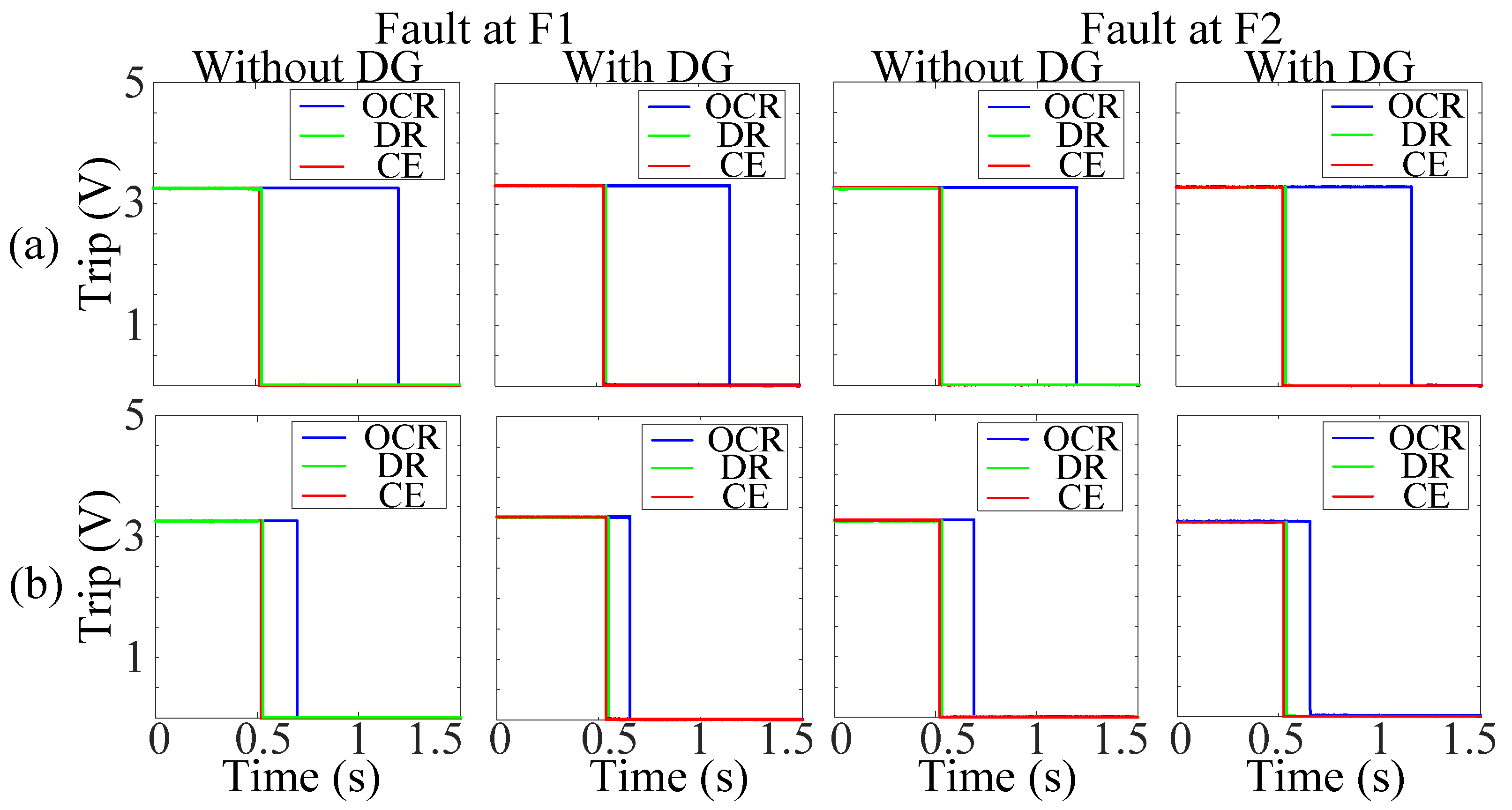
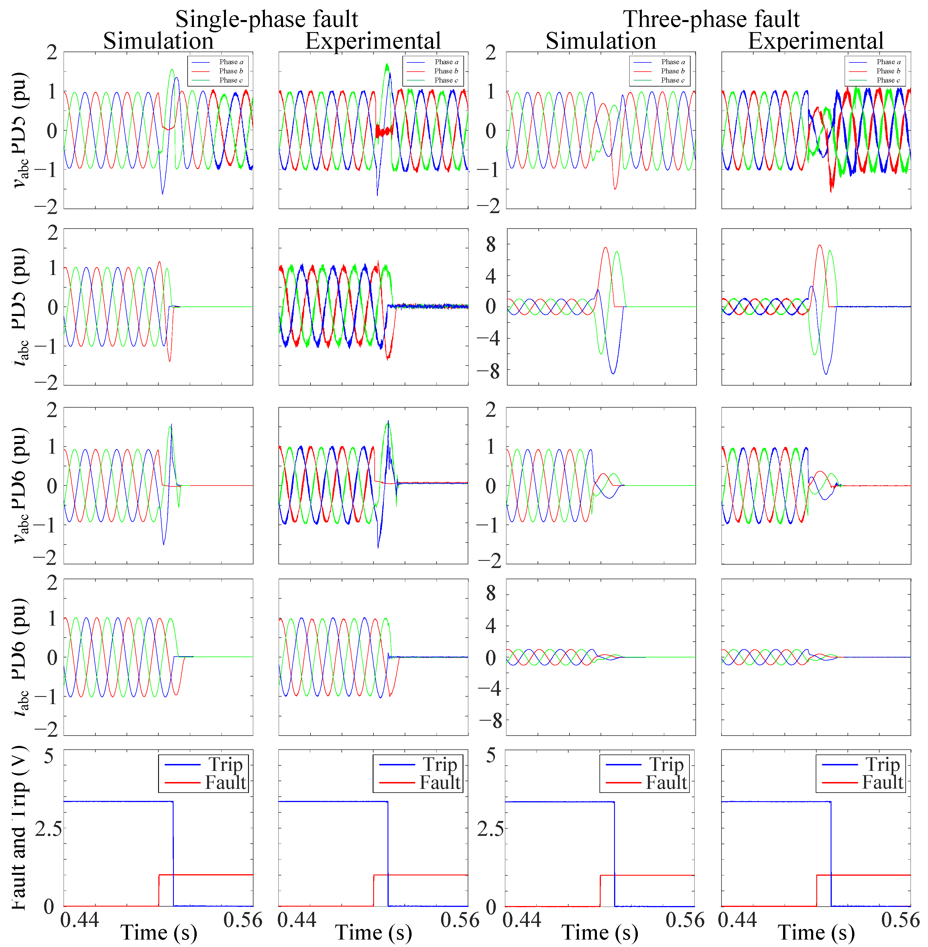
Several tests were done in the laboratory. Figure 10 presents the trip signals of OCR, DR, and CE-ZO protection strategies for symmetrical and unsymmetrical faults when the fault is located at F1 and F2, as seen in Figure 8b. The relay settings for the OCR and DR protection strategies were updated for each operation condition in the presence of DG. The trip times obtained for the reduced scale grid in Figure 10b are close to those obtained by simulation of the actual grid (see Figure 6). The CE-ZO algorithm was tested for different grid reconfigurations experimentally and using simulation. One experimental case is shown in Figure 11 to present the evolution of the abc voltages and currents for symmetrical and unsymmetrical faults with CE-ZO algorithms. It can be noticed that the simulation and experimental results are matched, and as is explained in Section 3, the CE-ZO protection strategy gives the best performance. Moreover, no relay setting updating is required.
Figure 12 shows the experimental and simulation behavior of the OCR, DR, and CE-ZO protection schemes and demonstrates the differences between them using the abc currents at both ends of the faulted line. The algorithms were tested when a three-phase fault was at F1 and F2 (see Figure 8b). The results show that the CE-ZO protection and the DR in the tested cases give a faster trip decision than OCR, as shown in the third row of Figure 12. Table 5 shows the effectiveness of the proposed strategy with other strategies operating under similar conditions. The proposed protection strategy compared to other protection strategies in terms of experimental verification, grid reconfiguration, trip time, advantages and disadvantages, is shown. It can be concluded that the proposed strategy provides fast tripping, and can deal with variable DG penetration, fault locations, fault types, (HV/MV) transformer configurations, and fault resistances. However, the disadvantage is the communication problems.
6. Conclusions
Smart grids with MGs have several configurations due to load consumption, reconfigurations due to faults or maintenance, and DG penetration dynamic changes. Therefore, renewable energies connected to smart grids require advanced protection strategies to avoid undesired tripping, and the parameters of OCR and DR protection strategies are complicated to fit and cannot be adapted to these changes in some cases. These drawbacks can only be solved through a complex updated process of the protection settings, which may not be possible when MGs are connected to smart grids. The major contribution is the comparison and the experimental validation of the proposed protection strategies with OCR and DR strategies. In addition, the drawbacks of conventional strategies are highlighted experimentally in the lab and solved with the developed AI protection. A protection strategy was developed using AI, which was used to solve the highlighted drawbacks of conventional protections and was validated experimentally to protect smart grids effectively to avoid these drawbacks. The protection scheme is based on two AI-based strategies to guarantee backup protection. The protection strategies based on a directional relay with an ANN can adapt to different grid reconfigurations. In addition, the trip decision is faster than conventional relays. The new approach improves the system’s accuracy and speeds up the response of the protection system to unexpected changes in the grid. A comparison between conventional OCR, DR, and AI CE-ZO protection strategies illustrated the effectiveness of the proposed protection strategy. Moreover, the given strategies were tested experimentally in the laboratory for several grid situations through a scaled model designed and built to emulate the analyzed MV DS. Furthermore, the trip time speed of the PD was compared with other topologies operating under similar conditions. The AI-based protection strategies showed their practical advantages over conventional protections similar to the simulation results.
Author Contributions
Conceptualization: M.B. and S.B.; Funding acquisition: A.A. and S.W.; Investigation: M.B., S.B., F.C., A.A. and J.I.; Methodology: M.B. and S.B.; Software: M.B. and S.B.; Supervision: S.B., F.C. and S.W.; Validation: M.B.; Writing—original draft preparation: M.B. and S.B.; Writing—review & editing: M.B., S.B., F.C., A.A., S.W. and J.I. All authors have read and agreed to the published version of the manuscript.
Funding
This work is supported by Li Dak Sum Innovation Fellowship Funding (E06211200006) from the University of Nottingham Ningbo China.
Informed Consent Statement
Not applicable.
Data Availability Statement
Not applicable.
Conflicts of Interest
The authors declare no conflict of interest.
References
- Ates, Y.; Uzunoglu, M.; Karakas, A.; Boynuegri, A.R. The Case Study Based Protection Analysis for Smart Distribution Grids Including Distributed Generation Units. In Proceedings of the 12th IET International Conference on Developments in Power System Protection (DPSP 2014), Copenhagen, Denmark, 31 March–3 April 2014; pp. 1–5. [Google Scholar]
- Singh, V.K.; Nath, T. Energy generation by small hydro power plant under different operating condition. Int. J. Hydromech. 2021, 4, 331–349. [Google Scholar] [CrossRef]
- Qiu, Z.; Chen, Y.; Liu, X.; Zhang, L.; Cheng, H. Evaluation and comparison of sideband harmonics and acoustic responses with continuous and discontinuous PWM strategies in permanent magnet synchronous motor for electric vehicles. Int. J. Hydromech. 2022, 5, 109–123. [Google Scholar] [CrossRef]
- Watson, J.; Schmela, M. Global Market Outlook for Solar Power; Solar Power Europe: Brussels, Belgium, 2018. [Google Scholar]
- Yu, J.J.Q.; Hou, Y.; Lam, A.Y.S.; Li, V.O.K. Intelligent Fault Detection Scheme for Microgrids with Wavelet-based Deep Neural Networks. IEEE Trans. Smart Grid 2017, 3053, 1694–1703. [Google Scholar] [CrossRef]
- P.O.12.2: Technical Requirements of Wind Power and Photovoltaic Facilities (Draft); Red Electra: Madrid, Spain, 2008.
- Perera, N.; Rajapakse, A.D.; Buchholzer, T.E. Isolation of faults in distribution networks with distributed generators. IEEE Trans. Power Deliv. 2008, 23, 2347–2355. [Google Scholar] [CrossRef]
- Yeh, C.; Chen, C.; Member, S.; Ku, T.; Lin, C.; Member, S.; Hsu, C.; Chang, Y.; Lee, Y. Design of Special Protection System for an Offshore Island With High-PV Penetration. IEEE Trans. Ind. Appl. 2017, 53, 947–953. [Google Scholar] [CrossRef]
- Momoh, J. Smart Grid: Fundamentals of Design and Analysis, 1st ed.; John Wiley & Sons: Hoboken, NJ, USA, 2012. [Google Scholar]
- Gururajapathy, S.S.; Mokhlis, H.; Illias, H.A. Fault location and detection techniques in power distribution systems with distributed generation: A review. Renew. Sustain. Energy Rev. 2017, 74, 949–958. [Google Scholar] [CrossRef]
- Lu, Y.; Member, S.; Du, J.; Member, S.; Lin, X.; Ma, J. An Asymmetrical Fault Line Selection Based on I2 Scalar Product Research in Distribution System with DGs. In Proceedings of the 2008 IEEE Power and Energy Society General Meeting—Conversion and Delivery of Electrical Energy in the 21st Century, Pittsburgh, PA, USA, 20–24 July 2008; pp. 1–6. [Google Scholar]
- Tendayi, P.; Bansal, R. Renewable distributed generation: The hidden challenges—A review from the protection perspective. Renew. Sustain. Energy Rev. 2016, 58, 1457–1465. [Google Scholar] [CrossRef]
- Senarathna, T.S.S.; Udayanga Hemapala, K.T.M. Review of adaptive protection methods for microgrids. AIMS Energy 2019, 7, 557–578. [Google Scholar] [CrossRef]
- Norshahrani, M.; Mokhlis, H.; Bakar, A.H.A.; Jamian, J.J.; Sukumar, S. Progress on protection strategies to mitigate the impact of renewable distributed generation on distribution systems. Energies 2017, 10, 1864. [Google Scholar] [CrossRef] [Green Version]
- Van Der Walt, H.L.R.; Bansal, R.C.; Naidoo, R. PV based distributed generation power system protection: A review. Reinf. Plast. 2018, 24, 33–40. [Google Scholar] [CrossRef]
- Bakkar, M.; Bogarra, S.; Córcoles, F.; Iglesias, J. Overcurrent protection based on ANNs for smart distribution networks with grid-connected VSIs. IET Gener. Transm. Distrib. 2020, 15, 1159–1174. [Google Scholar] [CrossRef]
- Hussain, N.; Nasir, M.; Vasquez, J.C.; Guerrero, J.M. Recent Developments and Challenges on AC Microgrids Fault Detection and Protection Systems—A Review. Energies 2020, 13, 2149. [Google Scholar] [CrossRef]
- Aghdam, T.S.; Kazemi Karegar, H.; Zeineldin, H.H. Variable tripping time differential protection for microgrids considering DG stability. IEEE Trans. Smart Grid 2019, 10, 2407–2415. [Google Scholar] [CrossRef]
- Mahmoudian Esfahani, M.; Mohammed, O. An intelligent protection scheme to deal with extreme fault currents in smart power systems. Int. J. Electr. Power Energy Syst. 2020, 115, 105434. [Google Scholar] [CrossRef]
- Ustun, T.S.; Khan, R.H. Multiterminal Hybrid Protection of Microgrids over Wireless Communications Network. IEEE Trans. Smart Grid 2015, 6, 2493–2500. [Google Scholar] [CrossRef]
- Nougain, V.; Mishra, S.; Pradhan, A.K. MVDC Microgrid Protection Using a Centralized Communication With a Localized Backup Scheme of Adaptive Parameters. IEEE Trans. Power Deliv. 2019, 34, 869–878. [Google Scholar] [CrossRef]
- Manohar, M.; Koley, E.; Ghosh, S. Enhancing the reliability of protection scheme for PV integrated microgrid by discriminating between array faults and symmetrical line faults using sparse auto encoder. IET Renew. Power Gener. 2019, 13, 308–317. [Google Scholar] [CrossRef]
- Yuan, C.; Member, S.; Haj-ahmed, M.A.; Member, S.; Illindala, M.S.; Member, S. Protection Strategies for Medium-Voltage Direct-Current Microgrid at a Remote Area Mine Site. IEEE Trans. Ind. Appl. 2015, 51, 2846–2853. [Google Scholar] [CrossRef]
- Adewole, A.C. Investigation of Methodologies for Fault Detection and Diagnosis in Electric Power System Protection. Master’s Thesis, Cape Peninsula University of Technology, Cape Town, South Africa, 2012. [Google Scholar]
- Yogee, G.S.; Mahela, O.P.; Kansal, K.D.; Khan, B.; Mahla, R.; Alhelou, H.H.; Siano, P. An algorithm for recognition of fault conditions in the utility grid with renewable energy penetration. Energies 2020, 13, 2383. [Google Scholar] [CrossRef]
- Pujiantara, R.F.; Pujiantara, M.; Priyadi, A.; Asfani, D.A. Protection coordination using zone selective interlocking method and neural network in IEEE 9 bus plan. In Proceedings of the 2018 International Conference on Information and Communications Technology (ICOIACT), Yogyakarta, Indonesia, 6–7 March 2018; pp. 196–201. [Google Scholar]
- He, J.; Liu, L.; Xu, Y.; Ding, F.; Zhang, D. A two-step protection algorithm for smart distribution systems with DGs. Int. Trans. Electr. Energy Syst. 2018, 28, e2506. [Google Scholar] [CrossRef]
- Baran, M.E.; Hooshyar, H.; Shen, Z.; Huang, A. Accommodating high PV penetration on distribution feeders. IEEE Trans. Smart Grid 2012, 3, 1039–1046. [Google Scholar] [CrossRef]
- Jamali, S.; Borhani-Bahabadi, H. Non-communication protection method for meshed and radial distribution networks with synchronous-based DG. Int. J. Electr. Power Energy Syst. 2017, 93, 468–478. [Google Scholar] [CrossRef]
- Kida, A.A.; Labrador Rivas, A.E.; Gallego, L.A. An improved simulated annealing–linear programming hybrid algorithm applied to the optimal coordination of directional overcurrent relays. Electr. Power Syst. Res. 2020, 181, 106197. [Google Scholar] [CrossRef]
- Shabani, A.; Mazlumi, K. Evaluation of a Communication-Assisted Overcurrent Protection Scheme for Photovoltaic-Based DC Microgrid. IEEE Trans. Smart Grid 2020, 11, 429–439. [Google Scholar] [CrossRef]
- Mirsaeidi, S.; Mat Said, D.; Wazir Mustafa, M.; Hafiz Habibuddin, M.; Ghaffari, K. An analytical literature review of the available techniques for the protection of micro-grids. Int. J. Electr. Power Energy Syst. 2014, 58, 300–306. [Google Scholar] [CrossRef]
- Han, B.; Li, H.; Wang, G.; Zeng, D.; Liang, Y. A Virtual Multi-Terminal Current Differential Protection Scheme for Distribution Networks with Inverter-Interfaced Distributed Generators. IEEE Trans. Smart Grid 2018, 9, 5418–5431. [Google Scholar] [CrossRef]
- Ghotbi-Maleki, M.; Chabanloo, R.M.; Zeineldin, H.H.; Miangafsheh, S.M.H. Design of Setting Group Based Overcurrent Protection Scheme for Active Distribution Networks Using MILP. IEEE Trans. Smart Grid 2020, 12, 1185–1193. [Google Scholar] [CrossRef]
- Sharaf, H.M.; Zeineldin, H.H.; El-Saadany, E. Protection coordination for microgrids with grid-connected and islanded capabilities using communication assisted dual setting directional overcurrent relays. IEEE Trans. Smart Grid 2018, 9, 143–151. [Google Scholar] [CrossRef]
- Alam, M.N.; Gokaraju, R.; Chakrabarti, S. Protection coordination for networked microgrids using single and dual setting overcurrent relays. IET Gener. Transm. Distrib. 2020, 14, 2818–2828. [Google Scholar] [CrossRef]
- Hong, L.; Rizwan, M.; Wasif, M.; Ahmad, S.; Zaindin, M.; Firdausi, M. User-Defined Dual Setting Directional Overcurrent Relays with Hybrid Time Current-Voltage Characteristics-Based Protection Coordination for Active Distribution Network. IEEE Access 2021, 9, 62752–62769. [Google Scholar] [CrossRef]
- Shih, M.Y.; Conde, A.; Leonowicz, Z.; Martirano, L. An Adaptive Overcurrent Coordination Scheme to Improve Relay Sensitivity and Overcome Drawbacks due to Distributed Generation in Smart Grids. IEEE Trans. Ind. Appl. 2017, 53, 5217–5228. [Google Scholar] [CrossRef] [Green Version]
- Shih, M.Y.; Conde, A.; Ángeles-Camacho, C.; Fernández, E.; Leonowicz, Z.; Lezama, F.; Chan, J. A two stage fault current limiter and directional overcurrent relay optimization for adaptive protection resetting using differential evolution multi-objective algorithm in presence of distributed generation. Electr. Power Syst. Res. 2021, 190, 106844. [Google Scholar] [CrossRef]
- Li, W.; Tan, Y.; Li, Y.; Cao, Y.; Chen, C.; Zhang, M. A New Differential Backup Protection Strategy for Smart Distribution Networks: A Fast and Reliable Approach. IEEE Access 2019, 7, 38135–38145. [Google Scholar] [CrossRef]
- Kar, S.; Samantaray, S.R.; Zadeh, M.D. Data-Mining Model Based Intelligent Differential Microgrid Protection Scheme. IEEE Syst. J. 2017, 11, 1161–1169. [Google Scholar] [CrossRef]
- Allahdadi, K.; Sadeghkhani, I.; Fani, B. Protection of Converter-Interfaced Microgrids Using Modified Short-Time Correlation Transform. IEEE Syst. J. 2020, 14, 5172–5175. [Google Scholar] [CrossRef]
- Saleh, K.; Allam, M.A.; Mehrizi-Sani, A. Protection of Inverter-Based Islanded Microgrids via Synthetic Harmonic Current Pattern Injection. IEEE Trans. Power Deliv. 2021, 36, 2434–2445. [Google Scholar] [CrossRef]
- Shih, M.Y.; Conde Enríquez, A.; Hsiao, T.Y.; Torres Treviño, L.M. Enhanced differential evolution algorithm for coordination of directional overcurrent relays. Electr. Power Syst. Res. 2017, 143, 365–375. [Google Scholar] [CrossRef]
- Mishra, P.; Kumar Pradhan, A.; Bajpai, P. Adaptive Relay Setting for Protection of Distribution System with Solar PV. In Proceedings of the 2018 20th National Power Systems Conference (NPSC), Tiruchirappalli, India, 14–16 December 2018; Volume 2, pp. 1–5. [Google Scholar] [CrossRef]
- Solak, K.; Rebizant, W.; Klimek, A. Fuzzy adaptive transmission-line differential relay immune to CT saturation. IEEE Trans. Power Deliv. 2012, 27, 766–772. [Google Scholar] [CrossRef]
- Samadi, A.; Mohammadi Chabanloo, R. Adaptive coordination of overcurrent relays in active distribution networks based on independent change of relays’ setting groups. Int. J. Electr. Power Energy Syst. 2020, 120, 106026. [Google Scholar] [CrossRef]
- Mishra, M.; Panigrahi, R.R.; Rout, P.K. A combined mathematical morphology and extreme learning machine techniques based approach to micro-grid protection. Ain Shams Eng. J. 2019, 10, 307–318. [Google Scholar] [CrossRef]
- SRZ001: Particular Technical Specifications of HV/MV Substations; Laboratorio Central Oficial de Electrotecnia: Madrid, Spain, 2018.
- Kayri, M. Predictive abilities of Bayesian regularization and levenberg-marquardt algorithms in artificial neural networks: A comparative empirical study on social data. Math. Comput. Appl. 2016, 21, 20. [Google Scholar] [CrossRef]
- IEC 61850 Communication Protocol Manual; ABB Co.: Västerås, Sweden, 2011.
- Kezunovic, M.; Ren, J.; Lotfifard, S. Design, Modeling and Evaluation of Protective Relays for Power Systems, 1st ed.; Springer: Cham, Switzerland, 2016. [Google Scholar]
- Benmouyal, G.; Meisinger, M.; Burnworth, J.; Elmore, W.A.; Freirich, K.; Kotos, P.A.; Leblanc, P.R.; Lerley, P.J.; McConnell, J.E.; Mizener, J.; et al. IEEE standard inverse-time characteristic equations for overcurrent relays. IEEE Trans. Power Deliv. 1999, 14, 868–871. [Google Scholar] [CrossRef]
Figure 1.
Single line diagram of a distribution system with DG penetration and Centralized (CE)/Zone (ZO) control topologies.
Figure 1.
Single line diagram of a distribution system with DG penetration and Centralized (CE)/Zone (ZO) control topologies.

Figure 2.
Structure of the ANN for fault location scheme.

Figure 3.
Flowchart of the ANN training procedure.

Figure 4.
Flowchart of the proposed protection scheme.

Figure 5.
Short-circuit current for OCR, DR, and CE-ZO behavior during a three-phase fault in DL3 with fault resistance r = 0.1 Ω (a) with two DGs, (b) with one DG, and (c) without DG.
Figure 5.
Short-circuit current for OCR, DR, and CE-ZO behavior during a three-phase fault in DL3 with fault resistance r = 0.1 Ω (a) with two DGs, (b) with one DG, and (c) without DG.

Figure 6.
Trip signal of OCR, DR, and CE-ZO behavior during symmetrical and unsymmetrical faults with different fault resistance (a) with two DGs, (b) with one DG, and (c) without DG.
Figure 6.
Trip signal of OCR, DR, and CE-ZO behavior during symmetrical and unsymmetrical faults with different fault resistance (a) with two DGs, (b) with one DG, and (c) without DG.

Figure 7.
Short-circuit current for DR behavior during a single-phase fault in DL3 with fault resistance r = 0.1 Ω (a) without DGs, and (b) with two DGs.
Figure 7.
Short-circuit current for DR behavior during a single-phase fault in DL3 with fault resistance r = 0.1 Ω (a) without DGs, and (b) with two DGs.

Figure 8.
The procedure of the experimental verification: (a) Proposed algorithms concept diagram; (b) analyzed grid.
Figure 8.
The procedure of the experimental verification: (a) Proposed algorithms concept diagram; (b) analyzed grid.

Figure 9.
Complete laboratory setup.

Figure 10.
Digital output of OCR, DR, and CE-ZO with DG during a (a) single-phase fault, and (b) three-phase fault.
Figure 10.
Digital output of OCR, DR, and CE-ZO with DG during a (a) single-phase fault, and (b) three-phase fault.

Figure 11.
Simulation and experimental abc voltages and currents of PD5, PD6, and trip signals of the CE-ZO algorithm decision in the case of a three-phase fault, and a single-phase at F2.
Figure 11.
Simulation and experimental abc voltages and currents of PD5, PD6, and trip signals of the CE-ZO algorithm decision in the case of a three-phase fault, and a single-phase at F2.

Figure 12.
The performance of (a) OCR, (b) DR, and (c) CE-ZO during a three-phase fault at F1.


Table 1.
Grid parameters.
| Main Grid | HV/MV Transformer (YNd11) | Zig-Zag | DL | MV/LV Transformer (Dyn11) | DG |
|---|---|---|---|---|---|
| Rated voltage: 66 kV Short circuit power: 360 MVA | Rated power: 25 MVA Rated voltage: 66/20 kV Usc (%): 11 | Grounding reactance:69.282 Ω Single-phase fault current: 500 A | Resistance: 0.16 Ω/km Reactance: 0.109 Ω/km Capacitance: 0.309 μF/km Line length: 2 km | Rated power: 3 × 2 MVA Rated voltage: 20/0.4 kV Usc (%): 4.5 | Rated power: 6 MVA Rated voltage: 400 V |
Table 2.
OCR settings.
| Parameter (OCR) | Value |
|---|---|
| Pick up current (pu) | 1 |
| Time Dial (TD) | 0.5 |
| Current Transformer (CT) | 500:1 |
Table 3.
DR settings.
| Parameter (DR) | Value |
|---|---|
| Differential current (pu) | 1.08 |
| Biased characteristic (K) | 0.5 |
| Current Transformer (CT) | 500:1 |
Table 4.
System parameters.
| Components | Parameters | Values |
|---|---|---|
| CINERGIA Inverter | Rated power | 10 kVA |
| Rated voltage | 400 V | |
| Filter | Inductance (L) | 10 mH |
| Resistance (R) | 0.2 Ω | |
| DC bus | DC rated voltage | 800 V |
| Three-phase Pacific Power Source | 345AMXT | 4.5 kVA |
| SSR | Crydom H12WD4850 | 48–660 VAC |
| Distribution Lines (LN1, LN2, LN3) | Inductance (L1, L2, L3) | 2.74, 1.37, 4.11 mH |
| Resistance (R1, R2, R3) | 1250, 625, 1875 mΩ | |
| Capacitance (C1, C2, C3) | 0.632, 0.316, 10, 30 µF | |
| Loads | Inductance (L1, L2) | 10, 30 mH |
| Resistance (R1, R2) | 14.5, 42 Ω |
Table 5.
Comparison of the proposed strategy among other topologies operating under similar conditions.
Table 5.
Comparison of the proposed strategy among other topologies operating under similar conditions.
| References | Protection Strategy | Experimental Verification | Grid Reconfiguration | Trip Time | Advantages | Disadvantages |
|---|---|---|---|---|---|---|
| [22] | DNN | Yes | No | 14 ms | Fast tripping, Variable DG penetration, Different fault resistance | Communication problems, The offline calculation, Not adaptable for network modifications |
| [27] | Multi-terminal DR | Yes | No | 90 ms | Fast tripping, variable DG penetration, different fault resistance | Communication problems |
| Proposed method [16] | CE-ZO | Yes | Yes | 10 ms | Fast tripping, variable DG penetration, fault locations, fault types, (HV/MV) transformer configuration, fault resistance. | Communication problems |
| [35] | Dual setting OCR | No | Yes | >100 ms | Variable DG penetration, high fault resistance | Offline calculation |
| [37] | OCR | No | No | >200 ms | High DG penetration, different fault resistance | Offline calculation, not adaptable for network modifications |
| [38] | MAS and OCR | No | No | 300 ms | High DG penetration, no central controller | Communication problems |
| [45] | Centralize controller and Linear programming | No | Yes | 421 ms | Variable DG penetration, no need for training, obtain relay settings simultaneously | Communication problems, knowledge of DG and PD status, more complex with large no. of buses |
Publisher’s Note: MDPI stays neutral with regard to jurisdictional claims in published maps and institutional affiliations. |
© 2022 by the authors. Licensee MDPI, Basel, Switzerland. This article is an open access article distributed under the terms and conditions of the Creative Commons Attribution (CC BY) license (https://creativecommons.org/licenses/by/4.0/).
Share and Cite
MDPI and ACS Style
Bakkar, M.; Bogarra, S.; Córcoles, F.; Aboelhassan, A.; Wang, S.; Iglesias, J. Artificial Intelligence-Based Protection for Smart Grids. Energies 2022, 15, 4933. https://0-doi-org.brum.beds.ac.uk/10.3390/en15134933
AMA Style
Bakkar M, Bogarra S, Córcoles F, Aboelhassan A, Wang S, Iglesias J. Artificial Intelligence-Based Protection for Smart Grids. Energies. 2022; 15(13):4933. https://0-doi-org.brum.beds.ac.uk/10.3390/en15134933
Chicago/Turabian StyleBakkar, Mostafa, Santiago Bogarra, Felipe Córcoles, Ahmed Aboelhassan, Shuo Wang, and Javier Iglesias. 2022. "Artificial Intelligence-Based Protection for Smart Grids" Energies 15, no. 13: 4933. https://0-doi-org.brum.beds.ac.uk/10.3390/en15134933
Note that from the first issue of 2016, this journal uses article numbers instead of page numbers. See further details here.