1. Introduction
The enameled wires used for conventional windings are insulated with polymers and their application processes require toxic solvents and high energy consumption. Advances in insulation technologies and application processes are of ecological and economic interest [
1]. Electrical machines are exposed to many stresses that contribute to the degradation of the electrical insulation systems (EIS), such as thermal stress [
2]. In this context, the design of new winding insulation systems is guided by the interest in improving the performance of electric motors, by increasing the thermal class of insulated wires, that make up their coils and reducing the environmental impact caused by the enameled wire production.
Several standards define the insulated wires for machine coils, including the conductor diameter, the thickness of the insulating layer, and the various mechanical and thermal tests of the wires [
3]. The thermal class of electrical insulators is classified by international standards [
4]. This characteristic of wire insulation defines its performance. The material with high thermal endurance can support electrical and mechanical constraints under higher temperature circumstances. This is interesting for electrical and electronic applications.
This work presents the development of extruded enameled wires based on a sequence of tests using different polymers and mineral varnish obtained by the sol-gel process on the enamel layer and different resins on the extrusion layer. The proposed wires are manufactured in a laboratory-scale enameling line present in LSEE. The new insulation structures tested are in development and offer a promising, more environmentally friendly solution for electrical insulation systems for winding wires. Their analyses are based on mechanical, thermal, and electrical test specifics for enameled wires. The resistance to the thermal aging test is the main factor of analysis to investigate the insulator material’s ability to improve the thermal index of the enameled wire.
2. Literature Basis
2.1. High-Temperature Resistant Polymer Dielectric (HTPDs)
The polymer materials that possess enough thermal endurance for high-temperature operations (above 175 °C) are called high-temperature-resistant polymer dielectrics (HTPDs) [
5]. For the HTPD used in electrical applications, the principal required characteristics are high thermal stability, high dielectric strength, and good adhesion to the copper conductor (in the case of enameled wires) [
6]. They have those favorable properties because of their high-energy chemical bonds, strong inter- and intramolecular interactions, and conjugation action along the polymer chain [
7]. The most common dielectric polymers used in electrical insulation systems for high-temperature applications are [
5,
8]
polyimide (PI) films, varnish, plastics, and tapes;
polyamide-imide (PAI) plastics and varnish;
polyetheretherketone (PEEK) film;
polyesterimide (PEI) film;
polyphenylquinoxaline (PPQ) varnish; and
polybenzimidazole (PBI) plastics.
Polymers imide enamels (PEI, PAI, PI) are used to insulate the winding wires of electrical machines. Their favorable properties for this application are high thermal and oxidative stability, high dielectric strength, and high mechanical strength [
5,
9].
The polyimide (PI) varnish undergoes a chemical reaction during the coating process called imidization. The solvents are evaporated (by the annealing process as described in
Section 3.1), and the precursor is dehydrated, resulting in the closure of the rings, and the PI coating [
6]. The thermal class of this polymer is 220 °C and can reach 240 °C for 25 µm thickness.
The polyamide-imide (PAI) combines the good properties of PI and good processability. The PAI varnish is characterized by a 220 °C thermal class and is frequently used on topcoats in electrical insulations of wires with a PEI underlay [
5,
9].
The polyesterimide (PEI) is a modified version of PI, with lower thermal stability due to its flexible ether linkage [
9]. This polymer is characterized by a 200 °C thermal class.
2.2. Sol-Gel Technology
Sol-gel is a process that allows the synthesis of materials from precursors in solution. The main application of this process is the application of thin films, which were initially used for the manufacture of low-temperature glasses. The exploitation of this process has opened space for the development of hybrid materials (nanocomposites) [
10]. Materials derived from the sol-gel method can be produced from various substances such as silica, metals, organics, cellulose, and carbon [
11].
Nanoparticles have an impact on the macrostructure that starts with the polarization generated at the atomic scale, which affects the morphologies of the material, followed by their electromagnetic interactions affecting their characteristic (complex parameter, complex permittivity, and many other dielectric parameters) [
12].
Sol-gel is an attractive method to obtain the dispersion of nanoparticles and improve the properties of the enamel wire [
13]. Interesting observations have been made on nanocomposites polymers containing different contents of silica particles obtained by the sol-gel process (from 0% to 20%) [
14]. These observations include:
The increase in thickness for the same amounts of coating applied to the wire using higher silica content. These effects were correlated with the increase of the viscosity of higher silica contents particles in the varnish compared with lower content, and neat polymer.
The glass transition temperature is also increased by the high silica content coating.
The improved surge-resistance properties if the nanoparticles are uniformly dispersed.
Previous works using the sol-gel process for coating wires have shown such good properties as breakdown voltage resistance with thin coats [
15]. These properties have also been observed after thermal degradation at high temperatures [
16]. Given these advantages, sol-gel solutions were chosen to be used in the insulation wire preparation with classical varnishes as a primer before the extrusion layer. This process is detailed in
Section 3.1 below.
2.3. Extrusion Resins
Some studies have been carried out with extruded polymers for high-voltage wire; the interest of this technology is to improve the insulation performance between turns to avoid some of the other insulators that make up the motors by reducing their weight. Some materials such as polyetheretherketone (PEEK), polyphenylene sulfide (PPS), liquid crystalline polymer (LCP), and polytetrafluoroethylene (PRFE) are crystalline resins classified as being high-temperature resistant. Those works show that the extruded thermoplastic [
17] high-temperature polymer with a base enamel insulator (PAI) had an improved performance compared with the conventional enameled wires combined with interphase paper insulators [
18].
Additives in Polymers
Different additives (particles, fibers, platelets) are used with polymers to improve the properties of the material (processability, electrical, mechanical, thermal characteristics) depending on its application. For the processability properties, the most influential factor is the homogeneous distribution of the fillers on the material. It can be a powerful source of strategic property improvement, but for large-scale exploitation, there are many obstacles such as environmental reasons, high costs, and knowledge gaps [
19].
Precedent works have shown an improvement in fracture behavior and other mechanical properties of insulations that contains mineral microfillers [
20,
21]. Part of the structure insulation of the magnet wires studied in this research activity are extruded thermoplastic resins. The presence of mineral microfillers is also tested to observe their impact on the insulation performance.
3. Materials and Methods
3.1. Conception of Insulated Wires
The process used to apply the electrical insulation to the copper wire includes the steps shown in
Figure 1. The process starts by passing the bare copper wire through a first annealing furnace at 450 °C [
22]. The temperature of this furnace is adjusted according to the wire speed. The wire is then cooled as it passes through a tank of demineralized water where its impurities are removed (the wire must be cooled quickly to avoid oxidation), and the water is blown away. During this phase, the copper is cleaned and softened, and its elasticity is improved by 40%. This step is important so that the wire can acquire the necessary flexibility to withstand the winding operations.
Next comes the varnish application phase, followed by an oven passage (curing process), where the solvents of the varnish will be evaporated, and the dry extract (the dried enamel) will remain on the wire surface. The coat application and curing process are repeated several times, to apply several layers of the enamel to the conductor. The evaporated solvents are passed through a catalyst where they are burnt and the heat from the catalyst is reused by the enamel baking oven.
Finally, the enameled wire arrives at the extruder, where a layer of resin is applied in a single pass.
The different systems for insulated wires used in this work are shown in
Figure 2.
- (i)
The enameling coatings with these primers were obtained with different varnishes in solvent (described in
Section 3.2) including PEI, PAI, PI, and composites of PAI/sol-gel solutions (sol-1 and sol-2). The thickness of the enameled layers was in the range of 20–25 µm.
- (ii)
Topcoat: thick layers obtained with extruded polymers and their composites (with fillers). The thickness of the extruded layer was in the range of 50–75 µm.
3.2. Materials Insulators
For the first part of the experiments, four types of insulating materials were applied to 0.95 mm diameter copper conductors. The temperature of the curing process used was 500 °C and the enameling speed was 20 m/min. The insulation systems consist of a primer (in solvent) applied by a classical enameling system followed by a topcoat extruded layer. The conventional polymers (used as a thick primer) used as the first coat are PEI and PAI. The solid content (dry extract) of used primers was fixed at 25%. The dilution varnishes were optimized to mainly ensure the adhesion of the extruded layer.
In a second step, the extruded coatings were applied to the primer including a pure thermoplastic polymer and the same thermoplastic polymer filled with 25% of mineral microfillers.
For
Section 4.2, the extruded polymers (and its composites) layers were kept constant (as above), and the primers were varied by adding silica sol-gel solution (sol-2) to the PAI varnish, aiming to increase the thermal class of the insulation system and studying the effect of silica (from sol-gel solution) on the performances of our systems.
To compare the new system, we used sol-gel solution-PAI as a primer, with a classical high thermal class PI varnish; the latter was used as a primer and overcoated with both extruded layers.
For the last part,
Section 4.2.1, the new primer with composites PAI-sol 1 was evaluated without extrusion layers, and the results are given for simple comparison and the work with the extruded layer needs more investigation.
The sol-gel solutions sol-1 and sol-2 were used as received, without further modifications, from Materia Nova and Esix, respectively. Both sols were obtained by hydrolysis of Si metal alkoxide precursors under acidic conditions. The solid content of the sol-1 and sol-2 were measured at 260 °C after 1 h, giving values of 40% and 12%, respectively. The sol-2 contains an adhesion promotor reacting as a plasticizer to improve its mechanical properties.
The process of using sol-gel solutions is included in a mixture of silicon sol with PAI varnish as an enamel layer. In this process, we studied two different sol-gel solutions (sol-1 and sol-2) incorporated into the PAI varnish. Both sols were obtained by hydrolysis of Si metal alkoxide precursors by using tetraethoxysilane Si-(R1O)4 and R-Si-(OR3)3), where R1 and R2 and R3 are alky groups. The mechanism of the two main reactions during hydrolysis and polymerization is presented in the equations below.
where M denotes the metal (such as Si, Ti, Zr, Al, etc.) atom and R the carbon chain (Methyl, Ethyl, etc.).
3.3. Analysis Method of Insulations Performance
After the conception of the wires, the basic properties are verified, and the thermal aging is initiated with additional dielectric measurements.
3.3.1. Characterization of the Insulated Wires
The first step is to validate whether the application of the new insulation complies with the requirements of the standards for enameled wire used in the windings of electrical machines [
3]. The property verifications are described below.
We examined the dielectric strength by measuring the breakdown voltage. The breakdown voltage measurement is made in five twisted-pair samples for each type of insulated wire. The device illustrated in
Figure 3a is following the standard IEC 60851-5 [
23]. An alternative voltage (50 Hz) is applied to the sample, starting from 0 V, and increasing until the breakdown of the sample. The speed of voltage increase is uniform and defined by the standard depending on the amplitude voltage of the breakdown expected. When the breakdown occurs, the voltage is collected, and the test is made on the other samples.
Figure 3a shows a photo of the local breakdown in a sample after the test.
Mechanical properties using tensile stress, peel tests, and flexibility are performed on three samples per insulated wire.
Figure 4 shows the flexibility and adhesion tests. Those tests are specified in the standard IEC 60851-3 [
24].
- ○
The tensile stress or snap test consists of stretching the insulated wire until it breaks. The wire is observed and if it cracks or stripped parts are visible, the wire is considered to have failed the test (KO); otherwise, the sample is considered good (Ok). This test is applied to a wire of 25 cm in length; this allows us to check the quality of adhesion insulation to the copper.
- ○
The “peel test” is used to check the adhesion of the insulation to the copper. The insulated wire of 50 cm in length is stretched under a 25 N load defined for the wires of 1 mm to 1.4 mm in diameter. The top and bottom parts of the insulation are removed. The insulated wire is rotated at a speed of 80 revolutions per minute, and the number of revolutions required to reach the loss of adhesion is counted.
- ○
Flexibility is achieved by winding the wire around its diameter until at least 10 turns are made. The sample is classified as good if there are no cracks visible under the binoculars (zoom 6×). If the sample fails this test, more tests are made in a reduced constraint whereby the wire is wrapped around a support corresponding to two times its diameter or more.
Thermal and thermomechanical properties were evaluated by a cut-through (thermoplastic flow) test. This test was carried out based on the ASTM D1676—03 standard [
25]. This test consists of measuring the temperature necessary to deform the material and allowing an electrical contact. Each sample is composed of two insulated wires crossed and in contact. Once the test is running, a temperature is applied to the point of contact between the two round wires and increased until it reaches the cut-through temperature of the round film-insulated.
The tangent delta characteristics as a function of the temperature of each wire are also collected based on the standards IEC 62631-1 [
26] and ASTM D 150—98 [
27]. The device dissipation factor measurement is composed of an oven, and the value of the dissipation factor is collected while the temperature of the oven is increasing, as presented in
Figure 5. One sample for each insulated wire is measured. Before inserting the sample into the oven, a graphite solution is applied around the wire (the specific zone of contact with the measurement device) and dried.
3.3.2. Thermal Aging Test
The thermal aging tests are executed following the international standards [
28,
29,
30,
31,
32]. The main steps of the thermal aging test are described below.
A group of 11 twisted specimens of each type of insulation is made. They are placed at insulated support inside an oven.
A temperature and a duration of exposition are chosen.
After each thermal cycle, a voltage is applied, and the amplitude is chosen following the thickness of the insulation.
The lifetime is defined when more than 50% of the samples are broken down.
3.3.3. Dielectric Parameters Monitoring during the Thermal Degradation
The dielectric parameters are collected from the 11 specimens per wire insulation type before starting the thermal aging cycle to verify the homogeneity of the specimens:
The PDIV is collected respecting the requirements of the standard IEC 60,270 [
33]. The measurement device used in the laboratory is shown in
Figure 6. The device is composed mainly of a 1 nF coupling capacitor (CD) with one output for DP measurement and another for voltage measurement. The quadrupole (CIL/V) contains a 1-µF capacitor which, with the CD, forms a voltage divider (1000/1). The results in a low-voltage signal are proportional to the high voltage applied. This signal will be used to synchronize the partial discharge detector and visualize the waveform’s quality. A preamplifier (RPAI) is used to amplify the signals of small amplitudes of partial discharges so that the phenomenon is visible during the collection of measurements. All these components are mounted in a Faraday cage as presented in
Figure 6a, to overcome external electromagnetic interference. The compact ICM allows the measurement and display of the apparent charge pulses of partial discharges on the sinusoidal signal when a voltage level is imposed, as shown in
Figure 6b. Once the test specimen is connected, a voltage is injected and increased until repetitive pulses characterizing the partial discharges appear on the ICM Compact (the PDIV).
The impedance parameters (Rp, Cp, and Tan δ) are collected by using an Agilent 4294A Precision LCR meter based on the measurements methods defined by the standards IEC 62631-1 [
26] and ASTM D 150—98 [
27]. The frequency of measurement is selected as the accuracy indication by the catalog (10 kHz—0.08% of precision). The necessary corrections (open and short circuits) are made before the measurements to obtain the most representative values of the sample.
After each thermal cycle, the measurements are remade to monitor the evolution of those parameters during the thermal degradation. The main values of the Cp, Tan δ, and PDIV parameters for the per insulated wire group of 11 samples are plotted to analyze these evolutions.
4. Results
This section presents the results of two experimental sequences. The first one is to investigate the influence of the thermoplastic polymer with mineral fillers on the extruded layer, and the second one is to observe the sol-gel solution influence on the enamel first coat insulation.
4.1. Polymers Enamelled with Thermoplastic Polymer Extrusion Layer
The four types of insulators and their results in basic property tests are described in
Table 1.
With regard to the flexibility properties, all the structure insulators presented acceptable results. The wire was stretched to 20% of its length and turned around its diameter, and no broken parts were detected. For the first test of adhesion on cooper (snap test), the insulators showed no visible difference between them. After the snap test, it is observed the ruptured part of the wire, and the insulator didn’t present any defaults.
Observing the peel test results, a higher rate of adhesion is obtained for the wires which are not filled, PAI + thermoplastic polymer and PEI + thermoplastic polymer. The presence of mineral microfillers could modify the interactions between the coats of insulation affecting the adhesion of the insulator. Previous studies show the effects of filler–matrix interactions in filled films when subjected to high constraints lead to the formation of cavities, resulting in stretchability reduced of composite films [
34]. To accurately validate this relation between the presence of fillers and the adhesion of the insulator, more tests must be executed at the microscale also to deeply understand the changes in interactions between materials.
Observing the breakdown voltage mean values presented in
Table 1, the insulator with filled resins shows lower results but is not significant if we consider the precision of measurement. The variations between samples of the same wire reach 0.45 kV, so the difference between wires cannot be observed from these tests; higher precision is needed.
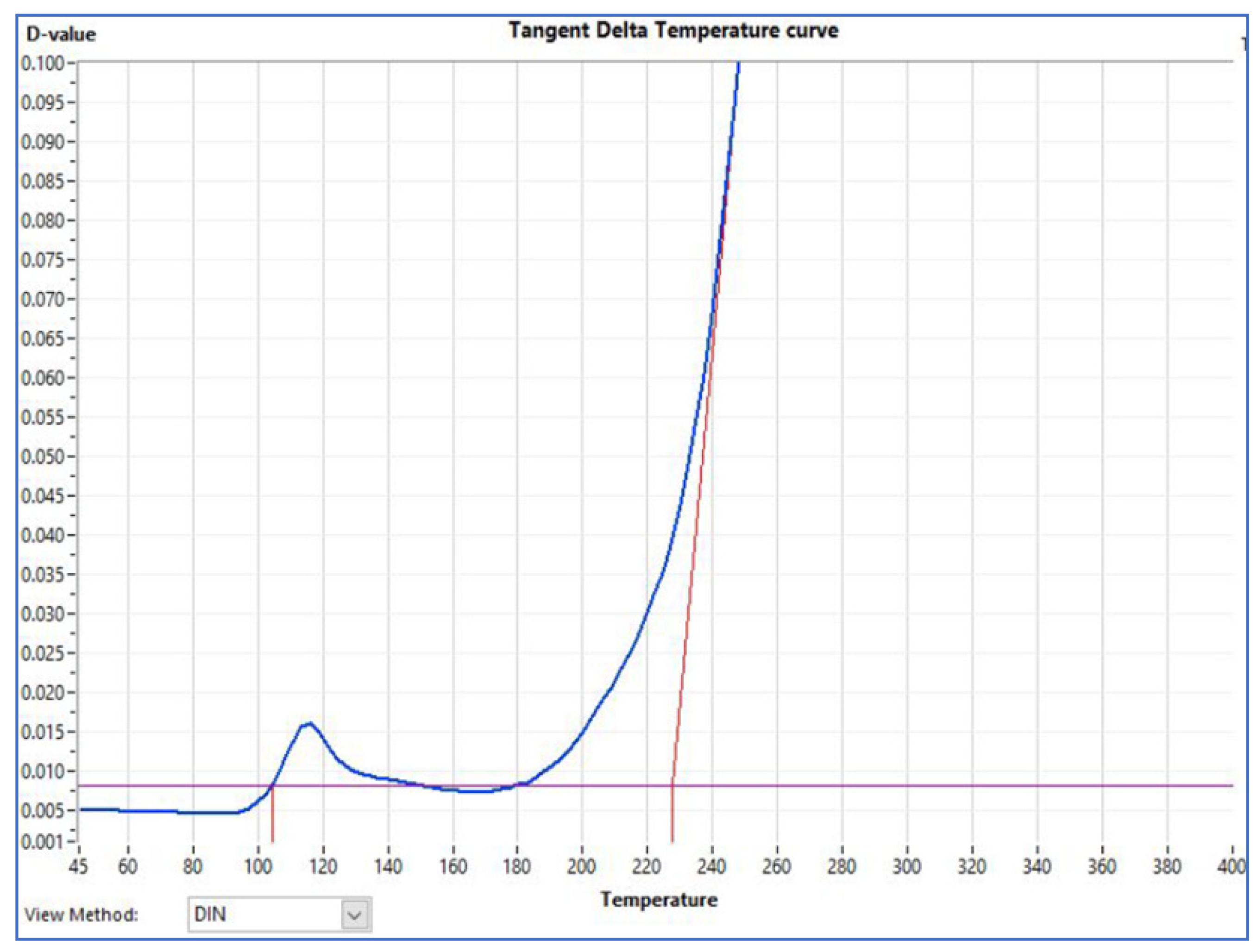
Figure 7 refers to the curve of the sample of the wire PEI + thermoplastic polymer, the tangent delta temperature behaviour obtained is the same for the four types of wires. The first pic of loss near 100 °C represents the amorphous absorption part of the topcoat thermoplastic polymer (a semi-crystalline material). The last pic represents the absorption of the primer coat when the loss factor increases exponentially. The tangent delta temperature is frequently used as an indicator of the thermal class of the insulation system wire manufacturing [
35]. The temperature values obtained don’t show a significant difference between them. Seeing these similar values of tangent delta temperature in
Table 1, a difference between the wire’s thermal class is not expected.
4.1.1. Thermal Aging Performance
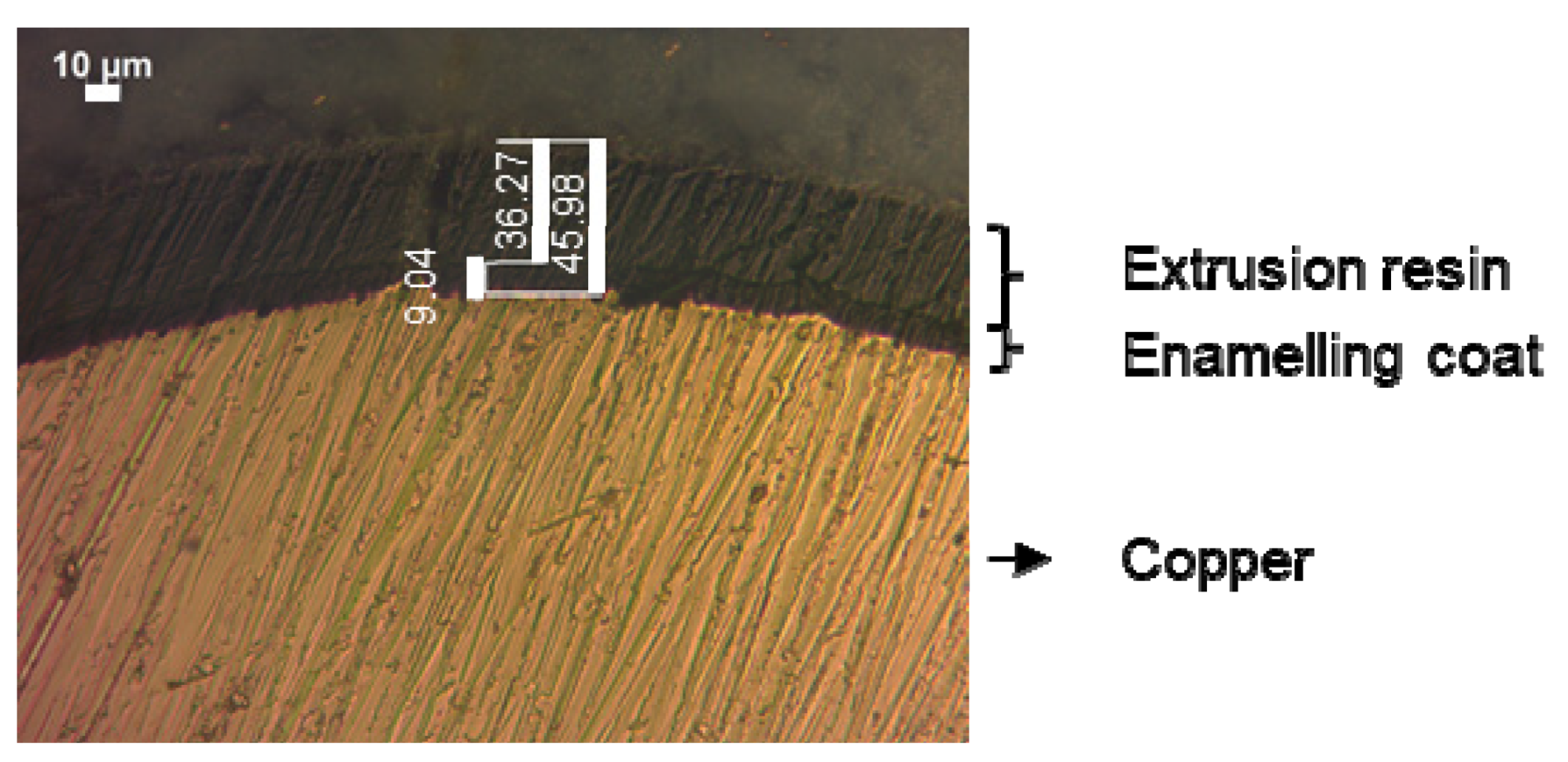
Before starting the thermal aging test, a verification of the thickness of insulation wire with an optical microscope (Carl Zeiss—AXIO, Zeiss International Germany) had been performed as shown in
Figure 8. The thickness that is shown in
Table 1, 90 μm, is referent to the insulation diameter over the copper conductor. Thickness measurements were taken on all four sides around the copper conductor, with a 50× zoom. The eccentricity is an important property of the insulated wire [
36]. The homogeneity of the insulation was checked (variations of two microns between measurements). The test voltage between cycles was chosen according to the IEC 60,172 standard [
4], which is 1000 V.
A temperature of 250 °C was chosen for the thermal aging cycles test, and it was considered that
the thermal class for each insulation material is 190 °C for the thermoplastic polymer, 220 °C for PAI, and 200 °C for PEI; and
the tangent delta curve, which presented a maximum temperature pic slightly below 250 °C.
Regarding the thermal class of the primer coats, it’s expected that the wires enameled with PAI would resist a longer period than the others. But in this experimentation, the results show in
Table 2 that the filled resin-extruded wires presented a bigger lifetime, consequently influencing a bigger thermal class. The best performing wire showed a significant difference in lifetime compared to the others.
4.1.2. Dielectric Parameters Collected between Cycles of Thermal Degradation
The dielectric parameters measured between thermal aging cycles (at constant and ambient temperature) are presented in
Figure 9.
The influence of the temperature on the parallel capacitance Cp of insulated wires needs more investigation, but in the literature [
38,
39,
40,
41] some works have been carried out and show an increased evolution of this parameter during thermal aging. The turn-to-turn capacitances collected in the samples grew up during the aging test, as expected.
For the partial discharge phenomena observed on twisted-pairs samples [
42], some works [
40,
41] show that PDIV decreases during the thermal degradation of the insulation, as the results obtained in this experience.
The parallel resistance had performed inversely with the tangent delta value. That is coherent at low frequencies when the tangent delta is affected principally by the ohmic losses.
The dielectric parameters could give some indications during the first cycles of aging, with high values of PDIV and lower values of tangent delta for the wire enameled with PAI and extruded with the filled thermoplastic resin.
After the aging tests at 250 °C, the filled thermoplastic polymer had shown an improved aspect as presented in
Figure 10. The PAI and PEI + thermoplastic polymer had shown a very damaged aspect of adhesion, which can be related to the degradation of polymers during the thermal aging caused by alterations in the molecular chains.
4.2. Polymers with a Sol-Gel Solution in Enameled Coat under Thermoplastic Polymer Extruded Layer
To explore the varnish made from the sol-gel process as a primer coat under a thermoplastic extrusion resin, the structure insulations had been made as illustrated in
Figure 2,
Section 3.1. Preliminary tests have been performed with enameled insulated wires before selecting the structures to be analyzed under the extrusion layer.
4.2.1. Preliminary Analysis of Different Enameling Structures and Sol-1 Concentrations
The term “sol-1” is used to represent one of the varnish solutions made from the sol-gel process described in
Section 3.2.
Table 3 shows the different wire insulations tested at 330 °C and the lifetime (h) obtained. The parameters of change between them are
The four types of wires have 0.5 mm in diameter and are manufactured under the same conditions of the enameling process, presented in
Table 3.
Observing the results presented, we can note that the following.
The structure insulation (b) with a pure polymer (PAI) in primer, presents a lightly lower breakdown voltage than structure (a). The insulation without PAI in primer present a higher content of sol-1; this may contribute to this property as shown in the literature in
Section 2.2. Otherwise, the wires characterized by structure (b) present higher tangent delta temperatures.
The higher concentration of the varnish made from the sol-gel process for the wires PAI + PAI (50%)/ssol-1 (50%) and PAI (50%)/sol-1 (50%), can contribute to the thermal aging resistance as shown by their long lifetime.
The higher concentration of PAI shows higher cut-through performance.
All configurations containing the sol-1 had bad results in the flexibility tests. The absence of breaks could be seen when the constraint was reduced. Instead of one diameter, the samples only could resist when they were turned around at support of 3, 4, or 5 times the diameter size.
4.2.2. Enameled Wires Using Sol-2, PAI, and Extruded Layer
Other types of varnish made from the sol-gel process have been tested in lower concentrations to minimize the degradation of the mechanical properties of the insulation. In
Table 4, we can see the different structures with the “sol-2” (the second varnish solution made from the sol-gel process as described in
Section 3.2). The factors to be observed are the structure of insulation (a) and (b), the presence of fillers on resin extrusion, and the PI enamel coat in comparison with the PAI/sol-2 for the enamel extruded layer. Observing the wires composed with the insulation presented in the three first columns, we find the following.
The snap test results, peel test, flexibility, and dielectric strength, show a low performance for the wire PAI/sol-2 + thermoplastic polymer which is composed of a structure (a). In this experience, this structure shows less performant mechanical properties (adhesion and flexibility) which could affect the breakdown voltage of the insulator.
Comparing the wires which are composed of a polymer on the interface with the cooper conductor and PPS on the extrusion layer, we find the following.
The PI + Thermoplastic polymer is characterized by a lower breakdown voltage but has good mechanical properties.
The PAI + PAI/sol-2 + filled thermoplastic polymer shows a lower performance on the peel test compared with the same non-filled insulated structure. Otherwise, the PAI +PAI/sol-2 + thermoplastic polymer without fillers has a slightly lower temperature of the tangent delta.
The tangent delta temperatures don’t show an important difference between the wires.
The less performant wire on these characterizations is PAI/sol-2 + thermoplastic polymer, which means that the polymer in primer can be a factor in the contribution of the performance insulation for the extruded enameled wires.
4.2.3. Thermal Aging Performance
The temperatures of the tangent delta are around 260 °C for the majority part of those wires; the chosen temperature of the test is 300 °C. A group of samples of the wire PAI + filled thermoplastic polymer which presented a longer lifetime on the precedent aging test had been included in this test, in addition to the wires presented in the first columns of
Table 4. The lifetime obtained is shown in
Table 5.
The short lifetime obtained by the wire PAI/sol-2 + thermoplastic polymer is coherent with its lower performance on the mechanical tests. No difference between filled and non-filled resins had been noted in this aging test result.
The sol-gel solution-PAI structure presented longer lifetimes than the PAI + filled thermoplastic polymer, which means that
the varnish made from the sol-gel process in the enamel insulator may strengthen the lifetime insulation and consequently the thermal class. It’s a possibility of insulation having less polymer, and better performance compared with entire polymer insulation. The mineral part generated by sol-2 in the PAI enamel leads to an increase in wear and thermal resistance during the aging tests. These observations agree with the literature.
4.2.4. Dielectric Parameters Collect between Cycles of Thermal Degradation
Observing the dielectric parameters between cycles (at constant and ambient temperature) during the thermal aging tests for the wires which resist longer time the thermal aging test (
Figure 11). The following can be noted.
The evolution of the parallel capacitance is increasing as the previews experience analysis. The difference between wires is not very significant.
The PDIV has an increasing evolution for all groups of samples. The PI+ thermoplastic polymer extruded layer has a bigger augmentation after the first cycle, which can be explained by a resumption of polymerization if it was not finished during the enamel process. This phenomenon is also shown in the PDIV curves of
Figure 9 referent of the 250 °C thermal aging.
The tangent delta values don’t show any different behavior that can be related to the end of life. This parameter variates inversely to parallel resistance as in the preceding experiment.
The evolution parameters are similar for the wires PAI + PAI/sol-2 + filled thermoplastic polymer and PAI + PAI/sol 2 + thermoplastic polymer, which contains the same material of enamel. That may indicate the parameters are more influenced by the interface of contact cooper and enamel, rather than extrusion topcoats.
The fillers on the extrusion layer didn’t show any impact on this aging test as the precedent test.
5. Discussion
The first part of the experimentation which analyses the extrusion layer with thermoplastic polymers and mineral fillers had been in coherence with the literature consulted. Two references showed improvement in mechanical properties:
The presence of 25% of mineral fillers showed an increase in crystallinity of the material in ref. [
21] and, it had been used as a solution to improve the toughness of the polymer in ref. [
20].
The microfillers affected the lifetime of extruded resins without affecting their tangent delta temperatures. The tangent delta temperature is not enough to predict a performance aging test for extruded enameled wires with the presence of mineral microfillers.
Concerning the lifetimes obtained by the thermal aging test, the extruded wires’ lifetimes exceed the commercial ones, which have a thermal index of 210 °C. Commercial wires enameled with PEI and PAI coat had also aged at 250 °C as shown by previous studies [
43]. The lifetime obtained for these commercial wires was 252 h, inferior to the lifetimes obtained for all the enameled extruded wires in this work.
The dielectric parameters could give some indications about the performance of the wires. In the first cycles of aging degradation, high values of PDIV and lower values of the tangent delta are collected for samples of PAI + filled thermoplastic polymer insulated wire.
In the second Section of experimentation
Section 4.2, it could be observed the good performance of the insulations with a bigger concentration of varnish made from the sol-gel process, (except in terms of mechanical properties for non-extruded wires). This can be correlated with the good dispersion of silica for the sol-1 (to be confirmed with the supply varnish). This influence is not noted for the followed tests with the sol-2 which presented better performance when composed by a PAI in primer.
For the extruded insulations, after one cycle of thermal aging, the augmentation of PDIV could be observed, which indicates some changes in the material, and possible finalization of polymerization. This hypothesis can be confirmed by deeper material analysis as a differential scanning calorimetry analysis. That means the curing process must be eventually optimized to improve the conditions of polymerization during the varnish application process.
For both experimentations, the following could be observed.
The coherence of the literature and the variation of parallel capacitance and PDIV during the aging test.
The measurements of parallel resistance presented an inverse evolution of tangent delta (tan δ) This is very close to the sample measurement model represented by a capacitor in parallel with a resistance possessing the following Equation,
where,
ω = the angular frequency (rad/s),
Cp = parallel capacity (C), and
Rp = parallel resistance (Ω).
During thermal aging at temperatures above 200 °C, copper can suffer from oxidation. This phenomenon causes overheating in the area where it occurs, the excessive heating causes oxidation to increase at a faster rate. It is known that lifetime is strongly impacted by oxidation [
44]. Complementary analyses on wires after aging must be done to deeper understand how the results obtained by the thermal aging could be influenced by copper oxidation.
6. Conclusions
In this work, we have demonstrated a great interest in the use of a new process combining classical varnishes, sol-gel solutions and free solvent topcoat using extruded polymers. We have studied three different systems of insulated wires and new processing. The samples were prepared and characterized, and the full results were discussed.
The observation of the dielectric parameters during thermal aging can give a preview of the performance of the wires. These parameters can help to make decisions for the conception of wires before the end of the aging test.
The improved performance during the thermal aging degradation is evident for the enameled wire, which presents higher contents of the silica sol (sol-1). This demonstrated that this technology can be a strategic source of improvement for HTTD insulators, although the flexibility needs to be improved. For this purpose, we believe that the extrusion part as top layers could be an appropriate solution for the complete system.
The mineral microfillers show an evident improvement for the extruded thermoplastic polymer resin during thermal aging, but can have a similar performance to a non-filled resin depending on the enamel coat underneath. A deeper analysis at the molecular scale may answer the reasons for this different behavior and explain the interaction between the top extruded and the underneath coat.
The wires are made in a laboratory, and better process conditions can be studied to exploit the technologies of the sol-gel process for the enamel layer and extrusion resin in the topcoat. The combination of enamel produced by the sol-gel process using silica sol and the extruded thermoplastic polymer is a promising option for the development of eco-friendly magnet wires. The enameled extruded wires developed and studied in this work demonstrated an improved thermal aging resistance compared to conventional enameled ones.
More investigations are being made to analyze the copper oxidation impacts during the thermal aging tests, and to choose materials that can reduce this effect.
Author Contributions
Writing—original draft preparation, G.P.d.S.L.; experimental measurements G.P.d.S.L.; results analysis, G.P.d.S.L., S.A.-A. and G.V.; mechanic characterization test wires participation, G.P.d.S.L. and P.F.; manufacturing of wires, P.F.; writing and development of the sol-gels solutions used in this study, A.B.; development of the sol-gels solutions used in this study, M.P., A.N. and P.-Y.H. All authors have read and agreed to the published version of the manuscript.
Funding
This research was funding by the INTERREG North-West Europe—European Regional Development Fund ERDF-FEDER: NWE1052 in the context of the project HI-ECOWIRE.
Institutional Review Board Statement
Not applicable.
Informed Consent Statement
Not applicable.
Data Availability Statement
The data are not publicly available due to privacy considerations.
Acknowledgments
This research work is financed by the Interreg Hi-ecowire project. The authors express thanks for the technical and human support provided by Artois University and the partners of the project HI-ECOWIRE. The authors also thank Yanis Ramboud for his contribution to manufacturing the wires studied and the partners of the Hi-ecowire for allowing the publication of this paper.
Conflicts of Interest
The authors declare no conflict of interest.
References
- INTERREG North-West Europe. HI-ECOWIRE High Quality Ecoefficient Magnet Wire. Available online: https://www.nweurope.eu/projects/project-search/hi-ecowire-high-quality-ecoefficient-magnet-wire/ (accessed on 13 May 2022).
- Höpner, V.N.; Wilhelm, V.E. Insulation Life Span of Low-Voltage Electric Motors—A Survey. Energies 2021, 14, 1738. [Google Scholar] [CrossRef]
- IEC 60317-0-1; Specifications for Particular Types of Winding Wires—Part 0-1: General Requirements—Enameled Round Copper Wire. IEC: Geneva, Switzerland, 2013.
- IEC 60172; Test Procedure for the Determination of the Temperature Index of Enameled and Tape Wrapped Winding Wires. IEC: Geneva, Switzerland, 2015.
- Zhang, X.-M.; Liu, J.-G.; Yang, S.-Y. A Review on Recent Progress of R&D for High-Temperature Resistant Polymer Dielectrics and Their Applications in Electrical and Electronic Insulation. Rev. Adv. Mater. Sci. 2016, 46, 22–38. [Google Scholar]
- Sezer Hicyilmaz, A.; Celik Bedeloglu, A. Applications of Polyimide Coatings: A Review. SN Appl. Sci. 2021, 3, 22. [Google Scholar] [CrossRef]
- Hergenrother, P.M. Perspectives in the Development of High-Temperature Polymers. Angenw. Chem. Int. Ed. 1990, 29, 1262–1268. [Google Scholar] [CrossRef]
- Stone, G.C.; Culbert, I.; Boulter, E.A.; Dhirani, H. Electrical Insulation for Rotating Machines—Design, Evaluation, Aging, Testing, and Repair; John Wiley & Sons: Hoboken, NJ, USA; IEEE Press: Piscataway, NJ, USA, 2014. [Google Scholar]
- Li, Q.; Fang-Zhou, Y.; Yang, L.; Guangzu, Z.; Hong, W.; Qing, W. High-Temperature Dielectric Materials for Electrical Energy Storage. Annu. Rev. Mater. Res. 2018, 48, 219–243. [Google Scholar] [CrossRef]
- RESCOLL Centre Technologique. Dossier Technique: Le Procédé Sol-Gel; RESCOLL: Pessac, France, 2009; Available online: https://rescoll.fr/wp-content/uploads/2009/04/dossier-technique-sol-gel-blog-rescoll1.x38096.pdf (accessed on 3 October 2021).
- Dervin, S.; Suresh, C.P.; Sarah, H. Advances in Sol-Gel Derived Materials and Technologies. In An Introduction to Sol-Gel Processing for Aerogels; Springer: Sligo, Ireland, 2017; pp. 1–22. ISBN 978-3-319-50144-4. [Google Scholar]
- Wang, Y.; Zhou, Z.; Chen, M.; Huang, Y.; Wang, C.; Song, W.-L. From Nanoscale to Macroscale: Engineering Biomass Derivatives with Nitrogen Doping for Tailoring Dielectric Properties and Electromagnetic Absorption. Appl. Surf. Sci. 2018, 439, 176–185. [Google Scholar] [CrossRef]
- Boudiba, H. INTERREG: Hi-Ecowire. Sol-Gel Process: An Outstanding Technology for Coatings. Available online: https://www.nweurope.eu/media/13370/hi_ecowire_technical_sheet_solgel_process.pdf (accessed on 16 May 2022).
- Yoo, J.; Kim, Y.; Kwon, S.; Lee, J.; Seo, Y.-S. Surge-Resistant Nanocomposite Enameled Wire Using Silica Nanoparticles with Binary Chemical Compositions on the Surface. J. Nanomater. 2015, 2015, 231672. [Google Scholar] [CrossRef]
- Pfeifer, S.; Gutierrez, A.; Kroke, E. An S-Triazine Briged Silylalkyl Sol–Gel Precursor—Synthesis, Structure and Coating Formation for Electrical Insulation of Copper Wire and Corrosion Protection of Construction Steel. Polym. Adv. Technol. 2014, 25, 1356–1365. [Google Scholar] [CrossRef]
- Morikawa, A.; Suzuki, K.; Asano, K. Enameled Wire Having Polyimide-Silica Hybrid Insulation Layer Prepared by Sol-Gel Process. J. Photopolym. Sci. Technol. 2015, 28, 151–155. [Google Scholar] [CrossRef] [Green Version]
- Schouw, T. INTERREG: Hi-Ecowire. Technical Sheet on Polymer Extrusion for Magnet Wire. Available online: https://www.nweurope.eu/media/13371/hi-ecowire_technical_sheet_polymer_extrusion.pdf (accessed on 16 May 2022).
- Ito, K.; Shibata, T.; Kawasaki, T. Development of High Voltage Wire for New Structure Motor in Full Hybrid Vehicle. SAE Int. J. Altern. Powertrains 2016, 5, 272–277. [Google Scholar] [CrossRef]
- Gressler, S.; Prenner, S.; Kurz, A.; Resch, S.; Pavlicek, A.; Part, F. Polymer Nanocomposites—Additives, Properties, Applications, Environmental Aspects; NanoTrust Dossier; Austrian Academy of Sciences: Vienna, Austria, 2020. [Google Scholar]
- Wang, K.; Wu, J.; Zeng, H. Microstructure and Fracture Behavior of Polypropylene/Barium Sulfate Composites. J. Appl. Polym. Sci. 2006, 99, 1207–1213. [Google Scholar] [CrossRef]
- Amestoy, H.; Diego, P.; Meaurio, E.; Muñoz, J.; Sarasua, J.-R. Crystallization Behavior and Mechanical Properties of Poly(ε-Caprolactone) Reinforced with Barium Sulfate Submicron Particles. Materials 2021, 14, 2368. [Google Scholar] [CrossRef] [PubMed]
- Anton, A. Émaux isolants et fils émaillés. J. Tech. L’ingénieur Convers. L’énergie Électrique 2009, 1, d2330. Available online: https://www.techniques-ingenieur.fr/base-documentaire/energies-th4/materiaux-isolants-en-electrotechnique-42255210/emaux-isolants-et-fils-emailles-d2330/proprietes-des-emaux-isolants-d2330niv10001.html (accessed on 13 May 2022). [CrossRef]
- IEC 60851-5; Winding Wires—Test Methods—Part 5: Electrical Properties. IEC: Geneva, Switzerland, 2008.
- IEC 60851-3; Winding Wires—Test Methods—Part 3: Mechanical Properties. IEC: Geneva, Switzerland, 1998.
- IEC 62631-1; Dielectric and Resistive Properties of Solid Insulating Materials. IEC: Geneva, Switzerland, 2011.
- ASTM D1676-03; Standard Test Methods for Film-Insulated Magnet Wire. ASTM: West Conshohocken, PA, USA, 2011.
- ASTM D150-98; Standard Test Methods for AC Loss Characteristics and Permittivity (Dielectric Constant) of Solid Electrical Insulation. ASTM: West Conshohocken, PA, USA, 1998.
- IEC 60216-3; Electrical Insulating Materials—Thermal Endurance Properties—Part 3: Instructions for Calculating Thermal Endurance Characteristics. IEC: Geneva, Switzerland, 2021.
- IEC 60034-18-21; Rotating Electrical Machines—Part 18–21: Functional Evaluation of Insulation Systems—Test Procedures for Wire-Wound Windings—Thermal Evaluation and Classification. IEC: Geneva, Switzerland, 2013.
- IEC 60216-1; Electrical Insulating Materials—Thermal Endurance Properties—Part 1: Ageing Procedures and Evaluation of Test Results. IEC: Geneva, Switzerland, 2013.
- IEC 60505; Evaluation and Qualification of Electrical Insulation Systems. IEC: Geneva, Switzerland, 2011.
- IEC 60270; High-Voltage Test Techniques—Partial Discharge Measurements. IEC: Geneva, Switzerland, 2000.
- DSE Test Solutions A/S. Tangent Delta Temperature Curves; DSE Test Solution: Horsens, Denmark, 2016. [Google Scholar]
- Defebvin, J.; Barrau, S.; Lyskawa, J.; Woisel, P.; Lefebvre, J.-M. Influence of nitrodopamine-functionalized barium titanate content on the piezoelectric response of poly(vinylidene fluoride) based polymer-ceramic composites. Compos. Sci. Technol. 2017, 147, 16–21. [Google Scholar] [CrossRef]
- Korcak, L.L.; Kavanagh, D.F. Thermal Accelerated Aging Methods for Magnet Wire: A Review. In Proceedings of the 2018 International Conference on Diagnostics in Electrical Engineering (Diagnostika), Pilsen, Czech Republic, 4–7 September 2018; pp. 1–4. [Google Scholar]
- Ait-Amar, S.; Koita, A.; Vélu, G. Interpretation of Eccentricity of an Enameled Wire by Capacitance Measurements. Energies 2022, 15, 2802. [Google Scholar] [CrossRef]
- Diaham, S.; Locatelli, M.L.; Lebey, T.; Dinculescu, S. Dielectric and thermal properties of Polyamide-imide (PAI) films. In Proceedings of the 2009 Annual Report Conference on Electrical Insulation and Dielectric Phenomena, Virginia Beach, VA, USA, 18–21 October 2009; pp. 482–485. [Google Scholar]
- Werynski, P.; Roger, D.; Corton, R.; Brudny, J.F. Proposition of a New Method for In-Service Monitoring of the Aging of Stator Winding Insulation in AC Motors. IEEE Trans. Energy Convers. 2006, 21, 673–681. [Google Scholar] [CrossRef]
- Savin, S.; Ait-Amar, S.; Roger, D.; Vélu, G. Aging Effects on the AC Motor Windings: A Correlation between the Variation of Turn-to-Turn Capacitance and the PDIV. In Proceedings of the 2011 Annual Report Conference on Electrical Insulation and Dielectric Phenomena, Cancun, Mexico, 6–19 October 2011; pp. 64–67. [Google Scholar]
- Savin, S.; Ait-Amar, S.; Roger, D. Turn-to-Turn Capacitance Variations Correlated to PDIV for AC Motors Monitoring. IEEE Trans. Dielectr. Electr. Insul. 2013, 20, 34–41. [Google Scholar] [CrossRef]
- Sili, E.; Cambronne, J.P. About the validity of lifetime models of polymers under electrical discharge in aeronautical environment. In Proceedings of the 2013 Annual Report Conference on Electrical Insulation and Dielectric Phenomena, Chenzhen, China, 20–23 October 2013; pp. 1306–1309. [Google Scholar]
- Florkowski, M.; Florkowska, B.; Zydron, P. Partial Discharges in Insulating Systems of Low Voltage Electric Motors Fed by Power Electronics—Twisted-Pair Samples Evaluation. Energies 2019, 12, 768. [Google Scholar] [CrossRef] [Green Version]
- Lima, G.P.d.S.; Ait-Amar, S.; Vélu, G. Study of new ecological magnet wires performances during thermal aging test. In Proceedings of the IEEE International Conference on Dielectrics, Palermo, Italy, 3–7 July 2022. [Google Scholar]
- Thomas, J.H.; Dexter, J.F. Effect of Wire Metal on the Thermal Life of Enameled Magnet Wire. IEEE Trans. Am. Inst. Electr. Eng. Part III Power Appar. Syst. 1957, 76, 1009–1013. [Google Scholar] [CrossRef]
Figure 1.
Insulation layer application process.
Figure 1.
Insulation layer application process.
Figure 2.
Wire insulation structures. (a) Enameled layer structure of composites of PAI/sol-gel solutions. (b) Enameled layer structure composed of a polymer primer and second layer composites of PAI/sol-gel solutions. (c) The global structure, enamel, and extrusion coat.
Figure 2.
Wire insulation structures. (a) Enameled layer structure of composites of PAI/sol-gel solutions. (b) Enameled layer structure composed of a polymer primer and second layer composites of PAI/sol-gel solutions. (c) The global structure, enamel, and extrusion coat.
Figure 3.
(a) Breakdown voltage device and (b) sample broken down.
Figure 3.
(a) Breakdown voltage device and (b) sample broken down.
Figure 4.
Mechanical tests. (a) Flexibility tests samples. (b) Peel test device.
Figure 4.
Mechanical tests. (a) Flexibility tests samples. (b) Peel test device.
Figure 5.
Dissipation factor measurement device: (a) Display of collected data; (b) Circulating air oven and, (c) sample with a graphite coat.
Figure 5.
Dissipation factor measurement device: (a) Display of collected data; (b) Circulating air oven and, (c) sample with a graphite coat.
Figure 6.
PDIV device. (a) Faraday cage. (b) ICM compact with the voltage control box.
Figure 6.
PDIV device. (a) Faraday cage. (b) ICM compact with the voltage control box.
Figure 7.
Tangent delta behavior for the wires PEI + thermoplastic polymer.
Figure 7.
Tangent delta behavior for the wires PEI + thermoplastic polymer.
Figure 8.
Microscopic view of insulated wire (dimensions in µm).
Figure 8.
Microscopic view of insulated wire (dimensions in µm).
Figure 9.
Mean values of dielectric parameters collected during the thermal aging test at 250 °C. (a) Parallel capacitance (Cp). (b) Partial discharge inception voltage (PDIV). (c) Dielectric loss factor (tangent delta). (d) Parallel resistance (Rp).
Figure 9.
Mean values of dielectric parameters collected during the thermal aging test at 250 °C. (a) Parallel capacitance (Cp). (b) Partial discharge inception voltage (PDIV). (c) Dielectric loss factor (tangent delta). (d) Parallel resistance (Rp).
Figure 10.
Improved aspect of filled thermoplastic polymer extruded layer after aging test at 250 °C.
Figure 10.
Improved aspect of filled thermoplastic polymer extruded layer after aging test at 250 °C.
Figure 11.
Mean values of dielectric parameters collected during the thermal aging test at 300 °C: (a) Parallel capacitance (Cp). (b) Partial discharge inception voltage (PDIV). (c) Dielectric loss factor (tangent delta). (d) Parallel resistance (Rp).
Figure 11.
Mean values of dielectric parameters collected during the thermal aging test at 300 °C: (a) Parallel capacitance (Cp). (b) Partial discharge inception voltage (PDIV). (c) Dielectric loss factor (tangent delta). (d) Parallel resistance (Rp).
Table 1.
Basics characterizations of polymers enameled with thermoplastic on extrusion layer.
Table 1.
Basics characterizations of polymers enameled with thermoplastic on extrusion layer.
| Samples | PAI + Thermoplastic
Polymer | PAI + Filled Thermoplastic Polymer | PEI + Thermoplastic
Polymer | PEI + Filled Thermoplastic Polymer |
|---|
| Enamel primer coat | PAI | PAI | PEI | PEI |
| Extrusion topcoat | Thermoplastic polymer | Thermoplastic polymer with 25% of mineral micro fillers | Thermoplastic polymer | Thermoplastic polymer with 25% of mineral micro fillers |
| Enamel/extrusion (µm) diameter over conductor | 20/70 | 20/70 | 20/70 | 20/70 |
| Snap test | OK | OK | OK | OK |
| Peel test | >240 | 200 | >240 | 220 |
| Flexibility 1D pre-stretch 20% length | OK | OK | OK | OK |
| ∑ Breakdown voltage (kV) | 7 | 7 | 6.8 | 6.1 |
| Cut through (thermoplastic flow) (°C) | >350 | >350 | >350 | >350 |
Tangent delta
temperatures (°C) | 101/240 | 103/241 | 104/227 | 101/246 |
Table 2.
Lifetime at 250 °C aging test.
Table 2.
Lifetime at 250 °C aging test.
| Samples | PAI +
Thermoplastic Polymer | PAI + Filled
Thermoplastic Polymer | PEI +
Thermoplastic Polymer | PEI + Filled
Thermoplastic Polymer |
|---|
| Lifetime (h) | 420 | 708 | 348 | 492 |
Table 3.
Characterization tests of enameled wires using Sol-1.
Table 3.
Characterization tests of enameled wires using Sol-1.
| Samples | PAI + PAI (80%)/Sol-1 (20%) | PAI + PAI (50%)/Sol-1 (50%) | PAI (50%)/Sol-1 (50%) | PAI (80%)/Sol-1 (20%) |
|---|
| Structure insulation | (b) | (b) | (a) | (a) |
| Primer polymer | PAI | PAI | - | - |
| Concentration (%) | PAI—80%/sol-1—20% | PAI—50%/sol-1—50% | PAI—50%/sol-1—50% | PAI—80%/sol-1—20% |
| Thickness layers diameter over conductor (µm) | 5 µm/40 µm | 5 µm/40 µm | 45 µm | 45 µm |
| Flexibility | 4D | 5D | 3D | 5D |
| ∑ Breakdown voltage (kV) | 7.3 | 7.6 | 9.6 | 7.9 |
| Cut through (thermoplastic flow) (°C) | 500 | 480 | 470 | >520 |
Tangent delta
temperatures (°C) | 283 | 297 | 272 | 274 |
| Lifetime (h) thermal aging at 330 °C | 12 | 60 | 60 | 12 |
Table 4.
Basics characterizations of polymers with a varnish produced by a sol-gel process on the enameled layer with a thermoplastic polymer extrusion layer.
Table 4.
Basics characterizations of polymers with a varnish produced by a sol-gel process on the enameled layer with a thermoplastic polymer extrusion layer.
| Samples | PAI +PAI/Sol-2 +
Thermoplastic Polymer | PAI + PAI/Sol-2 + Filled Thermoplastic Polymer | PAI/Sol-2 + Thermoplastic Polymer | PI + Thermoplastic Polymer |
|---|
| Structure insulation enamel | (b) | (b) | (a) | - |
| Enamel primer coat | PAI | PAI | PAI/sol-2 (18%)/PAI (82%) | PI |
| Enamel intermediary coat | PAI/sol-2 (18%)/PAI (82%) | PAI/sol-2 (18%)/PAI (82%) | - | - |
| Extrusion topcoat | Thermoplastic polymer | Filled thermoplastic polymer | PPS | PPS |
| Thickness layers over a conductor (µm) | 5/20/55 | 5/20/55 | 25/75 | 25/75 |
| Snap test | OK | OK | KO | OK |
| Peel test | 180 | 60 | KO (>60) | 120 |
| Flexibility 1D | OK at 20% elongation | OK at 20% elongation | KO | OK at 20% elongation |
| ∑ Breakdown voltage (kV) | 11.4 | 10.1 | 7.3 | 5.9 |
Tangent delta
temperatures (°C) | 105/248 | 110/260 | 100/259 | 102/260 |
Table 5.
Lifetime at 300 °C aging test.
Table 5.
Lifetime at 300 °C aging test.
| Samples | PAI + PAI/Sol-2 + Thermoplastic Polymer | PAI + PAI/Sol-2 + Filled
Thermoplastic Polymer | PAI/Sol-2 + Thermoplastic Polymer | PI +
Thermoplastic Polymer | PAI + Filled Thermoplastic Polymer |
|---|
| Lifetime at 300 °C (h) | 168 | 168 | 24 | 168 | 72 |
| Publisher’s Note: MDPI stays neutral with regard to jurisdictional claims in published maps and institutional affiliations. |
© 2022 by the authors. Licensee MDPI, Basel, Switzerland. This article is an open access article distributed under the terms and conditions of the Creative Commons Attribution (CC BY) license (https://creativecommons.org/licenses/by/4.0/).


 ,
, 


