
A Review on Deactivation and Regeneration of Catalysts for Dimethyl Ether Synthesis


Department of Process Engineering and Chemical Technology, Chemical Faculty, Gdańsk University of Technology, Narutowicza 11/12, 80-233 Gdańsk, Poland
*
Author to whom correspondence should be addressed.
Energies 2022, 15(15), 5420; https://0-doi-org.brum.beds.ac.uk/10.3390/en15155420
Submission received: 18 June 2022
/
Revised: 12 July 2022
/
Accepted: 20 July 2022
/
Published: 27 July 2022
(This article belongs to the Topic Catalysis for Sustainable Chemistry and Energy)
Abstract
:The deactivation of catalysts and their regeneration are two very important challenges that need to be addressed for many industrial processes. The most quoted reasons for the deterioration of dimethyl ether synthesis (DME) concern the sintering and the hydrothermal leaching of copper particles, their migration to acid sites, the partial formation of copper and zinc hydroxycarbonates, the formation of carbon deposits, and surface contamination with undesirable compounds present in syngas. This review summarises recent findings in the field of DME catalyst deactivation and regeneration. The most-used catalysts, their modifications, along with a comparison of the basic parameters, deactivation approaches, and regeneration methods are presented.
1. Introduction
The continuous depletion of conventional energy resources is encouraging the search for alternative, environmentally friendly fuels. The currently adopted global assumptions in line with the sustainable development concept dictate the search for zero- or low-emission energy sources. Among the already proposed clean transportation fuels, dimethyl ether (DME) is one of the most promising candidates as there are no C–C bonds in the molecular structure, which leads to significantly lower emissions of carbon oxides, particulates, and other hydrocarbons during combustion in comparison with natural gas. Moreover, its high cetane number and vapour pressure, like liquid petroleum gas (LPG), allows for its implementation in already existing solutions for diesel engines and gas turbines. In industry, it is already used as a propellant, solvent and cooling agent, starting material for higher olefins and aromatics synthesis, and hydrogen carrier for fuel cells [1].
Dimethyl ether may be synthesised from many sources, including natural gas, crude oil, residual oil, coal, and waste products (glycerol) [1,2,3,4]. The sources must be transformed into synthetic gas and then used directly for DME synthesis. The process of DME formation proceeds through the catalytic generation of methanol and its further dehydration. The bifunctional catalyst for the one-step synthesis of dimethyl ether (DME) consists of two mostly physically mixed catalysts: a methanol synthesis part and a solid acid part for methanol dehydration to DME. The efficiency of methanol formation and dehydration depends on the catalysts’ properties, such as their texture, crystallinity, particle size and distribution, and strength of acid sites. Apart from small-scale DME synthesis, the industrial application of one-step DME synthesis is still limited due to the deactivation of the catalyst. During the process, the deactivation of both the metal part and the acid part may occur. The most cited reasons for the deterioration of catalytic activity are the deactivation of the metallic part due to the sintering of copper particles, hydrothermal leaching of copper particles, migration of copper particles to acid sites, partial oxidation to copper (I) oxide, partial formation of copper and zinc hydroxycarbonates, formation of carbon deposits on the catalyst surface, and surface contamination with the undesirable compounds present in syngas. The structural changes may be controlled by the regulation of process parameters, such as the pressure, temperature, inlet gas composition, and reactor system. Nevertheless, the catalysts may be deactivated, and it is crucial to ensure their regeneration.
In the literature, insufficient attention has been paid to the issue of the inactivation and potential regeneration of DME catalysts. Currently, the undertaken research is mainly focused on the development of new, stable catalysts; however, only a few papers have addressed the characterisation of the catalyst after the process and attempted regeneration. In this regard, the aim of this work was to present the current state of knowledge in the field of DME catalyst deactivation, and possibilities for their separation and regeneration.
2. Methods for DME Synthesis
Methods of dimethyl ether synthesis involve two main steps: the formation of methanol (Equation (3)) and its dehydration (Equation (4)) [5]. The occurring chemical reactions are given below:
3CO + 3H2 ↔ CH3OCH3 + CO2 ΔH°(298) = −184.0 kJ/mol,
2CO + 2H2O ↔ 2CO2 + 2H2 ΔH°(298) = −41.1 kJ/mol,
2CO + 4H2 → 2CH3OH ΔH°(298) = −207.4 kJ/mol,
2CH3OH → CH3OCH3 + H2O ΔH°(298) = −23.4 kJ/mol,
Consequently, one reaction becomes the driving force for the other to ultimately obtain dimethyl ether. Depending on the composition and ratio of the inlet gas components, the mechanism of DME synthesis differs. To ensure the synergism of reactions (Equations (2)–(4)), appropriate hybrid catalysts should be used.
Catalysts consist of a solid metal and an acid part. The most common metallic part consists of CuO–ZnO–Al2O3 with various additives, which are presented later in this work. The acidic part is usually γ-Al2O3 [5,6,7,8,9] zeolites [6,8,10,11,12], aluminium phosphates [13,14,15] or amorphous aluminium silicates [16,17,18,19]. The metallic part is responsible for methanol synthesis (Equation (3)) and the water–gas conversion reaction (Equation (2)), and the acid part is responsible for methanol dehydration (Equation (4)). The higher the acidity of the catalyst, the faster the conversion rate of methanol to dimethyl ether; however, too high acidity of the catalyst accelerates the deactivation process and the formation of more olefins [19]. In general, there are two main methods of DME synthesis, including direct and indirect routes.
2.1. Indirect Method of Dimethyl Ether Synthesis
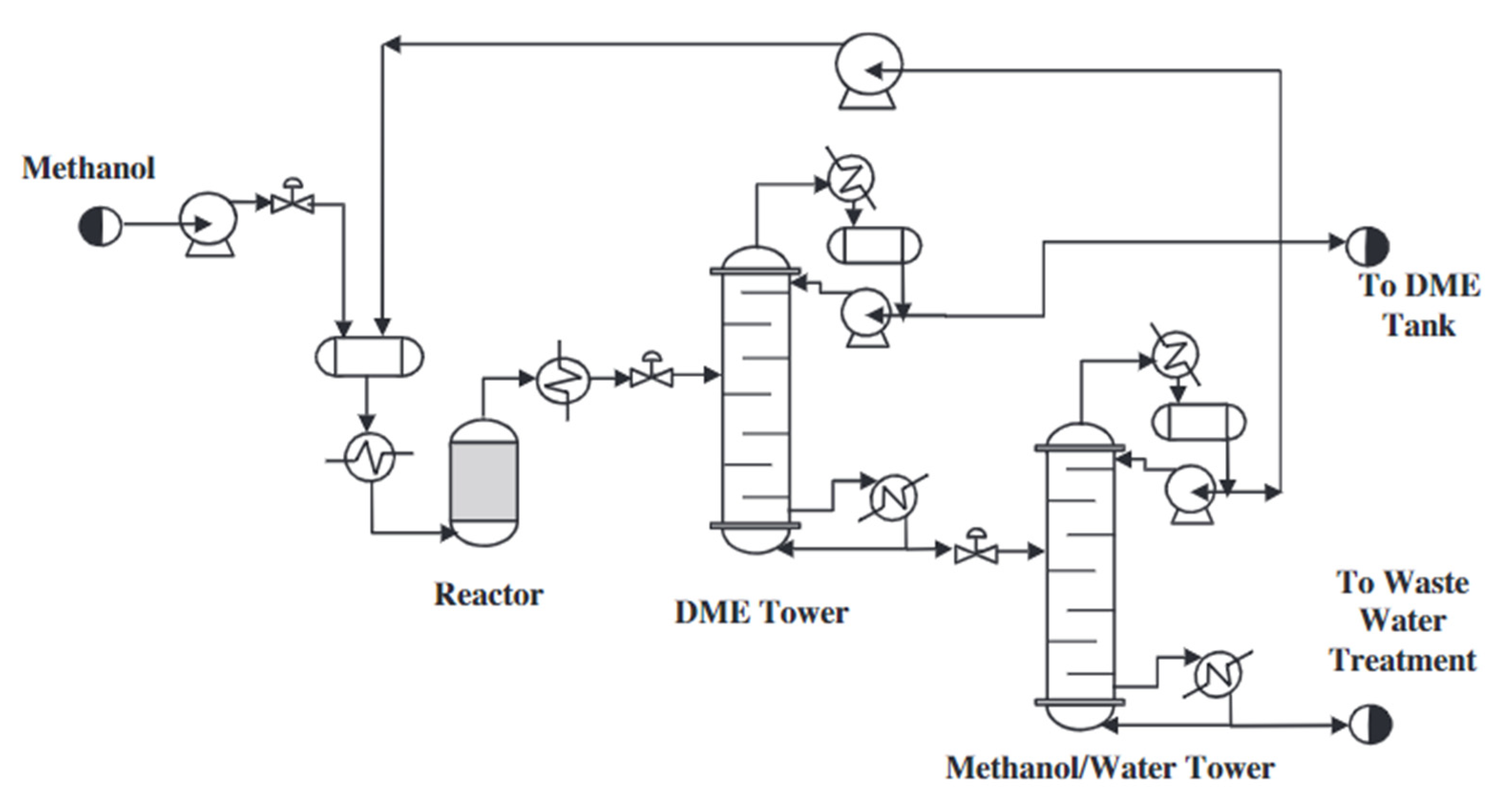
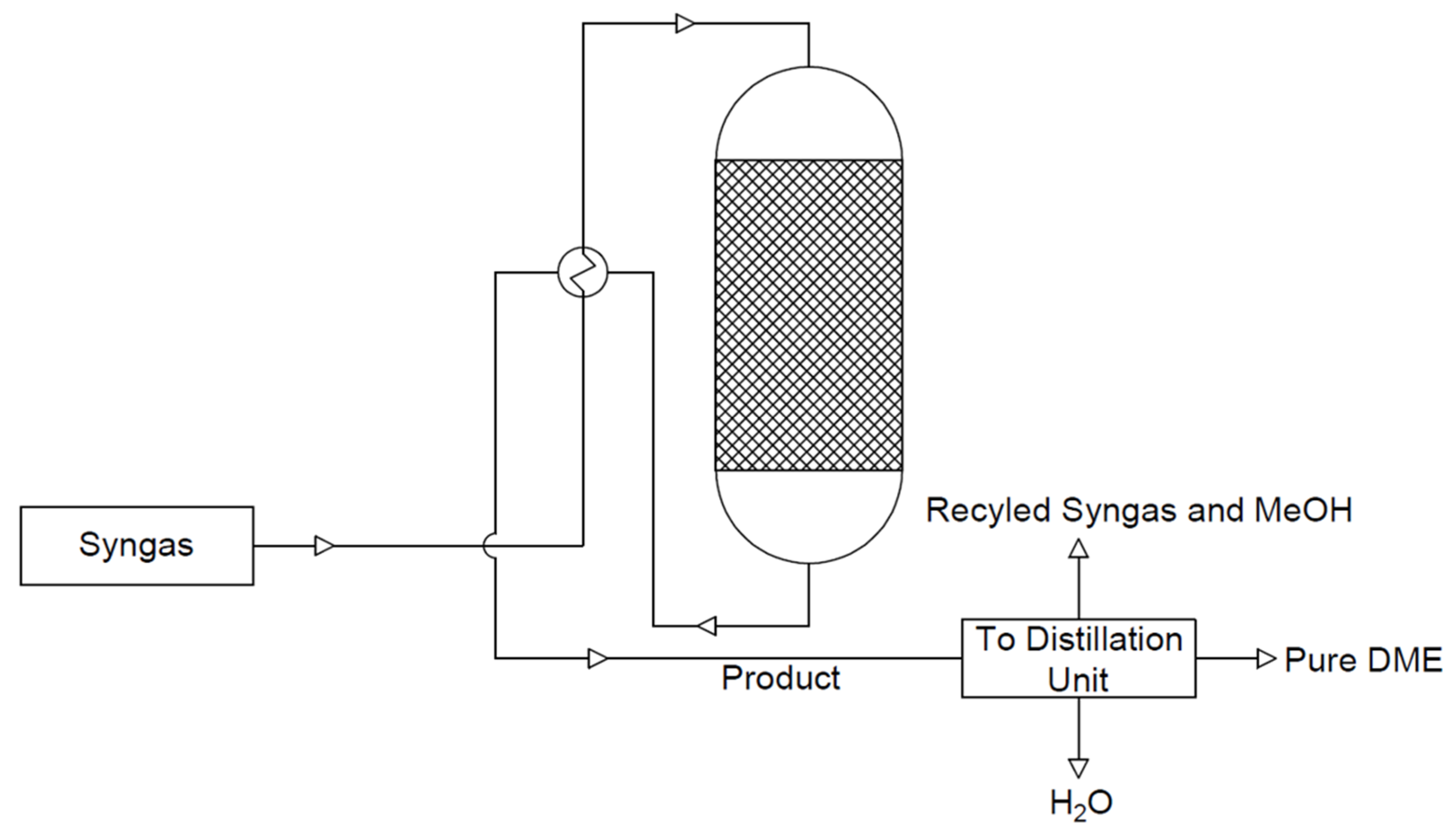
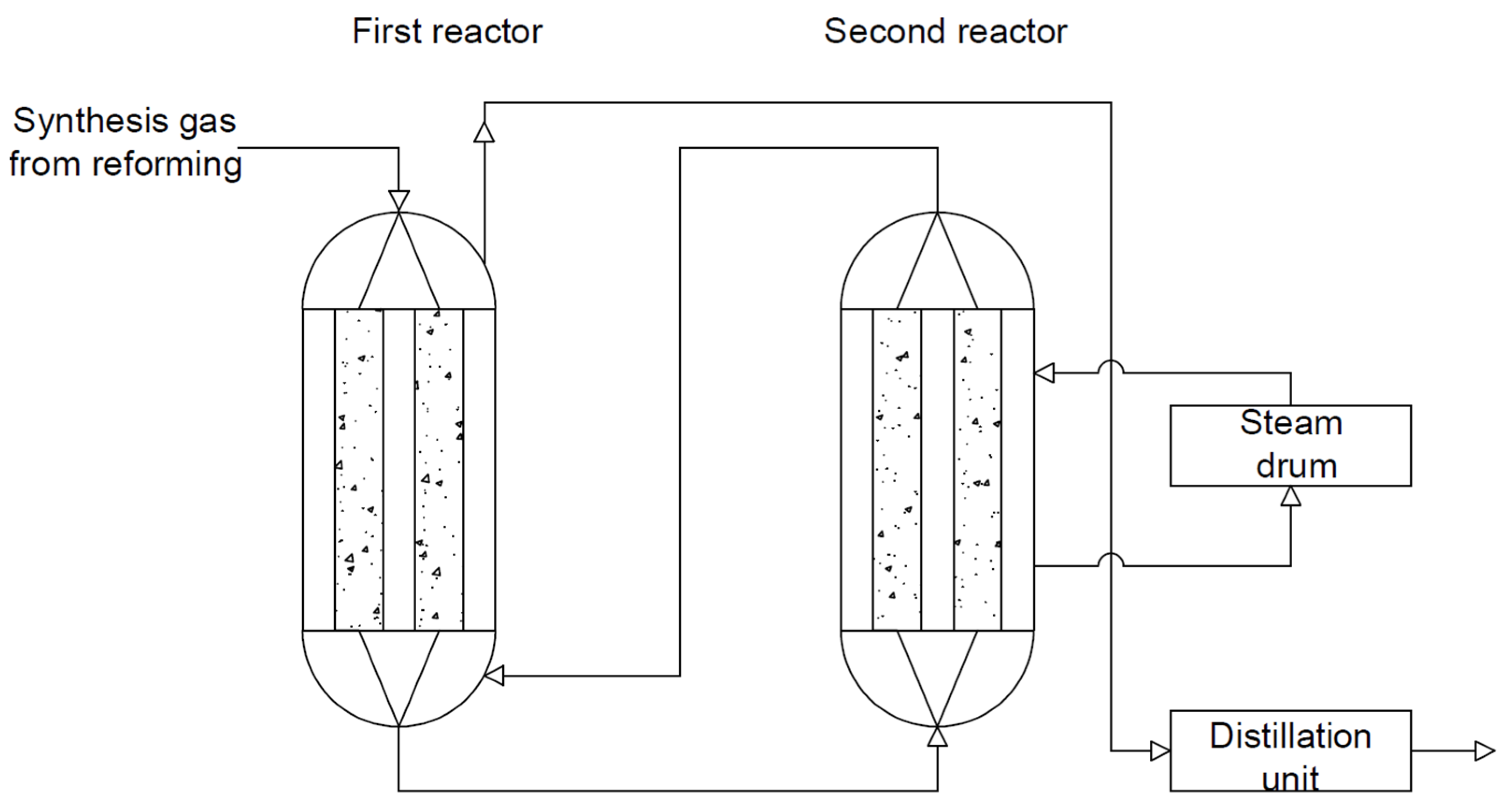
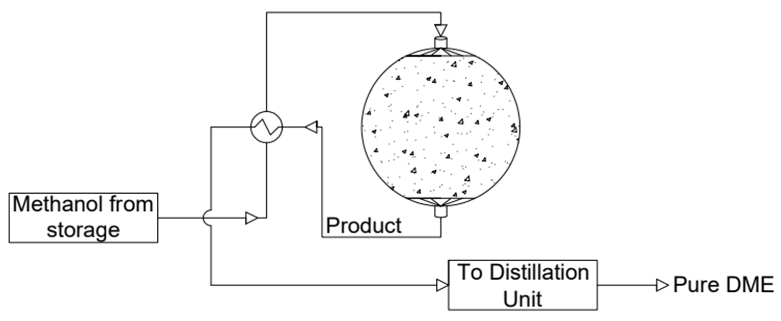
At present, dimethyl ether is produced on a large scale by a mixture of synthesis gases (CO and H2) in a two-step process. The reactions of methanol synthesis and dimethyl ether synthesis are conducted in two separate reactors. In the first stage, methanol is formed from a synthesis gas mixture with an appropriate volumetric ratio (Equation (5)) over a metal catalyst—Cu/ZnO/Al2O3. In the second step, the dehydration of methanol over an acid catalyst (Equation (6)) takes place [20]. The standard pressure and the temperature during methanol synthesis are in the ranges of 5.0–10.0 MPa and 220 to 280 °C, respectively [21]. The scheme of the system for the synthesis of dimethyl ether by the indirect method is shown in Figure 1. According to Figure 1, methanol is synthesised from the synthesis gas in one reactor; it is then purified and synthesised into DME in another reactor. The reactions take place as shown in the equations below (5). It is preferable to carry out this process at lower temperatures due to the exothermic reactions taking place and the resulting by-products, such as ethylene, hydrogen, carbon monoxide, and/or coke [9].
First-stage reactor: CO + 2H2 ↔ CH3OH ΔH°(298) = −90.6 kJ/mol
Second-stage reactor: 2CH3OH ↔ CH3OCH3 + H2O ΔH°(298) = −23.5 kJ/mol
- (a)
- Direct method of dimethyl ether synthesis
A single-step method has been proposed as an alternative to the two-step process. The one-step process combines these two reactions, i.e., methanol synthesis (Equation (5)) and its dehydration (Equation (6)) to DME, in one reactor with the use of a bifunctional catalyst. Hybrid catalysts require a combination of metal (responsible for the selective hydrogenation of carbon monoxide to methanol) and acid sites (to dehydrate methanol and produce DME). This solution allows for a reduction in the operating costs with higher syngas conversion and lower steam demand (with a lower H2/CO volume ratio). Additionally, the use of a single reactor without a purification unit and methanol transport allows for a reduction in the production costs. It also makes the entire process thermodynamically more favourable, since the conversion from synthesis gas to DME is a highly exothermic process, leading to an increase in both the carbon monoxide conversion and the DME selectivity [22,23,24].
Despite the many advantages of the one-step DME synthesis process, N. Mota et al. [25] claimed that the synthesis of dimethyl ether from synthesis gas should not be used for commercial purposes due to the ongoing site reaction. In this case, two reactions take place. The first one involves the conversion of carbon monoxide with water vapour (Equation (7)) to carbon monoxide (IV) and hydrogen. The second reaction is the reaction of carbon monoxide with hydrogen, in which dimethyl ether and carbon monoxide (IV) are generated (Equation (8)).
CO + H2O ↔ CO2 + H2 ΔH°(298) = −41.2 kJ/mol
3CO + 3H2 ↔ CH3OCH3 + CO2 ΔH°(298) = −245.8 kJ/mol
A better solution is to use a mixture of carbon dioxide with hydrogen instead of carbon monoxide. Due to thermodynamic considerations, the reaction with CO2 leading to DME is no longer as advantageous as that for CO, so the yield of DME generation is ultimately lower. Studies have shown that the low yield of DME synthesis is associated with a lower equilibrium constant for methanol formation from H2 + CO2 gases and is equal to K523K = 1.43∙10−5 [−] [26]. It is recommended that the hydrogenation of the carbon dioxide is carried out close to equilibrium conditions. High pressure is also preferred due to the reduction of the number of moles of H2, and CO2 used in the reaction, and it is preferable to operate at a lower temperature than standard at 100–250 °C, since a high temperature promotes endothermic side reactions, such as carbon monoxide and hydrogen conversion. The disadvantage of the process at low temperatures is the necessity to optimise the operation of the reactors, including the removal of water and the development of more active catalysts in the carbon monoxide (IV)-proving reaction. In the DME synthesis reaction with the participation of CO2, a large amount of water is produced, which is related to the highly competitive gas–water reverse-conversion reaction, which consumes CO2 and H2 leading to the lower selectivity of DME. The water generation can also inhibit the formation of methanol at the hydrogenation sites of the catalysts, since water molecules tend to be absorbed onto the surface of the catalysts, thereby blocking the active sites. Moreover, water can damage the structure of acid catalysts [24,25,26].
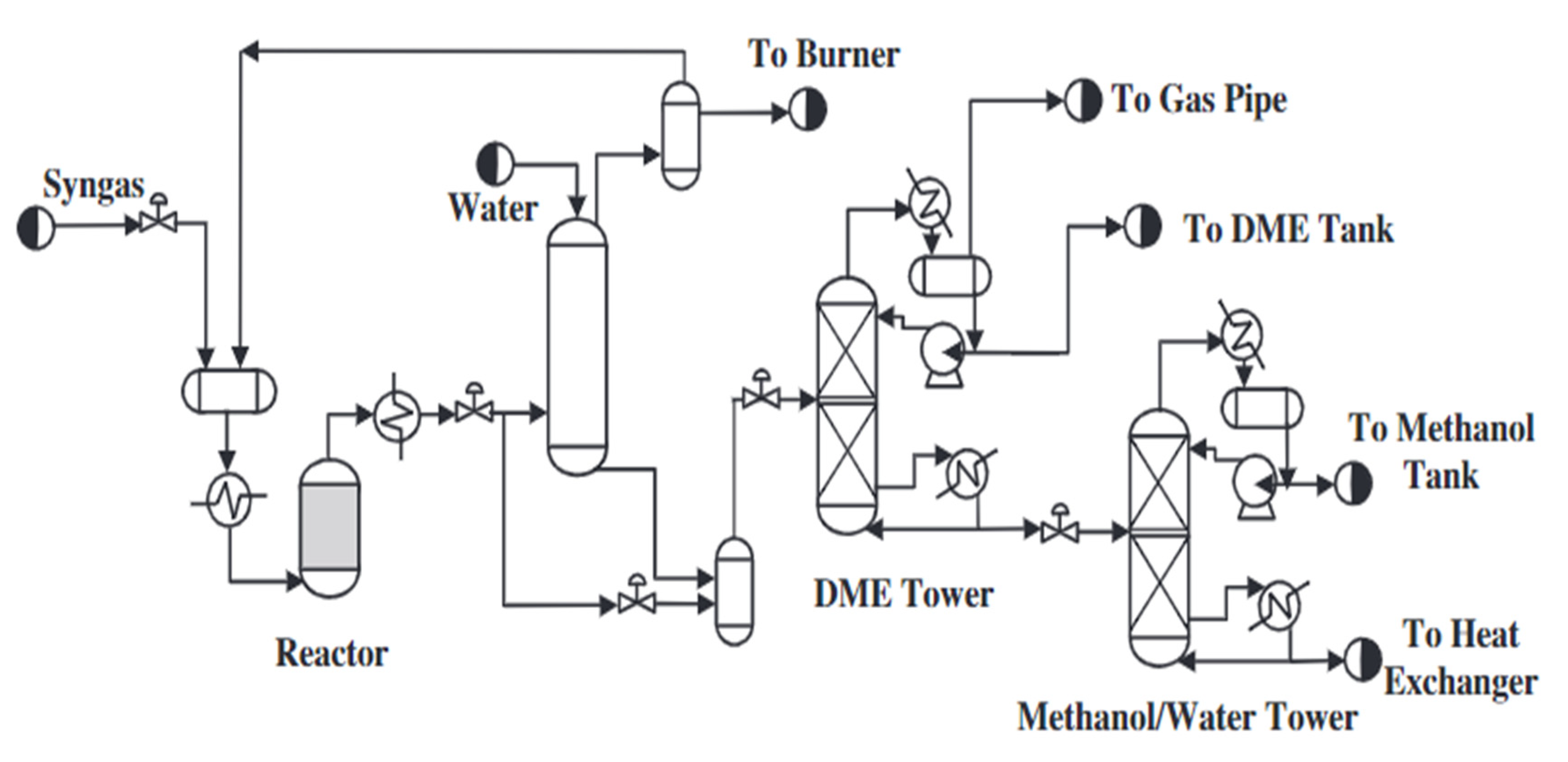
The scheme of the synthesis of dimethyl ether by the direct method is shown in Figure 2. The scheme below represents the synthesis of methanol and its dehydration to DME in a single reactor. The direct synthesis of DME from synthesis gas results from two main reactions, which are shown below ((9) and (10)). According to the reactions below, both the methanol synthesis and the carbon monoxide steam conversion reaction take place in the DME synthesis process. The former plays a key role in the DME synthesis process. CO2 is a by-product of the reaction, which can be used for methane reformation, in which the synthesis gas is reformed. The general reaction of the single-step DME synthesis is strongly exothermic; therefore, the temperature of the process should be properly controlled. Although the direct synthesis method causes little loss of natural gas, it is one of the most complicated chemical reactions.
2.2. Synthesis of Dimethyl Ether from Methane
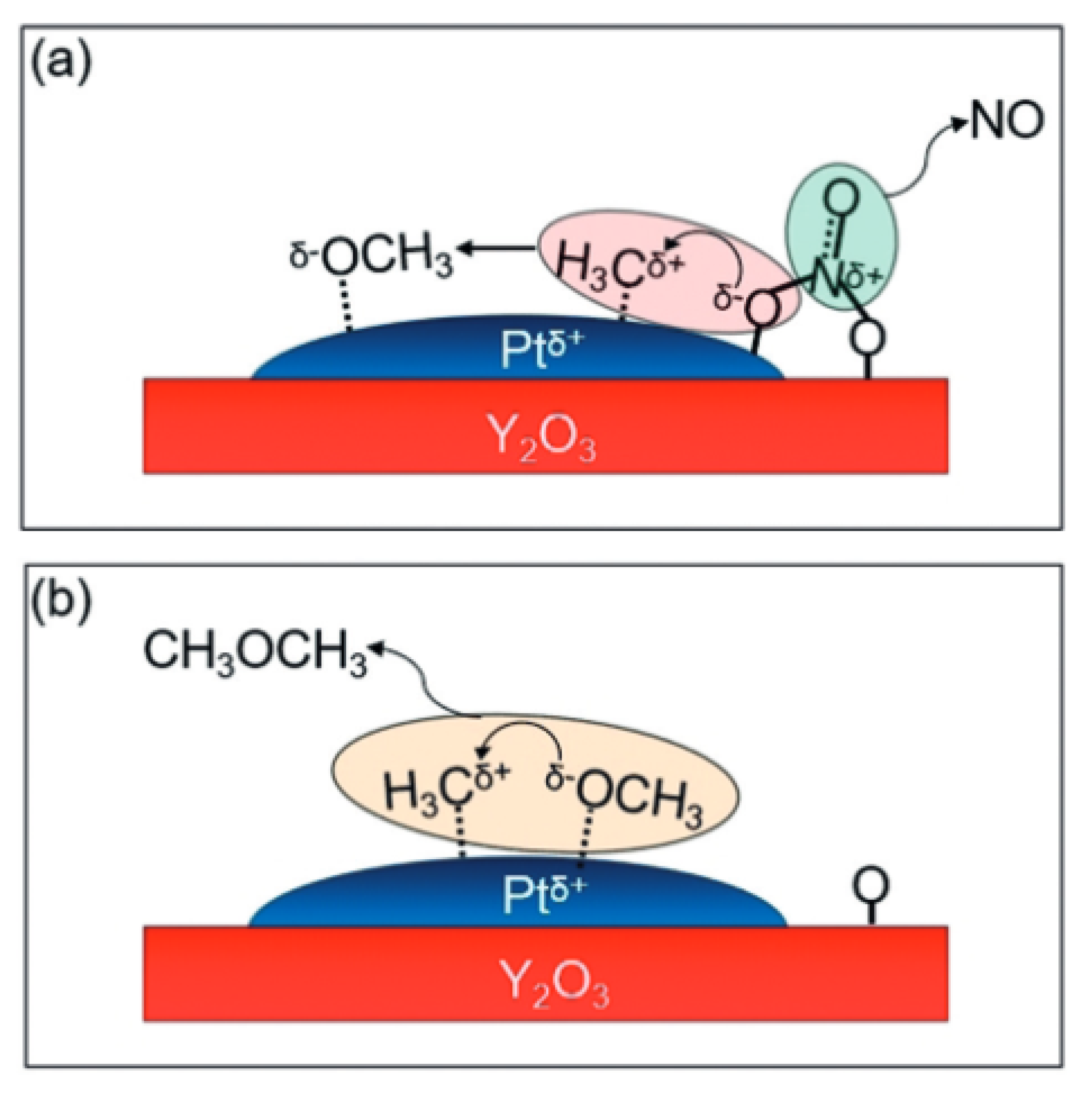
Another method of synthesis is the process of the partial oxidation of methane to dimethyl ether. It is a direct DME synthesis reaction without the formation of methanol as an intermediate. This type of process requires a strong oxidant to break the C–H bonds in methane and oxidise it further to ether. For this purpose, it is possible to use a mixture of NO and O2; with the use of such a mixture, it is possible to obtain NO + 1/2O2 = NO2 as a result of the reaction. This compound has strong oxidising properties that make it possible to obtain DME as the only product during the process. This is also due to its high selectivity towards ether. It is also necessary to select an appropriate catalyst on the surface of which the oxidation process takes place. Research is currently underway on the use of platinum-based catalysts. In the first stage, the methane carbocation reacts with NO3+ on the surface of the catalyst, as a result of which a methanol carbanion is obtained; additionally, NO is released from the surface of the catalyst. The second stage consists of the reaction of the formed methanol carbanion and methane carbocation, resulting in the formation of dimethyl ether, which is released from the catalyst’s surface. In this reaction, NO2 plays a transport function for oxygen, which itself is not directly involved in the oxidation process. Currently, the catalyst that performs best in this process is Pt/Y2O3, which exhibited the greatest activity at 350 °C and a pressure of 0.10 MPa. During the tests carried out under these conditions and the mixture of CH4:NO:O2 inert gas with a ratio of 20:1:1:78 and the catalyst in the amount of 0.3 g, it was possible to obtain DME in the amount of 110 µmol/(g⋅h). The low conversion of methane, at the level of 5%, resulted from the need to use an excess of it in order to prevent the formation of an explosive atmosphere in combination with oxygen [27,28] diagram below (Figure 3) shows the likely steps in the oxidation of methane to DME on the catalyst’s surface.
3. Structure and Modifications of DME Catalysts
In general, traditional catalysts consist of three parts: the support, the active part, and the promoter. The vast majority of catalysts used are solid, which do not form a homogeneous phase with the reactants or the reaction medium. However, in the literature, there are reports of the use of homogeneous catalysts to obtain dimethyl ether, e.g., the use of ionic liquids [29]. Each of the components plays a separate role in achieving the highest possible activity. The purpose of the support is to increase the surface of the active phase, and increase the mechanical and thermal strength. The support also contributes to the enhancement of the stability of the catalyst through the prevention of crystal growth and the aggregation of crystallites. It should have a high melting point. Moreover, the important features of the support are the concentration of crystallites. The most-used materials as catalyst supports include SiO2, α-Al2O3, γ-Al2O3, Cr2O3, MgO, and CaO [30]. The active ingredient directly accelerates the reaction. It is the source of active centres on which transition complexes are formed. The most popular active phases include metals, such as copper, platinum, nickel, silver, zinc and nickel oxides, and metal sulphides. The proper selection of the active phase is crucial in the development of the catalyst. The third component of the catalyst is a promoter that modifies the catalyst’s properties, such as its activity, stability, and selectivity. The most-used promoters include magnesium oxide, zirconium dioxide, and hydrogen chloride. Promoters are added in small amounts, but they increase the activity and/or selectivity. The promoter may accompany the active substance or the carrier. Moreover, promoters, such as sodium or potassium, are added to prevent coke formation through the modification of catalyst acidity [31,32,33]. Due to the higher selectivity and regeneration, heterogeneous, rather than homogeneous, catalysts are used much more often in practice.
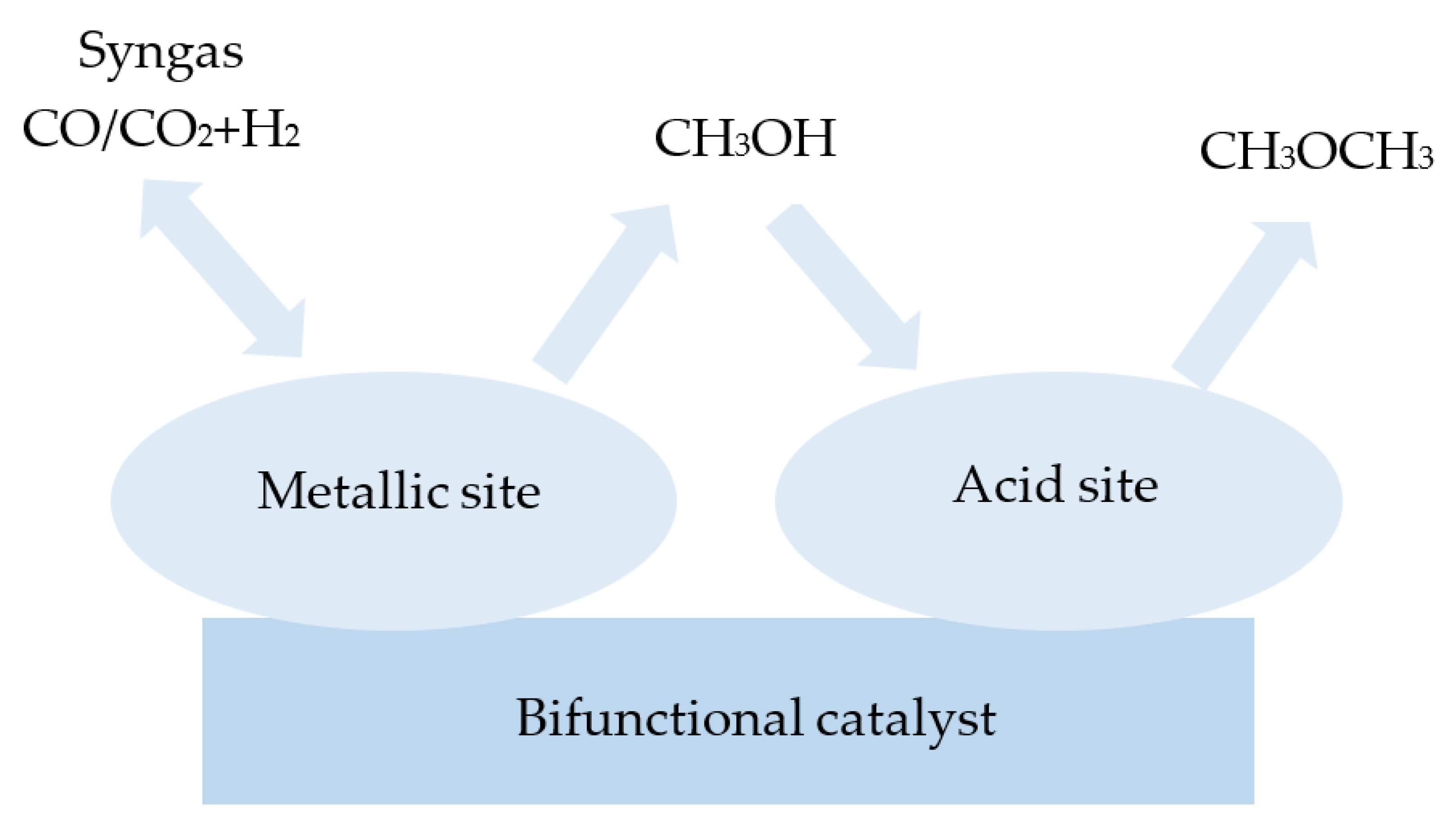
A one-step synthesis of dimethyl ether involves bifunctional catalysts. They consist of a metallic part and an acidic solid part. The metallic part is used to synthesise methanol, while the acid part is used to form dimethyl ether through methanol dehydration. The operating temperature of these catalysts ranges from 523 to 673 K, and the operating pressure is up to 10 MPa [34]. Among the examined metallic phases, CuO/ZnO/Al2O3 (CZA) catalysts are characterised as having the highest activity. Typically, CZA is prepared by a co-precipitation method, and this is mostly composed of around 50–70% of CuO, 20–50% of ZnO, and 5–20% Al2O3. In Figure 4, the general structure of a bifunctional catalyst consisting of a metal and an acid part is presented. Metallic copper clusters are active sites for the conversion of carbon monoxide with hydrogen and for the synthesis of methanol. The copper surface area influences the conversion of the synthesis gas to methanol [35]. Zinc oxide provides enough active sites for gaseous reactants by keeping active copper in proper dispersion. However, it has been found that excess zinc oxide has a negative effect on acidity. Moreover, metals, such as aluminium, are also added to increase the surface area and dispersion of the copper [36,37]. Aluminium and zinc oxides have also been found to prevent the sintering of the copper particles. Nevertheless, it was observed that the excess of copper and aluminium oxides increases the activity of the catalyst, as opposed to zinc oxide, since its excess causes a decrease in the activity of the catalyst [38].
Copper catalysts are mainly prepared using the co-precipitation method [39]. Among factors that influence the catalytic activity of copper catalysts are the size of the copper particles and their dispersion. They depend on the preparation conditions, including the molar ratio of copper to zinc, calcination temperature, and type of precipitant [38,40,41,42]. It has been shown that a lower ratio of copper to zinc has a positive effect on the conversion of carbon monoxide with water vapour, because it causes the presence of more active sites [43]. To enhance the yields and selectivity of dimethyl ether generation, CZA catalysts have been the subject of continuous research on their modification. The most widely used modification method is the addition of another metal to increase the activity or selectivity and to improve the dispersion of copper particles. Among the reported additives, magnesium [44,45], manganese [21,46], zirconium, [33,47,48], chromium [21,46], iron [49], gallium, indium, lanthanum [50], lithium [51], and titanium [52] oxides or salts may be distinguished.
Ren et al. [53] modified the CZA catalyst with the hydrated salt of zirconium nitrate (IV) using the co-precipitation method, obtaining the catalyst CuO/ZnO/Al2O3/ZrO2 (CZZA) with a mass ratio of 4:2:1:0.5. As an acidic part, H-ZSM-5 with a SiO2/Al2O3 molar ratio of 23:1 was used. The process was carried out in the temperature range of 200–260 °C and under a pressure of 2.76 MPa. Studies have shown that the addition of zirconium increases the methanol yield and DME generation selectivity. The methanol yield was 12.4% at a temperature of 220 °C and under a pressure of 2.76 MPa. The selectivity of DME synthesis was on the level of 18.3% at a temperature of 240 °C under the same pressure. For comparison, a CZA catalyst with HZSM-5 with a SiO2/Al2O3 molar ratio of 23:1 was used. The methanol yield decreased from 12.8% to 10.8% after 100 h of the process. The characterisation of the catalysts showed that CZZA was less stable during DME synthesis than during methanol synthesis. It was shown that there was a reduction in the specific surface area after the process. In addition, coke was detected on the H-ZSM-5 catalyst, which caused the deactivation of the bifunctional catalyst. Kosova et al. [47] examined the effect of CZA catalyst modification with zirconium and chromium, namely CZA-Zr and CZA-Cr, respectively. The CO conversion was 60% for the CZA/H-ZSM-5 catalyst, 83% for the CZA-Cr catalyst, and 68% for the CZA-Zr catalyst. For the above catalysts, the DME yields were 18%, 15%, and 11%, respectively. The process was carried out at temperatures of 240 °C, 240 °C, and 220 °C. The pressure was 3 MPa. A tubular reactor was used for the tests.
The efficiency of dimethyl ether synthesis strongly depends on the characteristics of the catalysts. For bifunctional catalysts, different aspects should be considered. A sufficiently high activity during methanol synthesis is influenced by defects and changes in the morphology of the copper particles, their dispersion, crystallite size, and interactions with zinc atoms. The catalytic activity is also directly influenced by the dispersion of copper, the reducibility of CuO to metallic copper, the size of the copper grains and their type, lattice deformation, the crystalline phase of the carrier, and the method of mixing. The method of its preparation is also a factor influencing the structure of the catalyst. Among the most-used commercially used methods, the co-precipitation method is predominant. However, it is time-consuming as the ageing stage reaches several hours, and the method also requires the use of large amounts of water in the washing stage. Incorrectly performing any step has a negative effect on the catalytic activity of the catalyst. An important element is the development of effective, fast, and cheap methods of catalyst synthesis [54].
The acid part most often consists of Al2O3 [55,56,57], HPA [38], HZSM-5 [41,42,43,44], HY [6], MCM [53], ion exchange resins [42,58], or H-β [43,59,60]. Acid catalysts contain acid–base centres, both Brønsted and Lewis, and redox-type (electron-withdrawing and electron-donating) centres [61]. The total number of acid sites and their strength significantly affect the final catalytic activity [32,62]. It has been proven that weak and medium acid sites are responsible for the dehydration of methanol, while strong acid sites are responsible for the formation of more olefins. Among the catalysts used for the dehydration of methanol, γ-Al2O3 is most often used due to its thermal properties, mechanical stability, high surface, selectivity, and relatively low cost [21,63,64]. The next group of the most-used catalysts are zeolites. Used for its high selectivity, catalytic activity at low temperatures, and better stability in the presence of water in comparison with γ-Al2O3, zeolite H-ZSM-5 is one of the best-examined and most frequently used catalysts in DME synthesis due to its skeleton topology, hydrothermal stability, and simplicity of physicochemical property modification, such as acidity or texture. The ZSM-5 framework consists of two intersecting channel systems, with one straight line parallel to (010) and the other sinusoidal running parallel to the (001) crystal planes. The entrance to the pores is limited by a 10-membered ring with a diameter of about 55 μm. The most popular methanol conversion products, in addition to DME, are also olefins, paraffins, and aromatics. The channels are wide enough, even for the diffusion of tetramethylbenzene, and the intersections of the channels are suitable for cyclisation reactions and intermolecular hydride transfer [65,66].
In the case of zeolites, the acidity depends on their structure and the Si/Al molar ratio. The more commonly used catalyst is H-ZSM-5 due to its more hydrophobic nature than that of Al2O3. The Al2O3 catalyst loses activity rapidly due to its hydrophilic nature. However, the use of temperatures above 270 °C causes the formation of undesirable by-products—hydrocarbons. This is due to the high acidity of zeolites. To improve DME’s selectivity and methanol conversion, the number of acid sites that are responsible for total acidity and its amount should be reduced [34]. The H-ZSM-5 catalyst is the most-used catalyst for the dehydration of methanol, because its structure has large amounts of acidic Bronsted sites and is hydrophobic in nature, which makes it much more resistant to poisoning caused by the presence of water. The presence of strong acid sites contributes to the formation of undesirable light hydrocarbons and the deactivation of the catalyst due to the formation of coke. However, the smaller size of the crystallites of this zeolite and the smaller number of Bronsted acid centres on its outer surface in relation to alumina determine the activity of this catalyst. It is important to choose the Si/Al ratio appropriately, as it directly affects the course of the reaction and ultimately the DME activity and selectivity. It has been found that the greater the amount of aluminium, the greater the number of acid centres, and, ultimately, the greater the activity of the catalyst. In a study conducted by J. Abu-Dahrieh et al. [21], three catalysts for methanol dehydration with different SiO2/Al2O3 ratios were tested: NH4-ZSM-5 with SiO2/Al2O3 mass ratios of 23 and 80, H-ZSM-5 catalyst with a SiO2/Al2O3 ratio of 80, and γ-Al2O3. The processes were carried out at two temperatures—200 and 250 °C—under a pressure of 2.0 MPa. As a metallic part, CuO/ZnO/Al2O3 catalysts were used. The processes were performed with the following catalyst ratios: CZA/HZSM-5 3:1, CZA/NH4-ZSM-5 3:1, and CZA/γ-Al2O3 1:1. The conducted research has revealed that the most stable catalyst is H-ZSM-5. Additionally, high activity was obtained with CZA/HZSM-5 catalyst at a relatively low temperature. It was also observed that the catalyst was slowly deactivated because of the coke formation. In contrast, the DME yield decreased from 18.5% to 14.1%.
Chlorination and fluorination have been proven to be two methods that can effectively control acidity. Chlorinated catalysts show greater activity and selectivity of DME formation compared with fluorination. On the other hand, performing fluorination and chlorination simultaneously allows obtaining higher catalytic activity. The conducted research has also shown that ultrasound also positively influences the improvement of activity, which is probably caused by the textural and acid changes that occur during ultrasound irradiation [67].
Similar to the metallic part, the acidic part of the catalyst may be also modified by adding metal compounds. The purpose of doping with other elements is the modification of the strength of the acid sites. The methods of reducing the number of strong active centres include the treatment of zeolites, e.g., ZSM-5, with ammonia or alkylamine, followed by thermal treatment. It is also recommended to use oxides of sodium, magnesium, lanthanum, calcium, zircon, aluminium, or zinc by wet impregnation with solutions of these salts, which increase the selectivity of DME and the stability of the catalyst [21,68,69,70,71,72,73]. Additionally, it has been shown that methanol conversion and the improvement of DME selectivity can be increased by reducing the crystal size of the dehydration catalyst’s part [66]. M. Z. Pedram et al. [74] modified the HZSM-5 catalyst with various metals, including 5% of Mg, Zr, Na, and Al, and 5%, 10%, 20%, 40% and 60 wt.% of Zn. The reaction was carried out at a temperature of 230 °C and 1.9 MPa for 4 h. The process was carried out in a slurry reactor. The research showed that the best results were obtained for the Zr-modified H-ZSM-5 catalyst. Zinc contents above 10% reduced methanol conversion. It can be concluded that, in this range, the zinc oxide crystallised and was not highly dispersed. Zinc oxide with contents of 5% and 10% were bound to the hydroxyl group and formed Zn (OH)+, which resulted in an increase in the number of acid sites and a reduction in the number of Bronsted sites. A catalyst that contains a high ZnO percentage above 10% has lower numbers of both acid and base sites. H-ZSM-5 also proved to be highly selective for the dewatering of methanol. The research showed that the catalysts modified with zirconium had the highest stability with H-ZSM-5. They achieved 91% of methanol conversion and 91.1% of DME yield. Moreover, it has been proven that the conversion of methanol to DME is dependent on the degree of acidity, and the selectivity towards DME and the stability of the catalyst are dependent on the strength of the catalytic sites. In summary, methanol conversion is lower for the H-ZSM-5 catalyst with the addition of zinc at contents above 10%. The worst results were achieved for ZnO2/H-ZSM-5 with 60 wt% of zinc, resulting in 22% methanol conversion and 22.1% DME yield. They also carried out the process with Al2O3/H-ZSM-5 catalyst. The methanol conversion was 56% and DME yield was 56.1%.
4. Characterisation Results Indicated Coke Formation
The results for different types of catalysts and post-process reactors are presented below. The focus is mainly on the results obtained that confirm the presence of coke as the main cause of deactivation.
- (a)
- Thermogravimetric analysis—TGA
The amount of coke deposited on the catalysts after the process was determined by thermogravimetric analysis (TGA). The analysis was carried out with a temperature rise from 25 to 900 °C and a heating rate of 10 °C per minute under air flow. At temperatures below 200 °C, mass loss is caused by the thermal desorption of adsorbed water. In addition, mass loss at temperatures from 200 to 500 °C is caused by the removal of amorphous carbon through the oxidation of CO to CO2, while fibrous and graphitic carbons undergo gasification at higher temperatures [75]. T. K. Obukhova et al. [76] carried out tests in a tubular-bore reactor (FBR) and in a slurry suspension reactor (SLR) using the Mg/ZSM-5 catalyst. The TGA tests showed that, at a temperature of about 100 degrees, water desorption and the degassing of weakly bound hydrocarbon-derived impurities take place in the pores of the catalyst. At 300 °C, mass loss also occurs. This stage is associated with the removal of the decomposition products of the dispersion medium. These are difficult to remove from the solid phase of the catalyst after the reaction. In addition, at 500 °C, the oxidation of high-temperature coke sludge occurs, accompanied by the evolution of gaseous products.
R. Liu et al. [77] conducted a test with an encapsulated CZA catalyst deposited on a HZSM-5 membrane. They reported that the mass loss in the 50–300 °C range was due to physical resorption on the surface of the encapsulated catalyst and the desorption of structural water. The mass loss in the temperature range of 300–600 °C can be attributed to residual model molecules from the capsule catalysts. The mass of these catalysts increases with increasing temperature, which is attributed to the coke present on the HZSM-5 membrane. Furthermore, a loss of catalyst mass was found in the temperature range of 640–750 °C, which was attributed to the combustion of coke during thermogravimetric analysis. At 800 °C, a mass loss of 4.3% was observed, indicating high thermal stability.
Research conducted by Chen W. [61] demonstrated that the increase in the TGA curve in the temperature range of 160–413 °C is a consequence of the oxidation of Cu to CuO.
- (b)
- XPS
The figure below shows the XPS results for CuZnOZrO2 [78]. XPS analysis indicated a significant reduction in acidity for the SO42/ZrO2 (SZ) catalyst. This is attributed to the carbonaceous precipitate blocking the acid sites. In addition, the addition of copper reduces the number of strongly acidic sites, thereby weakening the interaction of the carbon moieties with the catalyst surface. Furthermore, copper’s ability to dissociate H2 and hydrogenate may prevent coke deposition.
It was found that, for the CuO–Al2O3/CuAl2O4 catalyst, the amount of Al2O3 decreased by 20.9% and that of CuAl2O4 increased by 79.1%. These changes show that Al2O3 reacts with Cu atoms to form CuAl2O4 during the catalytic reaction. In addition, unbound CuO particles are dispersed on the surface of fresh CuO–Al2O3, thus providing active sites for methanol decomposition During the reaction, unbound CuO particles are reduced to Cu by reacting with H2, which is derived from methanol decomposition. These newly formed sites are considered active sites for methanol synthesis [79].
- (c)
- XAFS
V. Vargheese et al. used a Pt/Y2O3 catalyst and ran the process using methane as a substrate, bypassing the formation of methanol. The XAFS results showed that there was a strong interaction between Pt and Y2O3. Pt was shown to be in a partially oxidised state in Pt/Y2O3 and a partially metallic state in Pt/SiO2. It was confirmed that DME is only formed in the presence of Pt and NO+O2, but a large part of NO is converted to NO2. Importantly, the concentrations of NO and NO2 were equal to the initial concentrations, and no N2 was formed. Thus, it was concluded that NO and NO2 act as oxygen atom transporters for the partial oxidation of CH4 [28].
- (d)
- SEM
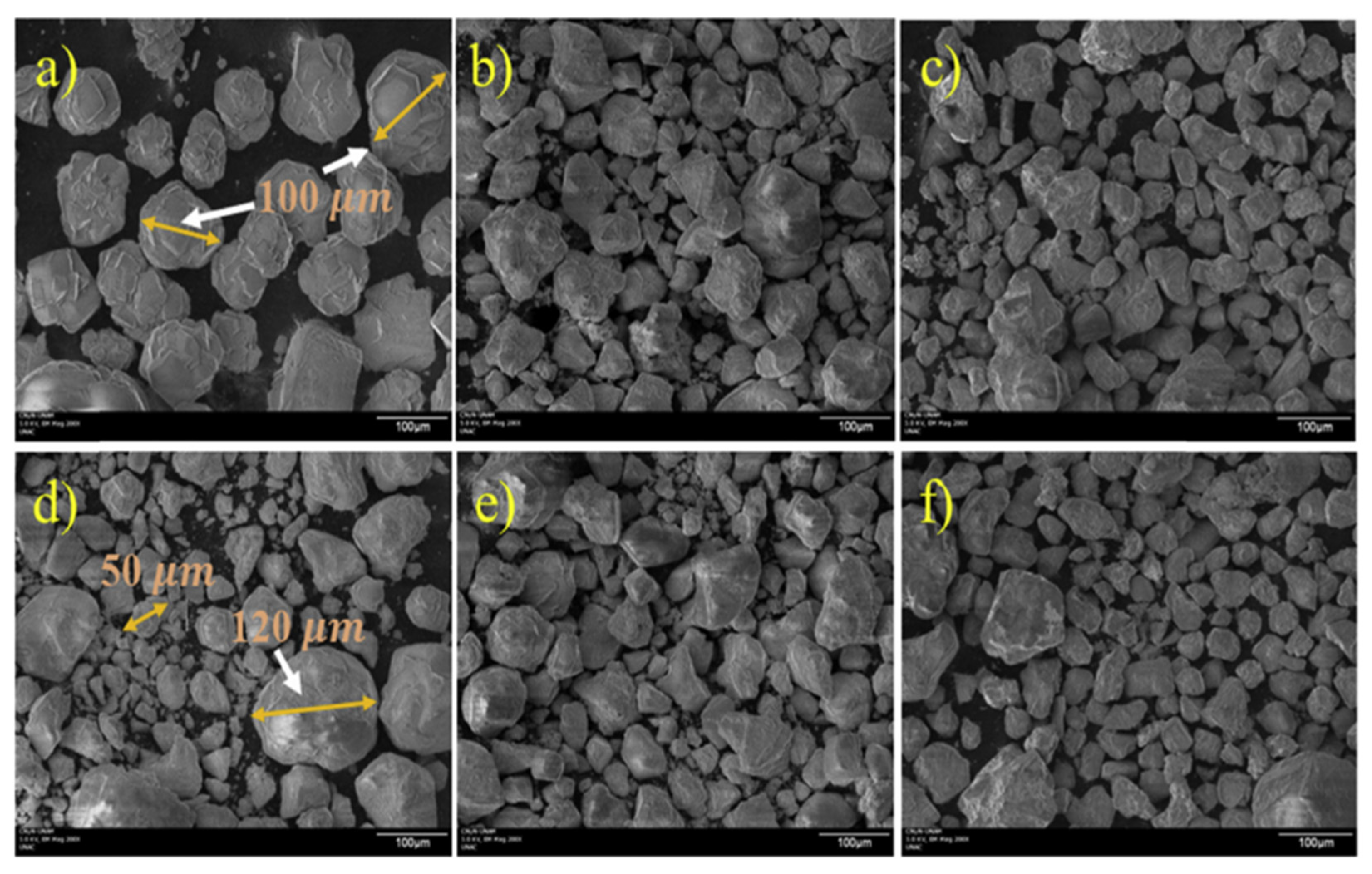
The SEM images (see Figure 5) show no apparent change in morphology during the reactions from 10 to 720 h. The morphology and particle size of the catalyst can cause deactivation [80].
The figure below shows the results of SEM analysis for the CuO-Fe2O3/γ-Al2O3 catalyst. It is observed that, after the reaction carried out at 290 °C, the catalyst presents much smaller agglomerates than it did before the reaction [81].
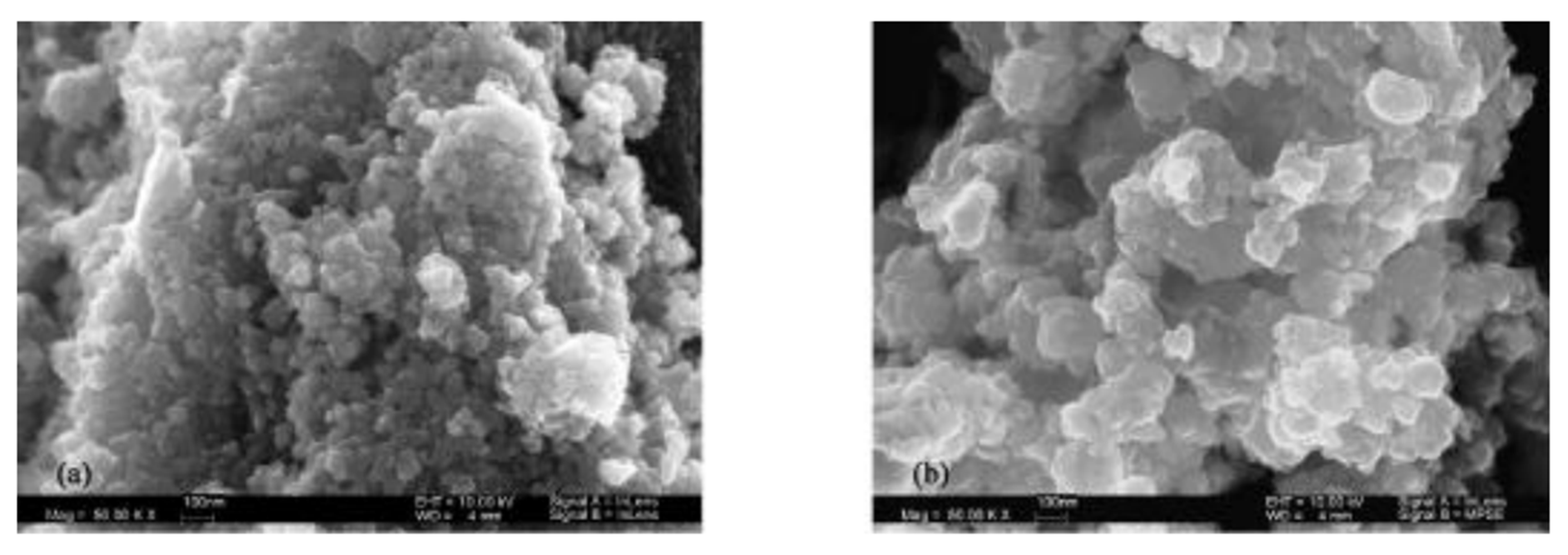
The figure (see Figure 6) below shows SEM images of the fresh catalyst and after the process. For the fresh catalyst, the diameter of the crystalline grains was about 30 nm and the grains were well-dispersed. In contrast, after the process, the average grain size increased to 50 nm and much larger particle aggregates were noted [82].
- (e)
- XRD
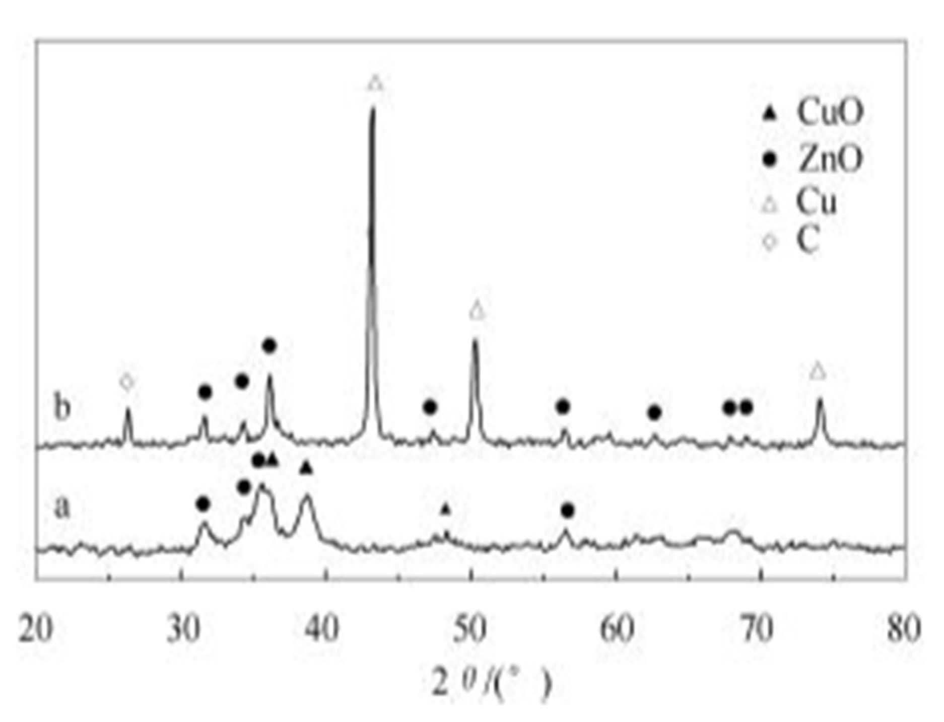
The X-ray powder diffraction method is used to compare the structural changes in the crystal phases of catalyst constituents. In most reports, the XRD results allow for the determination of copper oxide phase transformation to copper, changes of Cu and Zn into hydroxyl–carbonates, and the detection of graphitic carbon deposited on the surface after the catalytic process. In the case of the acidic part of the catalysts with crystallinity, a loss of the crystalline phase may indicate the leaching of components of that phase. Dong-Sheng et al. investigated the structural changes of a Cu/ZnO/Al2O3 catalyst for DME synthesis using the XRD method. The study by W. Dong-Sheng et al. showed that XRD peaks attributed to copper were absent before the catalytic process (see Figure 7). The peaks attributed to the copper phase indicated the copper oxide form. For spent catalysts, the appearance of peaks for copper and the disappearance of files for copper oxides were observed. The deactivation was attributed to the growth of copper crystalline grains, and the agglomeration became noticeably larger. Moreover, peaks attributed to graphitic carbon were also present, indicating the coking of the catalyst’s surface [81]. Similar results were observed by Chiang et al. [79].
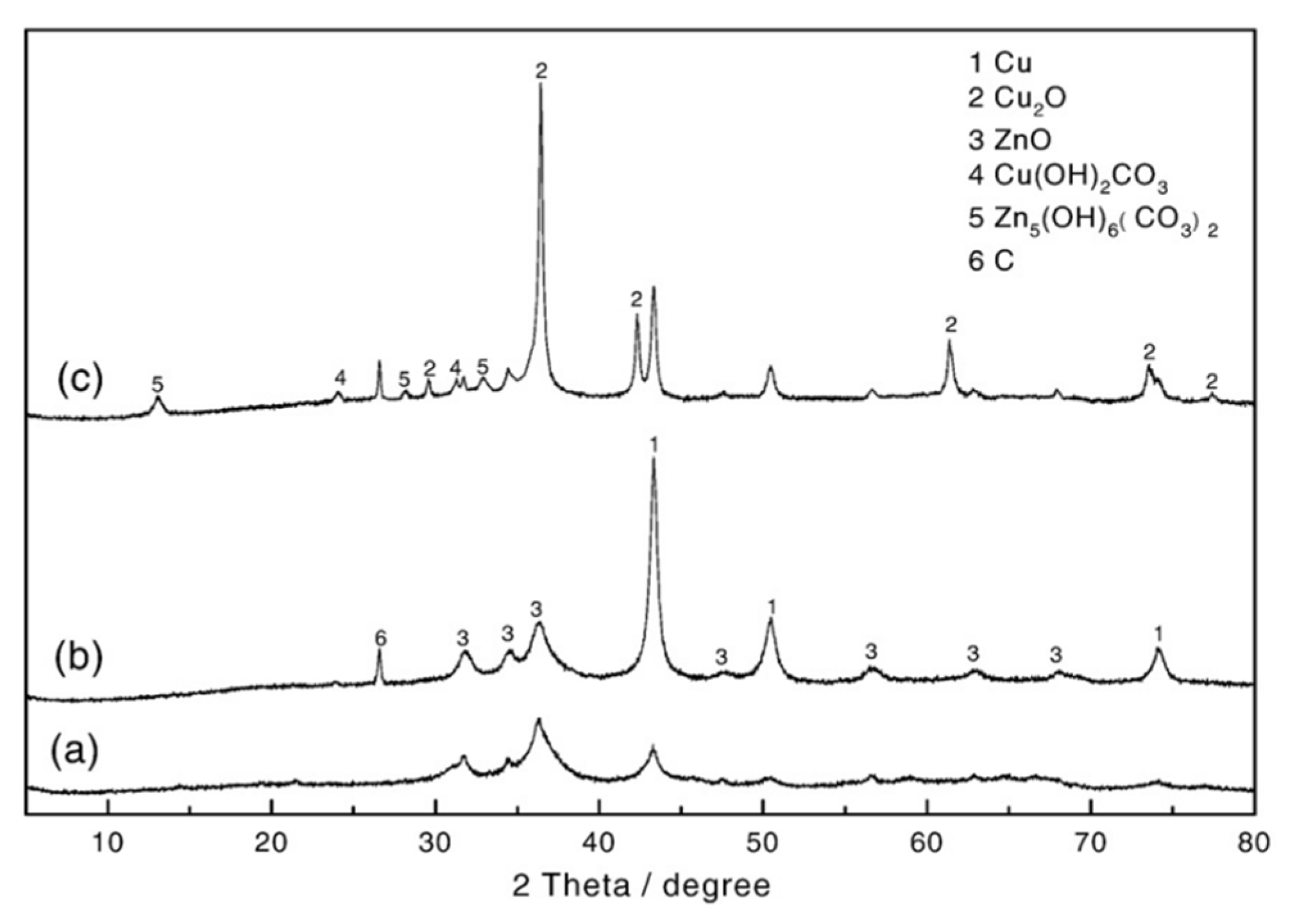
Wang et al. [83] investigated the effect of water addition on one-step DME synthesis using copper (Cu/ZnO) and alumina (γ-Al2O3) catalysts in a slurry reactor system. They evaluated the effect of H2O on the process effectiveness and structural changes of copper catalysts. Based on XPS and XRD techniques, they found the deactivation origin from the losses of Al and Zn elements due to hydrothermal leaching, transformation of copper particles into Cu2(OH)2CO3 species, and the loss of synergetic contact between Cu and ZnO due to ZnO-> Zn5(OH)6(CO3)2 transformation, increasing in the copper crystal size, and carbon deposition. The results are presented on the below Figure 8.
Ch. Lung Chiang et al. [79], using the XRD technique, showed that, for the CuO–Al2O3 catalyst with CuAl2O4, an increase in the number of copper particles occurs after the reaction due to the reduction of the particles to Cu. These particles are reduced to Cu upon contact with H2, formed from the decomposition of methanol. The formation of H2 is attributed to the occurrence of methanol decomposition in the CuO active sites, as H2 is one of the substrates.
- (f)
- In situ methods
The deactivation of catalysts as a result of coking, leaching, sintering or oxidation has its source in the reaction mechanism. Therefore, it is essential to track the individual changes taking place on the catalyst’s surface during the catalytic reaction. The study of changes taking place on the catalyst’s surface is possible with the use of in situ spectroscopic methods, including XRD and FTIR methods. Kabir et al. [84] investigated the structural changes in the commercial CuO/ZnO/Al2O3/MgO catalysts as the metallic part combined with commercial γ-Al2O3 as the acidic part during DME synthesis using synchrotron powder diffraction at different temperatures. Up to 250 °C, no changes were observed. Above 250 °C, the transition from CuO to Cu was observed. The intensity of the XRD peak corresponding to the Cu (1 1 1) direction and, therefore, the crystalline size were measured. It was found that along, with the temperature rise, the crystalline size gradually increased from 8.5 nm to 15 nm at 250 °C and 500 °C, respectively. No changes were observed for the methanol dehydration part, γ-Al2O3, indicating the structural changes in the metallic part as the main factor of catalyst deactivation. Peaks attributed to graphitic carbon were also found, indicating the coking of the catalyst’s surface.
Miletto et al. [85] investigated the characterisation of a Cu/ZnZr/ferrite catalyst during the synthesis of DME via the hydrogenation of carbon dioxide using in situ FTIR analysis. They found that the catalyst underwent the deactivation process due to the loss of acidic sites. No water or carbon compounds were detected; thus, it was concluded that the deactivation of the catalysts is associated with the migration of the copper zeolite’s surface to zeolite internal channels. In situ FTIR analysis was used by Chiang et al. [79]. They investigated the formation of organic species at the CuO/Al2O3 catalyst surface during the reaction of methanol dehydration to DME at 150 °C, 250 °C, and 350 °C under 50 bar. The measurements were performed at selected time intervals during the reaction. They investigated the formation of DME and formic acid during the reaction. It was found that, at lower temperatures (150 °C), the formation of HCOOH was favoured, while the highest values of the obtained dimethyl ether were observed at a temperature of 250 °C.
5. Reactors Configurations for DME Synthesis
The reactor systems applied for DME synthesis include both conventional and high-tech reactors. Among the conventional reactors’ configurations, fixed bed reactors, slurry reactors, and fluidised bed reactors may be distinguished. The currently developing new systems for DME synthesis are intended to solve the problem of deactivation and/or catalyst loss during the processes.
- I.
- Conventional reactors
- (a)
- Fixed-bed reactor
A fixed-bed reactor is most widely used for direct DME synthesis due to its simple and cheap design. The use of this type of reactor facilitates the contact between the catalyst phase and the reactant phase, which flows through the bed with the catalyst. The catalyst is immobilised in the form of a solid layer on the inner wall of the reactor. Figure 9 shows an example of a fixed-bed reactor. The disadvantage of using this reactor is the necessity of the continuous recirculation of the reactants and the associated operating costs. This is due to the low process efficiency of a single run. Another issue that needs to be addressed is the implementation of temperature control and cooling systems due to the exothermic nature of the DME synthesis reaction. Conducting the DME synthesis at temperatures above 300 °C leads to the deactivation of the metal catalyst through the deposition of coke on the walls of the reactor [76,86,87,88].
- (b)
- Fluidised bed reactor
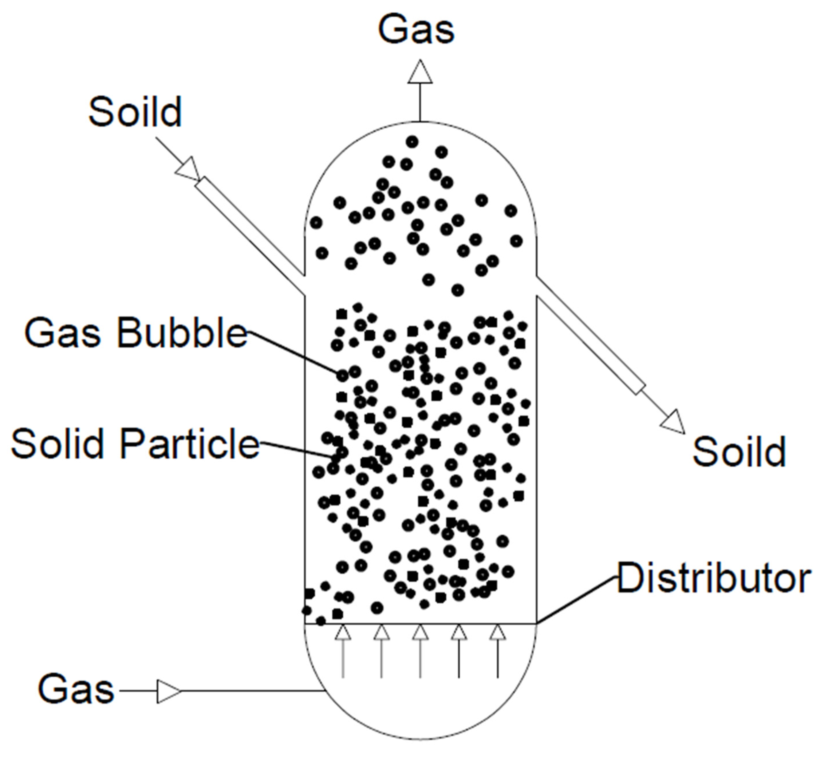
Among all the reactors used, this type allows for the highest conversion of synthesis gas to DME. M.E.E. Abashar [89] conducted studies in which tests were carried out with the use of three reactors: a fixed-bed reactor, a fluidised bed reactor, and a slurry reactor. The resulting CO conversion (Xco), selectivity of DME (XDME), and yield of DME (PDME) were compared. Those for a slurry reactor were 17%, 70%, and 0.2 g/g/h, respectively; those for a fixed-bed reactor were 10.7%, 91.9%, and 0.5 g/g/h, respectively; and those for a fluidised bed reactor were 48.5%, 97%, and 0.45g/g/h, respectively. It was shown that the highest results were obtained for the fluidised bed reactor (see Figure 10). Moreover, they possess several advantages: (a) good mixing, which allows isothermal and temperature control to be achieved; (b) low pressure drop; (c) slight diffusion limitation due to the use of fine particles; (d) a slight pressure drop; (e) the possibility of using a large amount of catalyst; and (f) easy circulation of the catalyst to be regenerated [89].
The disadvantage of this reactor is the tendency to lose the catalyst due to collision with the inner walls of the reactor. DME synthesis in this type of reactor is not a very popular solution, as evidenced by the few literature reports. However, it is an interesting alternative to direct fixed-bed DME synthesis [89,90,91].
- (c)
- Isothermal adiabatic reactor
An isothermal adiabatic reactor (see Figure 11) is a type of fixed-bed reactor. This type of reactor is a combination of a heat exchanger and conventional reactor, in which the reactions take place on the tube wall and the heat of the reaction is dissipated by coolant on the shell side of the reactor. Comparing the conventional adiabatic reactor with the isothermal reactor, the isothermal reactor is more controlled and provides higher reaction efficiency [93].
- (d)
- Slurry reactors
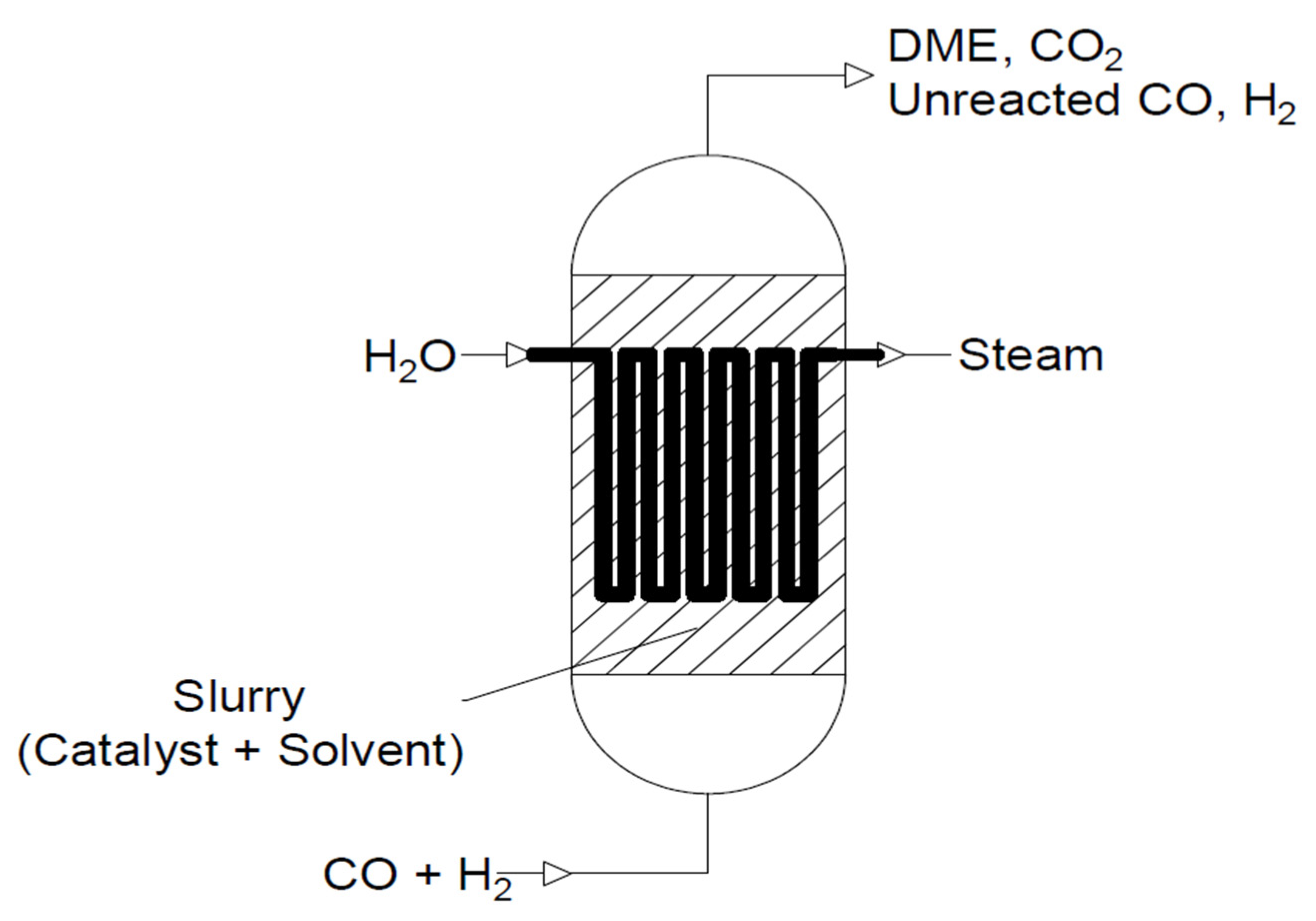
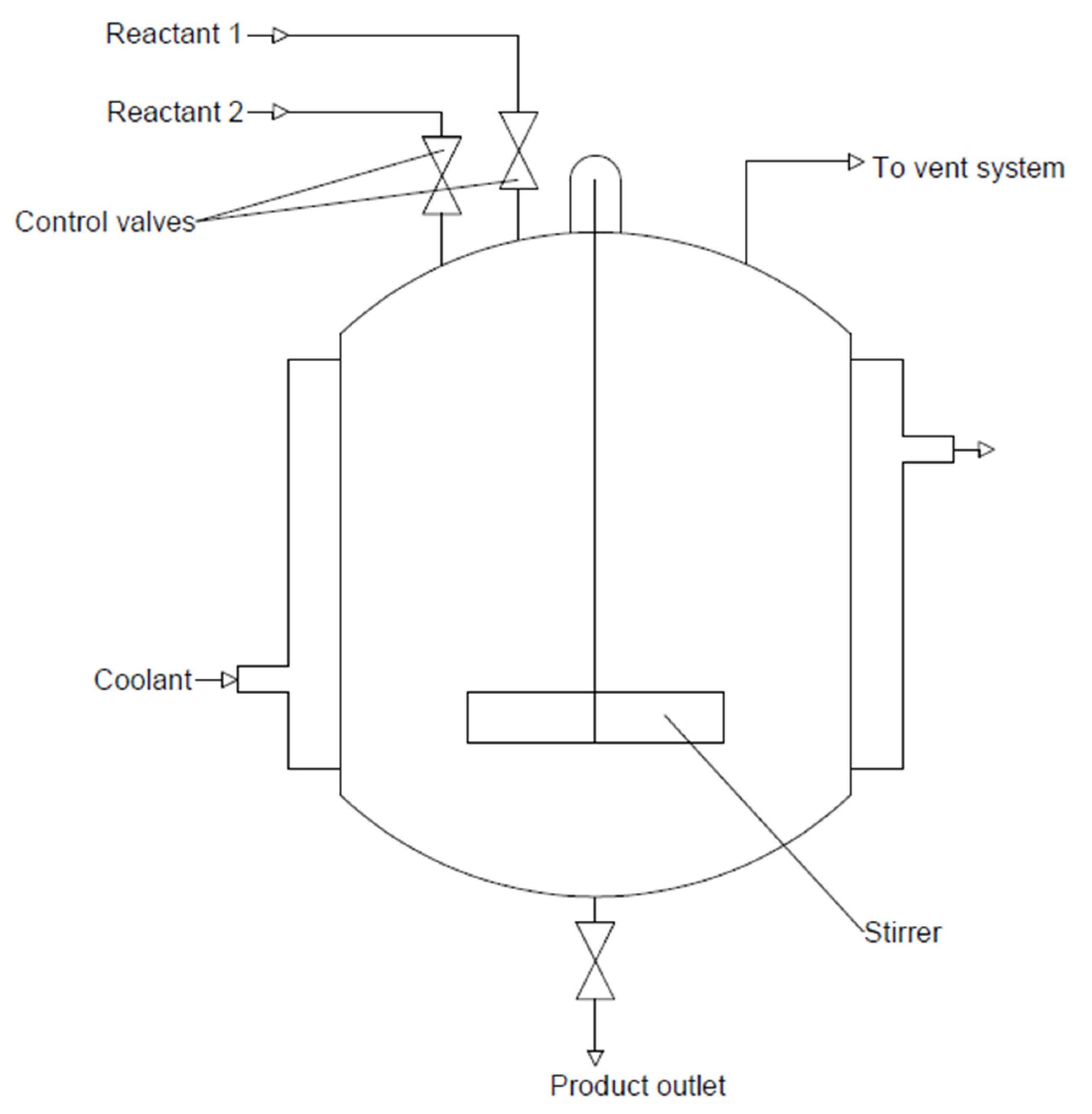
Another frequently used reactor is a slurry reactor (see Figure 12). The catalyst is suspended in inert solvent and comes into contact with the bubbling reactants. This allows for better control of the temperature distribution and pressure of the reaction, making it more efficient. The transfer of bulk particles is much slower than that in fixed-bed reactors. The catalyst in this type of reactor is less prone to deactivation, although losses may occur during the reaction. However, the disadvantage of this reactor is the need to use complicated equipment [94,95]. Among the most-used solvents, paraffin [19,96,97,98] white mineral oil (Witco 70) [96,98,99], or white mineral oil (Sontex 100) [5] may be distinguished. A schematic diagram of a slurry reactor is shown below.
6. Reasons for Catalysts Deactivation—Fixed Bed and Slurry Reactors
The issue of the deactivation of the catalyst for DME synthesis, despite many efforts to modify and improve stability, is still one of the main challenges. Depending on the type of catalyst, the addition of promoters, such as MgO, ZnO, ZrO2, Ca, Co, Fe, Ca, Ce, and Ni, and the chosen synthesis route (co-precipitation, physical mixing, sol-gel, adsorption, ion exchange, and impregnation), the degree of deactivation varies. Moreover, the type of deactivation also depends on the configuration of the reactor. In the subsections below, sources and reasons for catalyst deactivation are presented for the two most widely used reactor systems: fixed-bed and slurry reactors.
- (A)
- Fixed-bed reactors
In Table 1, selected catalysts, process parameters of DME synthesis, and reasons for deactivation are presented. A fixed-bed reactor system is the most often used on a laboratory scale or in pilot plants due to the low production costs and simplicity [100]. In this type of reactor, the diffusion limitations are eliminated through gas–solid contact. Moreover, the use of this type of reactor allows the application of an optimal longitudinal temperature profile from the inlet to the outlet of the reactor. This means that the reaction rate is high near the inlet, and, by lowering the temperature, high outlet conversion is achieved. However, the presence of endothermic and exothermic reactions may result in a drop in efficiency and the sintering of the catalyst. The greatest risk is the formation of so-called hot spots inside the reactor, which cause local overheating and are a direct cause of catalyst sintering. Studies have shown that the thermal sintering process, in the case of a copper-based catalyst, is kinetically slow and hardly reversible or completely irreversible; however, it can be prevented by controlling the process temperature. Consequently, a high synthesis gas recycling rate is required to avoid temperature rises, with consequent lower conversion and ultimately high operating costs [1,100]. An alternative to synthesis gas comprising H2 and CO is the use of CO2 instead of CO. In this case, an additional reaction takes place—the water gas shift reaction to hydrogenate CO2. This step is critical to the process that takes place, as it affects the rate of methanol formation and dehydration, which is associated with the formation of water [101].
Concerning the metallic part of the DME synthesis catalysts, Cu oxidation and ZnO agglomeration were identified as the important triggers of deactivation. The structures of ZnO and Cu should be stabilised to improve the catalyst’s lifetime during hydrogenation to methanol. The addition of a hydrophobic promoter can stabilise the above compounds and inhibit the oxidation of metallic copper [80]. It should also be considered that the addition of a promoter may negatively affect the catalytic activity. Research by H. Bahruji et al. confirmed that some metal additives block active acid sites. The addition of TiO2 to catalysts consisting of PdZn and the acid part of H-ZSM-5 and γ-Al2O3 causes a decrease in the yield due to the blocking of Bronsted acid sites [102].
Another factor favouring the deactivation of the catalyst is the formation of carbonaceous residues and their deposition on the surface or in the pores of the catalyst, thus covering the active sites. These residues are widely known as coke, which includes polycyclic aromatic hydrocarbons. A small part of the volatile compounds trapped in the catalyst pores is considered as the precursor, and not the actual coke. D. Zapater et al. [88] conducted tests on methanol dehydration to DME using the SAPO-34 catalyst and SAPO-34 combined with bentonite and aluminium with a mass ratio of 50/30/20. It was found that the SAPO-34 zeolite was rapidly inactivated by the gradual conversion of the active hydrocarbon’s intermediates into less-active polycyclic aromatics and ultimately into coke. Moreover, deactivation is caused by the blocking of the pores, making the desorption process more complex. Low acidity increases the initial concentration of acid sites and ultimately increases the reaction rate. The results show that, at the beginning of the process, volatile compounds are formed, the amount of which stabilises with constant concentration. In the case of sites with high acidity, compounds with higher acidity are initially formed, which increase the rate of the reaction.
Among the factors causing the deactivation of the exchange catalyst is also the influence of the side reactions of water. The released water promotes the deactivation of the acid part of the catalyst, thus leading to the formation of carbon deposits. X. Fan et al. conducted an experiment comparing the effectiveness of CuO/ZnO/Al2O3 (CZA) and CuO/ZnO/Al2O3/ZrO2 (CZZA) at an atomic ratio of 4:2:1:0.5 by the co-precipitation method. They used CZA and CZZA as the metallic parts and H-ZSM-5 as the acid part for DME synthesis from CO2 and H2. Although γ-Al2O3 achieves high DME selectivity, it tends to absorb water, which contributes directly to the deactivation of the catalyst. In contrast, H-ZSM-5 exhibits higher resistance to adsorption and has strong acid sites (Lewis and Bronsted), offering high activity in terms of MeOH conversion at a relatively low reaction temperature (220–260 °C) [103].
Kim et al. [104] performed the synthesis of dimethyl ether through the dehydration of methanol over a modified H-ZSM-5. The H-ZSM-5 catalyst was modified with a potassium compound using potassium nitrate at a K/Al ratio of 0.6. The reaction temperature ranged from 190 to 400 °C. The catalytic activity varied linearly with the reaction pressure. As the flow rate of the feed gas stream increased, the methanol conversion decreased under low temperatures. Moreover, a decrease in conversion was observed at temperatures below 250 °C. Catalyst deactivation is caused by the formation of coke or dealumination, which causes the gradual disintegration of the crystal structure. The reaction mechanism is mainly based on the interaction between methanol molecules adsorbed on acid Lewis sites with an alcoholate anion adsorbed on an adjacent basic site. Generally, the stronger the acid centres, the more active the catalysts are; however, in the case of Bronsted centres, their strength and reaction temperature must be controlled to avoid the formation of hydrocarbons. As already mentioned, a balance between acidity and hydrophobicity is needed to achieve optimal activity during methanol dehydration.
N. Mota et al. [25] discussed Ren et al.’s results about the deactivation of a CZZA/ZSM-5 catalyst. It has been proven that catalysts can lose their activity due to interactions between the metal and acid sites, for example, during ion exchange between the hydrogenation and dehydrogenation catalysts. In addition, a significant decrease in the specific surface area and an increase in coke amount were observed after 100 h of the process. The presence of zeolite was found to have an adverse effect on the stability of the catalyst. The results suggest that zeolite-induced coking may be responsible for the deactivation of the catalyst. Methane and coke were also formed as by-products during DME dehydration. The formation of methane is due to the strong binding of methoxylates on acid sites, leading to the formation of surface structures that lead to decomposition to form CO, H2, and CH4. A regeneration trial of the Cu-Fe2O4/γ-Al2O3 catalyst in an air atmosphere for 2 h at 600 °C was also carried out.

Table 1.
Deactivation of the catalyst in a fixed-bed reactor system.
| Catalyst | Ratio of Reagents | P (MPa) | T (°C) | Conclusions Regarding Deactivation | Ref. |
|---|---|---|---|---|---|
| CZA/γ-Al2O3 | CO:H2 = 1:1 | 40 | 245 | Catalyst deactivation strongly depends on the pressure and temperature of the process. | [105] |
| CZA/H-ZSM-5, core-shell structure SiO2/Al2O3 = 20.5–50.0 | CO2/H2 = 1:3 | 3.0 | 270 | Formation of coke was observed on the acid surface of the catalyst. | [77] |
| CZA/mesoporous alumina | H2/CO/CO2 = 50/10/40 | 50.0 | 275 | At 275 °C, the DME yield was 55%. The deactivation of the catalyst during the dehydration of methanol is influenced by water, which causes the catalyst to sinter. The problem with deactivation starts above 300 °C. | [106] |
| 5% Pd, 15% Zn/TiO2 and H-ZSM-5, SiO2/Al2O3 = 30, and γ-Al2O3 | CO2:H2:N2 = 1:3:1 | 2.0 | 270 | Temperatures above 270 °C caused the formation of oxygenates. The efficiency of PdZn/H-ZSM-5 catalysts is much higher compared to that of PdZn/TiO2-H-ZSM-5, which is mainly caused by the blocking of the main Bronsted acid sites. | [102] |
| CZA (20–40 mesh), commercial | H2/CO2 = 3 | 3.0 | 200 | The deactivation was caused by changes in the structure of ZnO and by the sintering of copper particles. | [80] |
| CZA/H-ZSM-5, 3:1 mass ratio, CZZA-HZSM-5, 1:1 mass ratio | H2:CO2 = 3:1 | 3.0 | 220–260 | In the case of the CZA/H-ZSM-5 catalyst, after 100 h, the CO2 conversion dropped from 26.8% to 24.0%, and the DME selectivity dropped from 17.5% to 14.3%. During the CZZA/H-ZSM-5 experiment, the methanol conversion dropped slightly from 20.9% to 20.4%, and the DME yield dropped from 13.0% to 12.2%. The main cause of catalyst deactivation was water, which affected coke formation on the H-ZSM5 surface due to the high methanol content of the CZZA layer | [103] |
| CZA/HSM-5, 52–65% CuO, 20–30% ZnO and 8–10% Al2O3. H-ZSM-5, and SiO2/Al2O3 = 40 | H2:CO = 1:1 | 3.0 | 230 | Two methods of catalyst reduction were used in this process. The difference was the reduction temperature. In method 1, it was 230 °C, and in method 2, it was 170 °C. In addition, in method 1, reduction was used for H2, and in the case of method 2, the catalyst was reduced with a mixture of H2/N2. The deactivation was associated with the sintering of copper particles and coking of the acid part. It has been shown that reduction with pure hydrogen causes faster catalyst deactivation due to temperature changes during the copper ions’ reduction, leading to sintering and, thus, the formation of larger Cu clusters. | [107] |
| CZA = 6:3:1, γ-Al2O3, NH4ZSM-5 SiO2/Al2O3 = 80, NH4ZSM-5 SiO2/Al2O3 = 23, HZSM-5 SiO2/Al2O3 = 80, HZSM-5 SiO2/Al2O3 = 23 10% Ag-γ-Al2O3, and η-Al2O3 CZA/ZSM-5 | H2:CO = 2:1, and 1–4% of CO2 | 2 | 200–260 | The deactivation of the catalyst was due to coke, which was formed during methanol formation. Coke formation is attributed to the degradation of methoxy ions (very important for the dehydrogenating capacity of the metallic function, which will contribute to activating the condensation step) and the dehydrocyclisation and aromatic condensation steps. | [21] |
| 10% Ag-γ-Al2O3 and η-Al2O3 CZA/ZSM-5 | 0.1 | 180–300 | Deactivation of heterogeneous catalysts is the result of poisoning, vapour/solid reactions, solid/solid reactions, fouling, and vapour compound formation. The most dangerous and most common are poisoning, sintering, and fouling. | [108] | |
| CZA/ZSM-5 | H2/CO/CO2/N2 = 61/30/5/4 volume ratios | 40 | 320 | The reason for deactivation is both coke deposition in the active sites of the metallic and quasi-catalytic functions, and the second reason for deactivation is the sintering of the CZA catalyst at temperatures above 325 °C. The results indicate that the decrease in the activity of the catalyst is related to the coking of the catalyst, but, ultimately, the activity is not affected. | [61] |
- (B)
- Slurry phase reactors
The second-most-applied reactor for DME synthesis is the slurry reactor. Often, this type of reactor is used for commercial purposes. The slurry reactor system is often called a three-phase system, since the gas reactants come into contact with solid particles suspended in an intermedium. Due to the better heat transfer and lower capital expenditure in comparison with other solutions, slurry reactors are mostly used on an industrial scale. Compared with fixed-bed reactors, the temperature control in slurry reactors is much simpler due to the large heat capacity of the solvent. Nevertheless, the use of this reactor has some disadvantages, such as the complicated equipment necessary for the proper operation of the reactor and the loss of catalyst particles during the process [35,94,95,109,110]. The main advantage of using a slurry reactor includes the even temperature distribution inside the reactor, which allows for sintering avoidance, and the reduction of energy requirements. Moreover, the simple method for the catalyst dosing and separation process additionally is in favour for this solution. The catalyst particles are introduced by dispersing them in an inert solvent inside the reactor. However, the lack of wettability of the catalyst due to the hydrophilic surface and the hydrophobic nature of the organic solvent may lead to the formation of aggregates and abnormal distributions. The operation life of the DME catalyst in industrial applications is 4 to 8 years [111,112]. It is limited by catalyst deactivation, which is caused by poisoning and thermal sintering. According to the research carried out by Dieterich et al., a decrease in the catalyst activity is observed from 14 to 21% during the first 1000 h of the process. Thereafter, deactivation slows down to about 2% per 1000 h for 3 years. At the end of the catalyst’s life, its activity decreases by 20% [112].
Similar to fixed-bed systems, the coking of the catalyst is one of the most prevalent inactivation factors. In Table 2, selected data on the different types of catalysts and the different conditions of the processes carried out in the slurry reactor with particular emphasis on the problem of catalyst deactivation in each of the slurry phase processes are presented. Coke formation is a complex process and arises in many successive stages. Among the most critical steps are the intermolecular condensation reaction of the reactants and/or products and the intramolecular condensation (cyclisation) reaction [113]. The most typical coke hydrocarbons include alkenes, dienes, and polyaromatic compounds. Short-molecule alkenes and dienes on acid zeolites quickly undergo condensation reactions. This leads to the formation of polar and heavy products that can be easily trapped on the zeolite’s surface. Polyaromatic molecules are less reactive compared with alkenes and dienes. However, due to their higher polarity and volume, these are compounds that are retained more strongly on acidic zeolites. Their contact time with acid sites is much longer, which forces them to transform into heavier molecules that no longer desorb from the zeolite.
Coke can be classed as light or heavy. A light coke burns at a temperature of 300–500 °C. It consists mainly of volatile and low-condensing aromatic hydrocarbons. A heavy coke burns at temperatures above 500 °C. It consists of much more complex polyaromatic compounds [6,7,8]. Coke is formed through a condensation reaction, but also hydrogen transfer and dehydration. The resulting coke is composed of stable polyaromatic compounds. For coke formation on the surface of the catalyst, not only are chemical reactions required in or inside its pores, but coke retention may also be due to spherical blockage, strong chemisorption at active sites and its entrapment in pores, low solubility, and low volatility. These dependencies can occur in combination, as well as independently. The retention of coke on the catalyst’s surface is usually associated with its low solubility or volatility. The coke is deposited on both the outer and inner surfaces of the catalyst. In the case of zeolites, light coke usually deposits in the pores of the zeolite, and heavy coke mainly deposits on its external surface [112]. Upon the inactivation of H-ZSM-5, the samples change from white to yellow–brown, suggesting the formation of highly unsaturated organic substances at around 300 °C. However, during methanol conversion at a temperature of about 450 °C, the deactivated catalyst turns black, which proves the formation of coke. In slurry reactors, the coke is lighter and consists of xylenes and trimethylbenzenes, in opposition to C4-C6-substituted benzenes. In both slurry reactors and fixed-bed reactors, the localisation of coke occurs primarily in the microporous channels of the zeolite (>60%). In the synthesis of dimethyl ether in slurry reactors, the catalyst activity is related to the blocking of the catalysts’ pores by products originating from the thermal decomposition of the dispersion medium [76]. An important aspect is the selection of an appropriate catalyst for the reactions taking place. The following conditions determine the formation of coke:
- (a)
- Reaction characteristics—the type and speed of major and side transformations, the shape and size of reactants and products, and reactor type;
- (b)
- Catalyst features—type, number, location, and strength of active sites, and size and shape of pores and holes;
- (c)
- Process conditions—temperature and pressure [112].
According to [5,25,114], the second of the key factors that lead to catalyst deactivation is water, which is formed in the methanol dehydration process and becomes trapped in the system due to the resistance created by the slurry. The loss of activity is mainly caused by the deactivation of the methanol synthesis catalyst. Thus, under the influence of water, the morphology of the catalyst changes. Cuo transforms into Cu2(OH)2CO3, ZnO transforms into Zn5(OH)6(CO3)2, and the synergistic effect between these oxides is diminished. Studies have shown that use of the γ-Al2O3 catalyst in the synthesis of dimethyl ether allows achieving high selectivity [25,64,115]. However, the γ-Al2O3 catalyst is not recommended for this type of process, especially with CO2, because it strongly absorbs water, leading to the catalyst’s deactivation. According to B. P. Karaman and N. Oktar [116] the use of this catalyst as a methanol-dehydrating part results in the rapid deactivation of the catalyst due to strong adsorption on the Lewis acid sites. Lewis acid sites have also been shown to lead to coke formation during methanol dehydration. Coke may be deposited on the catalyst’s surface due to the occurrence of the Boudouard or the methane cracking reactions, as shown in reactions (11) and (12), respectively. More hydrophobic materials, such as zeolites, e.g., H-ZSM-5 catalysts, are not sensitive to water; thus, such catalysts are deactivated by covering acid sites or blocking the pores by the adsorption and deposition of carbon compounds in the channels.
2CO ↔ C + CO2 ΔH°(298) = −172.4 kJ/mol
CH4 ↔ C + 2H2, ΔH°(298) = 74.8 kJ/mol
The deactivation of the catalyst is influenced not only by the process parameters, but also by the method of synthesis and by various types of metal additives. Y. Tan et al. investigated the effect of manganese on the final DME yield. For the tests, they used CZA and CZAMn catalysts, as well as MnCuZnAl. The catalysts were then physically mixed 2:1 with γ-Al2O3. In the case of the CZAMn catalyst prepared by the co-precipitation method, it was found that CuO could be easily reduced, and the reduced Cu was well dispersed. The opposite effect was obtained for the MnCuZnAl catalyst, which was prepared by impregnation. It has been found that a higher Al/Zn ratio allows for a higher DME yield [117]. It has been shown that, during the catalytic process, the crystallite sizes of copper and zinc oxide significantly increase because of copper recrystallisation, despite the better heat exchange in the slurry reactor. The transformation of Cu2O to CuO leads to a loss of catalyst activity [118].
Moreover, deactivation is also caused by compounds containing sulfur, chlorine, iron, nickel, arsenic, and carbonyls, which are the cause of the loss of activity. However, sulfur tolerance is higher compared with that of chloride because it is scavenged by zinc oxide from the Cu/ZnO catalyst. In addition, the formation of carbonyls and arsenic is favoured by a high concentration of carbon monoxide, which results from the use of unsuitable steel grades [119]. It is recommended to use carbonyl traps containing lead oxide due to the formation of iron and nickel carbonyls that may theoretically form inside pipes, reactors, and steel gas cylinders in contact with synthesis gas, if their surface is not covered with aluminium [56,120].
S. Papari et al [95] conducted an experiment in a slurry reactor using a CZA/γ-Al2O3 catalyst. Liquid paraffin was used as a solvent. A H2/CO substrate ratio of 3/1 was used. It was found that the deactivation was caused by coke and water formation. Specific information is provided in the table below.
The results presented by H. Zhang, W. Li, and W. Xiao showed that the deactivation of the catalyst occurred faster in the slurry than in the fixed-bed reactor. The preparation of the CZA/HZSM-5 (SiO2:Al2O3 = 40) catalyst before the process involves physical mixing and crushing up to 10 μm particle sizes for both slurry and fixed-bed reactor systems. It was shown that the rate of catalyst deactivation was influenced by the formed water and methanol, the concentration of which was much higher in the fixed bed compared with the slurry system. In method 1, CZA/HZSM5 was further pressed using a tablet-pressing machine, crushed, and sieved to obtain the fraction in the range of 20–40 mesh. It was observed that, after the DME synthesis process, each catalyst particle caused both methanol and dehydration synthesis. In method 2, each of the components of CZA/HZSM-5 were pressed into tablet form, crushed, and sieved with 20–40-mesh and 40–60-mesh-number sieves, and then physically blended. In method 2, the methanol synthesis and methanol dehydration were separated by sieving [107].
Table 2.
Deactivation of the catalysts in slurry reactors.
| Catalyst | Type of Solvent | Ratio of Gases | Type of Reactor | P (MPa) | T (°C) | Results and Discussion | Ref. |
|---|---|---|---|---|---|---|---|
| CZA-γ-Al2O3 | Liquid paraffin | H2:CO:CO2 = 68%:28%:3% | Stainless-steel high-pressure reactor, inside diameter of 16 mm, and total length of 400 mm | 5.0 | 260 | Methanol synthesis catalyst (MSC) deactivated more rapidly in the slurry reactor compared with the fixed-bed reactor. The released water was the direct cause of MSC catalyst deactivation. In the slurry reactor, the solvent created additional resistance for water removal from the reaction system. | [82] |
| Mg/ZSM-5, Si/Al = 30 | Polydimethylsiloxane and silicone oil (syltherm 800), | [-] | Fixed-bed: catalyst (0.4 mm-0.6 mm fraction)/inert quartz at a ratio of 1:1, 1 g of catalyst, and slurry reactor | 1.0 | 320 | Results from two reactors were presented: fixed-bed and slurry reactor. Coke formation was slower in the slurry reactor and amounted to 1.4 mg, compared with 1.7 mg in the fixed-bed reactor. On the external catalyst surface, the weight fraction of coke was higher, at about 11%. | [94] |
| CZA/HZSM-5, Si/Al = 40 | Solvent: inert liquid medium | H2:CO = 1:1 | Fixed-bed microreactor, i.d. 10 mm, length 300 mm, and 2 g of catalyst, and slurry reactor | 3.0 | 260 | The catalyst was prepared in two different ways. Methanol penetrated much faster from the metal surface of the catalyst to the acid part. Likewise, water was consumed much faster in the water–gas shift reaction. The contact area for the second method was much smaller; therefore, the diffusion of methanol and water on the catalyst’s surface became more difficult. The deactivation of the catalyst in this process was mainly due to the sintering of copper particles. | [107] |
| Commercial H-MFI, SiO2/Al2O3 = 80 | Solvent: oils, such as a Downtherm RP hydrocarbon oil, PMS-1000, Syltherm 800 silicone oils, and pentaerythritol ester | Slurry reactor, volume 250 mL | 0.1 | 260–280 | Commercial catalyst (H-MFI) was modified with magnesium, lanthanum, zirconium, and zinc. It was found that, at temperatures above 300 °C, the dispersion liquids decomposed significantly to form light hydrocarbons. It was confirmed that the decomposition of silicone oils, especially Syltherm 800, was much lower than those of hydrocarbon oils or pentaerythritol ester. The highest degree of DME conversion was achieved using Syltherm 800 solvent. About 90% DME conversion was obtained. Inert gas (to 10–20%) to avoid rapid deactivation of catalyst was used. The influence of different solvents on the DME synthesis process was studied. The reasons for deactivation were the formation of side reactions, C1–C4 reactions especially, and the presence of water and liquid organic products. | [94] | |
| CZA, CZAMn, and MnCZA | Liquid paraffin | H2/CO = 2.1 | Slurry reactor | 5.0 | 260 | The gas molar ratio H2/CO of 2.1 proved that the addition of manganese had a positive effect on the stability of the catalyst, but only in the case of the CZAMn catalyst synthesised by the co-precipitation method. Additionally, it prevented the quick sintering of the catalyst. Ultimately, 76.5% CO conversion and 66.7% selectivity for DME were achieved. | [117] |
| CZA | Liquid paraffin | CO:H2 = 1:2 | Slurry reactor | 5.0 | 200–300 | The temperature above the Tammann point (<190) was believed to be responsible for the deactivation of the copper-containing catalysts. It was found that the CZA catalyst retained its selectivity at the level of 75–80% at the temperature of 300 °C. The declining CO conversion was due to the accumulation of water in the reaction zone. This decomposed the zinc oxide and deactivated the catalyst. | [118] |
| CZA/Al2O3 | Liquid paraffin | H2:CO = 3:1 | Slurry reactor | 5.0 | 270 | Deactivation of catalysts was faster at higher pressures. The less water, the longer the life of the bifunctional catalyst. It was found that, if the amount of water exceeded 0.16 mol.% in the feed, then this factor played a negative role in the DME yield and the catalyst’s life was shortened. | [121] |
7. Strategies for Catalyst Regeneration
According to deactivation and regeneration, it is suggested that high-tech system reactors should be designed to prevent the loss of catalyst activity and achieve high activity and yield. With these solutions, we can manipulate the catalyst, method of synthesis, and parameters, and change the parameters of the process. It is an interesting alternative for this synthesis.
- II.
- High-Tech Systems
- (a)
- Double-reactor system
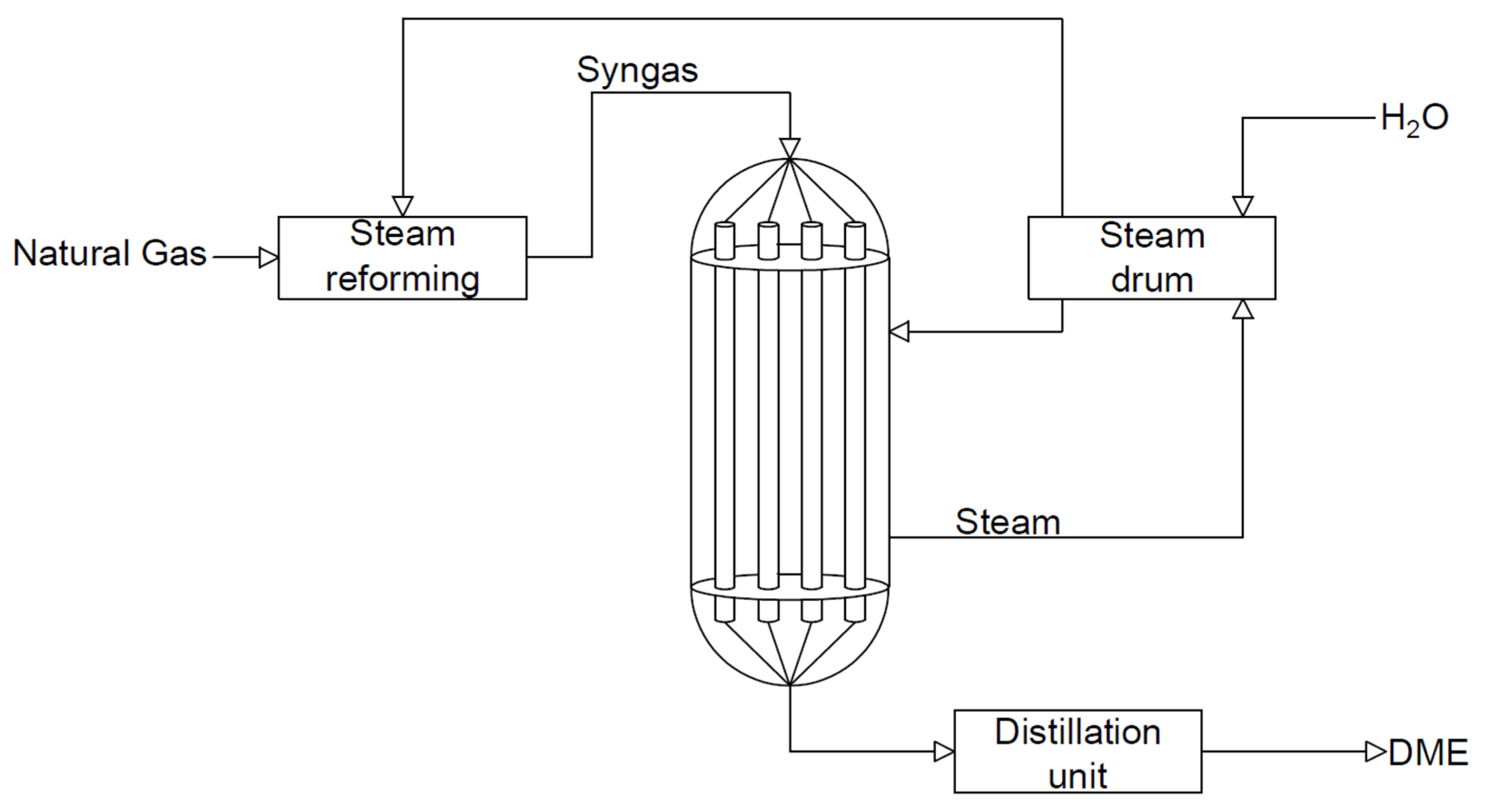
In this type of reactor system, the heat is provided by exothermic reactions. In the first reactor, the cold stream is preheated by the flowing gases. The water in the first reactor is heated by the heat generated by the exothermic reactions and is then forced into the second reactor (see Figure 13). This solution allows the production of about 60 tons /day of DME. This solution allows the reduction of production costs due to the recovery of heat [1,122,123].
- (b)
- Tubular membrane reactors
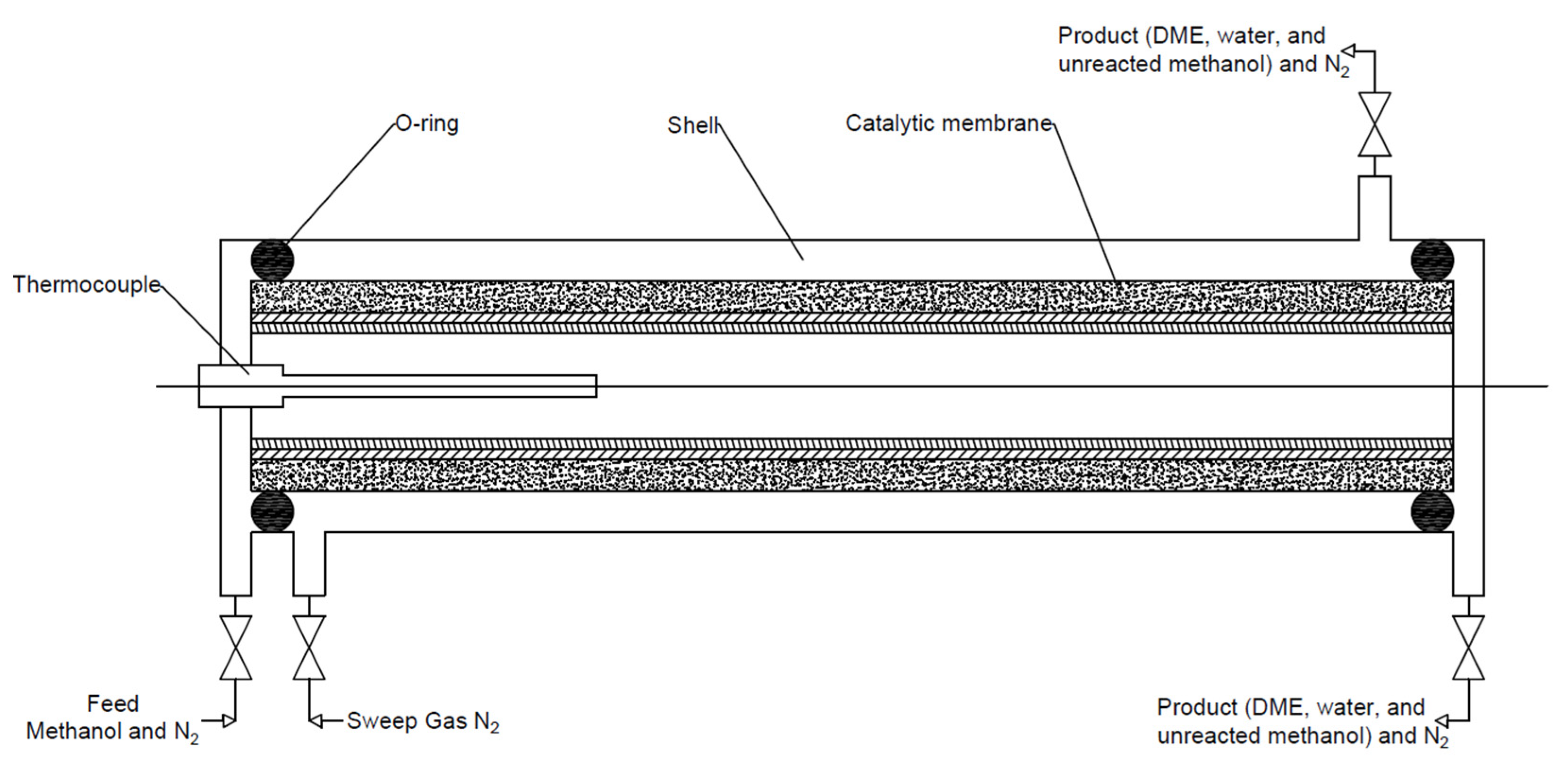
The purpose of the membrane used in DME reactor systems is to separate the produced water vapour from the reaction slurry. As a result, the resulting water does not deactivate the catalyst, especially the acid part. The membrane can be made of metal, ceramic–metal composite, or ceramic [124]. Currently, the most widely used membranes are amorphous silica, F-4SF, ZSM-5, MOR, SIL, and polymer membranes. However, due to pore-clogging, and thermal and mechanical instability, there is a need to test more preferred materials as membranes for this type of reactor. The removal of the in situ water leads to an improvement in the DME yield and improves the process stability compared with a conventionally packaged bed. This type of reactor (see Figure 14) consists of two coaxial tubes: an inner tubular membrane and an outer shell of the reactor in which the catalyst bed is located. In the case of exothermic reactions, there is a co-current circulation of the reaction mixture and the coolant to avoid overheating [1,86,125].
- (c)
- Microstructural reactors
Microstructural reactors (see Figure 15) are reactors in which the reaction takes place in channels or fractures with a sub-millimetre range. They provide a high surface-area-to-volume ratio and a short distance to the wall, which significantly improves heat and mass transfer. They are suitable for both exothermic and endothermic reactions. These types of reactors allow for full control over the process conditions, which allows avoiding the problem of local overheating, with thermal instability, and allows maintaining laminar flow, appropriate compactness, and parallel processability [1,126,127].
- (d)
- Catalytic distillation
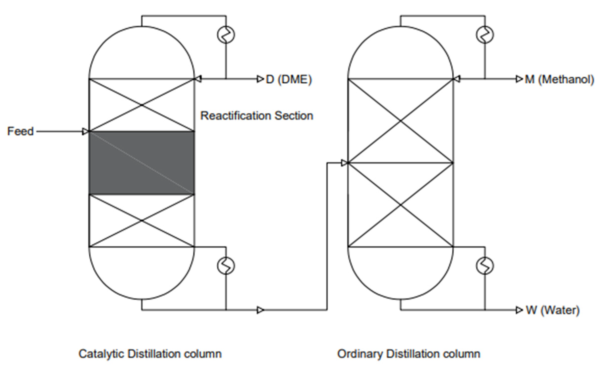
This system consists of two distillation columns (see Figure 16). This system allows ultra-pure DME to be obtained. Reactive distillation (RD) is a process in which reactions and a product separation process are combined. It is also known as catalytic distillation (CD) when a solid reactor is used. Studies have shown that the most economically viable reactions are equilibrium-limited reactions with methanol dehydration. They also allow for greater process intensification and are energy-efficient in terms of cost. A single CD tower allows for the replacement of the dehydration reactor and distillation column in conventional DME synthesis processes. The catalytic distillation conditions are mild, as a temperature range of 40–180 °C and pressures of 0.80–1.2 MPa are used. The mechanism of methanol dehydration itself is very simple. The boiling point of methanol is between the boiling points of water and DME. The design pressure in the methanol distillation tower is low due to the large boiling point difference between water and DME. Water and DME can be drawn from the bottom and top of the CD tower, respectively. DME can also be obtained by using alternative DME synthesis technology. Among others, simultaneous synthesis and separation can be achieved in a thermally coupled distillation column and a separation baffle column (DWC), which replaces the direct distillation sequence. This solution saves energy by 12–58% and reduces CO2 emissions by about 60%; the operating costs alone are reduced by about 30% [101,128].
- (e)
- Reactor with a spherical membrane
Spherical reactors can replace conventional fixed-bed reactors (see Figure 17). This type of solution was developed due to the undesirable pressure drops, high reactor manufacturing costs, poor diffusion through the catalyst bed, water generation, and low efficiency in tubular reactors. Two types of reactors are proposed: the radial bed flow reactor (RF-SPR) and the axial bed flow reactor (AF-PSR). The AF-PSR is superior and more efficient compared with the RF-SPR. The AF-SMR reactor consists of two spheres, and the inner part is covered with a water-permeable selective membrane. Methanol is introduced axially into the inner zone through a packed bed. Water vapour is passed through the H-SOD membrane and is then removed by the sweep gas [93].
- (f)
- Temperature-gradient reactor
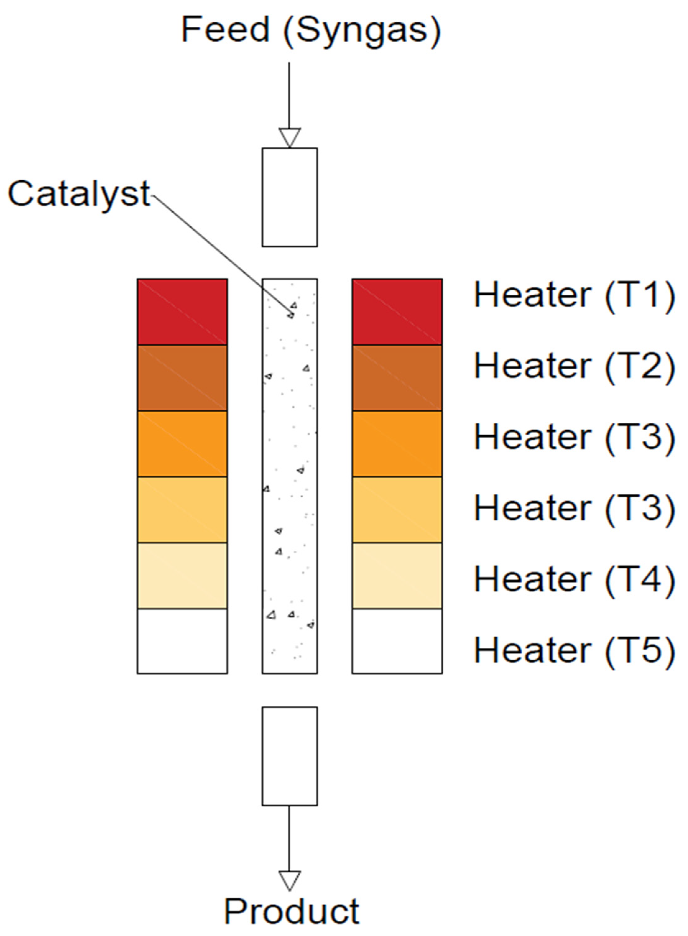
In this type of reactor (see Figure 18), the bed temperature gradually decreases along the length of the reactor as the reaction gas mixture flows downwards. The catalyst bed is divided into five zones, and all zones are optimised to achieve the highest possible syngas conversion. To improve CO conversion at lower pressures (<3 MPa), the reactor temperature needs to be optimised accordingly using an artificial neural network (ANN) and a genetic algorithm (GA). These five zones are coded as ‘genes’, and their suitability is determined by the CO conversion obtained depending on a given temperature and a given ‘gene’ [101,129,130].
In industry, when the catalyst activity decreases, it is common practice to:
- (1)
- Restore the activity of the catalyst;
- (2)
- Use the catalyst for another process;
- (3)
- Recover and recycle the important and/or expensive catalytic components;
- (4)
- Remove the catalyst.
For economic reasons, regeneration and reuse are the most preferred. Catalyst removal is usually a last resort due to environmental reasons. A typical 500 MW coal-fired power plant can save between $500,000 and $1,000,000 per year. Research shows that the service life of the catalyst after its regeneration should be the same as that at the beginning [103]. However, the regeneration of catalysts has rarely been described in the literature.
Susceptibility to regeneration is one of the most important properties of catalysts. Table 3 presents a list of selected catalysts, process parameters, and applied regeneration methods reported in the literature. In the case of metallic part deactivation mainly due to copper particles’ sintering, no regeneration treatment may be applied to restore the appropriate size and level of the Cu particles dispersion. The regeneration of the metallic part of the bifunctional catalysts for DME synthesis would require the dissolution of the catalyst and its further reconstruction using selected preparation methods. In the case of dehydration, part-regeneration may be achieved via the removal of deposited coke. As presented by Cordero-Lanzac T. [40] and others, two steps of catalyst regeneration may be distinguished. In the first step, the catalyst is subjected to annealing at 550 °C for 2 h under nitrogen flow, and in the second step, the coke is combusted in the air flow with a temperature increase of 5 °C/minute from 350 to 550 °C. The combustion of coke allows for the full regeneration of the catalyst. It is very important to age the coke. This is crucial for industrial-scale regeneration processes [55]. High-temperature annealing under an inert and/or air atmosphere is the most appropriate for the dehydration part of the DME catalyst. The residual compounds will be decomposed at temperatures below 400 °C. Such treatment allows recovering up to 90% of the initial activity of the catalyst. T. Cordero-Lanzac [40] described regeneration using a flow of nitrogen and air. Initially, the catalyst was regenerated in a nitrogen flow at 350 or 400 °C for 10 min and then at 550 °C in an air flow for 5 min. The air regeneration temperature was similar to the calcination temperature of the catalyst. Although complete coke deposition is observed at 550 °C, this does not mean the complete recovery of catalytic activity. Therefore, two regeneration cycles were carried out. The first regeneration was carried out using nitrogen at 550 degrees for 2 h or burning coke with a temperature rise from 350 to 550 °C. Clear effects of the catalyst acidity and reaction conditions on the amount and composition of the coke formed were observed. An increase in the temperature and/or catalyst acidity favours coke deposition, which is explained by the higher activity of acid sites in secondary reactions. The slight development of coke structures is explained by its complete combustion during the temperature build-up from 350 to 550 °C. The catalyst completely recovers its activity, which enables its use on an industrial scale.
Y. Luan et al. [131] conducted an experiment using CuOZnOAl2O3/γ-Al2O3-HZSM-5 catalyst in a fixed-bed reactor. This catalyst was then regenerated using three mixtures—5%O2-He, 5%CO2-He, and 5%N2O-He—for 2 h. The results showed that the best mixture for catalyst regeneration was 5%O2-He. In addition, this mixture allowed for the redispersion of the copper particles, which was impossible with the other two mixtures. Furthermore, the turnover frequency (TOF) value was kept constant at around ), and in the case of N2O and CO2 regeneration, the copper particles were not redispersed, and the catalytic activity was slightly improved. An increase in TOF indicates that a change in the nature of the acid sites may occur after regeneration.
I. Sierra et al. [55] carried out an experiment with CZA/γ-Al2O3 catalysts in a fixed-bed reactor with different process parameters. They carried out the process at 250, 275, 325, and 375 °C under pressures of 2.0, 3.0, and 4.0 MPa at H2/CO molar ratios of 2/1, 3/1, and 4/1. Different molar ratios of water to syngas were used, i.e., 0.08 and 0.2. The total amounts of coke were 4.1 wt.% and 1.2 wt.%, respectively, due to the amount of water present in the reaction system. The regeneration was carried out as follows: initially, the sample was flushed with a helium stream to remove air from the system, and then flushed with a helium stream at 300 °C for 30 min; the next step was to lower the temperature to 150 °C and regeneration with a He–O2 mixture of 50% for 30 min. The treatment prior to burning the coke is of particular importance, as this is intended to age the coke by unifying its structure. The fraction of coke that requires a higher temperature, between 330 and 380 °C, settles on the y-Al2O3 no-bearer and its combustion is not catalysed. It has been confirmed that the combustion of coke deposited on the metal can start at temperatures above 150 °C. The phenomenon of coke heterogeneity has been observed in acidic catalysts with a bi-modal pore structure, in which more eluted coke (with a lower H/C ratio) is generated in the mesopores, and its combustion is slower than that in less-eluted coke, i.e., more hydrogenated coke generated in the micropores. Temperature-programmed oxidation (TPO) is an effective tool for determining the morphology of coke, as well as its location in the catalyst. This heterogeneity of coke combustion is characteristic of the ageing stage and the use of coke combustion kinetics is of particular importance when designing industrial-scale regeneration.
A. T. Aguayo [132] carried out experiments with two catalysts—CZA/γ-Al2O3 and CZA/Na-HZSM-5—in a fixed-bed reactor. The regeneration of catalysts was studied using 10 reaction–regeneration cycles. The difficulty in the regeneration of catalysts is related to the acid part. Initially, the catalyst was flushed with helium at 260 °C. It was proven that CuO sintering occurs at 300 °C. Coke combustion was carried out in an air–helium mixture, where the helium content was gradually reduced to avoid the local sintering of the catalyst. After regeneration, it was found that the CZA/γ-Al2O3 catalyst did not regenerate and, consequently, the DME selectivity and yield decreased. As the amount of regeneration increased, the yield reached an equilibrium state, resulting in yield and selectivity that were half of those of the fresh catalyst. In contrast, the CZA/Na-HZSM-5 catalyst, after regeneration, regained its catalytic activity after 10 regeneration cycles, resulting in no contraindications for industrial use.
The method of the burning of coke should be carried out with special care due to the possibility of changes in the metallic part of the DME catalyst [103]. Although coke can be disposed of by burning at higher temperatures, the decrease in activity is irreversible in the temperature range from 250 to 350 °C due to the thermal sintering of copper leading to the irreversible loss of active surface. To avoid the sintering of copper articles, multiple cycles of treatment under oxidation at lower temperatures may be applied. X. Fan [103] presented two methods of catalyst regeneration with the use of air:
- (a)
- Heating at 250 °C for four cycles, with each cycle lasting 10 h;
- (b)
- Rinsing at three different temperatures of 250 °C, 300 °C, or 350 °C for three cycles.
Even though the lowering of the coke removal temperature results in the preservation of copper dispersion, the heavier compounds, such as oligomers and aromatics, cannot be removed. They accumulate in the catalyst structure and then agglomerate into larger and heavier compounds that are increasingly hard to remove at relatively low temperatures [4,103,133].
K.C. Liang et al. [134] conducted an experiment in which the ammonium form of the H-ZSM-5 catalyst was used. The experiment was carried out in a tubular reactor, and the tests were carried out for 240 h at a temperature of 300 °C. Regeneration was carried out with the use of air for 10 h, with flow of 0.5 l pm, pressure of 0.10 MPa, and temperature of 570 °C. The regeneration carried out in this way allowed the structure of the catalyst to remain unchanged after six regenerations. Moreover, it allowed the number of aromatics to be reduced from 56.6% vol. to 30.2 vol.%
M.A. Armenta et al. [81] conducted tests of methanol dehydration to dimethyl ether on the CuO/γ-Al2O3 catalyst. The reaction was carried out in a U-type tubular reactor at 0.1 MPa and a temperature of 290 °C. A process temperature above 300 °C causes the formation of by-products, such as CO2, CO, CH4, HCOOH, and many others, which contribute to the deactivation of the catalyst. Regeneration was carried out in flowing air for 2 h at a temperature of 600 °C. The MeOH conversion was 70%, and, after the regeneration process, was slightly reduced to 66%.
X. Fan carried out the experiment of CO2 hydrogenation to methanol and dimethyl ether with a CuO/ZnO/Al2O3/ZrO2/HZSM-5 catalyst. The process was carried out at 240 °C and a pressure of 2.8 MPa. The first regeneration was carried out at 250 °C in air flow. It was shown to recover most of the initial activity. The second regeneration allowed recovery of 93%. As the regeneration temperature increased, the percentage recovery decreased. For a temperature of 300 °C, the recovery was 88%, and for a temperature of 350 °C, the recovery was 83%. The decrease in activity after successive regeneration cycles is due to copper sintering under the higher temperature leading to the irreversible loss of the copper’s active surface. Although the coke can be disposed of by incineration, there is a partially irreversible loss of activity [103].
The main disadvantage of using air for regeneration is the formation and emission of carbon dioxide. It is particularly uneconomic, because the combustion of coke in the regeneration of spent catalysts accounts for almost half of the CO2 emitted to the atmosphere. Therefore, the gasification method is an alternative to air combustion. For the gasification process, steam (Equation (14)) or carbon dioxide (IV) (Equation (13)) may be used. Due to the low reactivity of CO2 and the method requiring a high temperature (700–900 °C), the application of this method is limited to catalysts with high heat resistance. If these conditions are not met, the catalyst may suffer structural damage and sinter. On the other hand, the use of steam as a gasification agent allows for the direct production of synthesis gas (CO + H2) (Equation (14)) in the temperature range of 700 to 900 °C.
CO2 gasification C(s) + CO2(g) → 2CO(g), ΔH°(298) = +172.00 kJ/mol
Steam gasification C(s) + H2O(g) → CO(g) + H2(g), ΔH°(298) = +131.00 kJ/mol
Another method that allows the regeneration of the catalyst is hydrogenation, which is based on the reaction of coke with hydrogen or light carbon gases, such as alkanes (15). Walker et al. reported a low efficiency of regeneration by this method at a temperature of 800 °C (O2, H2O, and CO2), finding the lowest efficiency for regeneration with H2.
C(s) + 2H2(g) → CH4(g) ΔH°(298) = −74.00 kJ/mol
When regenerating the catalyst, it is recommended to additionally use an increased pressure of 0.10 to 1.0 MPa. The location and nature of the coke also have a strong influence on the hydrogenation of coke. In most cases, the coke is only partially removed; as the H/C ratio is increased, the coke is partially reacted to form lighter compounds. Studies have shown that coke is removed from the Brønsted acid sites on the inner surface of the catalyst, while the outer surface remains intact. Thus, the complete removal of the coke by hydrogenation is impossible, and the elevated operating conditions may degrade the catalyst [135].
Among the strategies to prolong catalysts’ service time, deposit prevention has also been reported in the literature. This is most often achieved by manipulating the structure and composition of the catalysts. Dealumination is one of the methods of zeolite modification, but also one of the causes of catalyst deactivation. It involves the partial removal of aluminium from the tetrahedral skeletal sites and them taking up an extra molar position. For this purpose, the zeolite is most often treated with steam, acids (organic and inorganic), chelating agents, such as H4EDTA, salts, or inorganic ligands, such as F-. Aluminium removal is also possible by using an additional silicon source, e.g., SiCl4 or (NH4)2SiF6 [111]. This causes some micropores to be partially converted into mesopores. Although the microporous structure favours the formation of small molecules, such as olefins, during methanol conversion, it does increase the formation of carbon deposits [136].
R. Liu et al. [77] used CZA nanoparticles with HZSM-5 membrane. HZSM-5 was synthesised by tetrapropyloammonium hydroxide as a templating agent. In this catalyst, CZA is used as the core and HZSM-5 as the shell. They carried out an experiment of DME synthesis from H2–CO2 mixtures in a fixed-bed reactor under 3.0 MPa pressure and a temperature of 270 °C. They used a volume ratio of substrates CO2/H2 of 1/3. They observed coke formation on the surface of the acid part, which was a reason for the catalyst’s deactivation. The methanol formed in the core can then pass through the zeolite shell to achieve sufficient contact with the active sites of the H-ZSM-5 shell to ultimately transform them into end-products. These factors make it possible to achieve higher availability of reagents to the active sites. The inner part of the core-shell structures is most likely free from thermal agglomeration, as it is insulated from other outer surfaces. Additionally, the H-ZSM-5 catalyst can be dispersed in voids and pores to prevent active site aggregation during catalyst calcination.
For the industrial conversion of methanol to DME, γ-Al2O3 catalysts have the highest efficiency. The modification of γ-Al2O3 by ZSM-5 may result in improved reactivity, resistance to deactivation, and hydrothermal stability. They also prepared ZSM-5/γ-Al2O3/LC formed by liquid-phase coating. The conversion of methanol was 91.9% and selectivity of DME was 100%. During the preparation of the liquid ZSM-5, the main problem was the desiliconisation and dealumination of part of the skeleton in ZSM-5 due to the change in the pH of the raw material. Moreover, the low charge density of ZSM-5 modified the surface charge properties of γ-Al2O3 and improved the hydrothermal properties of the composite catalyst [137].
To avoid deactivation by water, this catalyst should be appropriately modified, and its strongly hydrophilic properties should be influenced. Studies have shown that modifying this catalyst with metals, such as silver and copper, which act as electron acceptors, increases its activity and selectivity. The enhancement of the improvement in catalyst activity is associated with the improvement in Lewis acidity and improved surface properties by reducing hydrophilicity [58]. γ-Al2O3 and η-Al2O3 catalysts both have Lewis acid–base sites, mainly with weak and moderately strong acid centres, and Bronsted acid centres. Interest in them is still high due to their low price, high mechanical strength, large surface area, and excellent thermal stability [138]. In the case of a variety, η-Al2O3, research by A. I. Osman et al. showed that the addition of 10% Ag in the form of AgNO3 to the synthesis caused an increase in catalytic activity in the temperature range from 180 to 300 °C under atmospheric pressure. The same catalyst was also presented, but with different silver contents, namely 1% and 15%. The tests were performed in a fixed-bed reactor at WHSV = 48.4 h−1. Moreover, a higher degree of stability under steady-state conditions was found due to an increase in Lewis surface acidity and hydrophobicity. In conclusion, a balance between acidity and hydrophobicity is needed to achieve optimal activity during methanol dehydration. H. Jiang et al. [139] carried out the synthesis of γ-Al2O3 with the addition of copper at contents of 2%, 5%, 8%, and 15%. It was shown that the most optimal copper content in this catalyst was 5%. As a result of the research, the CO conversion was 72% and the DME selectivity was 69%. The experiment was carried out in a tubular reactor, where the catalyst content was 1 g, at a temperature of 310 °C and 5.0 MPa. The authors also suggested the use of the above catalyst with copper as a bifunctional catalyst for the synthesis of dimethyl ether.
Table 3.
Regeneration strategies of DME catalysts.
| Catalyst | Ratio of Gases | Type of Reactor | Pressure (MPa) | T (°C) | Results and Discussion | Ref. |
|---|---|---|---|---|---|---|
| NH4-ZSM-5 | [-] | Tubular reactor | 0.1 | 300 | Regeneration was carried out with the use of air for 10 h, with a flow of 0.5l pm, pressure of 0.10 MPa, and temperature of 570 °C. The regeneration carried out in this way allowed the structure of the catalyst to remain unchanged after six regenerations. Moreover, it allowed reducing the content of aromatics from 56.6% vol. to 30.2 vol.% | [134] |
| CuO/γ-Al2O3 modified with hematite | [-] | U-type tubular reactor | 0.1 | 290 | It was concluded that hematite addition caused a decrease in by-product formation when Cu:Fe = 1:1 Regeneration was carried out in air flow at 600 °C for 2 h. After regeneration, the maximum value of conversion was 66%, and that before was 70%. | [81] |
| HZSM-5, Si/Al = 15 and 140 | [-] | Fixed-bed reactor | 0.15 | 325–400 | Oligomerisation, condensation, and aromatisation pathways had high impacts on coke formation. Temperatures of 350–550 °C were best for totally removing coke structures. This is very useful for industries that carry out processes in reactions similar to the MTO process. | [40] |
| CZZA/HZSM-5, | H2:CO2 = 3:1 | Fixed-bed reactor | 2.8 | 240 | The best temperature for regeneration was 250 °C. Higher temperatures caused losses of copper activity and irreversible losses of the active surface of copper. Even though the lowering of the coke removal temperature resulted in the preservation of copper dispersion, heavier compounds, such as oligomers and aromatics, could not be removed. They accumulated in the catalyst structure and then agglomerated into larger and heavier compounds that were increasingly hard to remove at relatively low temperatures. | [103] |
| ZSM-5/γ-Al2O3 | [-] | Fixed-bed reactor | 0.1 | 280 | The water content of the raw methanol solution reached 20%. The deactivation rate of γ-Al2O3 was approximately 12.5 times higher than that of pure methanol. They also prepared ZSM-5/γ-Al2O3/LC by liquid-phase coating, and some of the skeleton incurred desiliconisation and dealumination in the raw materials. As a consequence, the acid strength was increased by modulating the Si/Al ratio of the ZSM-5 skeleton, and the mesoporous ratio of catalysts was improved. | [137] |
| CZA/γ-Al2O3 | H2:CO2 = 4:1 | Slurry reactor | 0.4 | 275 | The coke was burnt with air flow at a temperature below 325 °C. The main cause of deactivation was coke. The experiment showed that there was no sintering at temperatures below 325 °C. | [140] |
| Cu–Fe2O4/γ-Al2O3 | [-] | Fixed-bed reactor | 0.1 | 290 | This regeneration was carried out at 600 °C for 2 h in air. In this article, there was no information about the results of this regeneration. | [25] |
| HZSM-5, Si/Al = 140 | [-] | Fixed-bed reactor | [-] | [-] | Catalyst regeneration was carried out in 10 cycles. A clear effect of the catalyst acidity and reaction conditions on the amount and composition of the coke formed was observed. An increase in the temperature and/or catalyst acidity favoured coke deposition, which was explained by the higher activity of acid sites in secondary reactions. The slight development of coke structures was explained by their complete combustion during a temperature increase from 350 to 550 °C. The catalyst completely recovered its activity, which enabled its use on an industrial scale. | [40] |
| CZA/γ-Al2O3, CZA/Na-HZSM-5 | H2/CO = 4/1 | Fixed-bed reactor | 40 | 275 | After regeneration, it was found that the CZA/γ-Al2O3 catalyst did not regenerate; consequently, the DME selectivity and yield decreased. As the amount of regeneration increased, the yield reached an equilibrium state, resulting in yield and selectivity that were half of those of the fresh catalyst. | [132] |
| CZA/γ-Al2O3-H-ZS-5, | H2/CO = 2/1 | Fixed-bed reactor | 3.0 | 220 | The best regeneration results were obtained with a 5% O2–He mixture. This mixture allows for the redispersion of copper particles, which is impossible with the other two mixtures. From the experiments carried out, it was concluded that the deactivation of the catalyst was due to the sintering of the copper particles. It was found that the copper particles could be dispersed again. | [131] |
| CZA/γ-Al2O3 | H2/CO = 3/1 | Fixed-bed reactor | 0.3 | 275 | A temperature of 325 °C was the limiting condition to avoid irreversible deactivation by the sintering of the metallic part. Regeneration with a 5% O2/He mixture allowed the complete combustion of the coke. The treatment prior to burning the coke was of particular importance, as this was intended to age the coke by unifying its structure. The fraction of coke that required a higher temperature, between 330 and 380 °C, settled on the γ-Al2O3 no-bearer and its combustion was not catalysed. It was confirmed that the combustion of coke deposited on the metal could start at temperatures above 150 °C. The phenomenon of coke heterogeneity was observed in acidic catalysts with a bi-modal pore structure, in which more eluted coke (with a lower H/C ratio) was generated in the mesopores, and its combustion was slower than that in less-eluted coke, i.e., more hydrogenated coke was generated in the micropores. | [55] |
Summarising the table above, air or helium/air mixture is most often used for catalyst regeneration. The regeneration carried out with air or helium/air mixture allows the catalytic activity to be recovered. Furthermore, it has been confirmed that the use of a 5% O2/He mixture allows the re-dispersion of the copper particles, which is impossible with N2O or CO2 mixtures. Process temperatures higher than 300 °C are not recommended, as they result in the sintering of the copper particles, coke formation, and catalyst deactivation. The deactivation process is also affected by the presence of water. As shown in [55], the more water there is, the more coke there is in the sample. Additionally, the temperature of coke sparging should be chosen appropriately, because temperatures between 330 and 380 °C cause the combustion of larger coke fractions, but, at the same time, cause coke deposition on the γ-Al2O3 support and faster deactivation of the catalyst.
8. Conclusions and Outlook
Dimethyl ether (DME) is an alternative fuel. The high interest is due to its properties and high potential as a new-generation fuel. DME is an alternative to diesel, as an additive to LPG, or as an alternative to methane in gas turbines. However, the use of dimethyl ether and the complete replacement of another fuel with it is a very long process. It requires the construction of appropriate infrastructure, which is necessary for the supply of raw materials, and appropriate apparatus, and the development of the machine industry. The DME synthesis process requires the use of CO or CO2, greenhouse gases largely generated during the production of fossil fuels. Therefore, there is a need to reduce the formation of these gases; therefore a technology to limit their production should be developed.
The major problems that effectively hinder the effective preparation of dimethyl ether include the deactivation of the catalyst, the water produced, and the deposition of coke on the catalyst’s surface. The synthesis of DME from CO2 and H2 causes the formation of more water compared with the synthesis gas, which directly affects the faster deactivation of the catalyst and the results. This is due to the hydrophilicity of most catalysts. The final process efficiency is also influenced by the catalyst preparation method, its type, the process parameters, the type of reactor, and the gas ratios used during the process. In this case, further research is necessary, which will clearly indicate the appropriate parameters of DME synthesis. These should include high-performance catalytic systems, and the catalysts should be reusable, cost-effective, and highly water-resistant. Proper purification of the synthesis gas is also essential to prevent the poisoning of the catalyst during the synthesis of methanol. An important element that is often overlooked in the available literature is the problem related to the regeneration of catalysts. There is also a noticeable difference in the availability of literature on the reactors used. The most popular of these is the fixed-bed reactor. The second-most-used reactor is the slurry reactor. However, there is little actual literature describing both the slurry reactors and the deactivation and regeneration of the catalysts. There are still too few studies that have confirmed the effectiveness of the proposed solutions. Despite the attractiveness of dimethyl ether, it is necessary to intensify research and expand knowledge on the above-mentioned problems to finally obtain an economically attractive process that will allow reducing the use of fossil fuels and striving for an increasing number of green fuels.
Taking everything into account, we propose the following full-scale experiment procedure (see Figure 19) that should be followed by researchers who are planning to scale-up and commercialise their new ideas in DME catalyst development:
These basic steps are explained below. There are some, but unfortunately not many, researchers taking the next step after laboratory tests.
8.1. Preparation
- Preparation of a test system with strictly defined parameters—specified reactor and bed length;
- Optimisation of the operation of the system with a commercially available catalyst with known properties—achieve optimum conversion/selectivity.
8.2. Catalyst Development in Laboratory
- Modification of catalysts and testing on a test system;
- Selecting catalysts that are more advantageous than a commercial catalyst;
- Confirmation of the chosen catalysts in long-term tests (minimum 7 days);
- During research, a detailed analysis of the composition of the products and the analysis of the available technologies necessary for the separation of DME and the recycling of unreacted reagents should be carried out. Problems with the purification of the product stream may be crucial for the applicability of the technology.
8.3. Model Installation Designing
- (1)
- Preparation of a process design for a model installation, including flow calculations, mass and energy exchange, technological diagrams, and a list of apparatus and devices;
- (2)
- Designing the automation and analytics system for the model installation; Scale-up
- (3)
- Purchase, construction, and testing of a model installation on inert media—checking the tightness and stability of the system;
- (4)
- Testing the installation on a selected catalyst along with the possibility of purifying the product stream;
- (5)
- Confirmation of the catalyst’s improvement for DME synthesis and preliminary economic analysis of its introduction to the market.
Author Contributions
Conceptualization, J.S., I.W. and A.R.; methodology, J.S.; validation, I.W. and A.R.; formal analysis, I.W.; investigation, J.S. and S.M.; resources, I.W. and A.R.; data curation, J.S.; writing—original draft preparation, J.S. and S.M.; writing—review and editing, I.W. and A.R.; visualization, J.S. and S.M.; supervision, I.W. and A.R.; project administration, A.R.; funding acquisition, A.R. All authors have read and agreed to the published version of the manuscript.
Funding
This research was co-funded by the National Centre of Research and Development and PGNiG SA (Polskie Górnictwo Naftowe i Gazownictwo SA) in the EU Smart Growth Operational Programme, grant number POIR.04.01.01-00-0064/18-00.
Institutional Review Board Statement
Not applicable.
Informed Consent Statement
Not applicable.
Data Availability Statement
Not applicable.
Conflicts of Interest
The authors declare no conflict of interest.
References
- Azizi, Z.; Rezaeimanesh, M.; Tohidian, T.; Rahimpour, M.R. Dimethyl Ether: A Review of Technologies and Production Challenges. Chem. Eng. Process. Process Intensif. 2014, 82, 150–172. [Google Scholar] [CrossRef]
- Masudi, A.; Che Jusoh, N.W.; Muraza, O. Recent Progress on Low Rank Coal Conversion to Dimethyl Ether as Clean Fuel: A Critical Review. J. Clean. Prod. 2020, 277, 124024. [Google Scholar] [CrossRef]
- Sousa-Aguiar, E.F.; Appel, L.G.; Mota, C. Natural Gas Chemical Transformations: The Path to Refining in the Future. Catal. Today 2005, 101, 3–7. [Google Scholar] [CrossRef]
- Sun, J.; Yang, G.; Yoneyama, Y.; Tsubaki, N. Catalysis Chemistry of Dimethyl Ether Synthesis. ACS Catal. 2014, 4, 3346–3356. [Google Scholar] [CrossRef]
- Khadzhiev, S.N.; Ezhova, N.N.; Yashina, O.V. Catalysis in the Dispersed Phase: Slurry Technology in the Synthesis of Dimethyl Ether (Review). Pet. Chem. 2017, 57, 553–570. [Google Scholar] [CrossRef]
- Fei, J.; Hou, Z.; Zhu, B.; Lou, H.; Zheng, X. Synthesis of Dimethyl Ether (DME) on Modified HY Zeolite and Modified HY Zeolite-Supported Cu-Mn-Zn Catalysts. Appl. Catal. A Gen. 2006, 304, 49–54. [Google Scholar] [CrossRef]
- Ahmad, R.; Schrempp, D.; Behrens, S.; Sauer, J.; Döring, M.; Arnold, U. Zeolite-Based Bifunctional Catalysts for the Single Step Synthesis of Dimethyl Ether from CO-Rich Synthesis Gas. Fuel Process. Technol. 2014, 121, 38–46. [Google Scholar] [CrossRef]
- Laugel, G.; Nitsch, X.; Ocampo, F.; Louis, B. Methanol Dehydration into Dimethylether over ZSM-5 Type Zeolites: Raise in the Operational Temperature Range. Appl. Catal. A Gen. 2011, 402, 139–145. [Google Scholar] [CrossRef]
- Guisnet, M.; Magnoux, P. Coking and Deactivation of Zeolites Influence of the Pore Structure. Appl. Catal. 1989, 54, 1–27. [Google Scholar] [CrossRef]
- Moradi, G.R.; Ahmadpour, J.; Yaripour, F. Intrinsic Kinetics Study of LPDME Process from Syngas over Bi-Functional Catalyst. Chem. Eng. J. 2008, 144, 88–95. [Google Scholar] [CrossRef]
- Joelsson, J.M.; Gustavsson, L. Reductions in greenhouse gas emissions and oil use by DME (di-methyl ether) and FT (Fischer-Tropsch) diesel production in chemical pulp mills. Energy 2012, 39, 363–374. [Google Scholar] [CrossRef]
- Mao, D.; Xia, J.; Chen, Q.; Lu, G. Highly Effective Conversion of Syngas to Dimethyl Ether over the Hybrid Catalysts Containing High-Silica HMCM-22 Zeolites. Catal. Commun. 2009, 10, 620–624. [Google Scholar] [CrossRef]
- Li, T.; Wu, Q.; Wang, W.; Xiao, Y.P.; Liu, C.; Yang, F. Solid-Solid Reaction of CuFe2O4 with C in Chemical Looping System: A Comprehensive Study. Fuel 2020, 267, 117163. [Google Scholar] [CrossRef]
- Pinkaew, K.; Yang, G.; Vitidsant, T.; Jin, Y.; Zeng, C.; Yoneyama, Y.; Tsubaki, N. A New Core-Shell-like Capsule Catalyst with SAPO-46 Zeolite Shell Encapsulated Cr/ZnO for the Controlled Tandem Synthesis of Dimethyl Ether from Syngas. Fuel 2013, 111, 727–732. [Google Scholar] [CrossRef]
- Phienluphon, R.; Pinkaew, K.; Yang, G.; Li, J.; Wei, Q.; Yoneyama, Y.; Vitidsant, T.; Tsubaki, N. Designing Core (Cu/ZnO/Al2O3)-Shell (SAPO-11) Zeolite Capsule Catalyst with a Facile Physical Way for Dimethyl Ether Direct Synthesis from Syngas. Chem. Eng. J. 2015, 270, 605–611. [Google Scholar] [CrossRef]
- Grigor’eva, N.G.; Filippova, N.A.; Agliullin, M.R.; Kutepov, B.I.; Narender, N. Crystalline and amorphous aluminosilicates with different pore structures for the synthesis of pyridines. J. Chem. Res. 2017, 41, 253–261. [Google Scholar] [CrossRef]
- Maity, A.; Chaudhari, S.; Titman, J.J.; Polshettiwar, V. Catalytic Nanosponges of Acidic Aluminosilicates for Plastic Degradation and CO2 to Fuel Conversion. Nat. Commun. 2020, 11, 3828. [Google Scholar] [CrossRef]
- Zha, F.; Ding, J.; Chang, Y.; Ding, J.; Wang, J.; Ma, J. Cu-Zn-al Oxide Cores Packed by Metal-Doped Amorphous Silica-Alumina Membrane for Catalyzing the Hydrogenation of Carbon Dioxide to Dimethyl Ether. Ind. Eng. Chem. Res. 2012, 51, 345–352. [Google Scholar] [CrossRef]
- Palčić, A.; Jaén, S.N.; Wu, D.; Cai, M.; Liu, C.; Pidko, E.A.; Khodakov, A.Y.; Ordomsky, V.; Valtchev, V. Embryonic Zeolites for Highly Efficient Synthesis of Dimethyl Ether from Syngas. Microporous Mesoporous Mater. 2021, 322, 111138. [Google Scholar] [CrossRef]
- Bahadori, F.; Oshnuie, M.N. Exergy Analysis of Indirect Dimethyl Ether Production Process. Sustain. Energy Technol. Assess. 2019, 31, 142–145. [Google Scholar] [CrossRef]
- Abu-Dahrieh, J.; Rooney, D.; Goguet, A.; Saih, Y. Activity and Deactivation Studies for Direct Dimethyl Ether Synthesis Using CuO-ZnO-Al2O3 with NH4ZSM-5, HZSM-5 or γ-Al2O3. Chem. Eng. J. 2012, 203, 201–211. [Google Scholar] [CrossRef] [Green Version]
- Ogawa, T.; Inoue, N.; Shikada, T.; Ohno, Y. Direct Dimethyl Ether Synthesis. J. Nat. Gas Chem. 2003, 12, 219–227. [Google Scholar]
- Yagi, H.; Ohno, Y.; Inoue, N.; Okuyama, K.; Aoki, S. Slurry Phase Reactor Technology for DME Direct Synthesis. Int. J. Chem. React. Eng. 2010, 8. [Google Scholar] [CrossRef]
- Saravanan, K.; Ham, H.; Tsubaki, N.; Bae, J.W. Recent Progress for Direct Synthesis of Dimethyl Ether from Syngas on the Heterogeneous Bifunctional Hybrid Catalysts. Appl. Catal. B Environ. 2017, 217, 494–522. [Google Scholar] [CrossRef]
- Mota, N.; Ordoñez, E.M.; Pawelec, B.; Fierro, J.L.G.; Navarro, R.M. Direct Synthesis of Dimethyl Ether from Co2: Recent Advances in Bifunctional/Hybrid Catalytic Systems. Catalysts 2021, 11, 411. [Google Scholar] [CrossRef]
- Kunkes, E.L.; Studt, F.; Abild-Pedersen, F.; Schlögl, R.; Behrens, M. Hydrogenation of CO2 to Methanol and CO on Cu/ZnO/Al2O3: Is There a Common Intermediate or Not? J. Catal. 2015, 328, 43–48. [Google Scholar] [CrossRef] [Green Version]
- Vargheese, V.; Kobayashi, Y.; Oyama, S.T. The Direct Partial Oxidation of Methane to Dimethyl Ether over Pt/Y2O3 Catalysts Using an NO/O2 Shuttle. Angew. Chem. Int. Ed. 2020, 59, 16644–16650. [Google Scholar] [CrossRef]
- Vargheese, V.; Murakami, J.; Bando, K.K.; Tyrone Ghampson, I.; Yun, G.N.; Kobayashi, Y.; Ted Oyama, S. The Direct Molecular Oxygen Partial Oxidation of CH4 to Dimethyl Ether without Methanol Formation over a Pt/Y2O3 Catalyst Using an NO/NO2 Oxygen Atom Shuttle. J. Catal. 2020, 389, 352–365. [Google Scholar] [CrossRef]
- Atkins, M.P.; Earle, M.J.; Seddon, K.R.; Swadźba-Kwaśny, M.; Vanoye, L. Selective Homogeneous Synthesis of Dimethyl Ether from Methanol. Chem. Commun. 2010, 46, 1745–1747. [Google Scholar] [CrossRef]
- Grzybowska-Świerkosz, B. Elementy Katalizy Heterogenicznej; Wydawnictwo Naukowe PWN: Warszawa, Poland, 1993; pp. 45–48, 163–166. ISBN 83-01-10511-9. [Google Scholar]
- Wen, Z.; Wang, C.; Wei, J.; Sun, J.; Guo, L.; Ge, Q.; Xu, H. Isoparaffin-Rich Gasoline Synthesis from DME over Ni-Modified HZSM-5. Catal. Sci. Technol. 2016, 6, 8089–8097. [Google Scholar] [CrossRef]
- Xu, M.; Lunsford, J.H.; Goodman, D.W.; Bhattacharyya, A. Synthesis of Dimethyl Ether (DME) from Methanol over Solid-Acid Catalysts; Elsevier: Amsterdam, The Netherlands, 1997; Volume 149. [Google Scholar]
- Liuzzi, D.; Peinado, C.; Peña, M.A.; van Kampen, J.; Boon, J.; Rojas, S. Increasing Dimethyl Ether Production from Biomass-Derived Syngas: Via Sorption Enhanced Dimethyl Ether Synthesis. Sustain. Energy Fuels 2020, 4, 5674–5681. [Google Scholar] [CrossRef]
- Khandan, N.; Kazemeini, M.; Aghaziarati, M. Determining an Optimum Catalyst for Liquid-Phase Dehydration of Methanol to Dimethyl Ether. Appl. Catal. A Gen. 2008, 349, 6–12. [Google Scholar] [CrossRef]
- Samimi, F.; Bayat, M.; Rahimpour, M.R.; Keshavarz, P. Mathematical Modeling and Optimization of DME Synthesis in Two Spherical Reactors Connected in Series. J. Nat. Gas Sci. Eng. 2014, 17, 33–41. [Google Scholar] [CrossRef]
- Long, X.; Song, Y.H.; Liu, Z.T.; Liu, Z.W. Insights into the Long-Term Stability of the Magnesia Modified H-ZSM-5 as an Efficient Solid Acid for Steam Reforming of Dimethyl Ether. Int. J. Hydrogen Energy 2019, 44, 21481–21494. [Google Scholar] [CrossRef]
- Li, H.; He, S.; Ma, K.; Wu, Q.; Jiao, Q.; Sun, K. Micro-Mesoporous Composite Molecular Sieves H-ZSM-5/MCM-41 for Methanol Dehydration to Dimethyl Ether: Effect of SiO2/Al2O3ratio in H-ZSM-5. Appl. Catal. A Gen. 2013, 450, 152–159. [Google Scholar] [CrossRef]
- Alharbi, W.; Kozhevnikova, E.F.; Kozhevnikov, I.v. Dehydration of Methanol to Dimethyl Ether over Heteropoly Acid Catalysts: The Relationship between Reaction Rate and Catalyst Acid Strength. ACS Catal. 2015, 5, 7186–7193. [Google Scholar] [CrossRef]
- Budiman, A.; Ridwan, M.; Min, S.; Choi, J.; Won, C.; Ha, J.; Jin, D.; Suh, Y. Applied Catalysis A: General Design and Preparation of High-Surface-Area Cu/ZnO/Al2O3 Catalysts Using a Modified Co-Precipitation Method for the Water-Gas Shift Reaction. Appl. Catal. A Gen. 2013, 462–463, 220–226. [Google Scholar] [CrossRef]
- Cordero-Lanzac, T.; Ateka, A.; Pérez-Uriarte, P.; Castaño, P.; Aguayo, A.T.; Bilbao, J. Insight into the Deactivation and Regeneration of HZSM-5 Zeolite Catalysts in the Conversion of Dimethyl Ether to Olefins. Ind. Eng. Chem. Res. 2018, 57, 13689–13702. [Google Scholar] [CrossRef]
- Wang, L.; Huang, L.; Liang, F.; Liu, S.; Wang, Y.; Zhang, H. Preparation, Characterization and Catalytic Performance of Single-Atom Catalysts. Chin. J. Catal. 2017, 38, 1528–1539. [Google Scholar] [CrossRef]
- An, W.; Chuang, K.T.; Sanger, A.R. Dehydration of Methanol to Dimethyl Ether by Catalytic Distillation. Can. J. Chem. Eng. 2004, 82, 948–955. [Google Scholar] [CrossRef]
- Tokay, K.C.; Dogu, T.; Dogu, G. Dimethyl Ether Synthesis over Alumina Based Catalysts. Chem. Eng. J. 2012, 184, 278–285. [Google Scholar] [CrossRef]
- Velázquez-Herrera, F.D.; Fetter, G.; Rosato, V.; Pereyra, A.M.; Basaldella, E.I. Effect of Structure, Morphology and Chemical Composition of Zn-Al, Mg/Zn-Al and Cu/Zn-Al Hydrotalcites on Their Antifungal Activity against A. Niger. J. Environ. Chem. Eng. 2018, 6, 3376–3383. [Google Scholar] [CrossRef]
- Previtali, D.; Longhi, M.; Galli, F.; di Michele, A.; Manenti, F.; Signoretto, M.; Menegazzo, F.; Pirola, C. Low Pressure Conversion of CO2 to Methanol over Cu/Zn/Al Catalysts. The Effect of Mg, Ca and Sr as Basic Promoters. Fuel 2020, 274, 117804. [Google Scholar] [CrossRef]
- Sun, M.; Yu, L.; Ye, F.; Diao, G.; Yu, Q.; Hao, Z.; Zheng, Y.; Yuan, L. Transition Metal Doped Cryptomelane-Type Manganese Oxide for Low-Temperature Catalytic Combustion of Dimethyl Ether. Chem. Eng. J. 2013, 220, 320–327. [Google Scholar] [CrossRef]
- Kosova, N.I.; Vodorezova, O.Y.; Kurzina, I.A.; Kurina, L.N.; Vorobeva, V.M.; Shtertser, N.V.; Godymchuk, A.Y. The Catalysts Synthesis Methanol for Direct Synthesis of Dimethyl Ether from Synthesis Gas. Adv. Mater. Res. 2015, 1085, 29–33. [Google Scholar] [CrossRef]
- Fan, X.; Jin, B.; Ren, S.; Li, S.; Yu, M.; Liang, X. Roles of Interaction between Components in CZZA/HZSM-5 Catalyst for Dimethyl Ether Synthesis via CO2 Hydrogenation. AIChE J. 2021, 67, e17353. [Google Scholar] [CrossRef]
- Fan, X.; Ren, S.; Jin, B.; Li, S.; Yu, M.; Liang, X. Enhanced Stability of Fe-Modified CuO-ZnO-ZrO2-Al2O3/HZSM-5 Bifunctional Catalysts for Dimethyl Ether Synthesis from CO2 Hydrogenation. Chin. J. Chem. Eng. 2021, 38, 106–113. [Google Scholar] [CrossRef]
- Venugopal, A.; Palgunadi, J.; Deog, J.K.; Joo, O.S.; Shin, C.H. Dimethyl Ether Synthesis on the Admixed Catalysts of Cu-Zn-Al-M (M = Ga, La, Y, Zr) and γ-Al2O3: The Role of Modifier. J. Mol. Catal. A Chem. 2009, 302, 20–27. [Google Scholar] [CrossRef]
- Zuo, H.; Mao, D.; Guo, X.; Yu, J. Highly Efficient Synthesis of Dimethyl Ether Directly from Biomass-Derived Gas over Li-Modified Cu-ZnO-Al2O3/HZSM-5 Hybrid Catalyst. Renew. Energy 2018, 116, 38–47. [Google Scholar] [CrossRef]
- Hua, Y.; Guo, X.; Mao, D.; Lu, G.; Rempel, G.L.; Ng, F.T.T. Single-Step Synthesis of Dimethyl Ether from Biomass-Derived Syngas over CuO-ZnO-MOx (M = Zr, Al, Cr, Ti)/HZSM-5 Hybrid Catalyst: Effects of MOx. Appl. Catal. A Gen. 2017, 540, 68–74. [Google Scholar] [CrossRef]
- Ren, S.; Fan, X.; Shang, Z.; Shoemaker, W.R.; Ma, L.; Wu, T.; Li, S.; Klinghoffer, N.B.; Yu, M.; Liang, X. Enhanced Catalytic Performance of Zr Modified CuO/ZnO/Al2O3 Catalyst for Methanol and DME Synthesis via CO2 Hydrogenation. J. CO2 Util. 2020, 36, 82–95. [Google Scholar] [CrossRef]
- Zhang, Y.; Li, D.; Zhang, S.; Wang, K.; Wu, J. CO2 Hydrogenation to Dimethyl Ether over CuO-ZnO-Al2O3/HZSM-5 Prepared by Combustion Route. RSC Adv. 2014, 4, 16391–16396. [Google Scholar] [CrossRef]
- Sierra, I.; Ereña, J.; Aguayo, A.T.; Arandes, J.M.; Bilbao, J. Regeneration of CuO-ZnO-Al2O3/γ-Al2O3 catalyst in the Direct Synthesis of Dimethyl Ether. Appl. Catal. B Environ. 2010, 94, 108–116. [Google Scholar] [CrossRef]
- Ereña, J.; Sierra, I.; Olazar, M.; Gayubo, A.G.; Aguayo, A.T. Deactivation of a CuO-ZnO-Al2O3/γ-Al2O3 Catalyst in the Synthesis of Dimethyl Ether. Ind. Eng. Chem. Res. 2008, 47, 2238–2247. [Google Scholar] [CrossRef]
- Aguayo, T.; Ereña, J.; Mier, D.; Arandes, M.; Olazar, M.; Bilbao, J. Kinetic Modeling of Dimethyl Ether Synthesis in a Single Step on a CuO-ZnO-Al2O3/Gamma-Al2O3 Catalyst. Industrial 2007, 46, 5522–5530. [Google Scholar] [CrossRef]
- Wang, L.; Wu, W.T.; Chen, T.; Chen, Q.; He, M.Y. Ion-Exchange Resin-Catalyzed Synthesis of Polyoxymethylene Dimethyl Ethers: A Practical and Environmentally Friendly Way to Diesel Additive. Chem. Eng. Commun. 2014, 201, 709–717. [Google Scholar] [CrossRef]
- Wang, W.; Gao, X.; Yang, Q.; Wang, X.; Song, F.; Zhang, Q.; Han, Y.; Tan, Y. Vanadium Oxide Modified H-Beta Zeolite for the Synthesis of Polyoxymethylene Dimethyl Ethers from Dimethyl Ether Direct Oxidation. Fuel 2019, 238, 289–297. [Google Scholar] [CrossRef]
- Haltenort, P.; Hackbarth, K.; Oestreich, D.; Lautenschütz, L.; Arnold, U.; Sauer, J. Heterogeneously Catalyzed Synthesis of Oxymethylene Dimethyl Ethers (OME) from Dimethyl Ether and Trioxane. Catal. Commun. 2018, 109, 80–84. [Google Scholar] [CrossRef]
- Chen, W.H.; Lin, B.J.; Lee, H.M.; Huang, M.H. One-Step Synthesis of Dimethyl Ether from the Gas Mixture Containing CO2 with High Space Velocity. Appl. Energy 2012, 98, 92–101. [Google Scholar] [CrossRef]
- Kornas, A.; Śliwa, M.; Ruggiero-Mikołajczyk, M.; Samson, K.; Podobiński, J.; Karcz, R.; Duraczyńska, D.; Rutkowska-Zbik, D.; Grabowski, R. Direct Hydrogenation of CO2 to Dimethyl Ether (DME) over Hybrid Catalysts Containing CuO/ZrO2 as a Metallic Function and Heteropolyacids as an Acidic Function. React. Kinet. Mech. Catal. 2020, 130, 179–194. [Google Scholar] [CrossRef] [Green Version]
- Song, F.; Tan, Y.; Xie, H.; Zhang, Q.; Han, Y. Direct Synthesis of Dimethyl Ether from Biomass-Derived Syngas over Cu-ZnO-Al2O3-ZrO2(x)/γ-Al2O3bifunctional Catalysts: Effect of Zr-Loading. Fuel Process. Technol. 2014, 126, 88–94. [Google Scholar] [CrossRef]
- Liu, D.; Yao, C.; Zhang, J.; Fang, D.; Chen, D. Catalytic Dehydration of Methanol to Dimethyl Ether over Modified γ-Al2O3 catalyst. Fuel 2011, 90, 1738–1742. [Google Scholar] [CrossRef]
- Nie, R.; Lei, H.; Pan, S.; Wang, L.; Fei, J.; Hou, Z. Core-Shell Structured CuO-ZnO@H-ZSM-5 Catalysts for CO Hydrogenation to Dimethyl Ether. Fuel 2012, 96, 419–425. [Google Scholar] [CrossRef]
- Wei, Y.; de Jongh, P.E.; Bonati, M.L.M.; Law, D.J.; Sunley, G.J.; de Jong, K.P. Enhanced Catalytic Performance of Zeolite ZSM-5 for Conversion of Methanol to Dimethyl Ether by Combining Alkaline Treatment and Partial Activation. Appl. Catal. A Gen. 2015, 504, 211–219. [Google Scholar] [CrossRef]
- Aboul-Fotouh, S.M.K.; Aboul-Gheit, N.A.K.; Naghmash, M.A. Dimethylether Production on Zeolite Catalysts Activated by Cl-, F- and/or Ultrasonication. Ranliao Huaxue Xuebao/J. Fuel Chem. Technol. 2016, 44, 428–436. [Google Scholar] [CrossRef]
- Kianfar, E.; Salimi, M.; Pirouzfar, V.; Koohestani, B. Synthesis and Modification of Zeolite ZSM-5 Catalyst with Solutions of Calcium Carbonate (CaCO3) and Sodium Carbonate (Na2CO3) for Methanol to Gasoline Conversion. Int. J. Chem. React. Eng. 2018, 16, 1–7. [Google Scholar] [CrossRef]
- Bakare, I.A.; Muraza, O.; Sanhoob, M.A.; Miyake, K.; Hirota, Y.; Yamani, Z.H.; Nishiyama, N. Dimethyl Ether-to-Olefins over Aluminum Rich ZSM-5: The Role of Ca and La as Modifiers. Fuel 2018, 211, 18–26. [Google Scholar] [CrossRef]
- Magomedova, M.; Galanova, E.; Davidov, I.; Afokin, M.; Maximov, A. Dimethyl Ether to Olefins over Modified Zsm-5 Based Catalysts Stabilized by Hydrothermal Treatment. Catalysts 2019, 9, 485. [Google Scholar] [CrossRef] [Green Version]
- Sheng, H.; Ma, H.; Qian, W.; Fei, N.; Zhang, H.; Ying, W. Platinum-Copper Bimetallic-Modified Nanoprism Mordenite for Carbonylation of Dimethyl Ether. Energy Fuels 2019, 33, 10159–10166. [Google Scholar] [CrossRef]
- Wang, Q.; Han, W.; Lyu, J.; Zhang, Q.; Guo, L.; Li, X. In Situ Encapsulation of Platinum Clusters within H-ZSM-5 Zeolite for Highly Stable Benzene Methylation Catalysis. Catal. Sci. Technol. 2017, 7, 6140–6150. [Google Scholar] [CrossRef]
- Golubev, K.B.; Zhang, K.; Su, X.; Kolesnichenko, N.V.; Wu, W. Dimethyl Ether Aromatization over Nanosized Zeolites: Effect of Preparation Method and Zinc Modification on Catalyst Performance. Catal. Commun. 2021, 149, 106176. [Google Scholar] [CrossRef]
- Pedram, M.Z.; Kazemeini, M.; Fattahi, M.; Amjadian, A. A Physicochemical Evaluation of Modified HZSM-5 Catalyst Utilized for Production of Dimethyl Ether from Methanol. Pet. Sci. Technol. 2014, 32, 904–911. [Google Scholar] [CrossRef]
- Pekmezci Karaman, B.; Oktar, N.; Doğu, G.; Doğu, T. Bifunctional Silicotungstic Acid and Tungstophosphoric Acid Impregnated Cu–Zn–Al & Cu–Zn–Zr Catalysts for Dimethyl Ether Synthesis from Syngas. Catal. Lett. 2020, 150, 2744–2761. [Google Scholar] [CrossRef]
- Obukhova, T.; Stashenko, A.N.; Batova, T.I.; Kolesnichenko, N.V. Dimethyl Ether Conversion to Light Olefins in Slurry and Fixed-Bed Reactors: Coke Nature and Location on Mg/ZSM-5 Catalyst. J. Chem. Technol. Biotechnol. 2021, 96, 2696–2703. [Google Scholar] [CrossRef]
- Liu, R.; Tian, H.; Yang, A.; Zha, F.; Ding, J.; Chang, Y. Preparation of HZSM-5 Membrane Packed CuO-ZnO-Al2O3 Nanoparticles for Catalysing Carbon Dioxide Hydrogenation to Dimethyl Ether. Appl. Surf. Sci. 2015, 345, 1–9. [Google Scholar] [CrossRef]
- Witoon, T.; Numpilai, T.; Dolsiririttigul, N.; Chanlek, N.; Poo-arporn, Y.; Cheng, C.K.; Ayodele, B.V.; Chareonpanich, M.; Limtrakul, J. Enhanced Activity and Stability of SO42−/ZrO2 by Addition of Cu Combined with CuZnOZrO2 for Direct Synthesis of Dimethyl Ether from CO2 Hydrogenation. Int. J. Hydrogen Energy 2022. [Google Scholar] [CrossRef]
- Chiang, C.L.; Lin, K.S. Preparation and Characterization of CuO–Al2O3 Catalyst for Dimethyl Ether Production via Methanol Dehydration. Int. J. Hydrogen Energy 2017, 42, 23526–23538. [Google Scholar] [CrossRef]
- Liang, B.; Ma, J.; Su, X.; Yang, C.; Duan, H.; Zhou, H.; Deng, S.; Li, L.; Huang, Y. Investigation on Deactivation of Cu/ZnO/Al2O3 Catalyst for CO2 Hydrogenation to Methanol. Ind. Eng. Chem. Res. 2019, 58, 9030–9037. [Google Scholar] [CrossRef] [Green Version]
- Armenta, M.A.; Valdez, R.; Quintana, J.M.; Silva-Rodrigo, R.; Cota, L.; Olivas, A. Highly Selective CuO/Γ–Al2O3 Catalyst Promoted with Hematite for Efficient Methanol Dehydration to Dimethyl Ether. Int. J. Hydrogen Energy 2018, 43, 6551–6560. [Google Scholar] [CrossRef]
- Wang, D.S.; Tan, Y.S.; Han, Y.Z.; Noritatsu, T. Study on Deactivation of Hybrid Catalyst for Dimethyl Ether Synthesis in Slurry Reactor. J. Fuel Chem. Technol. 2008, 36, 171–175. [Google Scholar] [CrossRef]
- Wang, D.; Han, Y.; Tan, Y.; Tsubaki, N. Effect of H2O on Cu-Based Catalyst in One-Step Slurry Phase Dimethyl Ether Synthesis. Fuel Process. Technol. 2009, 90, 446–451. [Google Scholar] [CrossRef]
- Kabir, K.B.; Maynard-Casely, H.E.; Bhattacharya, S. In Situ Studies of Structural Changes in DME Synthesis Catalyst with Synchrotron Powder Diffraction. Appl. Catal. A Gen. 2014, 486, 49–54. [Google Scholar] [CrossRef]
- Miletto, I.; Catizzone, E.; Bonura, G.; Ivaldi, C.; Migliori, M.; Gianotti, E.; Marchese, L.; Frusteri, F.; Giordano, G. In Situ FT-IR Characterization of CuZnZr/Ferrierite Hybrid Catalysts for One-Pot CO2-to-DME Conversion. Materials 2018, 11, 2275. [Google Scholar] [CrossRef] [Green Version]
- Farsi, M.; Jahanmiri, A.; Eslamloueyan, R. Modeling and optimization of MeOH to DME in isothermal fixed-bed reactor. Int. J. Chem. React. Eng. 2010, 8. [Google Scholar] [CrossRef]
- Kekpugile, D.K.; Sylvanus, H.U. Modeling of a Tubular Fixed-Bed Reactor for the Production of Dimethyl Ether Using Alumina Catalyst. Int. J. Chem. Process Eng. Res. 2016, 3, 23–34. [Google Scholar] [CrossRef]
- Zapater, D.; Lasobras, J.; Soler, J.; Herguido, J.; Menéndez, M. MTO with SAPO-34 in a Fixed-Bed Reactor: Deactivation Profiles. Ind. Eng. Chem. Res. 2021, 60, 16162–16170. [Google Scholar] [CrossRef]
- Abashar, M.E.E. Dimethyl Ether Synthesis in a Multi-Stage Fluidized Bed Reactor. Chem. Eng. Process. Process Intensif. 2017, 122, 172–180. [Google Scholar] [CrossRef]
- Vicente, J.; Ereña, J.; Oar-Arteta, L.; Olazar, M.; Bilbao, J.; Gayubo, A.G. Effect of Operating Conditions on Dimethyl Ether Steam Reforming in a Fluidized Bed Reactor with a CuO-ZnO-Al2O3 and Desilicated ZSM-5 Zeolite Bifunctional Catalyst. Ind. Eng. Chem. Res. 2014, 53, 3462–3471. [Google Scholar] [CrossRef]
- Yousefi, A.; Eslamloueyan, R.; Kazerooni, N.M. Optimal Conditions in Direct Dimethyl Ether Synthesis from Syngas Utilizing a Dual-Type Fluidized Bed Reactor. Energy 2017, 125, 275–286. [Google Scholar] [CrossRef]
- Fluidized Bed Reactor—Refinery Feedstocks. Available online: https://ebrary.net/131855/engineering/fluidized_reactor (accessed on 18 July 2022).
- Mondal, U.; Yadav, G.D. Perspective of Dimethyl Ether as Fuel: Part II—Analysis of Reactor Systems and Industrial Processes. J. CO2 Util. 2019, 32, 321–338. [Google Scholar] [CrossRef]
- Ezhova, N.N.; Yashina, O.V.; Stashenko, A.N.; Khivrich, E.N.; Kolesnichenko, N.V. Dimethyl Ether Conversion into Light Olefins in a Slurry Reactor: Entrainment and Decomposition of Dispersion Liquid. Kinet. Catal. 2019, 60, 681–687. [Google Scholar] [CrossRef]
- Papari, S.; Kazemeini, M.; Fattahi, M. Modelling-Based Optimisation of the Direct Synthesis of Dimethyl Ether from Syngas in a Commercial Slurry Reactor. Chin. J. Chem. Eng. 2013, 21, 611–621. [Google Scholar] [CrossRef]
- Zuo, Z.J.; Wang, L.; Han, P.-D.; Huang, W. Methanol Synthesis by CO and CO2 Hydrogenation on Cu/γ-Al2O3 Surface in Liquid Paraffin Solution. Appl. Surf. Sci. 2014, 290, 398–404. [Google Scholar] [CrossRef]
- Sun, K.; Wang, P.; Bian, Z.; Huang, W. An Investigation into the Effects of Different Existing States of Aluminum Isopropoxide on Copper-Based Catalysts for Direct Synthesis of Dimethyl Ether from Syngas. Appl. Surf. Sci. 2018, 428, 534–540. [Google Scholar] [CrossRef]
- Gogate, M.R. The Direct Dimethyl Ether (DME) Synthesis Process from Carbon-Based Feed Stocks: Current Status and Future Prospects II. Kinetic Studies and Catalyst Deactivation. Prog. Petrochem. Sci. 2018, 2. [Google Scholar] [CrossRef]
- Li, G.; Zhao, W.; Chai, M.; Li, Y.; Jia, Q.; Chen, Y. Liquid–Liquid Phase-Change Absorption of SO2 Using N, N-Dimethylcyclohexylamine as Absorbent and Liquid Paraffin as Solvent. J. Hazard. Mater. 2018, 360, 89–96. [Google Scholar] [CrossRef] [PubMed]
- Tavan, Y.; Hosseini, S.H. From Laboratory Experiments to Simulation Studies of Methanol Dehydration to Produce Dimethyl Ether Reaction—Part II: Simulation and Cost Estimation. Chem. Eng. Process. Process Intensif. 2013, 73, 151–157. [Google Scholar] [CrossRef]
- Mondal, U.; Yadav, G.D. Perspective of Dimethyl Ether as Fuel: Part I. Catalysis. J. CO2 Util. 2019, 32, 299–320. [Google Scholar] [CrossRef]
- Bahruji, H.; Armstrong, R.D.; Ruiz Esquius, J.; Jones, W.; Bowker, M.; Hutchings, G.J. Hydrogenation of CO2 to Dimethyl Ether over Brønsted Acidic PdZn Catalysts. Ind. Eng. Chem. Res. 2018, 57, 6821–6829. [Google Scholar] [CrossRef]
- Fan, X. Catalytic Carbon Dioxide Hydrogenation to Methanol/Dimethyl Ether over Copper-Based Catalysts. Ph.D. Thesis, Faculty of the Graduate School of the Missouri University of Science and Technology, Rolla, MO, USA, 2021; pp. 77–81. [Google Scholar]
- Kim, S.; Kim, Y.T.; Zhang, C.; Kwak, G.; Jun, K.W. Effect of Reaction Conditions on the Catalytic Dehydration of Methanol to Dimethyl Ether Over a K-Modified HZSM-5 Catalyst. Catal. Lett. 2017, 147, 792–801. [Google Scholar] [CrossRef]
- Peláez, R.; Marín, P.; Díez, F.V.; Ordóñez, S. Direct Synthesis of Dimethyl Ether in Multi-Tubular Fixed-Bed Reactors: 2D Multi-Scale Modelling and Optimum Design. Fuel Process. Technol. 2018, 174, 149–157. [Google Scholar] [CrossRef] [Green Version]
- Bayat, A.; Dogu, T. Optimization of CO2/CO Ratio and Temperature for Dimethyl Ether Synthesis from Syngas over a New Bifunctional Catalyst Pair Containing Heteropolyacid Impregnated Mesoporous Alumina. Ind. Eng. Chem. Res. 2016, 55, 11431–11439. [Google Scholar] [CrossRef]
- Zhang, H.; Li, W.; Xiao, W. Studies on Deactivation of the Catalyst in Direct Dimethyl Ether Synthesis. Int. J. Chem. React. Eng. 2012, 10. [Google Scholar] [CrossRef]
- Argyle, M.D.; Bartholomew, C.H. Heterogeneous Catalyst Deactivation and Regeneration: A Review. Catalysts 2015, 5, 145–269. [Google Scholar] [CrossRef] [Green Version]
- Papari, S.; Kazemeini, M.; Fattahi, M. Mathematical Modeling of a Slurry Reactor for DME Direct Synthesis from Syngas. J. Nat. Gas Chem. 2012, 21, 148–157. [Google Scholar] [CrossRef]
- Gadek, M.; Kubica, R.; Jedrysik, E. Production of Methanol and Dimethyl Ether from Biomass Derived Syngas—A Comparison of the Different Synthesis Pathways by Means of Flowsheet Simulation. Comput. Aided Chem. Eng. 2013, 32, 55–60. [Google Scholar] [CrossRef]
- Kung, H.H. Deactivation of Methanol Synthesis Catalysts—A Review. Catal. Today 1992, 11, 443–453. [Google Scholar] [CrossRef]
- Dieterich, V.; Buttler, A.; Hanel, A.; Spliethoff, H.; Fendt, S. Power-to-Liquid via Synthesis of Methanol, DME or Fischer–Tropsch-Fuels: A Review. Energy Environ. Sci. 2020, 13, 3207–3252. [Google Scholar] [CrossRef]
- Pacheco, M.E.; Martins Salim, V.M.; Pinto, J.C. Accelerated Deactivation of Hydrotreating Catalysts by Coke Deposition. Ind. Eng. Chem. Res. 2011, 50, 5975–5981. [Google Scholar] [CrossRef]
- Du, J.; Zhang, Y.; Wang, K.; Ding, F.; Jia, S.; Liu, G.; Tan, L. Investigation on the Promotional Role of Ga2O3 on the CuO-ZnO/HZSM-5 Catalyst for CO2 hydrogenation. RSC Adv. 2021, 11, 14426–14433. [Google Scholar] [CrossRef]
- Catizzone, E.; Bonura, G.; Migliori, M.; Frusteri, F.; Giordano, G. On the Effectiveness of Zeolite-Based Catalysts in Perspectives. Chem. Eng. 2017. [Google Scholar] [CrossRef] [Green Version]
- Pekmezci Karaman, B.; Oktar, N. Tungstophosphoric Acid Incorporated Hierarchical HZSM-5 Catalysts for Direct Synthesis of Dimethyl Ether. Int. J. Hydrogen Energy 2020, 45, 34793–34804. [Google Scholar] [CrossRef]
- Tan, Y.; Xie, H.; Cui, H.; Han, Y.; Zhong, B. Modification of Cu-Based Methanol Synthesis Catalyst for Dimethyl Ether Synthesis from Syngas in Slurry Phase. Catal. Today 2005, 104, 25–29. [Google Scholar] [CrossRef]
- Ivantsov, M.I.; Kulikova, M.V.; Gubanov, M.A.; Dement’eva, O.S.; Chudakova, M.V.; Bondarenko, G.N.; Khadzhiev, S.N. Methanol Synthesis in a Three-Phase Slurry Reactor with Ultrafine Catalysts. Pet. Chem. 2017, 57, 571–575. [Google Scholar] [CrossRef]
- Dadgar, F.; Myrstad, R.; Pfeifer, P.; Holmen, A.; Venvik, H.J. Direct Dimethyl Ether Synthesis from Synthesis Gas: The Influence of Methanol Dehydration on Methanol Synthesis Reaction. Catal. Today 2016, 270, 76–84. [Google Scholar] [CrossRef] [Green Version]
- Park, Y.M.; Lee, D.W.; Kim, D.K.; Lee, J.S.; Lee, K.Y. The Heterogeneous Catalyst System for the Continuous Conversion of Free Fatty Acids in Used Vegetable Oils for the Production of Biodiesel. Catal. Today 2008, 131, 238–243. [Google Scholar] [CrossRef]
- Papari, S.; Kazemeini, M.; Fattahi, M.; Fatahi, M. Dme Direct Synthesis from Syngas in A Large-Scale Three-Phase Slurry Bubble Column Reactor: Transient Modeling. Chem. Eng. Commun. 2014, 201, 612–634. [Google Scholar] [CrossRef]
- Bakhtyari, A.; Haghbakhsh, R.; Rahimpour, M.R. Investigation of Thermally Double Coupled Double Membrane Heat Exchanger Reactor to Produce Dimethyl Ether and Methyl Formate. J. Nat. Gas Sci. Eng. 2016, 32, 185–197. [Google Scholar] [CrossRef]
- Vakili, R.; Pourazadi, E.; Setoodeh, P.; Eslamloueyan, R.; Rahimpour, M.R. Direct Dimethyl Ether (DME) Synthesis through a Thermally Coupled Heat Exchanger Reactor. Appl. Energy 2011, 88, 1211–1223. [Google Scholar] [CrossRef]
- Method for Producing Dimethyl Ether Using Separation Membrane Reactor. Patent JP3892413B2, 14 March 2007.
- Farsi, M. DME Production in Multi-Stage Radial Flow Spherical Membrane Reactors: REACTOR Design and Modeling. J. Nat. Gas Sci. Eng. 2014, 20, 366–372. [Google Scholar] [CrossRef]
- Allahyari, S.; Haghighi, M.; Ebadi, A. Direct Synthesis of DME over Nanostructured CuO-ZnO-Al2O3/HZSM-5 Catalyst Washcoated on High Pressure Microreactor: Effect of Catalyst Loading and Process Condition on Reactor Performance. Chem. Eng. J. 2015, 262, 1175–1186. [Google Scholar] [CrossRef]
- Allahyari, S.; Haghighi, M.; Ebadi, A. Direct Conversion of Syngas to DME as a Green Fuel in a High Pressure Microreactor: Influence of Slurry Solid Content on Characteristics and Reactivity of Washcoated CuO-ZnO-Al2O3/HZSM-5 Nanocatalyst. Chem. Eng. Process. Process Intensif. 2014, 86, 53–63. [Google Scholar] [CrossRef]
- Müller, M.; Hübsch, U. Dimethyl Ether. In Ullmann’s Encyclopedia of Industrial Chemistry; Wiley-VCH Verlag GmbH & Co. KGaA: Weinheim, Germany, 2000. [Google Scholar] [CrossRef]
- Ben Arnor, H.; Halloin, V.L. Methanol Synthesis in a Multifunctional Reactor. Chem. Eng. Sci. 1999, 54, 1419–1423. [Google Scholar] [CrossRef]
- Mills, G. Status and Future Opportunities for Conversion of Synthesis Gas to Liquid Energy Fuels: Final Report; NREL: Golden, CO, USA, 1993. [Google Scholar]
- Luan, Y.; Xu, H.; Yu, C.; Li, W.; Hou, S. In-Situ Regeneration Mechanisms of Hybrid Catalysts in the One-Step Synthesis of Dimethyl Ether from Syngas. Catal. Lett. 2007, 115, 23–26. [Google Scholar] [CrossRef]
- Aguayo, A.T.; Ereña, J.; Sierra, I.; Olazar, M.; Bilbao, J. Deactivation and Regeneration of Hybrid Catalysts in the Single-Step Synthesis of Dimethyl Ether from Syngas and CO2. Catal. Today 2005, 106, 265–270. [Google Scholar] [CrossRef]
- Bonura, G.; Todaro, S.; Frusteri, L.; Majchrzak-Kucęba, I.; Wawrzyńczak, D.; Pászti, Z.; Tálas, E.; Tompos, A.; Ferenc, L.; Solt, H.; et al. Inside the Reaction Mechanism of Direct CO2 Conversion to DME over Zeolite-Based Hybrid Catalysts. Appl. Catal. B Environ. 2021, 294, 120255. [Google Scholar] [CrossRef]
- Liang, K.C.; Yeh, F.M.; Wu, C.G.; Lee, H.M. Gasoline Production by Dehydration of Dimethyl Ether with NH4-ZSM-5 Catalyst. Energy Procedia 2015, 75, 554–559. [Google Scholar] [CrossRef] [Green Version]
- Daligaux, V.; Richard, R.; Manero, M.H. Deactivation and Regeneration of Zeolite Catalysts Used in Pyrolysis of Plastic Wastes—A Process and Analytical Review. Catalysts 2021, 11, 770. [Google Scholar] [CrossRef]
- Babic, V. Increasing the Porosity of Zeolites. Ph.D. Thesis, Normandie Université, Rouen, France, 2021. [Google Scholar]
- Zeng, L.; Wang, Y.; Mou, J.; Liu, F.; Yang, C.; Zhao, T.; Wang, X.; Cao, J. Promoted Catalytic Behavior over γ-Al2O3 Composited with ZSM-5 for Crude Methanol Conversion to Dimethyl Ether. Int. J. Hydrogen Energy 2020, 45, 16500–16508. [Google Scholar] [CrossRef]
- Osman, A.I.; Abu-Dahrieh, J.K.; Abdelkader, A.; Hassan, N.M.; Laffir, F.; Mclaren, M.; Rooney, D.W. Silver Modified η-Al2O3 Catalyst for DME Production. J. Phys. Chem. C 2017, 121, 25018–25032. [Google Scholar] [CrossRef] [Green Version]
- Jiang, H.; Bongard, H.; Schmidt, W.; Schüth, F. One-Pot Synthesis of Mesoporous Cu-γ-Al2O3 as Bifunctional Catalyst for Direct Dimethyl Ether Synthesis. Microporous Mesoporous Mater. 2012, 164, 3–8. [Google Scholar] [CrossRef]
- Ereña, J.; Sierra, I.; Aguayo, A.T.; Ateka, A.; Olazar, M.; Bilbao, J. Kinetic Modelling of Dimethyl Ether Synthesis from (H2 + CO2) by Considering Catalyst Deactivation. Chem. Eng. J. 2011, 174, 660–667. [Google Scholar] [CrossRef]
Figure 1.
A figure of the indirect synthesis process installation. Reproduced with copyright permission from [1].
Figure 1.
A figure of the indirect synthesis process installation. Reproduced with copyright permission from [1].

Figure 2.
A scheme of the direct synthesis of dimethyl ether. Reproduced with copyright permission from [1].
Figure 2.
A scheme of the direct synthesis of dimethyl ether. Reproduced with copyright permission from [1].

Figure 3.
Probable steps in the oxidation of methane to DME on the catalyst’s surface. (a) Formation of OCH3− by the reaction of CH3+ and NO2; (b) Formation of DME from the reaction of OCH3− and CH3+. Reproduced with copyright permission from [27].
Figure 3.
Probable steps in the oxidation of methane to DME on the catalyst’s surface. (a) Formation of OCH3− by the reaction of CH3+ and NO2; (b) Formation of DME from the reaction of OCH3− and CH3+. Reproduced with copyright permission from [27].

Figure 4.
Scheme presenting the general structure of a bifunctional catalyst.

Figure 5.
(a) γ-Al2O3 as received, (b) fresh Fe2O3-γAl2O3 catalyst, (c) fresh CuO/γ-Al2O3 catalyst, (d) fresh CuO-Fe2O3/γ-Al2O3 catalyst, (e) CuO-Fe2O3/γ-Al2O3 after reaction at 250 °C, and (f) CuO-Fe2O3/γ-Al2O3 after reaction at 290 °C. Reproduced with copyright permission from [81].
Figure 5.
(a) γ-Al2O3 as received, (b) fresh Fe2O3-γAl2O3 catalyst, (c) fresh CuO/γ-Al2O3 catalyst, (d) fresh CuO-Fe2O3/γ-Al2O3 catalyst, (e) CuO-Fe2O3/γ-Al2O3 after reaction at 250 °C, and (f) CuO-Fe2O3/γ-Al2O3 after reaction at 290 °C. Reproduced with copyright permission from [81].

Figure 6.
SEM images (a) before the reaction and (b) after the reaction. Reproduced with copyright permission from [82].
Figure 6.
SEM images (a) before the reaction and (b) after the reaction. Reproduced with copyright permission from [82].

Figure 7.
XRD result for a CZA catalyst before (a) and after the process (b). Reproduced with copyright permission from [82].
Figure 7.
XRD result for a CZA catalyst before (a) and after the process (b). Reproduced with copyright permission from [82].

Figure 8.
XRD results of Cu/ZnO catalyst: (a) reduced Cu/ZnO before catalytic processes, (b) after DME synthesis process without water addition, and (c) after DME synthesis process with water addition. Reproduced from [83] with Elsevier copyrights license.
Figure 8.
XRD results of Cu/ZnO catalyst: (a) reduced Cu/ZnO before catalytic processes, (b) after DME synthesis process without water addition, and (c) after DME synthesis process with water addition. Reproduced from [83] with Elsevier copyrights license.

Figure 9.
Scheme of a fixed-bed reactor. Developed based on [1].
Figure 9.
Scheme of a fixed-bed reactor. Developed based on [1].

Figure 10.
Scheme of a fluidised bed reactor. Developed based on [92].
Figure 10.
Scheme of a fluidised bed reactor. Developed based on [92].

Figure 11.
Scheme of an isothermal adiabatic reactor (perspective of dimethyl ether). Developed based on [1].
Figure 11.
Scheme of an isothermal adiabatic reactor (perspective of dimethyl ether). Developed based on [1].

Figure 12.
Scheme of a slurry reactor. Developed based on [1].
Figure 12.
Scheme of a slurry reactor. Developed based on [1].

Figure 13.
Coupled reactors in a double-reactor system. Developed based on [1].
Figure 13.
Coupled reactors in a double-reactor system. Developed based on [1].

Figure 14.
Tubular membrane reactor. Developed based on [1].
Figure 14.
Tubular membrane reactor. Developed based on [1].

Figure 15.
Scheme of a microreactor. Reproduced with permission [126].
Figure 15.
Scheme of a microreactor. Reproduced with permission [126].

Figure 16.
Catalytic distillation column and an ordinary distillation column. Developed based on [101].
Figure 16.
Catalytic distillation column and an ordinary distillation column. Developed based on [101].

Figure 17.
Scheme of a reactor with a spherical membrane. Developed based on [93].
Figure 17.
Scheme of a reactor with a spherical membrane. Developed based on [93].

Figure 18.
Scheme of a temperature-gradient reactor. Developed based on [93].
Figure 18.
Scheme of a temperature-gradient reactor. Developed based on [93].

Figure 19.
Basic steps for new catalyst development.

Publisher’s Note: MDPI stays neutral with regard to jurisdictional claims in published maps and institutional affiliations. |
© 2022 by the authors. Licensee MDPI, Basel, Switzerland. This article is an open access article distributed under the terms and conditions of the Creative Commons Attribution (CC BY) license (https://creativecommons.org/licenses/by/4.0/).
Share and Cite
MDPI and ACS Style
Sobczak, J.; Wysocka, I.; Murgrabia, S.; Rogala, A. A Review on Deactivation and Regeneration of Catalysts for Dimethyl Ether Synthesis. Energies 2022, 15, 5420. https://0-doi-org.brum.beds.ac.uk/10.3390/en15155420
AMA Style
Sobczak J, Wysocka I, Murgrabia S, Rogala A. A Review on Deactivation and Regeneration of Catalysts for Dimethyl Ether Synthesis. Energies. 2022; 15(15):5420. https://0-doi-org.brum.beds.ac.uk/10.3390/en15155420
Chicago/Turabian StyleSobczak, Joanna, Izabela Wysocka, Stanisław Murgrabia, and Andrzej Rogala. 2022. "A Review on Deactivation and Regeneration of Catalysts for Dimethyl Ether Synthesis" Energies 15, no. 15: 5420. https://0-doi-org.brum.beds.ac.uk/10.3390/en15155420
Note that from the first issue of 2016, this journal uses article numbers instead of page numbers. See further details here.