
Improved Control Strategy for Zero-Crossing Distortion Elimination in Totem-Pole PFC Converter with Coupled Inductor


State Key Laboratory of Advanced Electromagnetic Engineering and Technology, Huazhong University of Science and Technology, Wuhan 430074, China
*
Author to whom correspondence should be addressed.
Energies 2022, 15(15), 5437; https://0-doi-org.brum.beds.ac.uk/10.3390/en15155437
Submission received: 25 June 2022
/
Revised: 21 July 2022
/
Accepted: 23 July 2022
/
Published: 27 July 2022
(This article belongs to the Special Issue Advances in Electric Vehicle Wireless Charging Systems)
Abstract
:Coupled inductors can effectively optimize the THD, loss, current ripple, and power density of multiphase interleaved totem-pole PFC converters. However, a coupled inductor will also worsen the zero-crossing distortion process. This paper first introduces the working principle of the interleaved totem-pole PFC converter with a coupled inductor based on a detailed analysis of modes, and then analyzes the influence on the zero-crossing process caused by the coupled inductor. To eliminate the zero-crossing distortion caused by the coupled inductor, an improved control strategy and its digital realization method of the totem-pole PFC converter is presented through the system model. Finally, the validity and correctness of the proposed circuit and control are verified in the 7.7 kW interleaved totem-pole PFC converter.
1. Introduction
Totem-pole PFC converters using a wide-bandgap semiconductor are widely applied due to their high efficiency. In [1], the common structure and control strategy of a totem-pole converter are shown; in low-power conditions, the THD can be at least 4%. According to IEC 61000-3-2, the THD of the PFC converter with 16A input current per phase should be less than 3.04%. To improve the performance in compliance with the standard, the optimization of THD and efficiency is always the focus of PFC converters. The work of [2] provides a detailed analysis of the topology and mode characteristics of different switching modes, showing that the efficiency can be 98% with an output of 2 kW while the zero-distortion is obvious. Harmonic waves always result from different factors, such as the non-fundamental component of the grid voltage and zero-crossing distortion caused by the wrong switching process. Many methods have already been applied for THD optimization; for example, ref. [3] proposes a structure for ZVS converters to improve the THD. In this paper, zero-crossing distortion related to the wrong driver signals generated by the misjudgment of the voltage phase in grid-side is analyzed. The authors of [4] analyze the zero-crossing process of common totem-pole converters in detail.
Multiphase interleaving and coupled inductors are often used to further increase the output power and efficiency, since interleaving and magnetic integration are common methods used to meet the requirements for THD and efficiency. In [5], the effects of interleaving in PFC converters are shown. Since the current ripples are eliminated by each other and the equivalent switching frequency is doubled, the efficiency and power factor are obviously optimized, and the THD can be at least 2.3%. The authors of [6] use coupled inductors to replace normal inductors in the rectifier and inverter, and the volume can be reduced by more than 30.9% using a coupled inductor. The structure design of coupled inductors and the mathematic models have also been researched. For example, ref. [7] analyzes the small-signal model and transfer function of a two-phase coupled PFC converter and validates the model in a 1 kW prototype. In [8], a detailed analysis and comparison of different magnetic volumes and winding currents are conducted, finding that the efficiency of the coupled inductor is 1% higher than for the discrete inductors.
Although the optimization of the hardware can help improve the efficiency and THD, the influences of disturbances and control errors still exist in the converter. Many studies have been carried out addressing the control strategy. In [9], the common control strategy of a totem-pole PFC converter is presented. Grid-side voltage is used for polarity detection for generating the gate signals, but the phase of grid voltage and bridge midpoint voltage are not the same, which results in the wrong action of switches and zero-crossing distortion. A resonant controller is usually used to eliminate the harmonic components in AC current, while the effects are not obvious when dealing with the DC component. The study of [10] proposes a method based on the analysis of DC voltage, wherein the DC component is calculated by DC voltage and is used for DC current reduction. In [11], the accurate interleaving control in totem-pole PFC is researched. It is found that, after compensation is added, an open-loop interleaving control exhibits a better performance and is less sensitive to phase errors in a high-frequency converter, which means the converter has smaller THD and better stability. The study of [12] applies phase-shift control to realize ZVS in an interleaved totem-pole converter, and the peak efficiency is raised by 0.5% compared to the conventional strategy. In [13], the CRM operation is used to realize ZVS in one switching period, in which case the requirement on the filter inductor is small; however, the harmonic performance is not good in this condition. The authors of [14] propose a CRM control with low-cost MCU; a simplified calculation model is used to replace the analytical model. The THD is optimized in the simplified model, but the zero-crossing distortion is not considered because the zero-cross process is used for realizing ZVS. The study of [15] also focuses on the MHz totem-pole PFC, and the zero-crossing process is also detected for ZVS. In [16], the control strategy of an H-bridge converter (totem-pole converter included) is addressed; a DQ decoupling control is adopted, and the power-factor angle and input-active power are redistributed according to the different requirement by modules.
Many complex modern control strategies are also applied in totem-pole converters; for example, ref. [17] applies sliding mode control in a totem-pole PFC converter. The THD is not ideal since the DC component and third harmonic is obvious in the current, and the zero-crossing distortion still exists. In [18], a switched-control strategy is designed in a digital signal processor device through linear matrices. This method seems to have a fast and stable response for wide-range load change. Additionally, ref. [19] proposes a leading-edge-modulated one-cycle control to solve the problem of stability over the ranges of full input power and voltage, and the THD is improved compared to the original strategy. The study of [20] applies an average current predictive control method: the THD is reduced by 1.5% at the rated load, the control model is modified with the real-time sampling, and both stability and response speed are optimized in the control strategy.
As for the research into zero-crossing distortion, it can be seen from the investigation that although zero-crossing distortion is researched in the normal totem-pole PFC converter, the elimination effects of conventional strategies are not ideal. The study of [21] provides an optimized modulation strategy, where zero-crossing distortion is analyzed, feedforward is added to correct the wrong driver signals, and different patterns of modulation are selected according to the duty cycles of switches, with the result that THD can be reduced to about 2%. The effects of optimized modulation are obvious, while the related analysis and realization are much more complex than in the common strategies.
The literature always focuses on totem-pole converters without a coupled inductor, so the influence of a coupled inductor on the zero-crossing process has not been researched. Although coupled inductors can improve the performance of a PFC converter as well as maintain equivalent parameters, the interleaving and magnetic integration increase the complexity of the control system and hardware in the totem-pole converter, and the decrease in actual parameters would also result in unexpected influences. Since interleaving is often used for capacity extension and current quality improvement, the use of multiphase interleaved converters with coupled inductors or integrated inductors needs to be further researched to ensure a better performance of THD and efficiency.
In this paper, the zero-crossing process is analyzed with the coupled inductor, and the transfer function of the coupled inductor is obtained for the design of an improved control system. By changing the polarity-detection method, the zero-crossing distortion can be eliminated for most systems, and the THD and efficiency can also be optimized to a great extent.
2. Coupled-Inductor-Based Interleaving Totem-Pole PFC Converter
2.1. Working Principle
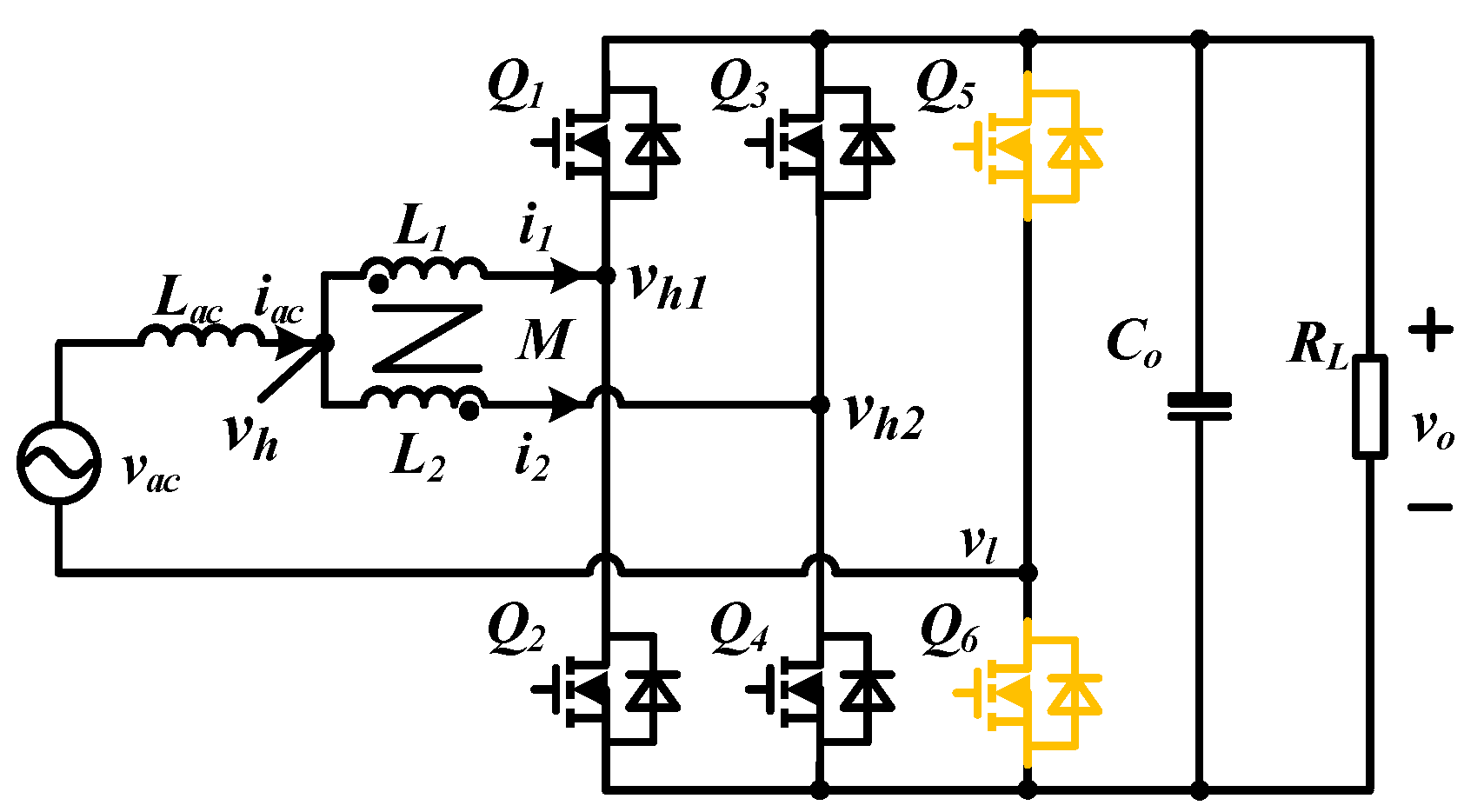
The topology of a coupled-inductor-based interleaving totem-pole PFC converter is shown in Figure 1. Different from the normal inductors, a coupled inductor can benefit the converter in the following ways:
- The coupling of common mode can restrain the circulating current between phases to decrease the switching loss and conduction loss;
- Mutual inductance benefits the current balance, so no extra sampling and control circuits are needed;
- The close-coupled inductor and input AC filter inductor are made by different materials and integrated together, which can make full use of the magnetic cores to decrease the weight, volume, and loss of magnetic components.
Since the actual system is complex, several assumptions are made to simplify the analysis:
- All switches are ideal;
- The equivalent input resistance of the inductors is r, inductance value L1 = L2 = L, output capacity is Co, load resistance is RL;
- The output filter capacitor is large enough to keep the output voltage stable;
- The converter works in CCM.
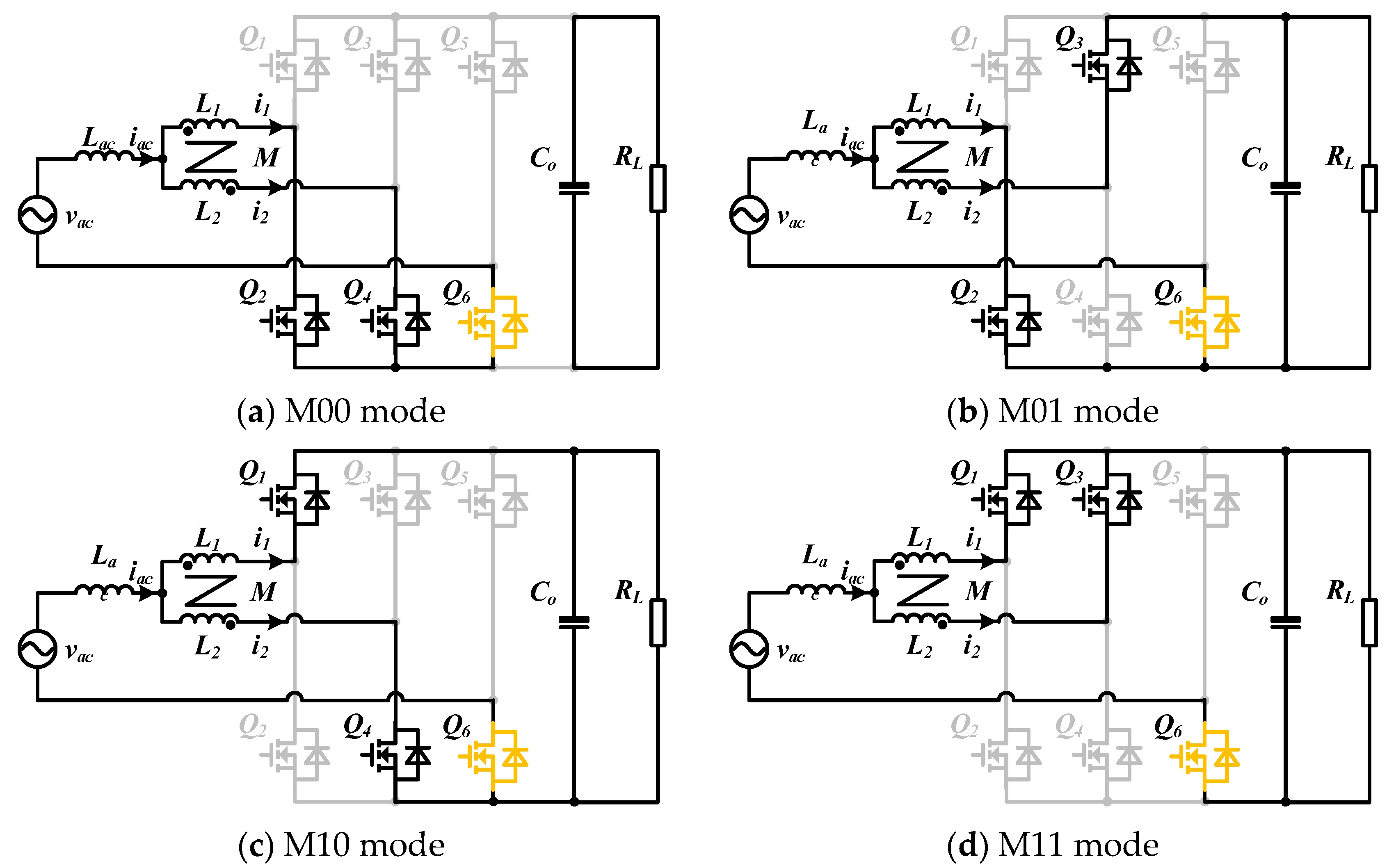
Due to the interleaving of driver signals, two switches in the same bridge are complementary to each other, and the phase difference between the two bridge arms is 180 degrees. The switching mode is defined as Mxy, where x and y represent the switching state of each bridge.
The state of the upper switch is defined as 1 when it is on, and the state is 0 when it is off. The whole converter consists of four switching modes, named M00, M01, M10 and M11, and the corresponding circuit modes for each switching state are shown as Figure 2. The working state of the circuit is similar when the input voltage is in the positive and negative half-cycles, the working modes of the totem are symmetric in a period, and the analysis of the working mode can take the positive cycle as an example.
According to Figure 2, the state space model of interleaved totem-pole PFC converter can be obtained as Formula (1).
In Formula (1), the state variables are shown as Formula (2), r and L are the resistance and inductance of the inductor, i1, i2 and vac are the input voltage and voltage of the converter as shown in Figure 2, and x and y are the numbers of the mode defined above.
Based on Formulas (1) and (2), the state-space-averaging method can be used to calculate the state space average model. By introducing small signal disturbance into the model, the transfer function of small signals can be obtained as Formula (3).
Since the resistance r is far smaller than the impedance of the inductor, r can be ignored and Formula (3) can be simplified as Formula (4).
If only the low-frequency characteristics are considered, the input voltage vc and duty ratio D can also be ignored, and the transfer function can be finally simplified as Formula (5).
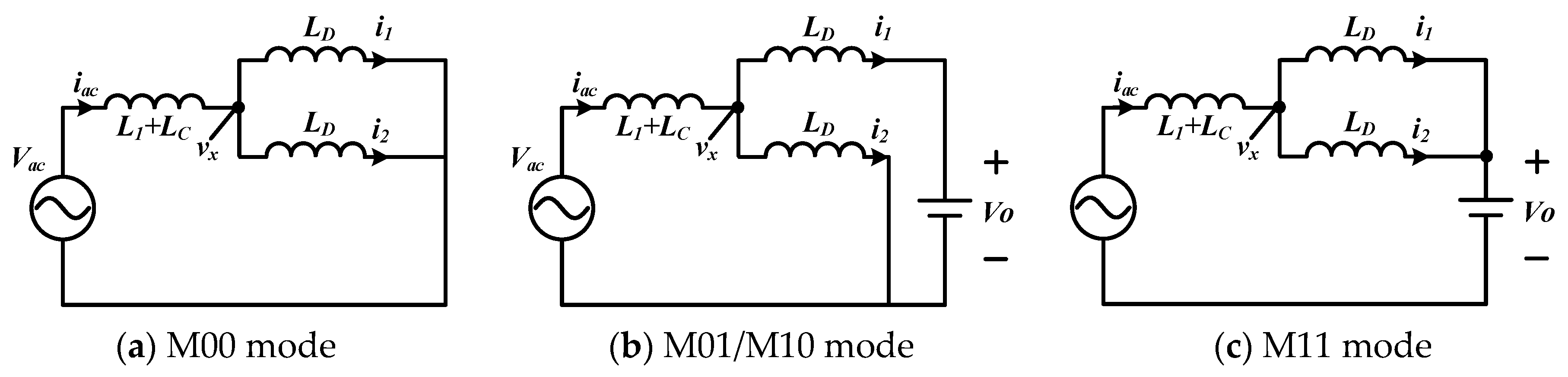
The coupled inductor can also be simplified by equivalent inductors, where the inductance of the input AC filter inductor is Lac, equivalent input filter inductance after decoupling is L, common mode equivalent inductance is LC, circulation suppression inductance is LD, L1 and L2 are self-inductances of the coupled windings, and M is the mutual inductance of the coupled inductor. Assuming that L1 is equal to L2, the equivalent parameters of the decoupled circuits are shown as Formula (6).
As shown in Figure 3, switching modes can be analyzed through equivalent circuits: mode M10 and mode M01 have similar equivalent circuits.
By analyzing the circuit equations, the current change rates of different modes can be obtained; the results are shown in Table 1.
Due to the double-frequency and multilevel output performance of two-phase coupled inductors, mutual inductance would help restrain the circulation current and reduce the peak value ICC of the circulation current, and the equivalent switching frequency is twice the switching frequency, as shown in Formula (7).
2.2. Current Ripple and Circulation Current
The current change in each stage is related to the input voltage, output voltage, and inductance value. In order to accurately describe the current ripple change rule in a period, four regions can be divided by the value of input voltage, as shown in Figure 4.
Voltages v1, v2, v3 are decided by the input voltage, output voltage, equivalent self-inductance and mutual inductance; these voltages can be calculated using Formula (8).
Due to the interleaving, the input current changes twice in one period, so the equivalent frequency of current ripple is twice the switching frequency. The changes of input current in the adjacent modes are the same, and the input current ripple can be calculated by either mode.
When vac < 0.5vo, the mode change sequence is M00-M01-M00-M10. If the input voltage is in region 1 (0 < vac < v1), the current variation is negative, and if it is in region 2 (v1 < vac < v2), the current variation is positive. The waveform is shown in Figure 5.
In the M00 mode, the current variation in winding of the coupled inductor is always positive, and its value is exactly half of the total input current.
When vac = 0.5vo, the mode change sequence is M01-M01-M10-M10, and total current ripple is 0 in this condition. As shown in Figure 6, the ripples are eliminated by each other.
When vac > 0.5vo, as shown in Figure 7, the mode change sequence is M01-M11-M10-M11. If the input voltage is in region 3 (v2 < vac < v3), the current variation is negative, and if it is in region 4 (v3 < vac), the current variation is positive. In addition, current variation in the M01 mode is always positive whether in region 3 or region 4, and its amplitude is exactly equal to the peak value of the current ripple, which can be used as the calculation basis of the current ripple in the region.
By summarizing the above analysis, the current ripple of grid current and phase current in different conditions can be obtained through circuit equations. The results of total current iac and winding current i1 with modes in the positive half period are shown in Table 2.
3. Zero-Crossing Distortion Inhibitory Strategy
3.1. Mechanism of Zero-Crossing Distortion
Bi-directional totem-pole PFC converters can operate in both the rectification mode and inversion mode. Due to the duality of the two modes, we can take the rectification mode as an example to analyze the operation process.
Assuming that the RMS values of input voltage and current are Vac and Iac, the power factor of the PFC converter is 1, and ignoring the resistance of the inductor, the rectification mode operation analysis can be simplified by Figure 8.
Input currents and voltages are required to be sinusoidal in the operation of the PFC converter, so the input voltage vac, input current iL, and equivalent bridge midpoint voltage vhl can be shown as in Figure 9.
θ is the phase where the equivalent bridge midpoint voltage vhl lags grid voltage vac. The value of θ can be calculated by Equation (9).
The equivalent bridge midpoint voltage vhl can be calculated by θ, as shown in (10).
Then, the expressions of duty cycles of different bridges can also be calculated by Formula (11).
Conventional control system of the totem-pole PFC converter is shown in Figure 10. The input voltage vac is sampled to determine the polarity of the modulation signal, which is directly related to the voltage vhl.
According to the phasor diagram in Figure 8, the equivalent bridge midpoint voltage vhl always lags behind the input voltage vac. When the voltage is around the zero-crossing point, the phase difference would result in the faulty judgement of the polarity determined by the input voltage vac; thus, an unexpected variation of current would happen, and the error modulation signal would cause the distortion of input current.
To eliminate the current peak and oscillation around the zero-crossing point, the traditional totem-pole PFC converter uses methods such as turning off the drive signal, phase compensation, and hybrid PWM modulation, but these methods are not suitable for the interleaving converter. Due to the double-frequency and multilevel characteristics of bridge midpoint output voltage, the input AC filter inductor can use a smaller inductance, but it will also increase the peak current of zero-crossing distortion, worsen the input THD, trigger the over-current protection, and shut down the converter.
3.2. Improved Control Strategy
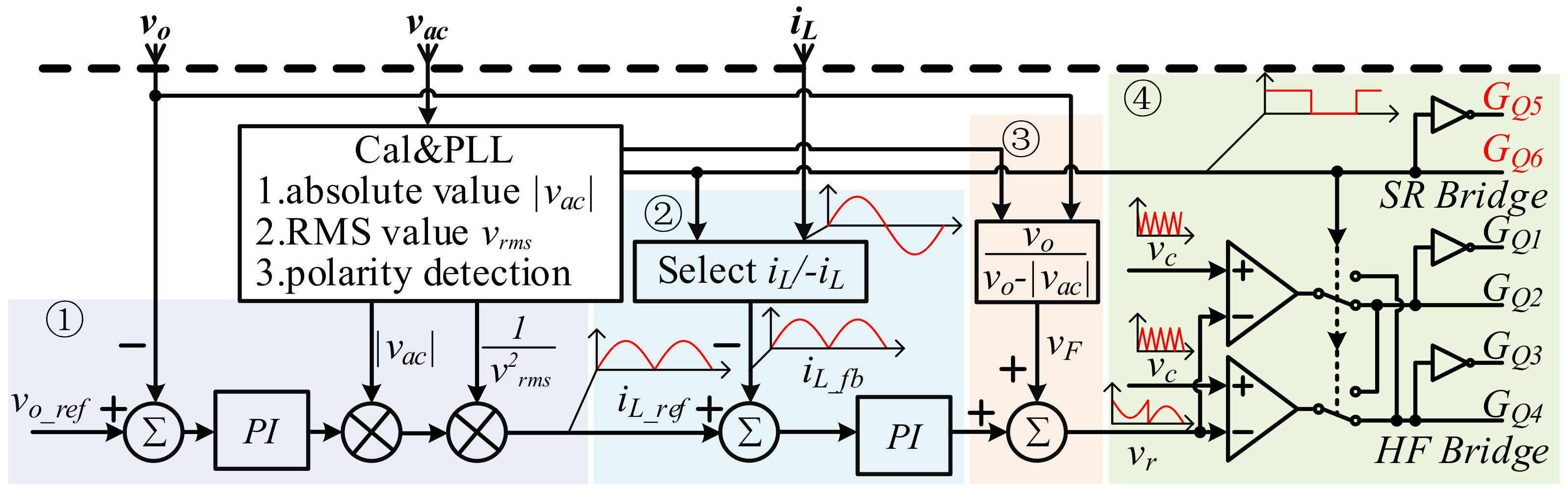
To solve distortion problems, the polarity of PWM modulation should be improved. If the current feedback signal and current control reference are both in the sinusoidal form, the current control output signal will automatically synchronize with phase, which can not only avoid the distortion caused by phase difference, but also decrease the requirement for current control design. The improved control strategy is shown in Figure 11.
The transfer function of the coupled-inductor-based interleaving totem-pole PFC converter is shown as Equation (12).
In an improved controller, the current reference and feedback signal are 50 Hz sinusoidal signal; thus, a parallel PIR controller can be used to eliminate the odd-number harmonic current, and transfer function of the PIR controller is shown as (13).
The equivalent inductance of the filter inductor will change with input current. When the totem-pole PFC converter is in no-load operation mode, the equivalent inductance of the AC filter inductor is about 874 μH, and when the converter is in full-load operation, the equivalent inductance is about 768 μH. Due to the wide range in the change of inductance, it is necessary to make the bandwidth large enough to ensure that input current has a good sinusoidal degree near zero voltage. The inductance of the coupled inductor is much larger than the AC filter inductor, so the change of AC filter inductance would not have a great influence on the control system.
The design of the controller needs to guarantee the stability of the controller when the parameters change. In this paper, the value of the KP is 0.01492, KI is 7.27432, KR1 is 10, and KR3, KR5, and KR7 are 5. The Bode diagram of the PIR controller is shown in Figure 12. Cross-over frequency is 4.06 kHz in no-load operation mode and 4.45 k in full-load operation mode, and phase margin is 42.5° in no-load operation mode and 40.2° in full-load operation mode.
4. Experiments
To verify that the improved control strategy can optimize efficiency and THD for a coupled-inductor-based bi-directional interleaving totem-pole PFC converter, a 50 kHz and 7.7 kW interleaving totem-pole PFC converter was used. The AC filter inductor and coupled inductor are shown as (a) and (b) in Figure 13, and a platform using a 7.7 kW totem-pole converter is shown as (c) in Figure 13. The parameters are shown in Table 3.
In the traditional control strategy, phase deviation will always occur near the zero-crossing point, which results in a current peak and oscillation. The smaller the equivalent inductance is, the more serious the current peak will be, and the reverse recovery loss will also increase, and the switches will be damaged.
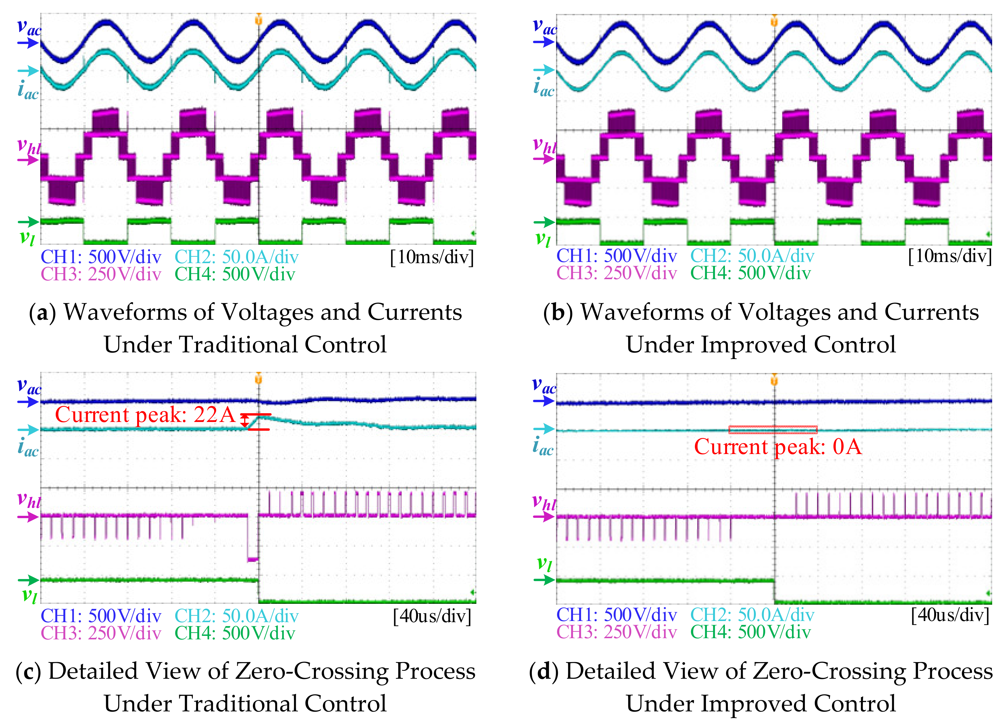
Figure 14 and Figure 15 show a comparison of traditional control and improved control. It is obvious that the current peak around the zero-crossing point is eliminated, as current peak is 22 A in traditional control and 0 in improved control, which verifies the feasibility and effectiveness of the improved control strategy for the totem-pole PFC converter.
Obviously, current peak caused by zero-crossing distortion can be effectively eliminated by the improved control. The THD and efficiency of the converter would also be improved due to the improvement of current. The THD and power-factor relationship with output power in the inverter mode and rectifier mode are shown in Figure 16. Under 15% full load, the power factor can reach 0.98, and under the full load the power factor is 0.9989. In addition, THD is less than 15% at 15% full load, less than 5% at 30% full load, and less than 3% at half load. Under full-load operation, the minimum THD is 1.87% in rectifier mode and 2.18% in inverter mode. Efficiency is also improved. Efficiency is always higher than 98% when the output power is more than 10% full load. The maximum efficiency is 99.29% in inverter mode and 99.07% in rectifier mode. This result is compliant with IEC 61000-3-2, which means even though the system uses a smaller filter, THD can still satisfy the standard.
5. Conclusions
In this paper, the deterioration of the zero-crossing distortion caused by coupled inductors is analyzed. To eliminate the zero-crossing distortion as well as reduce the weight and volume of the magnetic components, an improved control strategy suitable for interleaving totem-pole PFC converters and an implementation method for digital control systems are proposed. Through experiments, the method proved to be effective in eliminating the zero-crossing distortion as well as ensuring the efficient, stable and reliable operation of the converter.
Author Contributions
Conceptualization, Q.L.; methodoSSlogy, Q.L.; software, Y.L.; validation, Y.L.; formal analysis, Q.L.; investigation, Q.L.; resources, S.D.; data curation, Q.L.; writing—original draft preparation, H.F.; writing—review and editing, H.F.; visualization, H.F.; supervision, S.D.; project administration, S.D.; funding acquisition, S.D. All authors have read and agreed to the published version of the manuscript.
Funding
This research received no external funding.
Institutional Review Board Statement
Not applicable.
Informed Consent Statement
Not applicable.
Data Availability Statement
Data available on request from the authors. The data that support the findings of this study are available from the corresponding author, upon reasonable request.
Conflicts of Interest
The authors declare no conflict of interest.
References
- Kazemtarghi, A.; Chandwani, A.; Ishraq, N.; Mallik, A. Active Compensation-based Harmonic Reduction Technique to Mitigate Power Quality Impacts of EV Charging Systems. IEEE Trans. Transp. Electrif. 2022. [Google Scholar] [CrossRef]
- Kim, Y.; Sung, W.; Lee, B. Comparative Performance Analysis of High Density and Efficiency PFC Topologies. IEEE Trans. Power Electron. 2014, 29, 2666–2679. [Google Scholar] [CrossRef]
- Neto, R.M.F.; Tofoli, F.L.; DeFreitas, L.C. A High-Power-Factor Half-Bridge Doubler Boost Converter Without Commutation Losses. IEEE Trans. Ind. Electron. 2005, 52, 1278–1285. [Google Scholar] [CrossRef]
- Kim, D.; Jeong, Y.; Lim, C.; Kang, B.; Moon, G. Bidirectional Bridgeless PFC with Reduced Input Current Distortion and Switching Loss Using Gate Skipping Technique. In Proceedings of the 2016 IEEE Transportation Electrification Conference and Expo, Asia-Pacific (ITEC Asia-Pacific), Busan, Korea, 1–4 June 2016; pp. 579–583. [Google Scholar]
- Huber, L.; Irving, B.T.; Jovanovic, M.M. Open-Loop Control Methods for Interleaved DCM/CCM Boundary Boost PFC Converters. IEEE Trans. Power Electron. 2008, 23, 1649–1657. [Google Scholar] [CrossRef]
- Wu, M.; Li, S.; Tan, S.; Hui, S.Y. Optimal Design of Integrated Magnetics for Differential Rectifiers and Inverters. IEEE Trans. Power Electron. 2018, 33, 4616–4626. [Google Scholar] [CrossRef]
- Barry, B.C.; Hayes, J.G.; Rylko, M.S.; Stala, R.; Penczek, A.; Mondzik, A.; Ryan, R.T. Small-Signal Model of the Two-Phase Interleaved Coupled-Inductor Boost Converter. IEEE Trans. Power Electron. 2018, 33, 8052–8064. [Google Scholar] [CrossRef]
- Khan, A.A.; Cha, H.; Kim, H. Magnetic Integration of Discrete-Coupled Inductors in Single-Phase Direct PWM AC–AC Converters. IEEE Trans. Power Electron. 2016, 31, 2129–2138. [Google Scholar] [CrossRef]
- Zhu, K.; O’Grady, M.; Dodge, J.; Bendel, J.; Hostetler, J.L. 1.5 kW single phase CCM totem-pole PFC using 650V SiC cascodes. In Proceedings of the 2016 IEEE 4th Workshop on Wide Bandgap Power Devices and Applications (WiPDA), Fayetteville, AR, USA, 7–9 November 2016. [Google Scholar]
- Amiri, P.; Eberle, W.; Gautam, D.; Botting, C. An Adaptive Method for DC Current Reduction in Totem Pole Power Factor Correction Converters. IEEE Trans. Power Electron. 2021, 36, 11900–11909. [Google Scholar] [CrossRef]
- Liu, Z.; Huang, Z.; Lee, F.C.; Li, Q. Digital-Based Interleaving Control for GaN-Based MHz CRM Totem-Pole PFC. IEEE J. Emerg. Sel. Top. Power Electron. 2016, 4, 808–814. [Google Scholar] [CrossRef]
- Park, M.; Baek, J.; Jeong, Y.; Moon, G. An Interleaved Totem-Pole Bridgeless Boost PFC Converter with Soft-Switching Capability Adopting Phase-Shifting Control. IEEE Trans. Power Electron. 2019, 34, 10610–10618. [Google Scholar] [CrossRef]
- Sun, J.; Gui, H.; Li, J.; Huang, X.; Strain, N.; Costinett, D.J.; Tolbert, L.M. Mitigation of Current Distortion for GaN-Based CRM Totem-Pole PFC Rectifier With ZVS Control. IEEE Open J. Power Electron. 2021, 2, 290–303. [Google Scholar] [CrossRef]
- Huang, Z.; Liu, Z.; Li, Q.; Lee, F.C. Microcontroller-Based MHz Totem-Pole PFC with Critical Mode Control. In Proceedings of the 2016 IEEE Energy Conversion Congress and Exposition (ECCE), Milwaukee, WI, USA, 18–22 September 2016; pp. 1–8. [Google Scholar]
- Liu, Z.; Lee, F.C.; Qiang, L.; Yang, Y. Design of GaN-Based MHz Totem-Pole PFC Rectifier. IEEE J. Emerg. Sel. Top. Power Electron. 2016, 4, 799–807. [Google Scholar] [CrossRef]
- Chen, T.; Cheng, H.; Wang, C.; Chen, W.; Zhao, Z. Open-Circuit Fault-Tolerant Design of the Cascaded H-Bridge Rectifier Incorporating Reactive Power Compensation. Electronics 2020, 9, 1490. [Google Scholar] [CrossRef]
- Marcos-Pastor, A.; Vidal-Idiarte, E.; Cid-Pastor, A.; Martinez-Salamero, L. Loss-Free Resistor-Based Power Factor Correction Using a Semi-Bridgeless Boost Rectifier in Sliding-Mode Control. IEEE Trans. Power Electron. 2015, 30, 5842–5853. [Google Scholar] [CrossRef] [Green Version]
- Fiorio, L.V.; Dezuo, T.; Novaes, Y. Switched Control Applied to a Totem-Pole Bridgeless Rectifier for Power Factor Correction. Electr. Eng. Syst. Sci. 2021, 1–6. [Google Scholar]
- Fischer, G.D.S.; Rech, C.; de Novaes, Y.R. Extensions of Leading-Edge Modulated One-Cycle Control for Totem-Pole Bridgeless Rectifiers. IEEE Trans. Power Electron. 2020, 35, 5447–5460. [Google Scholar] [CrossRef]
- Qiqi, L.I.; Liu, B.; Duan, S. Predictive Control Algorithm Considering the Soft Saturation Nature of the Inductors for Totem-pole PFC Converter. Proc. CSEE 2019, 39, 6365–6373. [Google Scholar]
- Fan, J.W.; Yeung, R.S.; Chung, H.S. Optimized Hybrid PWM Scheme for Mitigating Zero-Crossing Distortion in Totem-Pole Bridgeless PFC. IEEE Trans. Power Electron. 2019, 34, 928–942. [Google Scholar] [CrossRef]
Figure 1.
Coupled-inductor-based interleaving totem-pole PFC converter.

Figure 2.
Different switching modes in positive cycle: (a) current path in M00 mode; (b) current path in M01 mode; (c) current path in M10 mode; (d) current path in M11 mode.
Figure 2.
Different switching modes in positive cycle: (a) current path in M00 mode; (b) current path in M01 mode; (c) current path in M10 mode; (d) current path in M11 mode.

Figure 3.
Equivalent circuits of different modes: (a) equivalent circuit in M00 mode; (b) equivalent circuit in M01 and M10 modes; (c) equivalent circuit in M11 mode.
Figure 3.
Equivalent circuits of different modes: (a) equivalent circuit in M00 mode; (b) equivalent circuit in M01 and M10 modes; (c) equivalent circuit in M11 mode.

Figure 4.
Region diagram determined by input voltage vac.

Figure 5.
Input current diagram when vac < 0.5vo: (a) waveform of currents and drive signals when 0 < vac < v1; (b) waveform of currents and drive signals when v1 < vac < v2.
Figure 5.
Input current diagram when vac < 0.5vo: (a) waveform of currents and drive signals when 0 < vac < v1; (b) waveform of currents and drive signals when v1 < vac < v2.

Figure 6.
Input current diagram when vac = 0.5vo.

Figure 7.
Input current diagram when vac > 0.5vo: (a) waveform of currents and drive signals when v2 < vac < v3; (b) waveform of currents and drive signals when v3 < vac.
Figure 7.
Input current diagram when vac > 0.5vo: (a) waveform of currents and drive signals when v2 < vac < v3; (b) waveform of currents and drive signals when v3 < vac.

Figure 8.
Equivalent circuit and phasor diagram of rectification mode: (a) equivalent circuit of fundamental wave; (b) phasor diagram of voltage and current.
Figure 8.
Equivalent circuit and phasor diagram of rectification mode: (a) equivalent circuit of fundamental wave; (b) phasor diagram of voltage and current.

Figure 9.
Steady-state operation input waveform.

Figure 10.
Traditional control strategy block diagram of totem-pole PFC converter.

Figure 11.
Improved control strategy block diagram of interleaving totem-pole PFC converter.

Figure 12.
Open-loop Bode diagram of the PIR controller.

Figure 13.
Platform for experimental verification: (a) filter inductor using magnetic powder core; (b) coupled inductor using ferrite; (c) 7.7 kW totem-pole PFC converter used for experiments.
Figure 13.
Platform for experimental verification: (a) filter inductor using magnetic powder core; (b) coupled inductor using ferrite; (c) 7.7 kW totem-pole PFC converter used for experiments.

Figure 14.
Control comparison experiments in no-load operation mode: (a) experiment under traditional control; (b) experiment under improved control; (c) detailed view of zero-crossing process (the current peak of zero-crossing distortion is 21 A); (d) detailed view of zero-crossing process (zero-crossing distortion is eliminated).

Figure 15.
Control comparison experiments when RL = 26 Ω: (a) experiment under traditional control; (b) experiment under improved control; (c) detailed view of zero-crossing process (current peak of zero-crossing distortion is 22 A); (d) detailed view of zero-crossing process (zero-crossing distortion is eliminated).

Figure 16.
Power factor and THD relationship with power: (a) graph of power factor and grid-side power both in inverter mode and rectifier mode; (b) graph of THD and grid-side power both in inverter mode and rectifier mode; (c) graph of efficiency and grid-side power both in inverter mode and rectifier mode.


Table 1.
Current change rate of different modes.
| Mode | ||
|---|---|---|
| M00 | ||
| M01 | ||
| M10 | ||
| M11 |
Table 2.
Current ripple in half period of different conditions.
| vac Value | Mode | Δiac | Δi1 |
|---|---|---|---|
| <0.5vo | 00 | ||
| 01 | |||
| 00 | |||
| 10 | |||
| =0.5vo | 01 | 0 | |
| 10 | 0 | ||
| >0.5vo | 11 | ||
| 10 | |||
| 11 | |||
| 01 |
Table 3.
Circuit parameters of coupled inductor and interleaved totem-pole converter.
| Component | Parameter | Value | Parameter | Value |
|---|---|---|---|---|
| Circuit | Vac | 220 V rms | Vo | 390 V DC |
| Iac | 35 A rms | Po | 7.7 kW | |
| fs | 50 kHz | Co | 3120 μF | |
| AC Filter Inductor | Lac (0A) | 176 μH | Lac (49.5A) | 67.2 μH |
| Core Type | High Flux 58083 | N1 | 33 | |
| N2 | 33 | Wire | 0.1 × 300 | |
| Couple Inductor | L2 | 698 μH | M | 697.5 μH |
| Core Type | NCD LP9 PQ40/40 | N3 | 20 | |
| N4 | 20 | Wire | 0.1 × 300 | |
| Vac | 220 V rms | Vo | 390 V DC |
Publisher’s Note: MDPI stays neutral with regard to jurisdictional claims in published maps and institutional affiliations. |
© 2022 by the authors. Licensee MDPI, Basel, Switzerland. This article is an open access article distributed under the terms and conditions of the Creative Commons Attribution (CC BY) license (https://creativecommons.org/licenses/by/4.0/).
Share and Cite
MDPI and ACS Style
Fu, H.; Duan, S.; Li, Y.; Li, Q. Improved Control Strategy for Zero-Crossing Distortion Elimination in Totem-Pole PFC Converter with Coupled Inductor. Energies 2022, 15, 5437. https://0-doi-org.brum.beds.ac.uk/10.3390/en15155437
AMA Style
Fu H, Duan S, Li Y, Li Q. Improved Control Strategy for Zero-Crossing Distortion Elimination in Totem-Pole PFC Converter with Coupled Inductor. Energies. 2022; 15(15):5437. https://0-doi-org.brum.beds.ac.uk/10.3390/en15155437
Chicago/Turabian StyleFu, Han, Shanxu Duan, Yong Li, and Qiqi Li. 2022. "Improved Control Strategy for Zero-Crossing Distortion Elimination in Totem-Pole PFC Converter with Coupled Inductor" Energies 15, no. 15: 5437. https://0-doi-org.brum.beds.ac.uk/10.3390/en15155437
Note that from the first issue of 2016, this journal uses article numbers instead of page numbers. See further details here.