
Multi-Pulse Rectifier Based on an Optimal Pulse Doubling Technique


1
Department of Electrical Engineering, Technical and Vocational University (TVU), Tehran 14357-61137, Iran
2
Electrical Engineering Department, Amirkabir University of Technology, Tehran 15916-39675, Iran
3
Department of Electrical and Computer Engineering, University of Windsor, Windsor, ON N9B 1K3, Canada
4
Malaviya National Institute of Technology Jaipur, Jaipur 302017, Rajasthan, India
*
Author to whom correspondence should be addressed.
Energies 2022, 15(15), 5567; https://0-doi-org.brum.beds.ac.uk/10.3390/en15155567
Submission received: 2 December 2021
/
Revised: 19 June 2022
/
Accepted: 27 June 2022
/
Published: 31 July 2022
(This article belongs to the Special Issue Optimization and Control of Renewable Energy Sources in Smart Grid)
Abstract
:This paper presents pulse multiplication technology based on an optimal Pulse Doubling Technique (PDT) to upgrade a 28-Pulse Rectifier (28-PR) to a 56-PR. The optimal PDT comprises a Tapped Interphase Reactor (TIPR) with a low kVA-rating and two diodes. The number of pulses can be increased from 28 to 56 using the PDT so that the input current harmonics are reasonably mitigated. Additionally, the 14-phase Polygon-Connected Autotransformer (PCA) is designed in such a way that it can be used for retrofit applications. A detailed simulation analysis in the MATLAB/Simulink environment is carried out, and the results show that the improved quality indices of the final AC input and DC output power are equivalent to the IEEE 519-2014 standard and meet sensitive industrial application requirements with an input current Total Harmonic Distortion (THD) lower than 3%. Moreover, the power factor also maintained unity for a wide operating range. The optimal PDT scheme is affordable and easy to implement as only a small-capacity PDT (only 1% of the output power) is needed to double the pulse number. An experimental prototype is developed to verify the simulation results.
1. Introduction
Advancement in power electronics has led rectifiers to be utilized in many industrial applications. These rectifiers are mostly fed from a front-end uncontrolled six-pulse Diode Bridge Rectifier (DBR). Front-end six-pulse DBRs draw harmonic-rich current from the input AC source, thereby, degrading the power quality and resulting in a poor power factor. Besides this, the harmonic-rich current causes a harmonic-rich voltage at the Point of Common Coupling (PCC), which results in voltage fluctuations at the customer end. Since the power quality indices can be well-maintained within the limits set by the regulatory agents, such as IEEE 519-2014 standard [1], much attention has been paid to power quality improvement techniques [2].
Using multi-pulse rectifiers can be considered an effective method to improve the power quality [3,4]. Several studies have been presented on the use of 12- [5,6], 18- [7,8], 20- [9] and 24-Pulse Rectifiers (PRs) [10,11] to reduce harmonics issues. Using multi-pulse rectifiers results in line current Total Harmonic Distortion (THD) exceeding 5% under a light load or source with lower impedance. Sensitive industrial applications follow stringent power quality indices, and it is preferable to use above 24-PRs [12]. Hence, the magnitude of the harmonics is maintained below 3% in such applications. However the proposed 36- [13] and 40-PRs [14] improve the power quality, the increased magnetic ratings and higher degree of complexity can be considered as their major drawbacks.
According to the reported results in [14], in light load conditions and with low source impedance, in rectifiers up to 40 pulses, the sensitive industrial application requirements with an input current THD lower than 3% have not yet been met. Although an increase in the number of pulses results in improved power quality indices, the cost and size of the rectifier also increase. To avoid increasing the complexity, size, and cost of the rectifier, the use of pulse multiplications is recommended [15,16,17,18]. The Pulse Doubling Technique (PDT), presented in [15], is based on two Tapped Interphase Reactors (TIPRs) and a single-phase DBR, which has six operating modes according to the relationship between TIPRs’ voltage and the load voltage. The main advantage of this structure is its low kVA-rating. However, its power losses are considerable, and it also has a higher number of diodes than other PDTs, which leads to an increase in the cost of this PDT. The PDT presented in [16] is based on two TIPRs and a single-phase full-wave rectifier. The primary winding of the TIPR and two diodes form the first passive harmonic reduction circuit, and the secondary winding of the TIPR and two diodes constitute the second harmonic reduction circuit. This PDT reduces the harmonic distortions of the input current significantly, but its structure is complex and has high power losses and a high kVA-rating. In [17], a single-phase DBR-based PDT is proposed. The relationship between the load voltage and the secondary winding of the TIPR determines the number of pulses. In this PDT, the diodes of the PDT are installed on the secondary side of the TIPR, which reduces the current flow passing through such diodes, and thus, reduces the connection losses of the diodes in this PDT. However, the kVA-rating and the cost of this PDT are notably high. The PDT proposed in [18] is based on two single-phase full-wave rectifiers and has four operating modes. This PDT can reduce the harmonic distortion of the input current, but it has a very complex structure, high power losses, and a high kVA-rating, resulting in lower efficiency and a higher cost than other PDTs.
In that context, a 56-PR based on a retrofit Polygon-Connected Autotransformer (PCA) and optimal PDT is proposed in this paper to improve the power quality. Initially, a 28-PR is designed, and using a PDT, the output pulse is increased to achieve improved power quality indices. The independent operation of the 14-pulse DBRs is achieved by a Zero-Sequence Blocking Transformer (ZSBT). Furthermore, a TIPR with two diodes is used for pulse multiplication. The TIPR with diodes results in a nearly sinusoidal waveform at the input current and also a lower magnetic rating. Consequently, in this paper, a PDT with an optimal structure and easy manufacturing for a 28-PR is proposed to lower the input current THD and output voltage ripples without increasing the complexity of the proposed rectifier in sensitive industrial applications. The rest of the paper is organized as follows.
In Section 2, the structure of the proposed 56-pulse rectifier is described. Next, in Section 3, the optimal pulse doubling technique is explained and compared to existing PDTs. In Section 4, simulation and laboratory results are presented and analyzed, and finally, a summary is presented in Section 5.
2. Proposed 56-Pulse Rectifier
Figure 1 shows the configuration of the proposed 56-PR. As shown in this figure, it consists of two main sections:
- A 28-PR;
- An optimal PDT structure.
The 28-PR includes a polygon-connected 14-phase autotransformer to generate two sets of seven-phase voltage. Those two seven-phase voltage sets are passed through two 14-pulse DBRs to generate a 28-pulse waveform. By connecting the optimal PDT to the DC-link of those two 17-pulse DBRs, the 28-pulse waveform is then increased to 56 pulses.
2.1. Design of the PCA for the 28-PR
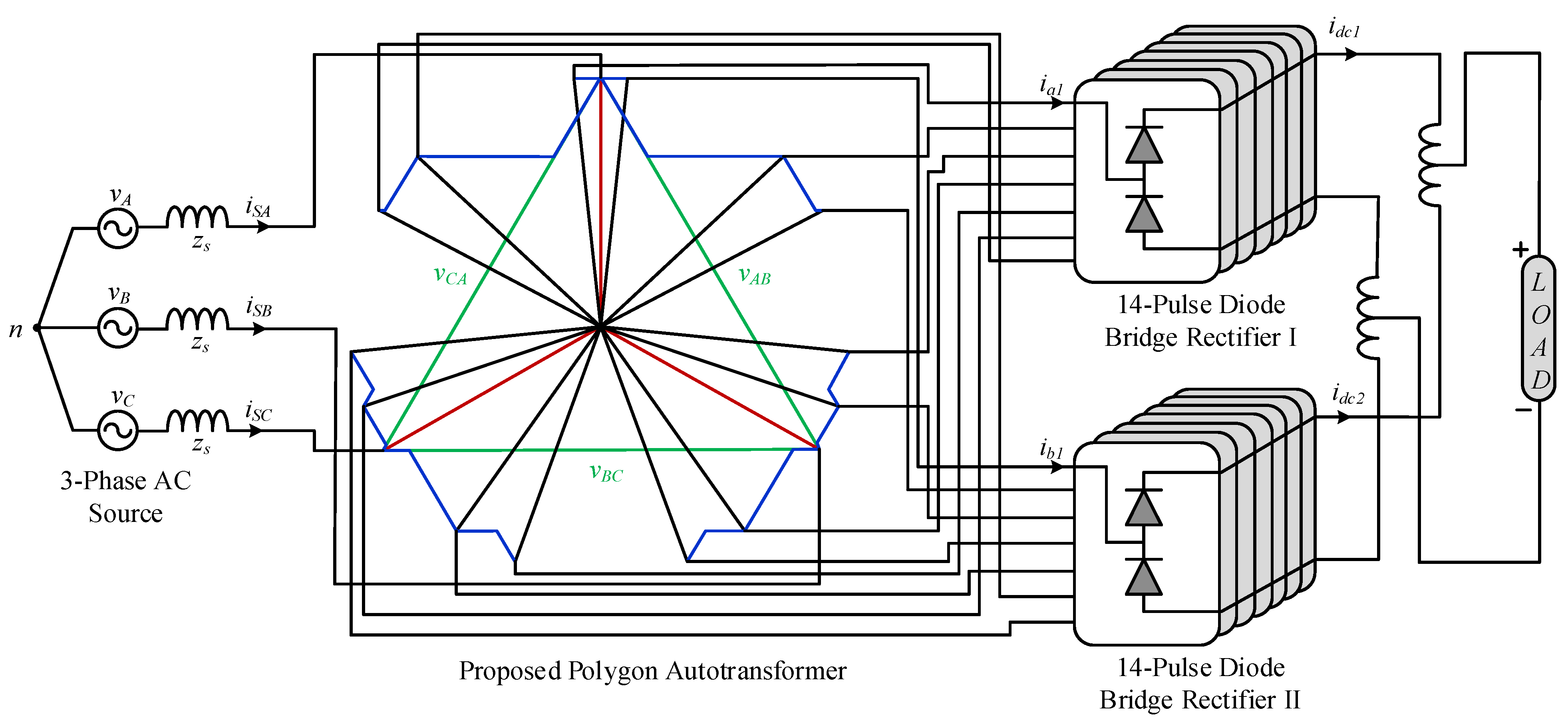
A 28-PR, created by paralleling two 14-pulse DBRs, is shown in Figure 2. This consists of a PCA and generates two seven-phase voltage with phase shifts of 12.86° and 51.43° between the same voltage of the two groups and between the voltage of each group, respectively. The phasor representation and winding connections of the PCA are shown in Figure 3. In addition, it consists of 14-pulse DBRs, and TIPR plays an important role in such a rectifier [1].
As mentioned earlier, the PCA generates two series of seven-phase voltage—group 1, which includes to , and group 2, which includes to —for application to the 14-pulse DBR I and 14-pulse DBR II, respectively. Considering that two seven-leg DBRs are used in the 28-PR, the phase displacement is determined as (360°/(2 × 14)) = 12.86°. Thus, the two 14-pulse DBRs have a phase displacement of 12.86° between them. The phase angle between different phasors is considered +6.34° and −6.34° from the input voltage of phase A.
The seven-phase voltage of the 14-pulse DBR I shown in Figure 3 is as follows:
The seven-phase voltage of the 14-pulse DBR II shown in Figure 3 is as follows:
To obtain the desired phase shift between two voltage groups, the optimal values for winding turns are calculated using Equations (1) and (2). For instance, to calculate constants and , the relationships between and can be used as follows:
In this regard, the relationship between the three-phase supply voltage, , and using the phasor diagram, can be written as follows:
where indicates the amplitude of the phase to the neutral input voltage.
As a result, two equations with two variables are determined. Accordingly, constants and can be calculated. Consequently, constants to are calculated as 0.0042, 0.0625, 0.1910, 0.2481, 0.1168, 0.0222, 0.1297, 0.2995, 0.1016, 0.0439, 0.1014, 0.0116, 0.0773 and 0.2311, respectively.
The calculated values specify the winding turns with respect to the input voltage, and based on such values, the PCA can be simulated and developed. Equation (5) calculates the average output voltage () in the -phase rectifier.
where refers to the peak amplitude of the phase to the neutral input voltage, and represents the number of phases.
Using Equation (5), the output voltage of the conventional six-pulse DBR can be calculated as , and that of the proposed rectifier equals . In other words, the output voltage of the proposed rectifier is 20% higher than that of the conventional six-pulse DBR.
2.2. Design of the Retrofit PCA
Since the output voltage of multi-pulse rectifiers is higher than the standard output voltage of the six-pulse DBR, multi-pulse rectifiers are not suitable for retrofit applications. To address this issue, as shown in Figure 4, the PCA design is modified, whereby its output voltage is reduced so that the output voltage of the 28-PR becomes equal to the output voltage of the six-pulse DBR.
The seven-phase voltage of the 14-pulse DBR I shown in Figure 4 is as follows:
The seven-phase voltage of the 14-pulse DBR II shown in Figure 4 is as follows:
The constants should change for retrofit applications. In this regard, constants to are calculated as 0.1089, 0.1609, 0.2088, 0.0983, 0.0186, 0.0855, 0.0369, 0.0327, 0.1152, 0.1705, 0.1418, 0.0708, and 0.0544, respectively. Such values determine the winding ratios of the PCA required for retrofit applications. The PCA can be simulated and developed using those calculated values.
3. Optimal Pulse Doubling Technique Structure
To increase the number of pulses and avoid an increase in the complexity, size, and cost of multi-pulse rectifiers for a reducing input current THD, a PDT was used. In this paper, by using the simulation results of different types of PDTs, an optimal PDT was selected and used to upgrade the 28-PR. In this regard, different PDTs were simulated using the same input source and under the same loading condition. After that, based on the obtained results, total power losses, the kVA-rating, and the approximate costs of different PDTs were determined. Finally, the optimal PDT was selected and used to upgrade the 28-PR to a 56-PR. The main limitations of the PDT are the performance reduction in the case of harmonics from the source side and also the unbalanced source conditions. Besides, using the PDT may increase the power losses and kVA-rating of multi-pulse rectifiers.
To highlight the main features of the proposed 56-PR, a techno-economic analysis considering the previously presented PDTs and the proposed 56-PR was performed. In this regard, technical indices, kVA-ratings of PDTs, and associated costs, using the proposed method in [17], where the transformer and diode costs were respectively estimated as 4.5 times the transformer kVA-rating and $2.25, were considered. The kVA-rating of a PDT can be estimated using the following equation [3]:
where and are Root Mean Square (RMS) values of the voltage and current of PDT windings, respectively.
Table 1 shows the RMS values of the voltage and current of different PDTs and their VA-ratings for a 10 kVA load. As shown in this table, the VA-rating of the proposed PDT is 62.42 VA, i.e., less than those proposed in [15,16,17,18].
The diode power losses () are calculated using the following equations.
where the voltage drop across the diode () is 0.7 V, the diode internal resistance () is 1 , is the instantaneous current of the diode and is the average current of the diode.
The following equation is used to calculate the core power losses ().
where is the nominal weight of the core, is the core material coefficient, shows the maximum flux density, is the operating frequency and and are the Steinmetz coefficients.
It should be noted that the parameters used were obtained from [9].
The weight of the transformer () can be determined using the following empirical expression.
where is the constant related to the core configuration for a laminated core, and are the waveform coefficient and window utilization factor, respectively, and is the nominal power of the transformer.
The total weight of the transformer can be estimated using the weight of the core and the weight of all windings. Generally, 75% of the total weight of the transformer can be considered the nominal weight of the core, i.e., .
The copper power losses () can be calculated as follows.
where is the current density, is the electrical resistivity of copper, , , , and are the mean length per turn, the number of turns, the AC/DC resistance factor considering the skin effect, and the RMS value of the current of the th winding, respectively.
As shown in Table 1, the RMS values of the voltage and current, as well as the VA-rating, of the proposed PDT are given. Considering the voltage per turn of the transformer as 1 and also the mean length per turn with respect to the average cross-sectional area of a core as 10 cm, the number of turns of the winding can be estimated.
Taking Equations (9)–(12) and Table 2 into consideration, core power losses for the 28-PR, ZSBT and proposed PDT are 199.84 W, 10.31 W, and 24.83 W, respectively. Therefore, the total losses of 56-PR can be calculated as 234.98 W and its efficiency as 97.7%. In detail, the total power losses of the 28-PR are 199.84 W, including core losses of 49.34 W, copper losses of 49.85 W, and conduction losses of 100.65 W. The total power losses of the ZSBT are 10.31 W, including core losses of 3.47 W and copper losses of 6.84 W, with no conduction losses. The total power losses of the PDT are 24.83 W, including core losses of 2.54 W, copper losses of 3.46 W and conduction losses of 18.83 W.
Figure 5 presents the efficiency of the proposed 56-PR with respect to the output power changes. It is evident that the efficiency is higher than 96% for all the ranges of experiments. More importantly, the efficiency of the proposed 56-PR is 97.7% under the full-load condition.
A comparative analysis of the different PDTs in terms of power losses, total kVA-ratings, number of diodes and the approximate total costs is presented in Table 1. It can be noted that the transformer’s magnetic rating affects the total cost and size of the system as they depend on the magnetic rating. Therefore, the proposed TIPR has a lower kVA-rating, weight and volume, and it incurs less cost. Therefore, it can be concluded that the optimal PDT can provide a techno-economic solution for sensitive industrial applications.
As shown in Table 3, the proposed PDT is the best possible option when considering technical indices, such as a low input current THD and low power losses. Additionally, it is the most reasonable choice when considering economic indices, such as a low kVA-rating and low total cost.
3.1. Tapped Interphase Reactor
As shown in Figure 1, an optimal and high performance TIPR is placed at the output of two 14-pulse DBRs to upgrade the 28-PR to a 56-PR. Figure 6 illustrates the PDT circuit, consisting of a TIPR and two additional diodes. The operation of the optimal PDT circuit is based on the TIPR voltage so that when this voltage is positive, diode D1 turns on and switches to the conduction mode. On the contrary, when this voltage is negative, diode D2 turns on and switches to the conduction mode. It should be noted that the voltage frequency of the TIPR is 14 times the frequency of the input source, resulting in a reduction in the size and weight of the TIPR. Figure 7 shows the DC current waveforms and .
3.2. Zero-Sequence Blocking Transformer
As mentioned, the 28-PR is based on a PCA and two 14-pulse DBRs. Since the proposed PCA relies on an auto-transformer, it requires a ZSBT to eliminate the difference between the output voltage of the two 14-pulse DBRs, and also, to ensure the independent operation of two 14-pulse DBRs. The transformer-based multi-pulse rectifiers do not usually require any ZSBTs while their kVA-ratings are high, and they are mainly used for isolated applications, such as DC electric arc furnaces. Autotransformer-based multi-pulse rectifiers are suggested for their low kVA-rating, but adding a ZSBT to such multi-pulse rectifiers results in an increase in their kVA-rating. In the case of using a 56-PR for a 10 kVA load, the ZSBT rating should be 127.07 W (0.27% of the full-load condition).
4. Results and Discussions
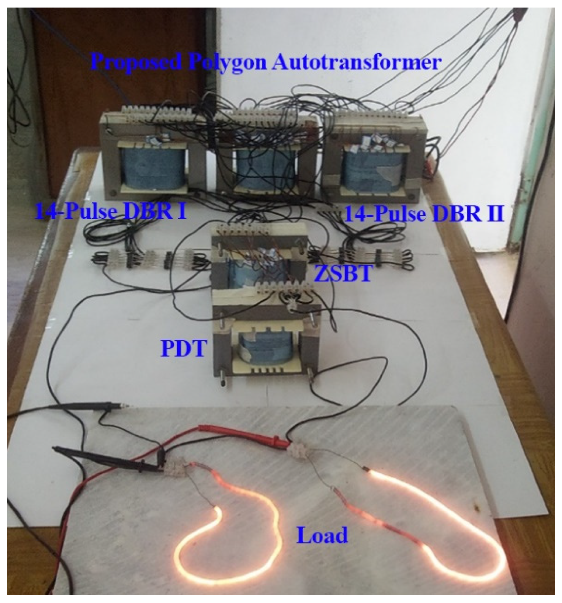
The proposed 56-PR was simulated in the MATLAB/Simulink environment, and the simulation results were verified by conducting experimental tests on the developed laboratory prototype, as shown in Figure 8. The results were measured with a resistance load power of 1 kW and an input phase voltage of 110 V RMS (line-to-line RMS voltage) at 50 Hz.
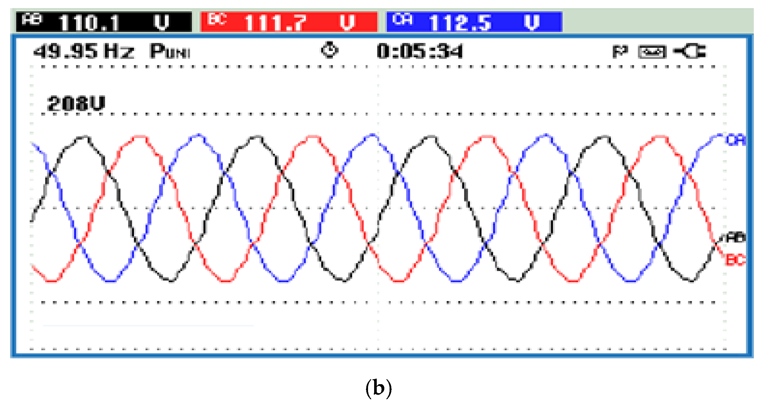
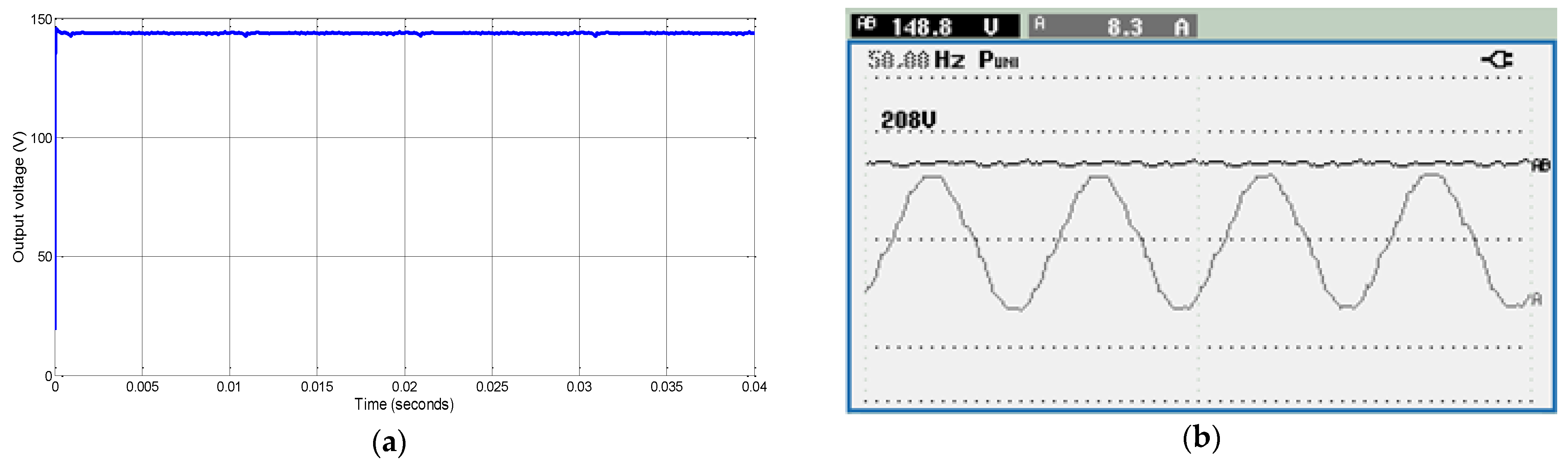
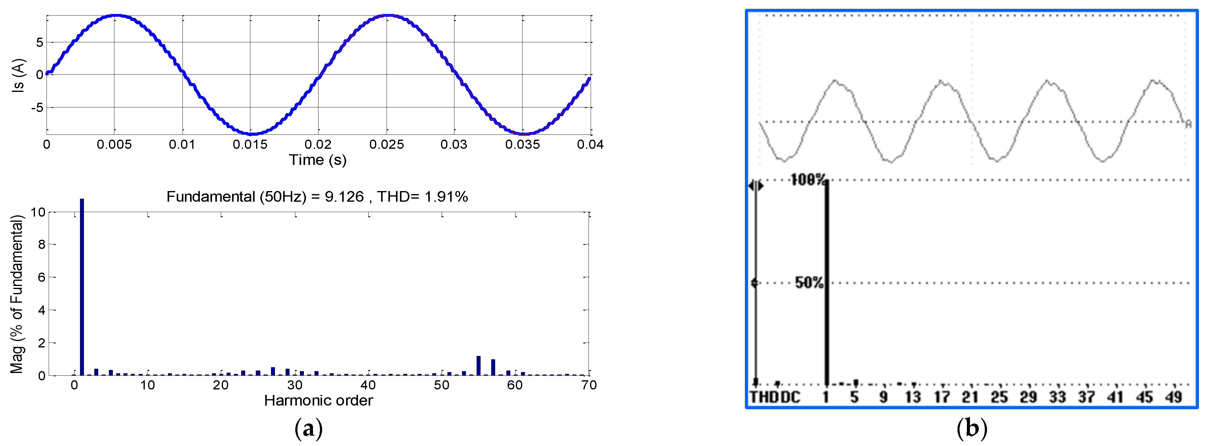
The simulation and experimental results are compared and shown in Figure 9, Figure 10, Figure 11, Figure 12 and Figure 13. Figure 9 shows the PCA input voltage waveforms. It is evident from Figure 10 that the input current is more sinusoidal in shape, and thereby, the power quality indices are improved. Figure 11 demonstrates the bipolar voltage waveform across the TIPR. In addition, the proposed 56-PR output voltage waveform is shown in Figure 12 with smaller voltage ripples. According to Equation (5), the average output voltage is 149 V, which is equal to the DC voltage of the conventional six-pulse DBR at the input line-to-line RMS voltage of 110 V. The results confirm that the proposed 56-PR can be used in retrofit applications. The line current and the Fast Fourier Transform (FFT) of the 56-PR are shown in Figure 13. It can be observed from Figure 13 that the THD of the input line current of the 56-PR is 1.91% in the simulation test, while the measured THD of the input line current of the 56-PR in the experimental test is 2.8%. This demonstrates that the proposed 56-PR meets power quality standards and underscores the superior performance of the proposed converter.
The line input current and harmonic spectrum are shown in Figure 14, where a 10-kW load is applied to the proposed 56-PR. The input current THD is shown in Figure 14a, which is 1.99%. The line input current and the corresponding spectrum are presented in Figure 14b,c under 50% and 20% of the full-load condition, respectively. As can be seen, the THDs are about 2.45% and 2.68%, respectively. The THD under the light-load condition shows a negligible increase while it is under 3%. The harmonic orders of the proposed 56-PR are given in Figure 14d, which are less than 3% and acceptable according to IEEE 519-2014 standard. Slightly higher harmonic orders, i.e., the harmonics in the order of 23–35% and 35–50%, are acceptable for practical cases.
Figure 15 shows the response of the output voltage and input/output current wave-forms to step-load changes. The amplitude of transients depends on the amplitude load change and the inductance of the source. The proposed 56-PR can successfully track load changes.
Table 4 provides the power quality indices obtained from the simulation results of the 28-PR and 56-PR. In addition, the power quality indices are obtained when the load operates under Full-Load (FL) and Light-Load (LL) conditions, with the latter at 20% of the full-load condition. In the case of using a 28-PR, the THDs of the input current are 3.78% and 5.08%, respectively, under full- and light-load conditions, which are not within the standard range. The proposed 56-PR has acceptable THDs for the input current of 1.87% and 2.47% under full- and light-load conditions, respectively. As shown in Figure 13a, the lower-order harmonics up to the 53rd are eliminated from the input current. Moreover, the power factors in full- and light-load conditions are 0.9993 and 0.9991, respectively, which are close to the unity power factor. The magnetic rating of the proposed 56-PR is calculated as 45.63% of the load rating.
As shown in Table 4, the proposed 56-PR has lower THDs of the input current and voltage compared to the 40-PR presented in [14].
Figure 16 compares the proposed 56-PR with the existing multi-pulse rectifiers under the full-load condition based on the THD of the input current and kVA-rating. The THD of the input current of the proposed 56-PR is 1.87%, which is lower than the THD of the input current of existing multi-pulse rectifiers. Such a low THD follows the sensitive industrial application requirements, where the THD of the input current should be less than 3%. Additionally, the kVA-rating of the proposed 56-PR is less than 45.63%, which is approximately the same as the kVA-rating of the 20-PR [9] and 24-PR [11]. It should be noted that the implementation cost of the proposed 56-PR is less than 40-PRs [15]. In other words, the proposed 56-PR provides a techno-economic solution for sensitive industrial applications. As a result, from both a technical (power quality indices) and an economic point of view (kVA-rating and cost), the proposed 56-PR is an optimal solution for sensitive industrial applications.
5. Conclusions
An optimal, passive, economical and robust Pulse Doubling Technique (PDT) was proposed in this paper to upgrade a 28-Pulse Rectifier (28-PR) to a 56-PR without major modifications. The PDT was applied to a 28-PR using the DC ripple re-injection technique, which requires only two diodes and a Tapped Interphase Reactor (TIPR). The simulation and laboratory results show that the Total Harmonic Distortion (THD) of the input current of the proposed 56-PR is notably less than 3%, making it a suitable option for sensitive industrial application requirements. Furthermore, the kVA-rating of the proposed 56-PR is 45.63% of the rated load power, which is great for sensitive industrial applications.
The advantages of the proposed 28-PR with the optimal PDT are summarized as follows:
- It is totally passive and does not require active switching devices. It is an optimal, economical, and robust PDT;
- The 28-PR can be easily upgraded by applying the optimal PDT without major modifications;
- The simulation results show that the input line current THDs of the proposed 28-PR with the optimal PDT are 1.91% and 2.8% in simulation and experimental tests, respectively;
- In the proposed rectifier, an optimal PDT was applied to the 28-PR DC link, which led to a THD of less than 3% and a low kVA-rating, which eliminated the harmonics up to the 56th order, thereby meeting sensitive industrial application requirements without a need for an additional filter.
It should be noted that similar to other PDTs, if the source injects harmonics or the source is unbalanced, the performance of the PDT may be reduced. Plus, the applications may result in greater power losses and increase the kVA-rating of multi-pulse rectifiers.
Continuations of the current work should focus on the magnetic analysis of different PDT circuits and their reliability indices, and also, on the impact of short- and/or open-circuit faults on the performance of PDTs.
Author Contributions
R.A. was responsible for the conceptualization, formal analysis, investigation and writing—original draft preparation, review and editing; G.B.G. and F.M. were responsible for the formal analysis, investigation and writing—original draft preparation, review and editing; S.P.P. was responsible for the writing—original draft preparation. All authors have read and agreed to the published version of the manuscript.
Funding
This research received no external funding.
Institutional Review Board Statement
Not applicable.
Informed Consent Statement
Not applicable.
Data Availability Statement
Data-sharing is not applicable to this article.
Conflicts of Interest
The authors declare no conflict of interest.
References
- IEEE Standard 519-2014; IEEE Recommended Practices and Requirements for Harmonic Control in Electrical Power Systems. IEEE Inc.: New York, NY, USA, 2014.
- Mohammadi, F.; Bok, R.; Hajian, M.; Rezaei-Zare, A. Controller-Hardware-in-the-Loop Testing of A Single-Phase Single-Stage Transformerless Grid-Connected Photovoltaic Inverter. In Proceedings of the 2022 IEEE Texas Power and Energy Conference, College Station, TX, USA, 28 February–1 March 2022. [Google Scholar]
- Paice, D.A. Power Electronic Converter Harmonics: Multipulse Methods for Clean Power; IEEE Press: New York, NY, USA, 1996. [Google Scholar]
- Singh, B.; Gairola, S.; Singh, B.N.; Chandra, A.; Al-Haddad, K. Multipulse AC–DC Converters for Improving Power Quality: A Review. IEEE Trans. Power Electron. 2018, 23, 260–281. [Google Scholar] [CrossRef]
- Chen, J.; Chen, J. On Reducing the Shaft Torque Ripple of Small-to-Medium-Scale Wind Energy Conversion Systems Using Multi-Pulse Autotransformer Rectifier. Energies 2018, 11, 379. [Google Scholar] [CrossRef] [Green Version]
- Corti, F.; Hassan Shehata, A.; Laudani, A.; Cardelli, E. Design and Comparison of the Performance of 12-Pulse Rectifiers for Aerospace Applications. Energies 2021, 14, 6312. [Google Scholar] [CrossRef]
- Khan, S.; Zhang, X.; Saad, M.; Ali, H.; Khan, B.M.; Zaman, H. Comparative Analysis of 18-Pulse Autotransformer Rectifier Unit Topologies with Intrinsic Harmonic Current Cancellation. Energies 2018, 11, 1347. [Google Scholar] [CrossRef] [Green Version]
- Sleszynski, W.; Cichowski, A.; Mysiak, P. Suppression of Supply Current Harmonics of 18-Pulse Diode Rectifier by Series Active Power Filter with LC Coupling. Energies 2020, 13, 6060. [Google Scholar] [CrossRef]
- Prakash, P.S.; Kalpana, R.; Singh, B. Inclusive Design and Development of Front-End Multi-Phase Rectifier with Reduced Magnetic Rating and Improved Efficiency. IEEE J. Emerg. Sel. Top. Power Electron. 2020, 8, 2989–3000. [Google Scholar] [CrossRef]
- Meng, F.; Xu, X.; Gao, L. A Simple Harmonic Reduction Method in Multi-Pulse Rectifier Using Passive Devices. IEEE Trans. Ind. Inform. 2017, 13, 2680–2692. [Google Scholar] [CrossRef]
- Iwaszkiewicz, J.; Mysiak, P. Supply System for Three-Level Inverters Using Multi-Pulse Rectifiers with Coupled Reactors. Energies 2019, 12, 3385. [Google Scholar] [CrossRef] [Green Version]
- Hammond, R.; Johnson, L.; Shimp, A.; Harder, D. Magnetic Solutions to Line Current Harmonic Reduction. In Proceedings of the International Power Conversion Conference, Nurnberg, Germany, 28–30 June 1994. [Google Scholar]
- Lian, Y.; Yang, S.; Ben, H.; Yang, W. A 36-Pulse Diode Rectifier with an Unconventional Interphase Reactor. Energies 2019, 12, 820. [Google Scholar] [CrossRef] [Green Version]
- Singh, B.; Gairola, S. A 40-Pulse AC--DC Converter Fed Vector-Controlled Induction Motor Drive. IEEE Trans. Energy Convers. 2008, 23, 403–411. [Google Scholar] [CrossRef]
- Gao, L.; Xu, X.; Man, Z.M.; Lee, J. A 36-Pulse Diode-Bridge Rectifier Using Dual Passive Harmonic Reduction Methods at DC Link. IEEE Trans. Power Electron. 2018, 34, 1216–1226. [Google Scholar] [CrossRef]
- Meng, F.; Xu, X.; Gao, L.; Man, Z.; Cai, X. Dual Passive Harmonic Reduction at DC Link of the Double-Star Uncontrolled Rectifier. IEEE Trans. Ind. Electron. 2018, 66, 3303–3309. [Google Scholar] [CrossRef]
- Abdollahi, R.; Gharehpetian, G.B.; Davari, M. A Novel More Electric Aircraft Power System Rectifier Based on a Low-Rating Autotransformer. IEEE Trans. Transp. Electrif. 2021, 8, 649–659. [Google Scholar] [CrossRef]
- Wang, J.; Yao, X.; Gao, X.; Yang, S. Harmonic Reduction for 12-Pulse Rectifier Using Two Auxiliary Single-Phase Full-Wave Rectifiers. IEEE Trans. Power Electron. 2020, 35, 12617–12622. [Google Scholar] [CrossRef]
Figure 1.
The configuration of the 56-PR.

Figure 2.
The PCA configuration of the 28-PR.

Figure 3.
Representations of the (a) phasor and (b) connections of the PCA for the 28-PR.

Figure 4.
The phasor representation of the PCA for retrofit applications.

Figure 5.
The efficiency versus output power for the proposed 56-PR.

Figure 6.
The optimal PDT structure.

Figure 7.
The DC current waveforms and .

Figure 8.
The experimental setup of the 56-PR based on PCA and PDT.

Figure 9.
The three-phase AC input voltage: (a) simulation results, (b) experimental results.


Figure 10.
The three-phase AC input current: (a) simulation results, (b) experimental results.

Figure 11.
The voltage waveform across the TIPR: (a) simulation results, (b) experimental results.

Figure 12.
The 56-PR output voltage: (a) simulation results, (b) experimental results.

Figure 13.
The input line current and its harmonic spectrum of the proposed 56-PR: (a) simulation results, (b) experimental results.
Figure 13.
The input line current and its harmonic spectrum of the proposed 56-PR: (a) simulation results, (b) experimental results.

Figure 14.
The line input current of the proposed 56-PR and its spectrum under (a) 100%, (b) 50%, (c) 20% of the rated power and (d) harmonic current limits (% of fundamental) for a 10-kW load.
Figure 14.
The line input current of the proposed 56-PR and its spectrum under (a) 100%, (b) 50%, (c) 20% of the rated power and (d) harmonic current limits (% of fundamental) for a 10-kW load.

Figure 15.
The response of the (a) output voltage and (b) input/output current to step-load changes.
Figure 15.
The response of the (a) output voltage and (b) input/output current to step-load changes.

Figure 16.
Comparison of the exiting multi-pulse rectifiers with the proposed 56-PR in terms of THD and kVA-rating (as percentages).
Figure 16.
Comparison of the exiting multi-pulse rectifiers with the proposed 56-PR in terms of THD and kVA-rating (as percentages).


Table 1.
RMS values of the voltage and current of different PDTs and their VA-ratings for a 10-kVA load.
Table 1.
RMS values of the voltage and current of different PDTs and their VA-ratings for a 10-kVA load.
| Transformers | RMS Values | W1 | W2 | W3 | W4 | W5 | VA-Rating |
|---|---|---|---|---|---|---|---|
| [15] | 3.997 | 7.959 | 3.997 | 163.5 | - | 74.07 | |
| 11.1 | 4.4 | 11.2 | 0.147 | - | |||
| [16] | 6.098 | 5.939 | 6.098 | 195.6 | 195.6 | 116.67 | |
| 11.23 | 6.267 | 11.29 | 0.1503 | 0.1503 | |||
| [17] | 22.22 | 316 | - | - | - | 154.85 | |
| 10.47 | 0.2439 | - | - | - | |||
| [18] | 18.88 | 3.073 | 3.073 | 101.6 | 101.6 | 149.76 | |
| 10.56 | 13.61 | 13.55 | 0.08221 | 0.0821 | |||
| ZSBT | 11.05 | 11.05 | 11.05 | 11.05 | - | 127.07 | |
| 5.75 | 5.75 | 5.75 | 5.75 | - | |||
| Proposed PDT | 4.137 | 8.174 | 4.136 | - | - | 62.42 | |
| 10.85 | 4.241 | 10.95 | - | - |
Table 2.
Parameters for power losses calculation.
| Parameters | Values |
|---|---|
| 0.8 T | |
| 4.44 | |
| 0.4 | |
| 2.3 × 10⁻⁸ Ωm | |
| 6 A/mm2 | |
| 6.754 × 10⁻⁴ | |
| 1.559 | |
| 1.651 | |
| 1.05 |
Table 3.
Comparison of different PDTs for a 10-kW load.
| References | Structures | % THD of Input Current | Core Losses [W] | Copper Losses [W] | Diode Losses [W] | Total Power Losses [W] | kVA-Rating [VA] | Number of Diodes | Approximate Cost [$] |
|---|---|---|---|---|---|---|---|---|---|
| [15] |  | 2.02 | 2.88 | 4.15 | 19.17 | 26.20 | 74.07 | 6 | 16.83 |
| [16] |  | 2.04 | 4.06 | 6.48 | 20.05 | 30.59 | 116.67 | 4 | 14.25 |
| [17] |  | 4.78 | 5.02 | 8.60 | 9.34 | 22.96 | 154.85 | 4 | 15.96 |
| [18] |  | 2.45 | 4.89 | 8.31 | 19.49 | 32.69 | 149.76 | 4 | 15.74 |
| Proposed PDT |  | 1.99 | 2.54 | 3.46 | 18.83 | 24.83 | 62.42 | 2 | 7.31 |
Table 4.
Comparison of multi-pulse rectifiers with proposed 56-PR based on power quality indices.
| Topology | THD of the Input Voltage (%) | Input Current (A) | THD of the Input Current (%) | Distortion Factor | Displacement Power Factor | True Power Factor | DC Voltage [V] | ||||||
|---|---|---|---|---|---|---|---|---|---|---|---|---|---|
| LL | FL | LL | FL | LL | FL | LL | FL | LL | FL | LL | FL | ||
| 28-PR | 2.75 | 10.61 | 52.28 | 5.08 | 3.78 | 0.998 | 0.998 | 0.998 | 0.997 | 0.997 | 0.996 | 612.7 | 609.1 |
| 40-PR [14] | 3.13 | 10.51 | 52.59 | 3.851 | 2.226 | 0.999 | 0.999 | 0.997 | 0.999 | 0.998 | 0.998 | 695.3 | 680.5 |
| Proposed 56-PR | 2.09 | 10.63 | 52.81 | 2.47 | 1.87 | 0.999 | 0.999 | 0.999 | 0.999 | 0.999 | 0.999 | 610.2 | 607.8 |
Publisher’s Note: MDPI stays neutral with regard to jurisdictional claims in published maps and institutional affiliations. |
© 2022 by the authors. Licensee MDPI, Basel, Switzerland. This article is an open access article distributed under the terms and conditions of the Creative Commons Attribution (CC BY) license (https://creativecommons.org/licenses/by/4.0/).
Share and Cite
MDPI and ACS Style
Abdollahi, R.; Gharehpetian, G.B.; Mohammadi, F.; Prakash P, S. Multi-Pulse Rectifier Based on an Optimal Pulse Doubling Technique. Energies 2022, 15, 5567. https://0-doi-org.brum.beds.ac.uk/10.3390/en15155567
AMA Style
Abdollahi R, Gharehpetian GB, Mohammadi F, Prakash P S. Multi-Pulse Rectifier Based on an Optimal Pulse Doubling Technique. Energies. 2022; 15(15):5567. https://0-doi-org.brum.beds.ac.uk/10.3390/en15155567
Chicago/Turabian StyleAbdollahi, Rohollah, Gevork B. Gharehpetian, Fazel Mohammadi, and Saravana Prakash P. 2022. "Multi-Pulse Rectifier Based on an Optimal Pulse Doubling Technique" Energies 15, no. 15: 5567. https://0-doi-org.brum.beds.ac.uk/10.3390/en15155567
Note that from the first issue of 2016, this journal uses article numbers instead of page numbers. See further details here.