Article

Analysis of the Characteristics of Stator Circulating Current Inside Parallel Branches in DFIGs Considering Static and Dynamic Air-Gap Eccentricity

1
Hebei Key Laboratory of Electric Machinery Health Maintenance and Failure Prevention, North China Electric Power University, Baoding 071003, China
2
Power Electronics, Machines and Control Group, University of Nottingham, Nottingham NG7 2RD, UK
*
Author to whom correspondence should be addressed.
Submission received: 18 July 2022 / Revised: 10 August 2022 / Accepted: 23 August 2022 / Published: 24 August 2022
(This article belongs to the Special Issue Condition Monitoring and Failure Prevention of Electric Machines)

Abstract

:
In this article, the stator winding circulating current inside parallel branches (CCPB) of a doubly fed induction generator (DFIG) is comprehensively investigated. Different from other studies, this study not only focuses on the CCPB in radial static air-gap eccentricity (RSAGE) and radial dynamic air-gap eccentricity (RDAGE) but also takes the radial hybrid air-gap eccentricity (RHAGE) cases into account. Firstly, the detailed expressions of CCPB in normal and radial air-gap eccentricity (RAGE) are obtained. Then, the finite element analysis (FEA) and experimental studies are performed on a four-pole DFIG with a rated speed of 1470 rpm in order to verify the theoretical analysis. It is shown that the RAGE increases the amplitude of the CCPB and brings new frequency components to the CCPB. For RSAGE, the CCPB brings new frequency components, which are f1 (50) and fμ (540/640). For RDAGE, the newly generated frequency components are f1 ± fr (25/75), fu ± fr (515/565/615/665, and k = ±1). For RHAGE, the newly added frequency components in RSAGE and RDAGE are present at the same time. In addition, the more the RAGE degree is, the larger the amplitude of characteristic frequency components will be. The results obtained in this paper can be used as a supplementary criterion for diagnosing DFIG eccentric faults.

1. Introduction

In contrast to traditional fossil energy sources such as oil and coal, wind energy is a new energy source, which is renewable and clean [1]. Against the backdrop of the double-carbon goal, the cumulative installed capacity of China’s wind generators has maintained a steady growth trend. At present, the onshore wind generators are mainly double-fed induction generators (DFIGs). However, due to their complex structure, high assembly requirements, and severe operating environment, eccentricity failure often occurs in DFIGs. Therefore, it is essential to study the operating characteristics of DFIG under eccentric faults [2,3].
Radial air-gap eccentricity (RAGE) is a common machinery failure, which is produced by various factors [4,5]. When eccentric failures occur, additional induction current components are generated in the generator stator winding due to variations in the air-gap length, resulting in a decrease in the quality of the output electrical energy of the generator. In addition, RAGE will cause generator vibration to intensify, resulting in serious production liability accidents, such as rotor shaft bending, a shortened generator life, and even burnout of the generator [6,7]. Based on the above reasons, it is necessary to study RAGE faults, which will benefit the early diagnosis and treatment of faults.
During the actual generator operation, the eccentricity of DFIGs can be divided into three categories, which are radial static air-gap eccentricity (RSAGE), radial dynamic air-gap eccentricity (RDAGE), and radial hybrid air-gap eccentricity (RHAGE), respectively. Particularly, RHAGE is the composite of RSAGE and RDAGE [8].
Currently, many scholars have researched the characteristics of the eccentricity of the generator. Y. Da used the search coil to detect the magnetic field characteristics of the electrical machinery after RSAGE [9]. S. Attestog studied the magnetic field characteristics after an RDAGE failure [10]. D.G. Dorrell detected eccentric faults in wound rotor induction motors and suppressed unbalanced magnetic pull by using pole-specific search coils and auxiliary windings [11]. Based on the work of the predecessors, several studies [6,12,13] used non-embedded search coils to detect various types of air-gap eccentric faults. In addition, the use of vibration characteristics to detect the eccentric failure of the generator is also favored by researchers. Wan Shu-ting studied the vibration characteristics of stator and rotor under the eccentricity fault of the turbine generator [14]. D. Zarko studied the unbalanced magnetic force of the rotor under the eccentricity of the generator and measured the axis trajectory of the rotor [15]. Y.-L. He studied the vibration characteristics of the rotor under 3D eccentricity [16]. The winding vibration characteristics of the generator under eccentric failure were also addressed [17].
Another widely used approach is to detect the changes in voltage/current amplitude and frequency to determine whether an eccentric failure occurs. R.N. Andriamalala detected eccentricity faults by detecting fault signals in the stator voltage [18]. J. Faiz used the frequency spectrum detection of line currents as an indicator for eccentricity fault diagnosis [19]. C. Bruzzese used a split-phase current to detect eccentricity faults in synchronous machines [20] and DFIGs [21]. Xiang Gong proposed a pulse detection algorithm to detect eccentricity faults by identifying excitations from the spectrum of simultaneously sampled stator current signals [22]. A.A. Salah used the changes in the magnitude of stator current components to detect eccentricity faults [23]. E. Hamatwi detected short-circuit and eccentricity faults in DFIGs by collecting and analyzing real-time stator current signals [24].
The stator winding circulating current inside parallel branches (CCPB) of generators under faults is also addressed by researchers. As early as 1999, A. Foggia measured the CCPB of synchronous generators under eccentricity and short-circuit faults [25]. P. Rodriguez pointed out the advantages of using the CCPB of a synchronous motor stator as an early indicator of motor faults (RSAGE and RDAGE) [26]. Wan Shuting studied stator CCPB characteristics under turbo-generator eccentricity [27]. M.M. Mafruddin studied CCPB characteristics under RSAGE failure of synchronous generators [28]. Xu studied the influence of the degree and location of short circuits between the turns of the generator rotor on the CCPB [29].
The above references provide a valuable research idea for this paper. Table 1 is used to show the previous research work more clearly. From Table 1, it can be seen that few studies have investigated the CCPB characteristics of DFIGs under RHAGE failure. In fact, the occurrence of eccentricity faults can have a significant impact on the stator CCPB. Studying CCPB changes in DFIG can help determine the type and extent of eccentricity.
In this paper, we present a comprehensive analysis of the characteristic of CCPB in RSAGE, RDAGE, and RHAGE faults. The structure of this paper is as follows: In Section 2, we mainly describe the theoretical derivation process, while in Section 3, the finite element model calculations and experimental verification are carried out. Finally, Section 4 is the summary of this paper.

2. Theoretical Analysis
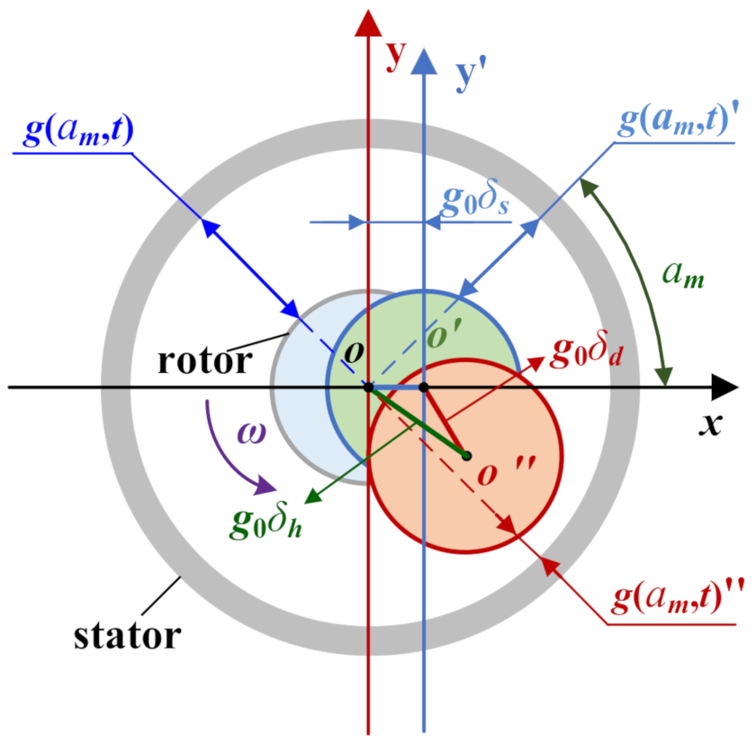
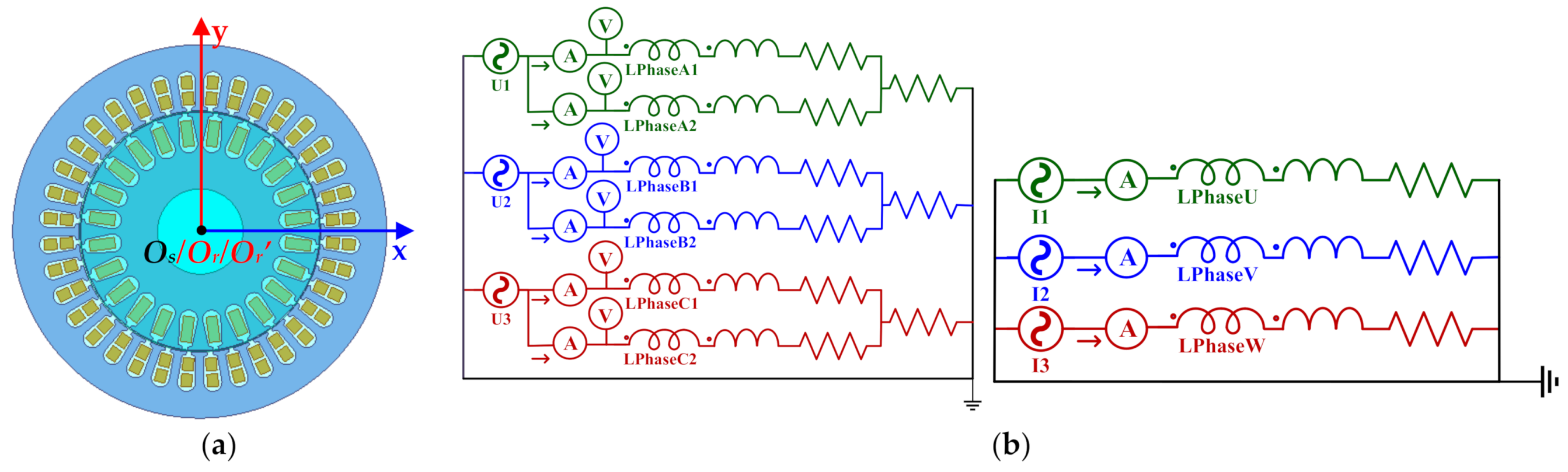
Theoretical Model

Magnetic flux density (MFD) can be obtained by multiplying the magnetomotive force (MMF) by the permeance per unit area (PPUA) as follows:
b α m , t = f α m , t Λ α m , t
where b is MFD, f is MMF, and Λ is PPUA.
The air-gap MMF in the spatial angle αm can be written as
f ( α m , t ) = f p ( α m , t ) + v f v ( α m , t ) + μ f μ ( α m , t )
where fp (αm, t), fv (αm, t), and fμ (αm, t) are the main wave composite MMF, the stator winding harmonic MMF, and the rotor winding harmonic MMF, respectively. In addition, p is the number of pole pairs of the main wave composite MMF. v and μ are the number of pole pairs of the stator and rotor winding tooth harmonic MMF, respectively.
The specific expression of each part of the MMF is
f p ( α m , t ) = F 0 cos ( p α m ω 1 t φ p ) f v ( α m , t ) = F v cos ( v α m ω 1 t φ v ) f μ ( α m , t ) = F μ cos ( μ α m ω μ t φ μ ) v = ± k 1 Z 1 + p , k 1 = 1 , 2 μ = ± k 2 Z 2 + p , k 2 = 1 , 2
where F0, Fv, and Fμ are the amplitude of the main wave composite MMF, the stator winding harmonic MMF, and the rotor winding harmonic MMF, respectively. φp is the initial phase angle of the main wave composite MMF. φv and φμ are the initial phase angles of the stator v and rotor μ subharmonic MMFs. ω1 is the angular frequency of the main wave synthesized MMF, and ωμ is the angular frequency of the rotor μ order harmonic MMF relative to the stator. Z1 is the number of stator slots, and Z2 is the number of rotor slots.
The ωμ can be expressed as
ω μ = ω 1 1 + k 2 Z 2 1 s / p
where s is the slip ratio of the DFIG.
The air-gap length affects the magnetic PPUA, which in turn affects the air-gap MFD. Firstly, a geometric model of the generator stator and rotor motion during eccentricity is established, and the expression of air-gap length is obtained, as indicated in Figure 1. Given that the stator and rotor cross-sectional edges are approximately ideal circles, and the shape and position of the stator and rotor do not alter in the axial direction, there is no axial eccentricity. According to the rotor movement characteristics, the eccentricity faults are divided into RSAGE, RDAGE, and RHAGE, as shown in Figure 1. In this article, RSAGE is the situation where O′ (O″) deviates from O, RDAGE is the case where O′ deviates from O (O″), and the numerals behind are offset distances (the unit is millimeter). RHAGE is the coexistence of both RSAGE and RDAGE (RHAGE0.1 = RSAGE0.1 + RDAGE0.1). Details are as follows:
(1)
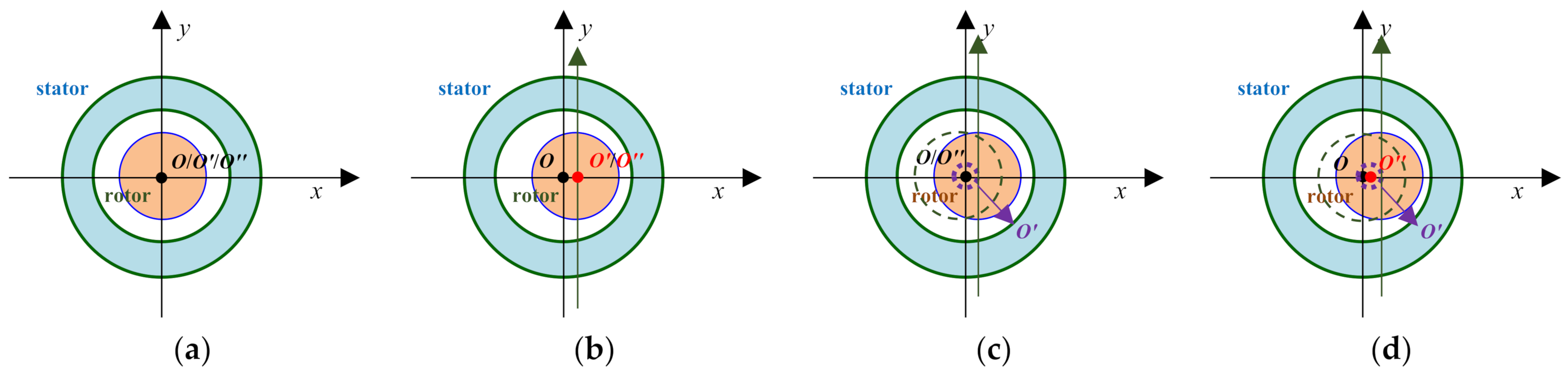
O, O′, and O″ coincide when there is no eccentricity;
(2)
In RSAGE, O′ coincides with O″ but not with O;
(3)
In RDAGE, O and O″ coincide but not with O′;
(4)
In RHAGE, O, O′, and O″ do not coincide.
Figure 1. Air-gap under the generator is RAGE.
Energies 15 06152 g001
O, O′, and O″ in different cases are shown in Figure 2.
PPUA should depend on the radial air-gap length, which is affected by RAGE. According to Figure 1, the radial air-gap length can be written as
g a m , t = g 0 normal g 0 ( 1 δ s cos α m ) RSAGE g 0 [ 1 δ d cos ( ω r t α m ) ] RDAGE g 0 [ 1 δ s cos α m δ d cos ( ω r t α m ) ] RHAGE
where g0 is the air-gap length in normal conditions, and αm is the circumferential angle of the air gap. δs and δd are the values of static eccentricity and dynamic eccentricity, respectively. ωr is the rotational frequency of the rotor under RDAGE.
Then, based on Equation (5), PPUA can be obtained as
Λ a m , t = μ 0 g a m , t Λ 0 + k 1 λ k 1 + k 2 λ k 2 + k 1 k 2 λ k 1 λ k 2 normal ( Λ 0 + k 1 λ k 1 + k 2 λ k 2 + k 1 k 2 λ k 1 λ k 2 ) ( 1 + δ s cos α m + δ s 2 cos 2 α m ) RSAGE ( Λ 0 + k 1 λ k 1 + k 2 λ k 2 + k 1 k 2 λ k 1 λ k 2 ) [ 1 + δ d cos ( ω r t α m ) ] RDAGE ( Λ 0 + k 1 λ k 1 + k 2 λ k 2 + k 1 k 2 λ k 1 λ k 2 ) [ 1 + δ s cos α m + δ d cos ( ω r t α m ) ] RHAGE
where Λ0 is the constant part of the air-gap permeance. λk1 is the harmonic permeance caused when the stator is slotted, and the rotor surface is smooth. λk2 is the harmonic permeance caused when the rotor is slotted, and the stator surface is smooth. λk1 λk2 is the harmonic permeance caused by a simultaneous slotting interaction of the stator and the rotor.
MFD can be obtained by feeding Equations (3) and (6) into Equation (1) as follows:
B α m , t = f α m , t Λ α m , t = F 0 Λ 0 cos p α m ω 1 t φ p + v F v Λ 0 cos v α m ω 1 t φ v + μ F μ Λ 0 cos μ α m ω μ t φ μ + k 1 F 0 Λ 0 λ k 1 2 cos v α m ω 1 t φ v + k 2 F 0 Λ 0 λ k 2 2 cos μ α m ω μ t φ μ normal F 0 Λ 0 cos p α m ω 1 t φ p + v F v Λ 0 cos v α m ω 1 t φ v + μ F μ Λ 0 cos μ α m ω μ t φ μ + k 1 F 0 Λ 0 λ k 1 2 cos v α m ω 1 t φ v + k 2 F 0 Λ 0 λ k 2 2 cos μ α m ω μ t φ μ + F 0 Λ 0 δ s 2 cos p ± 1 α m ω 1 t φ p + v F v Λ 0 δ s 2 cos v ± 1 α m ω 1 t φ v + μ F μ Λ 0 δ s 2 cos μ ± 1 α m ω μ t φ μ + k 1 F 0 Λ 0 λ k 1 δ s 2 cos v ± 1 α m ω 1 t φ v + k 2 F 0 Λ 0 λ k 2 δ s 2 cos μ ± 1 α m ω μ t φ μ RSAGE F 0 Λ 0 cos p α m ω 1 t φ p + v F v Λ 0 cos v α m ω 1 t φ v + μ F μ Λ 0 cos μ α m ω μ t φ μ + k 1 F 0 Λ 0 λ k 1 2 cos v α m ω 1 t φ v + k 2 F 0 Λ 0 λ k 2 2 cos μ α m ω μ t φ μ + F 0 Λ 0 δ d 2 cos p ± 1 α m ( ω 1 ± ω r ) t φ p + v F v Λ 0 δ d 2 cos v ± 1 α m ( ω 1 ± ω r ) t φ v + μ F μ Λ 0 δ d 2 cos μ ± 1 α m ( ω μ ± ω r ) t φ μ + k 1 F 0 Λ 0 λ k 1 δ d 2 cos v ± 1 α m ( ω 1 ± ω r ) t φ v + k 2 F 0 Λ 0 λ k 2 δ d 2 cos μ ± 1 α m ( ω μ ± ω r ) t φ μ RDAGE F 0 Λ 0 cos p α m ω 1 t φ p + v F v Λ 0 cos v α m ω 1 t φ v + μ F μ Λ 0 cos μ α m ω μ t φ μ + k 1 F 0 Λ 0 λ k 1 2 cos v α m ω 1 t φ v + k 2 F 0 Λ 0 λ k 2 2 cos μ α m ω μ t φ μ + F 0 Λ 0 δ s 2 cos p ± 1 α m ω 1 t φ p + v F v Λ 0 δ s 2 cos v ± 1 α m ω 1 t φ v + μ F μ Λ 0 δ s 2 cos μ ± 1 α m ω μ t φ μ + k 1 F 0 Λ 0 λ k 1 δ s 2 cos v ± 1 α m ω 1 t φ v + k 2 F 0 Λ 0 λ k 2 δ s 2 cos μ ± 1 α m ω μ t φ μ + F 0 Λ 0 δ d 2 cos p ± 1 α m ( ω 1 ± ω r ) t φ p + v F v Λ 0 δ d 2 cos v ± 1 α m ( ω 1 ± ω r ) t φ v + μ F μ Λ 0 δ d 2 cos μ ± 1 α m ( ω μ ± ω r ) t φ μ + k 1 F 0 Λ 0 λ k 1 δ d 2 cos v ± 1 α m ( ω 1 ± ω r ) t φ v + k 2 F 0 Λ 0 λ k 2 δ d 2 cos μ ± 1 α m ( ω μ ± ω r ) t φ μ RHAGE
According to Equation (7), RSAGE introduces extra MFD harmonic components, whose spatial coefficients are p ± 1, v ± 1, and μ ± 1, and the corresponding frequencies are ω1, ω1, and ωμ. The stator winding adopts a double Y-shaped connection, and each phase has two parallel branches, as shown in Figure 3.
In Figure 3, U1U2 is the two branches of the A-phase winding. V1V2 is the two branches of the B-phase winding. W1W2 is the two branches of the C-phase winding.
Using the knowledge of electrical machinery, the high order and small amplitude harmonics can be ignored, and the instantaneous value of the induced electromotive force of a single parallel branch of the generator stator winding is determined as
E ( α m , t ) = q w c k w 1 b ( α m , t ) l v = q w c k w 1 b ( α m , t ) l ( 2 τ f ) = 2 q w c k w 1 τ l f Λ 0 × F 0 cos p α m ω 1 t φ p + v F v cos v α m ω 1 t φ v + μ F μ cos μ α m ω μ t φ μ normal F 0 cos p α m ω 1 t φ p + v F v cos v α m ω 1 t φ v + μ F μ cos μ α m ω μ t φ μ + F 0 δ s 2 cos p ± 1 α m ω 1 t φ p + v F v δ s 2 cos v ± 1 α m ω 1 t φ v + μ F μ δ s 2 cos μ ± 1 α m ω μ t φ μ RSAGE F 0 cos p α m ω 1 t φ p + v F v cos v α m ω 1 t φ v + μ F μ cos μ α m ω μ t φ μ + F 0 δ d 2 cos p ± 1 α m ( ω 1 ± ω r ) t φ p + v F v δ d 2 cos v ± 1 α m ( ω 1 ± ω r ) t φ v + μ F μ δ d 2 cos μ ± 1 α m ( ω μ ± ω r ) t φ μ RDAGE F 0 cos p α m ω 1 t φ p + v F v cos v α m ω 1 t φ v + μ F μ cos μ α m ω μ t φ μ + F 0 δ s 2 cos p ± 1 α m ω 1 t φ p + v F v δ s 2 cos v ± 1 α m ω 1 t φ v + μ F μ δ s 2 cos μ ± 1 α m ω μ t φ μ + F 0 δ d 2 cos p ± 1 α m ( ω 1 ± ω r ) t φ p + v F v δ d 2 cos v ± 1 α m ( ω 1 ± ω r ) t φ v + μ F μ δ d 2 cos μ ± 1 α m ( ω μ ± ω r ) t φ μ RHAGE
where f is the mechanical rotation frequency of the rotor. l is the air-gap length. q is the number of slots per pole per phase. τ is the pole pitch. wc is the number of turns of a single coil. kw1 is the fundamental winding factor, the expression of which is
k w 1 = k y 1 × k q 1 = sin 90 ° × y / τ × sin q α 1 / 2 / q sin α 1 / 2
In Equation (9), ky1 is the fundamental wave pitch factor, kq1 is the fundamental wave distribution factor, α1 is the slot angle, and y is the stator winding pitch.
The corresponding sides of the two parallel branches of the generator have a certain law in the spatial distribution. The equivalent circuit of the parallel branch of the A-phase stator winding can be drawn as shown in Figure 4.
Where R1, R2, L1, and L2 are the resistance and self-inductance of two parallel branches of the A-phase, respectively. M1 and M2 are the mutual inductances of each branch and other branches, respectively. I1 and I2 are the currents corresponding to the two branches, Ic is the circulating current.
The induced electromotive force of the two branches can be expressed as
E a 1 ( α m , t ) = 2 q w c k w 1 τ l f Λ 0 = F 0 cos p α m ω 1 t φ p + v F v cos v α m ω 1 t φ v + μ F μ cos μ α m ω μ t φ μ E a 2 ( α m , t ) = 2 q w c k w 1 τ l f Λ 0 = F 0 cos p ( α m + π ) ω 1 t φ p + v F v cos v ( α m + π ) ω 1 t φ v + μ F μ cos μ ( α m + π ) ω μ t φ μ normal E a 1 ( α m , t ) = 2 q w c k w 1 τ l f Λ 0 = F 0 cos p α m ω 1 t φ p + v F v cos v α m ω 1 t φ v + μ F μ cos μ α m ω μ t φ μ + F 0 δ s 2 cos p ± 1 α m ω 1 t φ p + v F v δ s 2 cos v ± 1 α m ω 1 t φ v + μ F μ δ s 2 cos μ ± 1 α m ω μ t φ μ E a 2 ( α m , t ) = 2 q w c k w 1 τ l f Λ 0 = F 0 cos p ( α m + π ) ω 1 t φ p + v F v cos v ( α m + π ) ω 1 t φ v + μ F μ cos μ ( α m + π ) ω μ t φ μ + F 0 δ s 2 cos p ± 1 ( α m + π ) ω 1 t φ p + v F v δ s 2 cos v ± 1 ( α m + π ) ω 1 t φ v + μ F μ δ s 2 cos μ ± 1 ( α m + π ) ω μ t φ μ RSAGE E a 1 ( α m , t ) = 2 q w c k w 1 τ l f Λ 0 = F 0 cos p α m ω 1 t φ p + v F v cos v α m ω 1 t φ v + μ F μ cos μ α m ω μ t φ μ + F 0 δ d 2 cos p ± 1 α m ( ω 1 ± ω r ) t φ p + v F v δ d 2 cos v ± 1 α m ( ω 1 ± ω r ) t φ v + μ F μ δ d 2 cos μ ± 1 α m ( ω μ ± ω r ) t φ μ E a 2 ( α m , t ) = 2 q w c k w 1 τ l f Λ 0 = F 0 cos p ( α m + π ) ω 1 t φ p + v F v cos v ( α m + π ) ω 1 t φ v + μ F μ cos μ ( α m + π ) ω μ t φ μ + F 0 δ d 2 cos p ± 1 ( α m + π ) ( ω 1 ± ω r ) t φ p + v F v δ d 2 cos v ± 1 ( α m + π ) ( ω 1 ± ω r ) t φ v + μ F μ δ d 2 cos μ ± 1 ( α m + π ) ( ω μ ± ω r ) t φ μ RDAGE E a 1 ( α m , t ) = 2 q w c k w 1 τ l f Λ 0 = F 0 cos p α m ω 1 t φ p + v F v cos v α m ω 1 t φ v + μ F μ cos μ α m ω μ t φ μ + F 0 δ s 2 cos p ± 1 α m ω 1 t φ p + v F v δ s 2 cos v ± 1 α m ω 1 t φ v + μ F μ δ s 2 cos μ ± 1 α m ω μ t φ μ + F 0 δ d 2 cos p ± 1 α m ( ω 1 ± ω r ) t φ p + v F v δ d 2 cos v ± 1 α m ( ω 1 ± ω r ) t φ v + μ F μ δ d 2 cos μ ± 1 α m ( ω μ ± ω r ) t φ μ E a 2 ( α m , t ) = 2 q w c k w 1 τ l f Λ 0 = F 0 cos p ( α m + π ) ω 1 t φ p + v F v cos v ( α m + π ) ω 1 t φ v + μ F μ cos μ ( α m + π ) ω μ t φ μ + F 0 δ s 2 cos p ± 1 ( α m + π ) ω 1 t φ p + v F v δ s 2 cos v ± 1 ( α m + π ) ω 1 t φ v + μ F μ δ s 2 cos μ ± 1 ( α m + π ) ω μ t φ μ + F 0 δ d 2 cos p ± 1 ( α m + π ) ( ω 1 ± ω r ) t φ p + v F v δ d 2 cos v ± 1 ( α m + π ) ( ω 1 ± ω r ) t φ v + μ F μ δ d 2 cos μ ± 1 ( α m + π ) ( ω μ ± ω r ) t φ μ RHAGE
where wa1 = wa2 = wc, R1 = R2, L1 = L2, I1 = I2, and E1 = E2. Therefore, the CCPB of the stator can be expressed as
U a 12 ( α m , t ) = E a 1 ( α m , t ) + j ω L a 1 I a 1 + R a 1 I a 1 + j ω i M a 1 i I i j ω k M a 2 k I k R a 2 I a 2 j ω L a 2 I a 2 E a 2 ( α m , t )
Feeding Equation (10) into Equation (11), we can obtain the potential difference between the two parallel branches of the generator stator winding before and after SAGE, which can be expressed as
U a 12 α m , t = 2 q w c k w 1 τ l f Λ 0 × 0 normal F 0 δ s cos ( p ± 1 ) α m ω 1 t φ p + v F v δ s cos ( v ± 1 ) α m ω 1 t φ v + μ F μ δ s cos ( μ ± 1 ) α m ω μ t φ μ RSAGE F 0 δ d cos ( p ± 1 ) α m ω 1 ± ω r t φ p + v F v δ d cos ( v ± 1 ) α m ω 1 ± ω r t φ v + μ F μ δ d cos ( μ ± 1 ) α m ω μ ± ω r t φ μ RDAGE F 0 δ s cos ( p ± 1 ) α m ω 1 t φ p + v F v δ s cos ( v ± 1 ) α m ω 1 t φ v + μ F μ δ s cos ( μ ± 1 ) α m ω μ t φ μ + F 0 δ d cos ( p ± 1 ) α m ω 1 ± ω r t φ p + v F v δ d cos ( v ± 1 ) α m ω 1 ± ω r t φ v + μ F μ δ d cos ( μ ± 1 ) α m ω μ ± ω r t φ μ RHAGE
For the sake of analyzing the effect on CCPB characteristics before and after the SAGE fault, the components introduced in different air-gap eccentricity faults were classified according to the same frequency, as shown in Table 2.
According to Table 2 and Equation (12), there is no CCPB of the stator winding under normal operation. The CCPB of the stator winding appears after the occurrence of RAGE. It is mainly composed of three parts: The first part is caused by an additional magnetic field with a pole pair number of p ± 1 and a corresponding frequency of ω1 that will be introduced by the static eccentricity fault. The second part is caused by an additional magnetic field with a pole pair number of v ± 1 and a corresponding frequency of ω1 caused by the static eccentricity fault. The third part is caused by the additional magnetic field with a pole pair number of μ ± 1 and a corresponding frequency of ωμ caused by the static eccentricity fault. RDAGE also introduces new frequency components compared with normal conditions, which are f1 ± fr and fu ± fr, respectively. The f1 ± fr frequency component includes magnetic pole log numbers of p ± 1 and v ± 1, and the fu ± fr frequency component includes a magnetic polar log of μ ± 1. The RHAGE frequency ingredient is an overlay of RSAGE and RDAGE.
In order to clarify the influence of the variables in MFD and CCPB expressions, the changes in the frequency components and amplitude of the MFD and CCPB before and after the different types of eccentricity are listed in Table 3.
According to Table 3, RSAGE only changes the amplitude of the MFD and CCPB without changing their frequency components. Conversely, RDAGE and RHAGE faults change the frequency components and amplitude of the MFD and CCPB at the same time. In addition, with an increase in the eccentric volume, the amplitude of the frequency component of the MFD (the side of the decrease in air gap) and CCPB also increases.

3. FEA and Experiment Validation

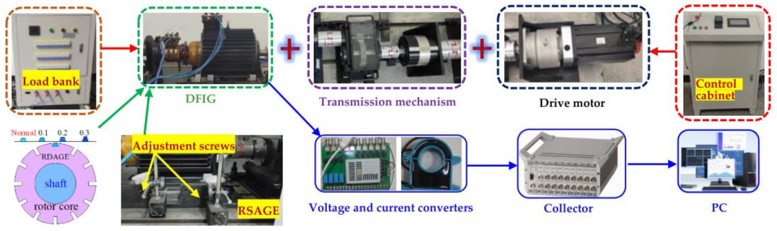
3.1. FEA and Experiment Setup

In this study, FEA and experiments were performed on a double-fed asynchronous wind turbine with two pairs of poles. The main parameters of the generator are shown in Table 4. The simulation model established by using ANSYS Electronic is shown in Figure 5, and the experimental units are shown in Figure 6.
According to the working principle of the ANSYS Electronics ACT, the following assumptions can be made: The origin of the coordinate axis (the geometric center of the stator) is defined as Os, and the center of rotation of the rotor is defined as Or. The rotor rotates at an angular velocity ω around Or. In RDAGE, the rotation of the rotor also simultaneously occurs around a point with the angular velocity ω, so the center of the rotational trajectory of Or is defined as Or. The RSAGE, RDAGE, and RHAGE can be obtained by combining Os, Or, and Or’. In addition, the eccentricity fault level was set to 0.1, 0.2, and 0.3 in each case. In this paper, the positive direction of the X-axis was chosen as the eccentricity direction.
Since the air-gap eccentricity fault is a mechanical fault, it has no effect on the external circuit. Therefore, all the external circuits used in this paper are shown in Figure 5b.
The actual speed of the simulation model of this paper is 1470 rpm, that is, the slip rate s= (1500 − 1470)/1500 = 2%. Therefore, the value of fu = 540/640 (k2 = ±1). This article only lists the frequency components for which the absolute value of k2 is less than 2.
The overall structure of the generator is shown in Figure 6. The degree of the RSAGE of the generator was achieved by the radial displacement of the stator. The radial displacement of the stator was controlled by adjusting four screws on the front and back, and the specific offset distance was measured by dial indicators, as indicated in Figure 6. In addition, the degree of RDAGE was adjusted by exchanging the wedges embedded in the grooves of the rotor core, as seen in Figure 6. Specifically, normal wedges flushed with the circumferential surface of the rotor, and 0.1 mm, 0.2 mm, and 0.3 mm wedges above the circumferential surface were prepared in advance; the degree of the RDAGE eccentricity increased as the height of the replacement wedges increased. The external equipment of the generator (control cabinet and load bank) is shown in Figure 6. The experiments and FEA calculations had the same parameter settings and were conducted four times in the following order:
(1)
Common normal condition;
(2)
RSAGE of 0.1, 0.2, and 0.3 mm;
(3)
RDAGE of 0.1, 0.2, and 0.3 mm;
(4)
RHAGE of 0.1, 0.2, and 0.3 mm.

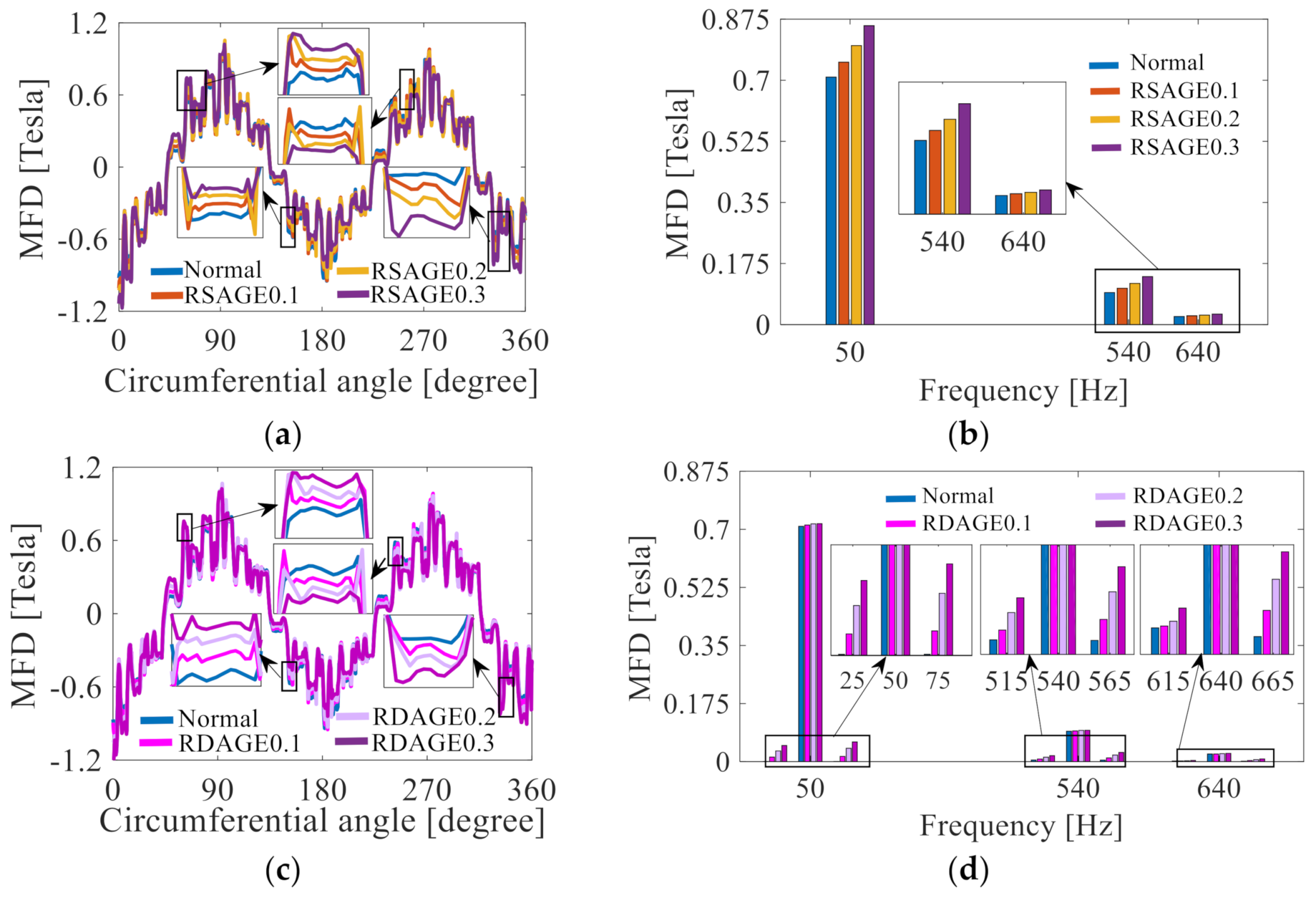
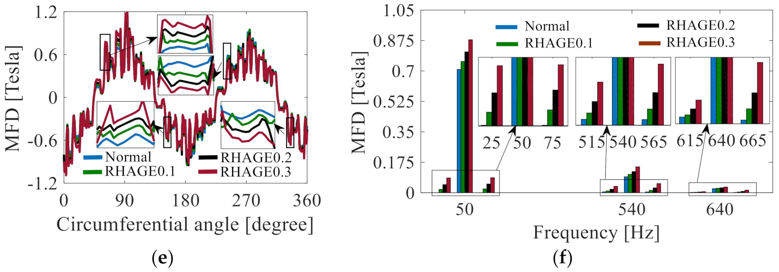
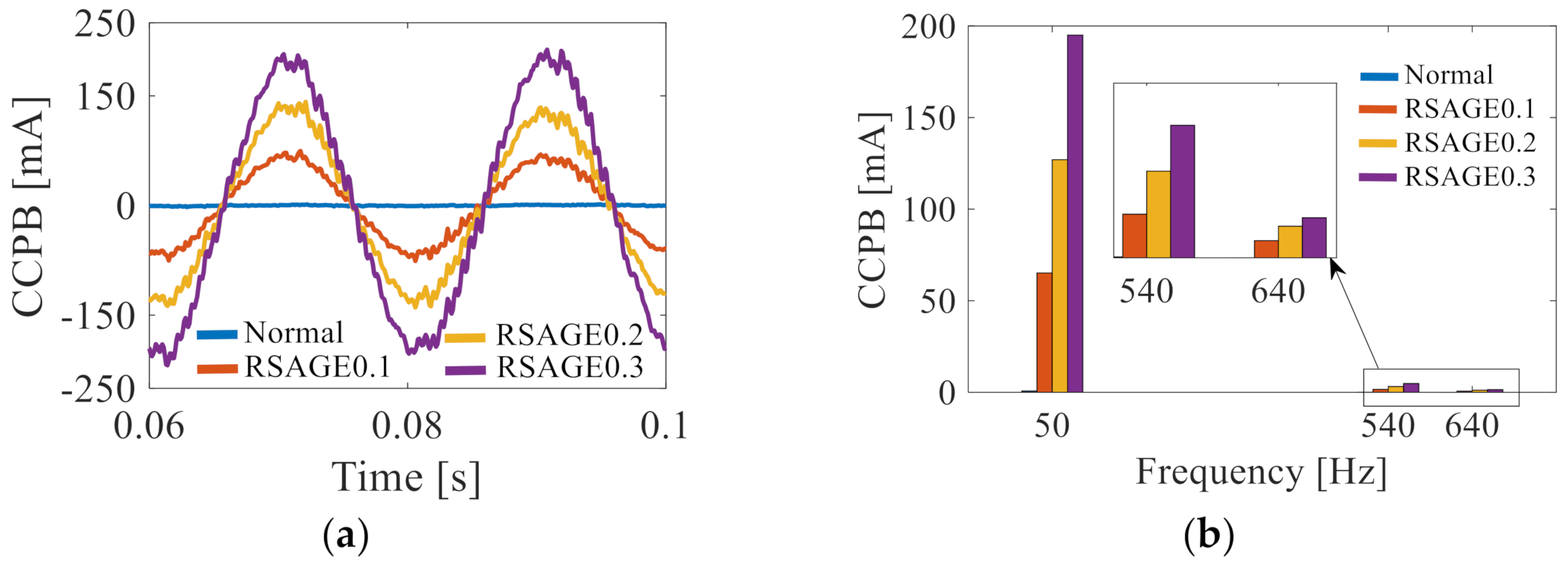
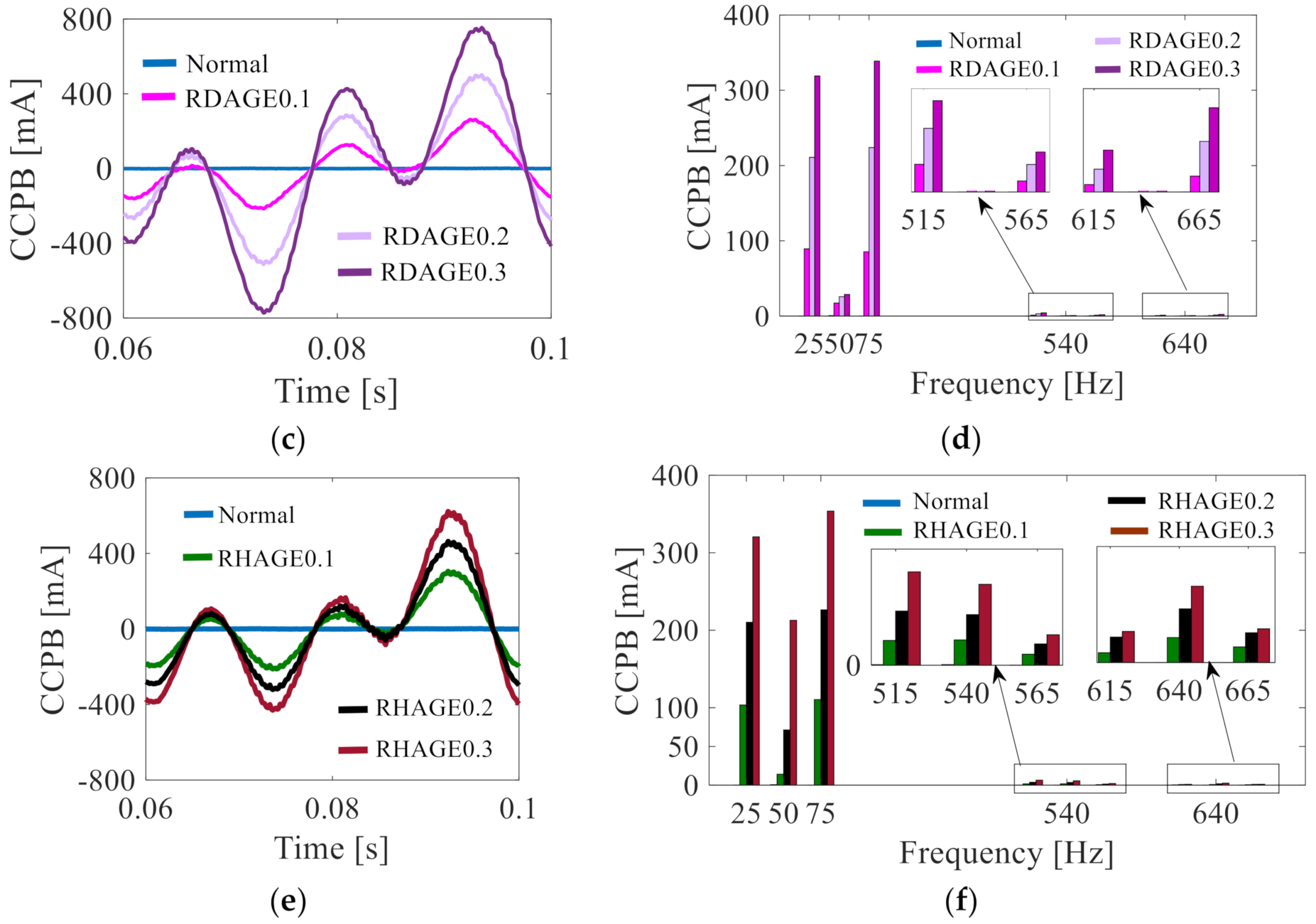
3.2. FEA Results’ Discussion

The air-gap MFD results in different cases are shown in Figure 7 and Table 5. The analysis of the simulation time domain results revealed that as the extent of the degree of eccentricity increased, the amplitude of the local magnetic field density of the air gap increased.
The occurrence of RAGE changed the frequency component of the MFD. The RSAGE condition did not change the composition of the frequency components and only affected the size of the amplitude, as shown in Figure 7a,b. However, RDAGE resulted in f1 ± fr (25/75) fu ± fr (515/564, k2 = ±1) for the MFD, as shown in Figure 7c,d. The result of RHAGE was the superposition of RSAGE and RDAGE. Therefore, the frequency components of RHAGE were consistent with RDAGE, as shown in Figure 7e,f and Table 5. The amplitude of these frequency components was enlarged with an increase in eccentricity.
According to the setting of the simulation model speed, one cycle of the DFIG was approximately 40 ms, and the CCPB in this article used a stable waveform of 60–100 ms, as shown in Figure 8 and Table 6. According to Figure 8a–e, the amplitude of the CCPB was close to zero under normal conditions. However, the amplitude of the CCPB increased with the development of RAGE, as indicated in Figure 8 and Table 6.
From Figure 8b,d,f, it can be derived that the CCPB frequency components f1 (50) and fu (540/640) were induced when RSAGE occurred. Similarly, RDAGE yielded f1 ± fr (25/75) and fu ± fr (515/565/615/665, k2 = ±1) for the CCPB frequency components. The frequency components of the CCPB during RHAGR were the superposition of RSAGR and RDAGR. Generally, with the increase in RAGE, the amplitude of each component also increased. The frequency component calculated by using FEA was consistent with the theoretical analysis.

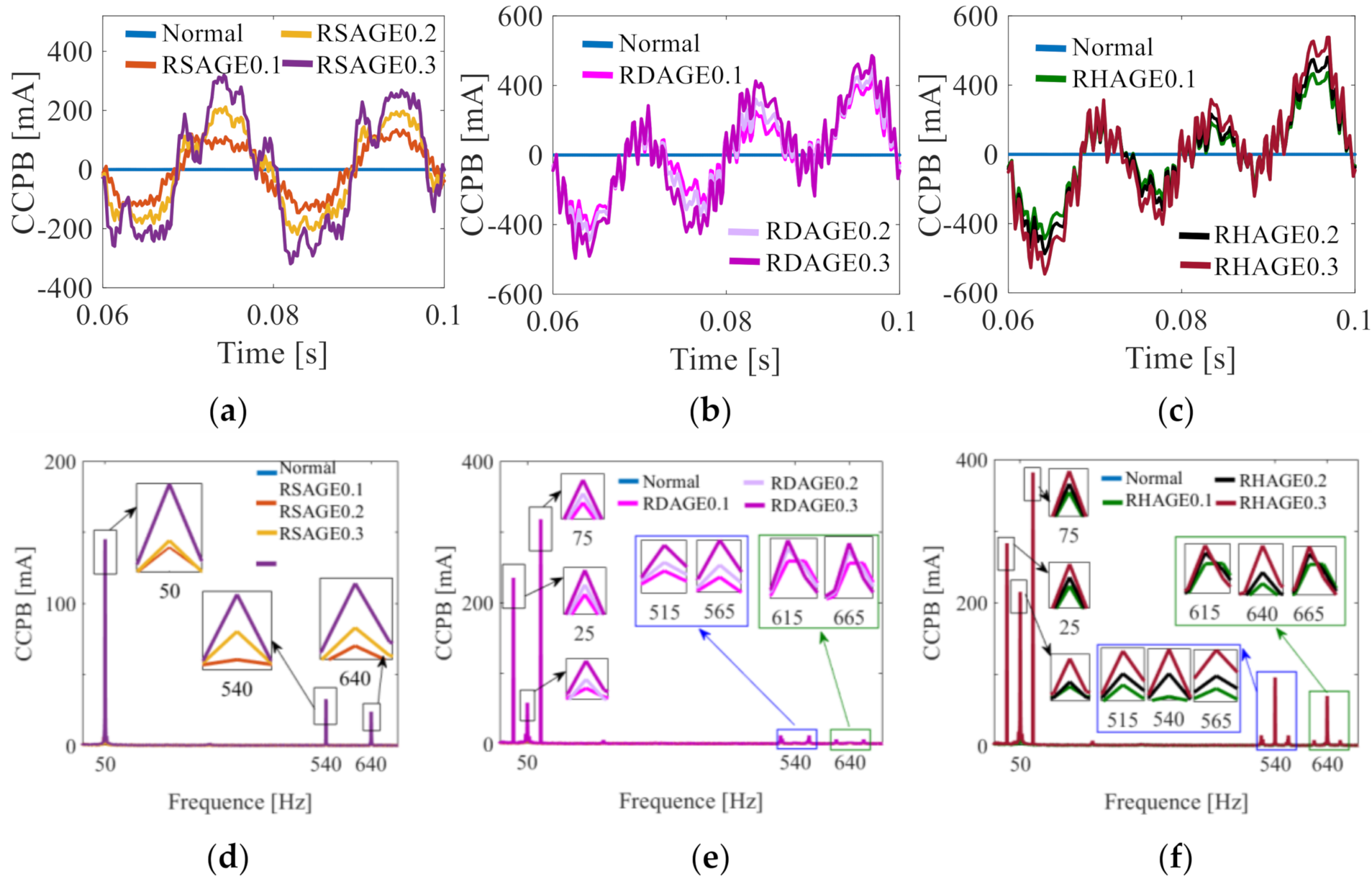
3.3. Experiment Results’ Discussion

The experimental data were obtained on the DFIG experimental unit, as indicated in Figure 6. Regardless of the branches of the A-phase, B-phase, or C-phase, it can be seen that the degree of eccentricity caused an increase in the amplitude of the CCPB, as shown in Figure 9a–c. The change in frequency components also changed the curves’ shape. The frequency components of each case are shown in Figure 9. More details can be seen in Table 7.
According to Figure 9d–f, after RSAGR, the components with frequencies f1 (50) and fu (540/640) appeared in the CCPB. However, RDAGE yielded f1 ± fr (25/75) and fu ± fr (515/565/615/665, k2 = ±1) for the CCPB. Additionally, RHAGR was the superposition of RSAGR and RDAGR, as shown in Table 7. At this point, the theoretical derivation, FEA conclusions, and experimental results were basically consistent, thus, the model was well-verified.

4. Conclusions

In this paper, we studied the CCPB with RSAGE, RDAGE, and RHAGE faults in a DFIG, derived the corresponding theoretical formula of the MFD and CCPB, and established a finite element model for simulation. Later, experimental verification was carried out on the fault simulation. The theoretical derivation, finite element simulation results, and experimental results were consistent with each other. The conclusions are as follows:
(1) For the MFD, the increase in eccentricity resulted in a gradual increase in the air-gap magnetic field density. Different kinds of air-gap eccentricity changed the composition of the MFD. For RSAGE, the frequency component was the same as normal. For RDAGE and RHAGE, the frequency component of f1 ± fr, fu ± fr was newly present relative to the normal condition. The increase in eccentricity would cause an increase in the values of the frequency components.
(2) For the CCPB, the change in eccentric species caused a change in the shape of the time domain curve, which was caused by changes in the frequency components. At the same time, the increase in eccentricity caused a significant increase in the CCPB. Similarly, different kinds of air-gap eccentric also changed the composition of CCPB. For RSAGE, the frequency component had new frequency components of f1 and fμ compared with normal conditions. For RDAGE, the frequency components of f1 ± fr and fu ± fr were newly present relative to the normal condition. For RHAGE, the frequency components at RSAGE and RDAGE appeared at the same time. The increase in eccentricity would result in an increase in the amplitude of the frequency components.

Author Contributions

Conceptualization, Y.-L.H., X.-A.L. and M.-X.X.; methodology, Y.-L.H., W.-J.Z. and M.-X.X.; software, Y.-L.H. and X.-A.L.; validation, D.-R.D. and W.Z.; formal analysis, Y.-L.H.; investigation, Y.-L.H.; resources, Y.-L.H.; data curation, Y.-L.H. and S.-T.W.; writing—original draft preparation, Y.-L.H., X.-A.L., W.-J.Z., D.-R.D., M.-X.X., W.Z. and D.G.; writing—review and editing, Y.-L.H., X.-A.L. and D.G.; visualization, D.-R.D., M.-X.X. and W.Z.; supervision, Y.-L.H. and D.G.; project administration, Y.-L.H. and W.Z.; funding acquisition, Y.-L.H. and G.-J.T. All authors have read and agreed to the published version of the manuscript.

Funding

This research was funded by the National Natural Science Foundation of China (No.52177042), in part by the Chinese Fundamental Research Funds for the Central Universities (2018YQ03), in part by the Hebei Provincial Top Youth Talent Support Program ((2018)-27), and in part by the Natural Science Foundation of Hebei Province of China (E2020502031).

Institutional Review Board Statement

Not applicable.

Informed Consent Statement

Not applicable.

Data Availability Statement

Not applicable.

Acknowledgments

This work was supported by the Hebei Key Laboratory of Electric Machinery Health Maintenance and Failure Prevention, North China Electric Power University, Baoding, China.

Conflicts of Interest

The authors declare no conflict of interest.

Abbreviations

The following abbreviations are used in this manuscript:
DFIGDoubly fed induction generator
RAGERadial air-gap eccentricity
RSAGERadial static air-gap eccentricity
RDAGERadial dynamic air-gap eccentricity
RHAGERadial hybrid air-gap eccentricity
CCPBCirculating current inside parallel branches
MFDMagnetic flux density
MMFMagnetomotive force
PPUAPermeance per unit area
FEAFinite element analysis

References

  1. Energy-Wind Energy. New Wind Energy Research from Rzeszow University of Technology Outlined (Taxonomic Analysis of the Diversity in the Level of Wind Energy Development in European Union Countries). Energy Weekly News 2020, 876. [Google Scholar]
  2. Reja, R.K.; Amin, R.; Tasneem, Z.; Ali, M.F.; Islam, M.R.; Saha, D.K.; Badal, F.R.; Ahamed, M.H.; Moyeen, S.L.; Das, S.K. A review of the evaluation of urban wind resources: Challenges and per-spectives. Energy Build. 2022, 257, 111781. [Google Scholar] [CrossRef]
  3. Dinh, Q.V.; Doan, Q.V.; Ngo-Duc, T.; Duc, N.D. Offshore wind resource in the context of global climate change over a tropical area. Appl. Energy 2022, 308, 118369. [Google Scholar] [CrossRef]
  4. Xiahou, K.; Lin, X.; Liu, Y.; Wu, Q.H. Robust Rotor-Current Sensor less Control of Doubly Fed Induction Genera-tors. IEEE Trans. Energy Convers. 2018, 33, 897–899. [Google Scholar] [CrossRef]
  5. Han, J.; Liu, Z.; Liang, N. Nonlinear Adaptive Robust Control Strategy of Doubly Fed Induction Generator Based on Virtual Synchronous Generator. IEEE Access 2020, 8, 159887–159896. [Google Scholar] [CrossRef]
  6. He, Y.L.; Zhang, Z.J.; Tao, W.Q.; Wang, X.L.; Gerada, D.; Gerada, C.; Gao, P. A New External Search Coil Based Method to Detect Detailed Static Air-Gap Eccentricity Position in Nonsalient Pole Synchronous Generators. IEEE Trans. Ind. Electron. 2021, 68, 7535–7544. [Google Scholar] [CrossRef]
  7. Bruzzese, C.; Joksimovic, G. Harmonic Signatures of Static Eccentricities in the Stator Voltages and in the Rotor Current of No-Load Salient-Pole Synchronous Generators. IEEE Trans. Ind. Electron. 2011, 58, 1606–1624. [Google Scholar] [CrossRef]
  8. He, Y.L.; Xu, M.X.; Xiong, J.; Sun, Y.X.; Wang, X.L.; Gerada, D.; Vakil, G. Effect of 3D Unidirectional and Hybrid SAGE on Electromagnetic Torque Fluctuation Characteristics in Synchronous Generator. IEEE Access 2019, 7, 100813–100823. [Google Scholar] [CrossRef]
  9. Da, Y.; Shi, X.; Krishnamurthy, M. A New Approach to Fault Diagnostics for Permanent Magnet Synchronous Machines Using Electromagnetic Signature Analysis. IEEE Trans. Power Electron. 2013, 28, 4104–4112. [Google Scholar] [CrossRef]
  10. Attestog, S.; Khang, H.V.; Robbersmyr, K.G. Detecting Eccentricity and Demagnetization Fault of Permanent Magnet Synchronous Generators in Transient State. In Proceedings of the 2019 22nd International Conference on Electrical Machines and Systems (ICEMS), Harbin, China, 11–14 August 2019; pp. 1–5. [Google Scholar]
  11. Dorrell, D.G.; Salah, A.; Guo, Y. The Detection and Suppression of Unbalanced Magnetic Pull in Wound Rotor Induction Motors Using Pole-Specific Search Coils and Auxiliary Windings. IEEE Trans. Ind. Appl. 2017, 53, 2066–2076. [Google Scholar] [CrossRef]
  12. Ehya, H.; Nysveen, A.; Nilssen, R.; Liu, Y. Static and dynamic eccentricity fault diagnosis of large salient pole synchronous generators by means of external magnetic field. IET Electr. Power Appl. 2021, 15, 890–902. [Google Scholar] [CrossRef]
  13. Li, J.; Wang, X.-B.; Luo, Z.; Chen, H.; Yang, Z.-X. Diagnosis of the Mixed Eccentricity Fault in Interior Permanent Magnet Synchronous Motors based on the Open-Circuit External Field. In Proceedings of the 2022 5th International Conference on Energy, Electrical and Power Engineering (CEEPE), Chongqing, China, 22–24 April 2022; pp. 484–489. [Google Scholar]
  14. Wan, S.; He, Y. Investigation on stator and rotor vibration characteristics of turbo-generator under air gap eccentricity fault. Trans. Can. Soc. Mech. Eng. 2011, 35, 161–176. [Google Scholar] [CrossRef]
  15. Zarko, D.; Ban, D.; Vazdar, I.; Jarica, V. Calculation of Unbalanced Magnetic Pull in a Salient-Pole Synchronous Generator Using Finite-Element Method and Measured Shaft Orbit. IEEE Trans. Ind. Electron. 2012, 59, 2536–2549. [Google Scholar] [CrossRef]
  16. He, Y.L.; Sun, Y.X.; Xu, M.X.; Wang, X.L.; Wu, Y.C.; Vakil, G.; Gerada, D.; Gerada, C. Rotor UMP characteristics and vibration properties in synchronous generator due to 3D static air-gap eccentricity faults. IET Electr. Power Appl. 2020, 14, 961–971. [Google Scholar] [CrossRef]
  17. He, Y.-L.; Wang, Y.; Jiang, H.-C.; Gao, P.; Yuan, X.-H.; Gerada, D.; Liu, X.-Y. A Novel Universal Model Considering SAGE for MFD-Based Faulty Property Analysis Under RISC in Synchronous Generators. IEEE Trans. Ind. Electron. 2022, 69, 7415–7427. [Google Scholar] [CrossRef]
  18. Andriamalala, R.N.; Razik, H.; Baghli, L.; Sargos, F. Eccentricity Fault Diagnosis of a Dual-Stator Winding Induction Machine Drive Considering the Slotting Effects. IEEE Trans. Ind. Electron. 2008, 55, 4238–4251. [Google Scholar] [CrossRef]
  19. Faiz, J.; Ebrahimi, B.M.; Akin, B.; Toliyat, H.A. Comprehensive Eccentricity Fault Diagnosis in Induction Motors Using Finite Element Method. IEEE Trans. Magn. 2009, 45, 1764–1767. [Google Scholar] [CrossRef]
  20. Bruzzese, C. Diagnosis of Eccentric Rotor in Synchronous Machines by Analysis of Split-Phase Currents—Part II: Experimental Analysis. IEEE Trans. Ind. Electron. 2014, 61, 4206–4216. [Google Scholar] [CrossRef]
  21. Bruzzese, C.; Trentini, F.; Santini, E.; Joksimović, G. Sequence Circuit-Based Modeling of a Doubly Fed Induction Wind Generator for Eccentricity Diagnosis by Split-Phase Current Signature Analysis. In Proceedings of the 2018 5th International Symposium on Environment-Friendly Energies and Applications (EFEA), Rome, Italy, 24–26 September 2018; pp. 1–8. [Google Scholar]
  22. Gong, X.; Qiao, W. Current-Based Mechanical Fault Detection for Direct-Drive Wind Turbines via Synchronous Sampling and Impulse Detection. IEEE Trans. Ind. Electron. 2015, 62, 1693–1702. [Google Scholar] [CrossRef]
  23. Salah, A.A.; Dorrell, D.G. Operating Induction Machine in DFIG Mode Including Rotor Asymmetry. In Proceedings of the 2019 Southern African Universities Power Engineering Conference/Robotics and Mechatronics/Pattern Recognition Association of South Africa (SAUPEC/RobMech/PRASA), Bloemfontein, South Africa, 28–30 January 2019; pp. 469–474. [Google Scholar]
  24. Hamatwi, E.; Barendse, P.; Khan, A. Development of a Test Rig for Fault Studies on a scaled-down DFIG. In Proceedings of the 2021 IEEE Energy Conversion Congress and Exposition (ECCE), Vancouver, BC, Canada, 10–14 October 2021; pp. 3805–3812. [Google Scholar]
  25. Foggia, A.; Torlay, J.-E.; Corenwinder, C.; Audoli, A.; Herigault, J. Circulating current analysis in the parallel-connected windings of synchronous generators under abnormal operating conditions. In Proceedings of the IEEE International Electric Machines and Drives Conference’ IEMDC’99’ Proceedings (Cat. No.99EX272), Seattle, WA, USA, 9–12 May 1999; pp. 634–636. [Google Scholar]
  26. Rodriguez, P.; Rzeszucinski, P.; Sulowicz, M.; Disselnkoetter, R.; Ahrend, U.; Pinto, C.T.; Ottewill, J.R.; Wildermuth, S. Stator circulating currents as media of fault detection in synchronous motors. In Proceedings of the 2013 9th IEEE International Symposium on Diagnostics for Electric Machines, Power Electronics and Drives (SDEMPED), Valencia, Spain, 27–30 August 2013; pp. 207–214. [Google Scholar]
  27. Shuting, W.; Yuling, H. Analysis on stator circulating current characteristics of turbo-generator under eccentric faults. In Proceedings of the 2009 IEEE 6th International Power Electronics and Motion Control Conference, Wuhan, China, 17–20 May 2009; pp. 2062–2067. [Google Scholar]
  28. Mafruddin, M.M.; Suwarno, S.; AbuSiada, A. Finite Element Simulation of a 126 MW Salient Pole Synchronous Generator with Rotor Eccentricity. In Proceedings of the 2019 2nd International Conference on High Voltage Engineering and Power Systems (ICH-VEPS), Denpasar, Indonesia, 1–4 October 2019; pp. 1–96. [Google Scholar]
  29. Xu, M.; He, Y.; Dai, D.; Liu, X.; Zheng, W.; Zhang, W. Effect of Rotor Interturn Short circuit degree and position on Stator Circulating Current inside Parallel Branches in Generators. In Proceedings of the 2021 IEEE 4th Student Conference on Electric Machines and Systems (SCEMS), Huzhou, China, 1–3 December 2021; pp. 1–7. [Google Scholar] [CrossRef]
Figure 2. Air-gap of generator: (a) normal; (b) RSAGE; (c) RDAGE; (d) RHAGE.
Energies 15 06152 g002
Figure 3. Schematic diagram of a double Y-shaped connection of the stator winding.
Energies 15 06152 g003
Figure 4. Circulating current loop between parallel branches of stator winding.
Energies 15 06152 g004
Figure 5. FEA model: (a) DFIG two-dimensional model; (b) external circuit model.
Energies 15 06152 g005
Figure 6. Experimental device of DFIG system.
Energies 15 06152 g006
Figure 7. The MFD in before and after RAGE conditions: (a) the MFD time domain in RSAGE; (b) the frequency domain in RSAGE; (c) the MFD time domain in RDAGE; (d) the frequency domain in RDAGE; (e) the MFD time domain in RHAGE; (f) the frequency domain in RHAGE.
Energies 15 06152 g007aEnergies 15 06152 g007b
Figure 8. The stator CCPB in normal and RAGE conditions: (a) the time domain of stator CCPB in RSAGE; (b) the frequency domain in RSAGE; (c) the time domain of stator CCPB in RDAGE; (d) the frequency domain in RDAGE; (e) the time domain of stator CCPB in RHAGE; (f) the frequency domain in RHAGE.
Energies 15 06152 g008aEnergies 15 06152 g008b
Figure 9. The stator CCPB in normal and RAGE conditions: (a) the time domain of stator CCPB in RSAGE; (b) the time domain of stator CCPB in RDAGE; (c) the time domain of stator CCPB in RHAGE; (d) the frequency domain in RSAGE; (e) the frequency domain in RDAGE; (f) the frequency domain in RHAGE.
Energies 15 06152 g009
Table 1. Overview of previous work in the literature.
ReferenceFault TypeDetection ObjectResearch Method
[21]eccentricityDFIGsplit-phase current
[24]eccentricity and short circuitDFIGstator current
[25]eccentricity and short circuitsynchronous generatorCCPB
[26]RSAGE and RDAGEsynchronous motorCCPB
[27]RHAGEturbo-generatorCCPB
[28]RSAGEsynchronous generatorCCPB
[29]short circuitsynchronous generatorCCPB
This workRHAGEDFIGCCPB
Table 2. Circulating current characteristics of stator parallel branches before and after eccentricity.
CasesAmplitudeNumber of Pole PairsFreq.Impact Factor
Normal----
RSAGE2qwckw1τlfΛ0δsF0p ± 1ω1q, wc, kw1, τ, l, f, F0, Λ0, δs
2qwckw1τlfΛ0δsFvv ± 1ω1q, wc, kw1, τ, l, f, Fv, Λ0, δs
2qwckw1τlfΛ0δsFμμ ± 1ωμq, wc, kw1, τ, l, f, Fμ, Λ0, δs
RDAGE2qwckw1τlfΛ0δdF0p ± 1ω1± ωrq, wc, kw1, τ, l, f, F0, Λ0, δd
2qwckw1τlfΛ0δdFvv ± 1ω1± ωrq, wc, kw1, τ, l, f, Fv, Λ0, δd
2qwckw1τlfΛ0δdFμμ ± 1ωµ ± ωrq, wc, kw1, τ, l, f, Fμ, Λ0, δd
RHAGE2qwckw1τlfΛ0δsF0p ± 1ω1q, wc, kw1, τ, l, f, F0, Λ0, δs
2qwckw1τlfΛ0δdF0ω1± ωrq, wc, kw1, τ, l, f, F0, Λ0, δd
2qwckw1τlfΛ0δsFvv ± 1ω1q, wc, kw1, τ, l, f, Fv, Λ0, δs
2qwckw1τlfΛ0δs Fvω1± ωrq, wc, kw1, τ, l, f, Fv, Λ0, δd
2qwckw1τlfΛ0δdFμμ ± 1ωμq, wc, kw1, τ, l, f, Fμ, Λ0, δs
2qwckw1τlfΛ0δdFμωµ ± ωrq, wc, kw1, τ, l, f, Fμ, Λ0, δd
Table 3. Frequency components and trends in normal and RAGE cases (theory).
ConditionMFDCCPBTrend
normalf1, fμf1, fμ-
RSAGE0.1
RSAGE0.2
RSAGE0.3
f1, fμf1, fμincrease
RDAGE0.1
RDAGE0.2
RDAGE0.3
f1, fμ, f1 ± fr, fμ ± frf1, fμ, f1 ± fr, fμ ± frincrease
RHAGE0.1
RHAGE0.2
RHAGE0.3
f1, fμ, f1 ± fr, fμ ± frf1, fμ, f1 ± fr, fμ ± frincrease
Table 4. Parameters of DFIG prototype generator.
ParametersValueParametersValue
Rated capacity5.5 kWRated rotating speednr = 1500 rpm
Stator core lengthl = 155 mmStator external diameter210 mm
Parallel branchesɑ = 2Rotor external diameter134 mm
air-gap length1 mmPower factorcos φ = 0.8
Rated voltage380 VStator slotsZ1 = 36
Pole pairsp = 2Rotor slotsZ2 = 24
Table 5. Simulation results of MFD.
TypeFreq.Normal (×10−3)RSAGE (×10−3)RDAGE (×10−3)RHAGE (×10−3)
0.10.20.30.10.20.30.10.20.3
f150709.10751.80799.4856.45697.20716.45717.15754.60809.90879.55
fu54091.80104.23118.12137.5592.6494.3994.60106.05121.59149.06
64023.2525.45227.2130.1423.1924.2025.1925.7128.5032.99
f1±fr25----13.8832.4148.7519.1346.6585.12
75----15.8640.3959.5722.3950.5486.45
fu ± fr515----8.0513.5318.1810.4720.2736.99
564----11.3920.0627.9313.8728.0252.46
615----2.322.713.782.714.136.24
664----3.596.118.344.137.9615.22
Trend--increaseincreaseincrease
Table 6. Simulation results of CCPB.
TypeFreq.Normal RSAGE (×10−3)RDAGE (×10−3)RHAGE (×10−3)
0.10.20.30.10.20.30.10.20.3
f150-65.15127.01195.01---14.1671.34212.8
fu540-1.5823.1344.789---1.7543.5115.616
640-0.0631.1481.453---0.9331.862.591
f1 ± fr25----89.38210.9319103.5210.3320.5
75----85.45223.9338.7110.5226.3353.8
fu ± fr515----1.3373.0114.3021.7173.7586.481
565----0.5611.3291.910.7631.4792.113
615----0.3310.7361.2440.4440.9481.132
665----0.5531.4742.3660.6321.0881.216
Trend--increaseincreaseincrease
Table 7. Experiment results of CCPB.
TypeFreq.Normal RSAGE (×10−3)RDAGE (×10−3)RHAGE (×10−3)
0.10.20.30.10.20.30.10.20.3
f150-229.2281.4725---180.6242536.5
fu540-11.9277.23163---23.13127.6238
640-30.8756.53118.7---59.8893.4173.4
f1± fr25----387.6467.3586.9465.9561.8706.9
75----530.9636.2794.2637.7764.3954.2
fu ± fr515----10.5416.7729.4212.720.2735.64
565----10.5416.7729.4212.8820.2635.34
615----10.9413.7315.6413.2216.5518.82
665----10.9413.7315.6413.1316.4718.76
Trend--increaseincreaseincrease
Publisher’s Note: MDPI stays neutral with regard to jurisdictional claims in published maps and institutional affiliations.

