Article

Development of a DC Microgrid with Decentralized Production and Storage: From the Lab to Field Deployment in Rural Africa

by
Lucas Richard
1,2,*,
Cédric Boudinet
1,
Sanda A. Ranaivoson
2,
Jean Origio Rabarivao
2,
Archille Elia Befeno
2,
David Frey
1,
Marie-Cécile Alvarez-Hérault
1,
Bertrand Raison
1 and
Nicolas Saincy
2
1
Univ. Grenoble Alpes, CNRS, Grenoble INP, G2Elab, 38000 Grenoble, France
2
Nanoé, Ambanja 203, Madagascar
*
Author to whom correspondence should be addressed.
Submission received: 18 July 2022 / Revised: 2 September 2022 / Accepted: 6 September 2022 / Published: 14 September 2022
(This article belongs to the Special Issue Microgrids 2022)

Abstract

:
The rural electrification of Sub-Saharan Africa and South-East Asia is crucial to end the energy poverty in which around 1 billion people are trapped. Swarm electrification, i.e., the progressive building of decentralized and decarbonized electric infrastructure in a bottom-up manner, tackles rural electrification challenges by quickly providing modern and reliable electricity services to unelectrified communities while fostering local socio-economic development. This paper follows the technological approach of this electrification model and presents the development of a DC microgrid with decentralized production and storage suitable for rural electrification. This DC microgrid aims at interconnecting nanogrids, small collective autonomous power units composed of a solar panel and a lead–acid battery for 4 to 6 households, to increase the electrical services brought to the community and enhance the economic sustainability of this rural electrification model. The design of the proposed microgrid as well as its control algorithm are thoroughly addressed and tested from software simulations and experimental testing to field deployment in Madagascar. Extensive software, experimental and field-tests results are illustrated, and the microgrid design feedback is given. This paper overall validates the proper operation of the proposed microgrid, confirming the technical feasibility of the swarm electrification approach.

1. Introduction

Sub-Saharan Africa is facing two development challenges at the same time. The short-term challenge consists in quickly providing basic and modern electricity services to the vast majority of the unelectrified population, in line with the United Nations Sustainable Development Goals of ensuring universal access to reliable and modern energy services by 2030 [1]. Despite recent efforts to tackle energy poverty in developing countries, up to 770 million people still lack access to electricity worldwide [1,2,3], mainly in rural Sub-Saharan Africa. Furthermore, the recent health crisis due to COVID-19 has slowed down the improvements seen in the past decades. Progress stalled between 2019 and 2021, which have seen for the first time in years an increase in the portion of people without access to electricity in Sub-Saharan Africa, in comparison to a 9% reduction in unelectrified people witnessed between 2015 and 2019 [2]. On the other hand, the long-term challenge relies in the progressive building of lasting, decarbonized and decentralized power infrastructure, able to boost the socio-economic development of Africa. In Sub-Saharan countries, more than 2/3 of the population is under 35 years old and usually works in poor conditions, usually in the informal sector without a fixed and sufficient revenue nor social security. In addition, energy poverty often traps workers in inefficient and time-consuming working tasks, such as agricultural labor. The energy transition should account for this huge unemployed and motivated work force, with more than 12 million young people entering the employment market in Africa each year, and should aim at both creating a local job market and improving the socio-economic life conditions through enhanced access to energy.
It is the belief of the authors that any energy policy in Africa should address both challenges at the same time, giving a common answer to Africa’s greatest difficulties. However, conventional ways to tackle the electrification problematic in developing countries fail to do so, whether it is a national grid extension, centralized structured microgrid or solar home system (SHS). National grid extension fails to reach the vast majority of unelectrified communities due to large upfront costs required for grid connection. Grid extension is considered to be the most suitable option for only 30% of rural areas [4,5], while for the rest, the most suitable and economically viable solutions are composed of microgrids or standalone off-grid solutions. Similarly, reference [6] underlines a 10 km limit for grid extension, which dramatically confines such solutions to a small perimeter of the energy access problematic. The national grid extension also presents the disadvantages of requiring a fairly stable and supportive institutional environment, as the initial investment is considerable. This characteristic is shared at a lower scale by centralized microgrid solutions (i.e., microgrid with centralized production and storage). For instance, the centralized microgrid is usually oversized when installed due to the difficulties to predict demand in rural areas, generating large upfront costs that are hard to recover, and then is often undersized after a few years due to increasing demands [4], offering little to no scalability and modularity to end users. On the other hand, SHS are only a stopgap measure lacking long-term sustainability and failing to cope with development challenges, even if it succeeds in quickly providing basic energy services and improving the living conditions of millions of households across developing countries [3,4]. SHS are not technically sustainable with a reduced lifetime of 3 to 4 years, environmentally sustainable, with a dramatic amount of generated toxic waste, nor socially sustainable by transferring material risks (thefts, breakdowns) to the end users. Furthermore, SHS often traps end users with legacy materials, impeding them to progressively climb the energy ladder by increasing their electricity consumption throughout time in a cost-effective manner. No straightforward adaptation of those energy-access solutions would allow them to tackle both challenges at the same time, and a new approach is needed.
Nanoé, a French–Malagasy social company, proposes a new electrification model, named Lateral Electrification, based on the progressive and collaborative building of smart and sustainable power grids in rural Africa in a bottom-up manner while training a myriad of local entrepreneurs [7]. The Lateral Electrification model proposes an agile process of progressive extension of the energy services delivered to the end users (from Tier 1 to Tier 4 as defined by the multi-tier framework proposed by the UN [8,9]) by diffusing and then aggregating basic smart power units regrouping solar power generation, storage and distribution, as advocated by the swarm electrification concept [4]. Those units, called nanogrids (NG), shown in Figure 1, consist of a collective autonomous solar DC power system composed of a solar panel, a lead-acid battery and DC loads (LEDs, USB charger, multimedia) for up to 6 households. Once a critical density of NG is reached within a close area, the NGs can be clustered in a village-wide microgrid to improve the electrical services brought to the community (both in terms of reliability and power) and increase the economic sustainability of the project for the electric operator by mutualizing and then using less hardware resources.
The second step of Nanoé’s electrification model, shown in Figure 2, relies on the development of DC microgrid with decentralized production and storage, through a joint public–private collaboration with the G2ELab [10]. Such a microgrid offers scalability and modularity and presents lower upfront costs and lower losses than centralized topologies [3,11,12,13,14]. However, they are entirely based on power electronic converters and their control algorithm, which must ensure relevant power flows on the microgrid and guarantee stability of the microgrid. The control algorithm must be decentralized to avoid a single point of failure and enable plug and play feature for the NG. In addition, it must be communication-free to be affordably deployable, even in areas where telecommunication signals are nonexistent or unreliable [11,15,16]. Numerous research works have been carried out in the past decade on control strategies [11,14,15,16,17,18,19,20,21,22,23,24,25] and microgrid configuration [12,13,14,26,27,28,29,30,31,32] for rural electrification. There is a growing interest in village-wide microgrids [14]. However, several architectures have been proposed, from a centralized production and decentralized storage [27] to a fully decentralized architecture [11,16,19]. In addition, there is a strong research interest on distributed [33,34] and fully decentralized control algorithms [11,15,16,17,19,20,21,26]. However, distributed schemes are often put aside for rural electrification projects, as they require communication between adjacent controllers, which reduces the economic viability of the proposed solution while increasing its technical complexity.
Focusing on DC microgrids with decentralized production and storage, the vast majority of research works is based on SoC-based droop control, but implements either voltage droop control (V-I droop) [19,20,21] or current droop control (I-V droop) [11,15,16,17,18]. I-V droop control presents faster dynamics in comparison to V-I droop and only necessitates the setting of one PI regulator [11]. The control algorithms are designed with various objectives, from SoC balancing between the distributed batteries to communal load operation. Overall, all research papers design and validate their proposed control algorithm through software simulations but only a few [11,15,16,17,26] (at the Center for Research on Microgrids facilities and at the University of Manitoba) carry out experimental validation. However, to the best of the authors’ knowledge, no research papers propose a complete approach of designing a microgrid from scratch, from software simulations and experimental validation in the lab to field deployment.
To meet this gap, this paper presents the design and the realization of a DC microgrid with decentralized production and storage for the electrification of rural Africa, from the lab to field deployment, through a joint collaboration between the G2ELab and Nanoé. The main novelty of this work resides in the thorough approach from design through software simulations to field deployment, which is believed to be of major importance in the microgrid research field due to the unavoidable difficulties and the important human and technical feedback field deployment brings. Starting from field data, a design of a microgrid is proposed and validated through software simulations. Fast prototyping of a DC-DC converter and a microgrid test bench is then introduced to experimentally validate the proper operation of the microgrid. Lastly, the field deployment in Madagascar is described with concrete results, and discussions and closing remarks are given.

2. DC Microgrid with Decentralized Production and Storage

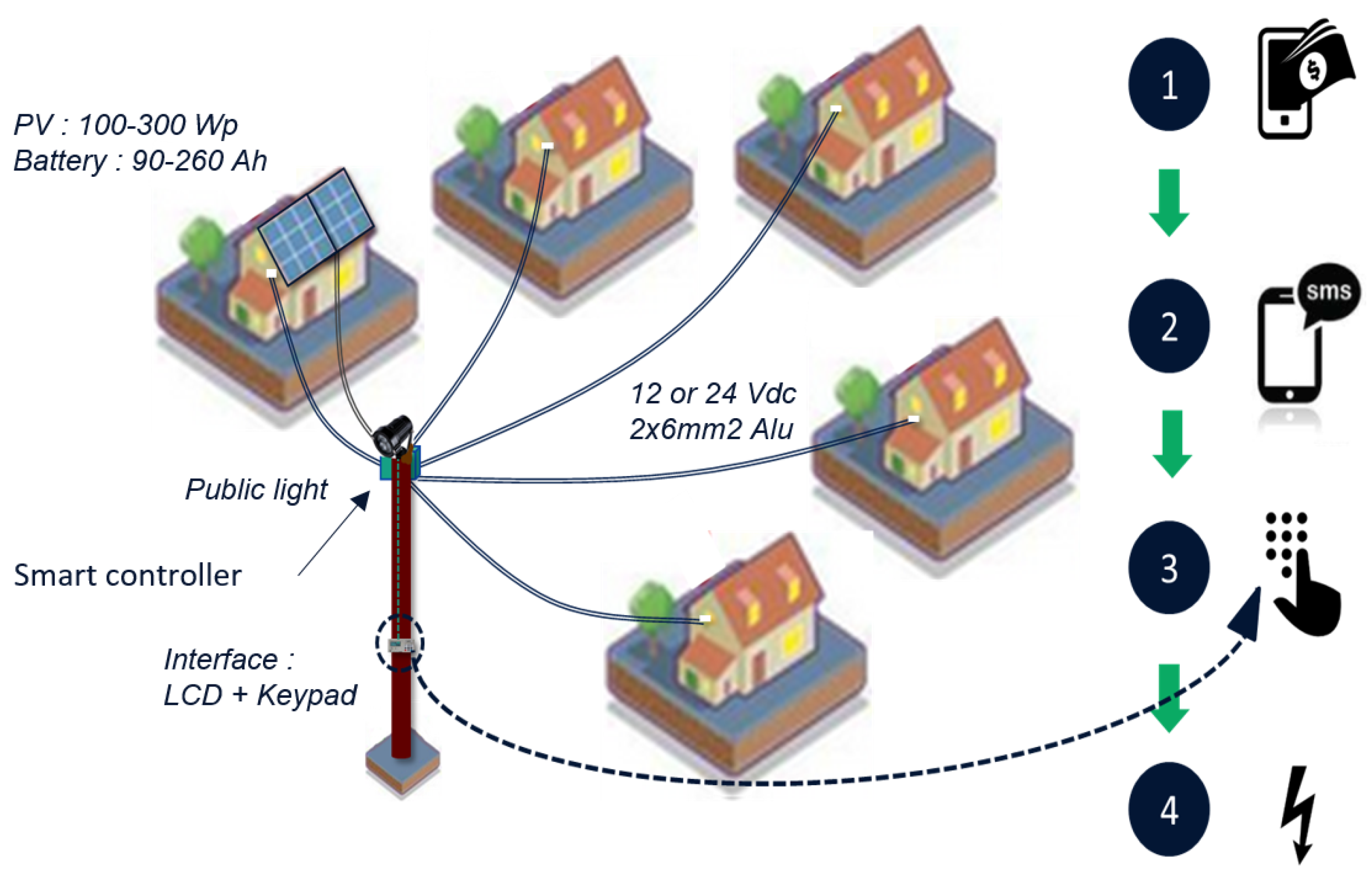
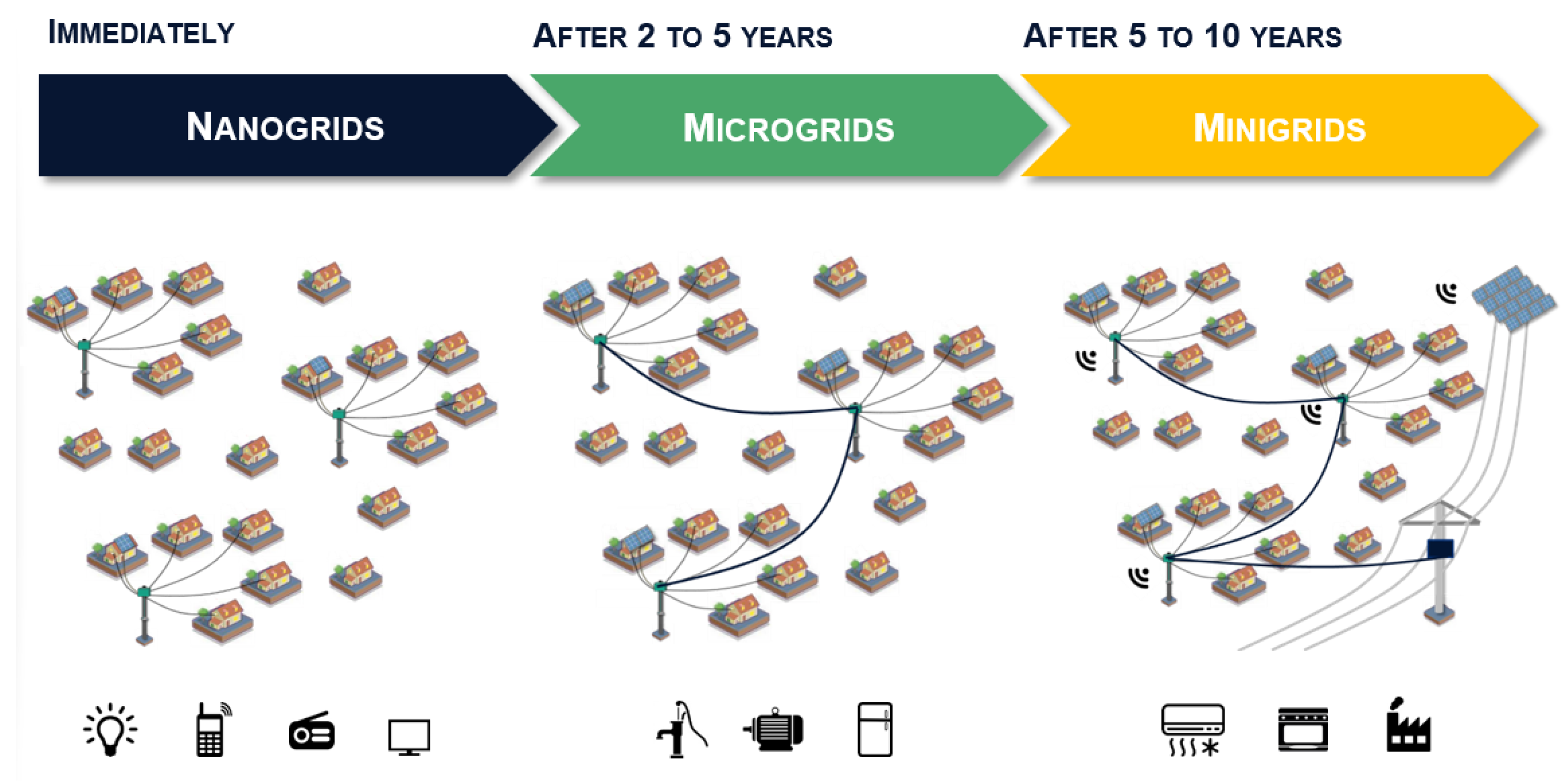
2.1. The Relevance of the Interconnection of Nanogrids

Initially, the NG solution is progressively disseminated based on the individual requests of the inhabitants. After this initial period, some villages can present an important spatial density of NGs. The NGs are originally oversized to ensure reliability and adapt to the likely growing demand from end users. Ambohimena, a typical Malagasy village, contains 27 NGs installed by Nanoé, relatively close to each other, as confirmed by Figure 3. The distances observed between two adjacent NGs are generally between 20 and 80 m.
An analysis of the consumption data of the 27 NGs of Ambohimena over 3 months (from July to September 2020) shows that the averaged depth of discharge (DoD) of the batteries of Ambohimena is of 13.9%, as shown by Figure 4. By mutualizing installed production and storage capacities, a village-wide DC microgrid would improve the reliability and the power level of the electric services brought to the community, helping households to progressively climb the energy ladder (from Tier 2 to Tier 3–4 [8]). Communal loads, such as water pumps or agro-processing machines, could be connected to the microgrid and be powered by all the NGs, thanks to the available excess of energy. In addition, the economic sustainability of the rural electrification project would be greatly enhanced as the hardware resources could be used more efficiently and additional electric services could be sold. For instance, the NG consumption data analysis enables to estimate the size of the global Ambohimena battery park needed for different levels of average DoD over the village, shown in Figure 5. With a microgrid and a target averaged DoD of 25%, the size of the battery park could be divided by 2, which represents a major financial saving. Interconnecting NGs to form a DC microgrid is therefore relevant for two mains reasons, i.e., an increased level of electrical services brought to the community and a better economic sustainability for the local electric operator.

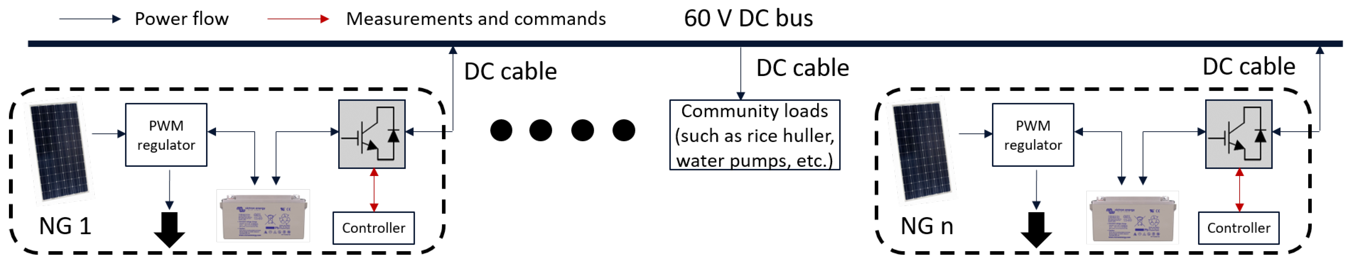
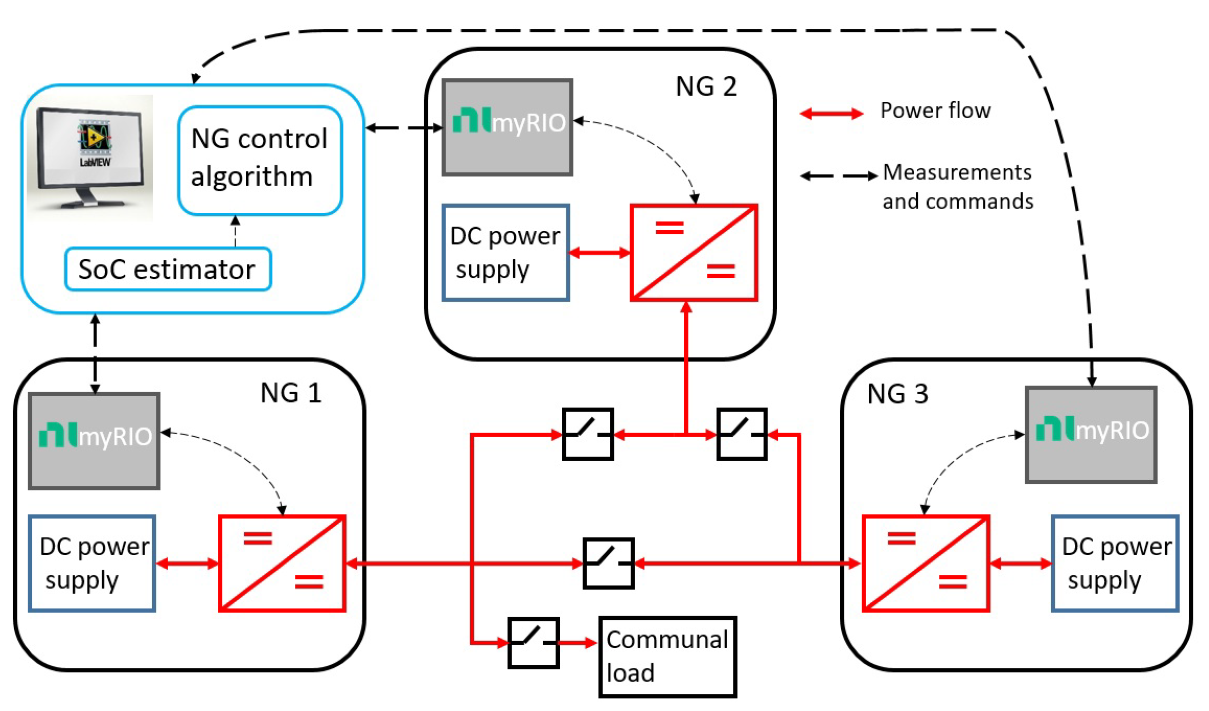
2.2. Topology of the Proposed DC Microgrid

The proposed microgrid is a DC microgrid with decentralized production and storage with a decentralized and communication-free algorithm. The decentralized production and storage feature is inherent to the Lateral Electrification model of Nanoé and is therefore not discutable in this research work. However, many papers justify the relevance of such DC microgrid architectures and its superiority over more centralized ones [3,12,28]. The control algorithm must be decentralized to avoid a single point of failure where any technical problems would impede the whole microgrid to operate. In addition, decentralized control enables plug and play feature for the NGs, i.e., they can be connected and disconnected from the microgrid at any time without impacting the operation of the rest of the microgrid. This is believed to be particularly useful, as the control architecture must not be changed, even if the microgrid grows within time, as expected. The rural zones of Sub-Saharan Africa offering no or unreliable telecommunication signals, a solution based on communication would decrease the reliability and increase the technical costs of the solution, hence the choice of a communication-free algorithm.
Figure 6 shows the configuration of the proposed microgrid, where NGs are connected to a 60 V DC bus through DC-DC bidirectional buck-boost converters. Communal loads, such as agro-processing machines or water pumps, can be connected to the DC bus, either directly or interfaced through a DC-DC buck converter, depending on the nature of the loads. NGs without batteries and possibly without solar panels could be connected to the 60 V DC bus through a bidirectional converter to increase the inclusivity of the proposed electrification model, by reaching households which cannot group in a 4 to 6 household cluster. The optimal voltage level of the DC bus still remains an open question, but a 60 V level is selected as the best compromise between safety of operation (by staying far below the extra-low voltage supply range of 120 V DC) and permissible power on the DC cables (by reducing the power losses and the associated voltage drops on the 2 × 16 mm 2 DC cables).

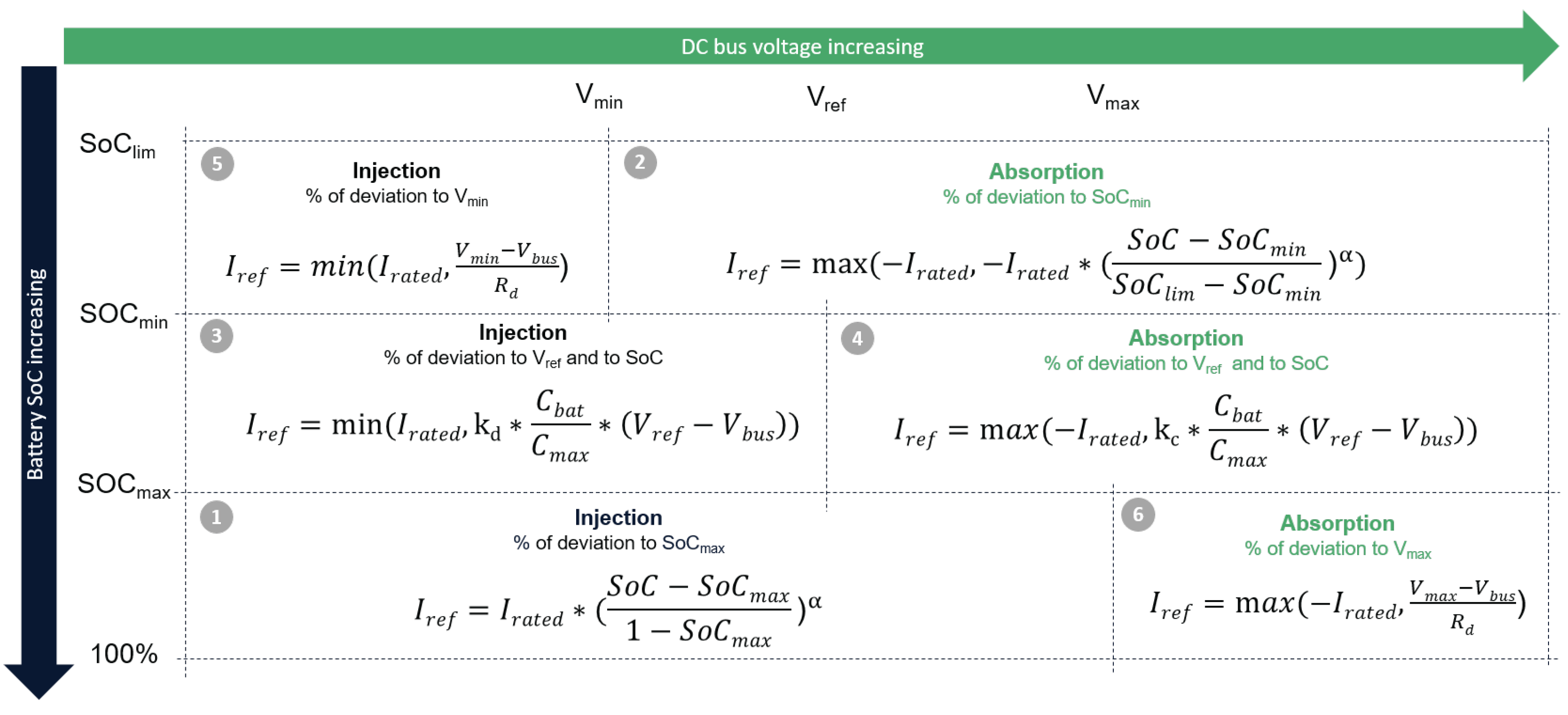
2.3. A Decentralized Communication-Free Control Algorithm

The control algorithm must ensure relevant power flows on the DC microgrid, while guaranteeing stability and maintaining the DC bus voltage within a pre-defined voltage range. The control algorithm is not designed to achieve perfect battery balancing but to do battery rescuing or battery supporting. As the control is decentralized and communication-free, it must only rely on local variables, straightforward to measure. The level of available energy is indicated by the SoC of the battery of the NG, while the global level of available energy on the microgrid is indicated by the only common variable for all the NGs, i.e., the DC bus voltage (modulo the voltage drops on the DC lines). The higher the DC bus voltage, the higher the global level of available energy on the microgrid and vice versa. A limit at ± 10 % is set on the DC bus voltage to control and maintain the DC bus voltage within a pre-defined range. In addition, this relationship between the DC bus voltage level and the global level of energy on the microgrid is useful for further expansion of the electric infrastructure (e.g., microgrid interconnection or connection to an AC grid). Furthermore, three levels of battery SoC are defined: weak level from 0 to 60% SoC, medium level for 60 to 80% SoC and strong level for above 80% SoC. The control algorithm must ensure that any NG with a higher SoC range supports the other NGs with a lower SoC range, with respect to their respective energy reserve.
The proposed control algorithm, based on [11] with additional modifications on the mode equations, is shown in Figure 7. Depending on its SoC level and the measured DC bus voltage, a NG must control energy sharing, i.e., its current injection or absorption on the DC bus. Different current reference formulas ( I r e f ) are then defined, depending on which mode the NG is. To avoid any edge or pumping effects, the 3D map of the control algorithm (i.e., the current reference vs. the DC bus voltage and battery SoC) is made continuous with respect to the DC bus voltage and the SoC to prevent successive changes of mode with a high current reference amplitude. Hyperbolic tangents on the SoC and the DC bus voltage are therefore introduced at every mode to smooth the current reference variation while at the boundary of two adjacent modes. A limit at I r a t e d is set on the maximum absorbed or injected current to avoid deterioration of the battery lifetime. Table 1 summarises the different parameters of the proposed control algorithm.
An optional selfish behavior can be added to the control algorithm to prevent the first NGs that reach a strong SoC range to directly support NGs in the medium range without finishing a complete charging. To this end, the value of S o C m a x can be first set to 95% then switch to 80% when the SoC exceeds 95% (i.e., self-recharging can be considered almost complete). However, those selfish NGs would still rescue NGs which are in the weak SoC range.

3. Design through Pseudo-Dynamic Simulations

3.1. High-Level Simulations

Software simulations are necessary to validate and tune the control algorithm shown in Figure 7 and overall confirm the proper operation of the proposed DC microgrid. High-level simulations on Matlab-Simulink are first studied to observe long-term power flows on the DC microgrid with a time frame of a few days. The impact of the control algorithm on the power flows on the DC microgrid and the SoC of all NGs must be thoroughly analyzed. The microgrid simulated interconnects five NGs, as shown in Figure 8, based on five NGs of Ambohimena (cf. Figure 3). To enable long-term simulations within a few minutes, averaged models are used for the DC-DC converters [35] and the batteries to model the NGs and the interconnection modules connecting the NGs to the DC bus. Furthermore, the simulation model includes the resistance of the DC cables and can also easily be extended with additional NGs and even with NGs without batteries or communal loads. Real data collected on the field in Ambohimena are used for the NG consumption. The same irradiation profile is used for all NGs [36].

3.2. Simulation Results

Figure 9, Figure 10 and Figure 11 show the evolution of the DC bus voltage, the currents exchanged between the NGs and the SoC of the 5 NGs from 21 September 2020 at 3:40 p.m. to 25 September at 12:00 p.m., with the consumption data of NGs 29 and 168 artificially doubled to simulate a high increase in the NG demand. The SoCs are initialized at low levels for 3:40 p.m. and all the NGs are in the medium zone. During the first night, all the NGs reach a SoC below 60%, even if NGs 1, 54 and 211 try to support NGs 29 and 168. Hence, the DC bus voltage stabilizes at 54 V, indicating a weak microgrid. Then, during the first day, once NGs 1, 54 and 211 reach a SoC above 60%, they start to support NG 29 and NG 168, which helps them to reach back the medium SoC zone. Note that the selfish behavior for the NGs is implemented here, with a S o C m a x initially at 95% then at 80% to favor self-recharging. Therefore, the NGs wait until their SoC reaches 95% before supporting medium zone NGs. Over the next few days, as shown in Figure 10, NGs 1, 54 and 211 frequently support NGs 29 and 168 and bring them back within the strong SoC zone in 2 days, as confirmed in Figure 11. Figure 9 illustrates well that the DC bus voltage translates the averaged level of available energy on the microgrid. In addition, Figure 12 shows the evolution of the SoC of the 5 NGs without a microgrid. It can be seen that the SoC of NGs 29 and 168 reach dramatic levels, which would deteriorate the lifetime of the batteries and provokes blackout on the NGs, whereas the 3 other NGs have plenty of energy to share. Moreover, without a microgrid, the solar panels of NGs 1, 54 and 211 would often curtail their production as the local battery on the NGs would be full. These results show that interconnecting NGs enables a better usage of hardware resources and increases reliability. Overall, these simulations allowed to validate the control algorithm and to precisely tune its different parameters, such as the droop coefficient R d or the coefficients in the hyperbolic tangents for example.
To include NGs without battery and solar panel or communal loads, the control logic should be adapted. In both cases, the interconnection module linking the DC bus to the communal load or the NG without battery must regulate a fixed voltage on the NG/communal load side, for instance, 12 or 24 V for a NG without battery and 48 V for a communal load operating on a DC motor rated at 48 V. Different types of communal loads can be considered, such as water pumps, agro-processing machines or AC inverters to power AC loads. Powering communal loads only when the DC bus voltage is high is also a possibility, as this traduces a high level of available energy of the microgrid. This is particularly relevant for water pumps which must fill a tank: their time of operation can easily be shifted without impacting them too much.
Figure 13, Figure 14 and Figure 15 show the operation of the DC microgrid with a 500 W communal load operating between 12 p.m. and 3 p.m. every day and located between NGs 54 and 168 as indicated in Figure 8. The interconnection module linking the communal load with the DC bus voltage regulates the voltage at the communal load side at 48 V. When the communal load starts to extract power, the communal load bus voltage starts to decrease and to counteract this, the interconnection module absorbs current from the microgrid. Each NG then contributes to power the communal load with respect to their own SoC and their distance to the communal load. Note that the consumption of NGs 29 and 168 is not artificially doubled anymore as the microgrid is already experiencing a higher demand due to the communal load. A communal load of 1500 Wh per day is quite important for a microgrid composed of only 5 NGs. However, the microgrid succeeds in powering the load, while the NGs do not reach the low SoC zone. In comparison, without the communal load, the SoCs obtained are shown in Figure 16 and are much higher. Ultimately, the choice of installing a communal load on the DC microgrid will be a compromise between the DoD of the batteries and the additional electrical services brought to the community.

3.3. Low-Level Simulations for Stability Analysis

After validation of the proposed microgrid design and its control algorithm through high-level long-term simulations, low-level simulations with a detailed switching model of the converters are needed to assess the stability of the microgrid. The microgrid simulated is similar to the one in Figure 8 but the switching parts of the converters are modeled with a small time-step.
A preliminary study of the stability of the proposed microgrid is carried out. The stability of the microgrid is observed after sudden large changes of the DC bus voltage. Those sudden changes greatly modify the current references given by the proposed control algorithm, and a new operating point is reached for the microgrid. The transition between operating points must not generate voltage oscillations on the DC bus to guarantee overall stability. Different DC bus voltage disturbances (through the sudden connection or disconnection of a communal load) were tested as shown in Figure 17. The evolution of the DC bus voltage, the battery currents and the SoCs of the NGs are illustrated with sudden changes of operating points, with the connection of a 10 Ω power resistor on the DC bus at t = 0.5 s (i.e., 360 W on a 60 V DC bus), its disconnection at t = 1 s and the connection of a 6 Ω power resistor at t = 1.5 s (i.e., 600 W on a 60 V DC bus). The results show that the overall stability is guaranteed despite sudden and important changes of the operating points.
However, this is only a preliminary study whose results are limited to the cases tested. A more comprehensive study is needed to assess the stability limits of this DC microgrid and to understand the impact of each parameter on the stability (number and distance between NGs connected, droop parameters, power rating, etc.).

4. Experimental Validation on a Test Bench

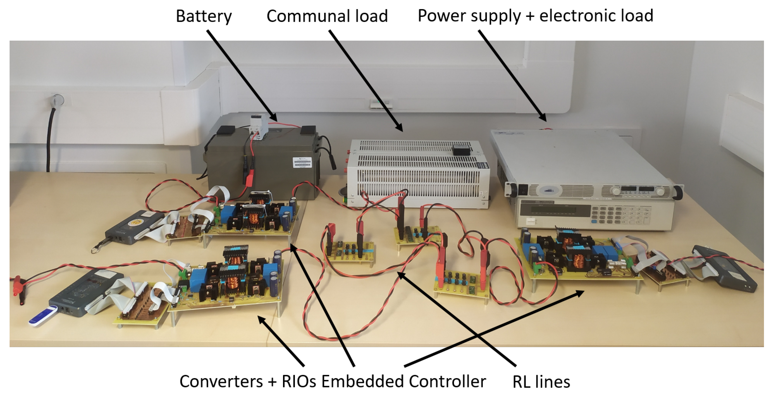
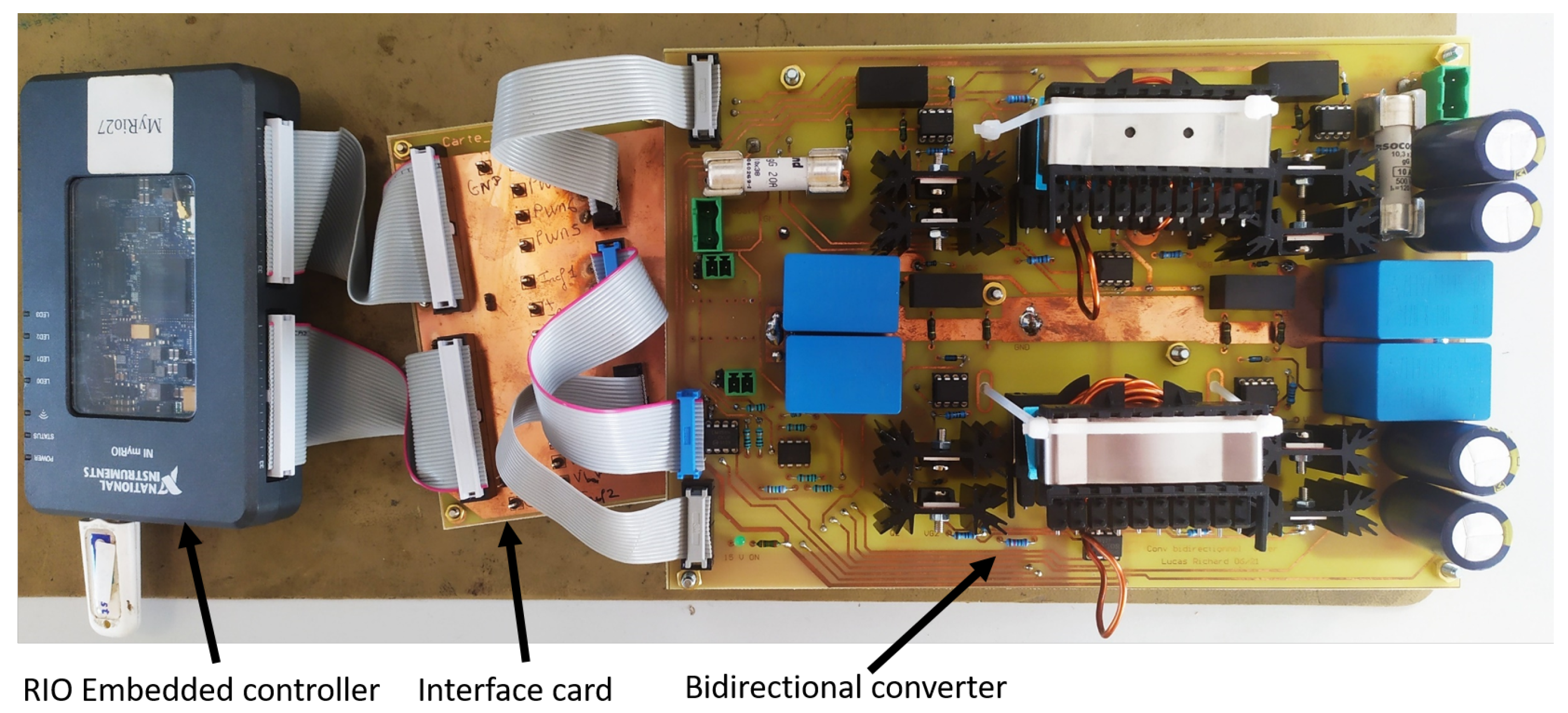
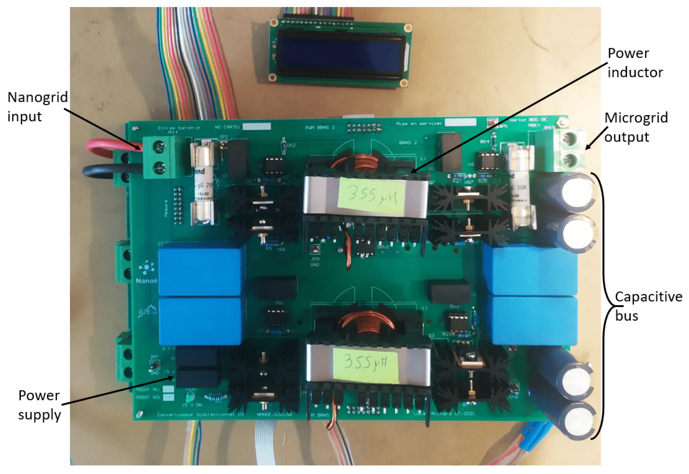
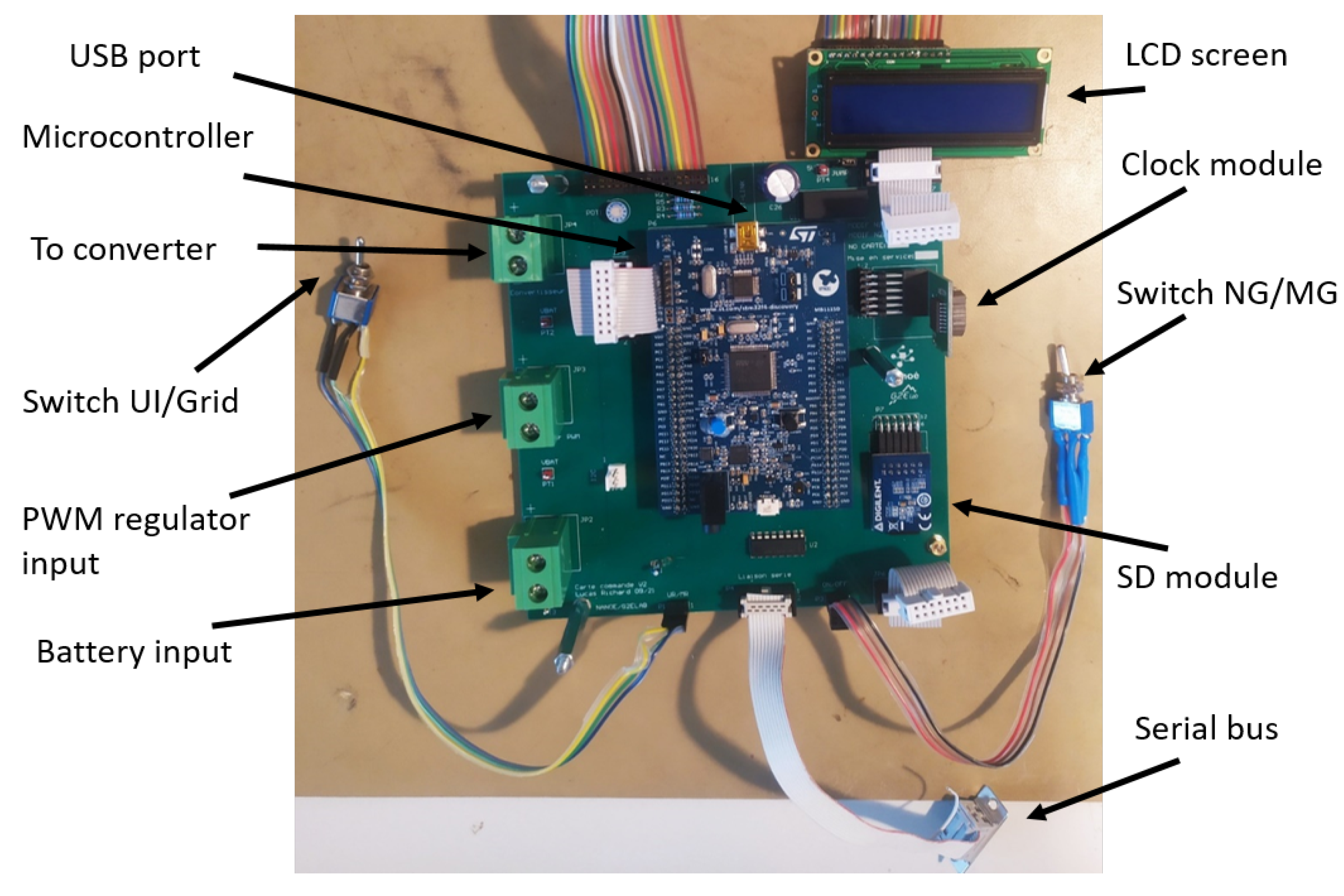
4.1. Development of a Test Bench

In the microgrid field, lab testing is unavoidable to provide a complete experimental validation of the microgrid designed with the help of simulations. Furthermore, field deployment of DC microgrids in rural places is often expensive, logistically difficult and time consuming, making it important to conduct extensive laboratory testing to avoid any unexpected results on the field.
The objective of the test bench is to create a lab environment, which replicates as closely as possible the real field conditions, with additional safety, monitoring, ease of installation and testing capacities. The test bench consists of 3 DC-DC bidirectional buck–boost converters interconnected through RL lines which emulate the impedance of the electric lines of the field (with four distances available: 20, 40, 60 and 80 m) [37]. The cabling set-up can be reconfigured easily as indicated on the schematic of the test bench in Figure 18. The test bench represents a microgrid with 3 NGs interconnected. A power supply in parallel to an electronic load or a battery is placed at the input of each converter. A power resistor whose value can be adjusted can be connected to the DC bus to emulate a communal load. The developed test bench can be seen in Figure 19.
The DC-DC converter is a 18 Amp two-arm interleaved bidirectional buck–boost converter [37]. Without galvanic isolation needed, a buck–boost converter is considered the best compromise between ease and time of design, cost and additional functionalities. Indeed, protection and start-up services are necessary for the proper operation of a DC microgrid on the field. Hence, it is economically relevant to include them in the converter instead of adding costly additional components, such as a DC circuit breaker, for instance. Mosfets Q1 and Q5, as shown in Figure 20, are necessary to completely disconnect the NG (on the left) from the microgrid (on the right) by opening them. In addition, Q2 and Q6 are useful to offer a freewheeling path to the current in inductors L 1 and L 2 in the case of external default and then limit the constraints on the interface semiconductors (Q1, Q3, Q5, and Q7). Overall, the arms Q1/Q2 and Q5/Q6 are of particular interest to operate the converter in buck mode. As the DC bus contains high value capacitance to stabilize the DC bus voltage and enhance global inertia, the initial inrush current when starting the first converter can be high to charge all the capacitors to the operating voltage. A smooth start-up procedure is considered by starting the converter in buck mode (with arms Q1/Q2 and Q5/Q6 switching and Q3 and Q7 closed) to slowly charge the DC bus capacitance then switching to boost mode (Q1 and Q5 closed and arms Q3/Q4 and Q7/Q8 switching). This greatly limits the initial inrush current as shown in Figure 21, where the left and right figures show the initial inrush current and the DC bus voltage, respectively, without and with a start-up procedure. Furthermore, if the DC bus voltage suddenly drops to a lower value than the NG voltage (following a fault for instance), a boost structure would fail due to the presence of the body diode of Q3 and Q7. Under such events, the converter could switch to buck operation to overcome the fault or completely disconnect the NG from the microgrid by opening Q1 and Q5.
The lab prototype of the converter presented in Figure 22 is controlled by a RIO Embedded Controller from National Instruments programmed in LabVIEW [38]. On the test bench, each converter is current controlled by an individual RIO controller, which also enables data recording, implementation of the decentralized and communication-free control and scenario studies through a SoC estimator of the emulated batteries. In addition, a graphic user interface (GUI) offers ease of monitoring on the test bench. The RIO controller determines the current reference with the decentralized and communication-free control algorithm, presented in Section 2.3, that the converter must follow. A PI regulator, whose gains K p and K i are indicated in Table 2, is then used to regulate the current of the converter to its reference. Finally, Table 2 summarizes the parameters of the developed converter and test bench.

4.2. Experimental Power Flows on the Microgrid Test Bench

The test bench enables to monitor the power flows between the three converters. Figure 23 shows the evolution of the DC bus voltage, the SoC of the emulated batteries and the currents exchanged between the three converters. Note that a positive current means that the converter injects on the microgrid and vice versa. The SoCs evolve according to user-defined patterns to test different operating points. The three emulated batteries and converters are named, respectively, NG 1, NG 2 and NG 3. The results of Figure 23 illustrate the following steps:
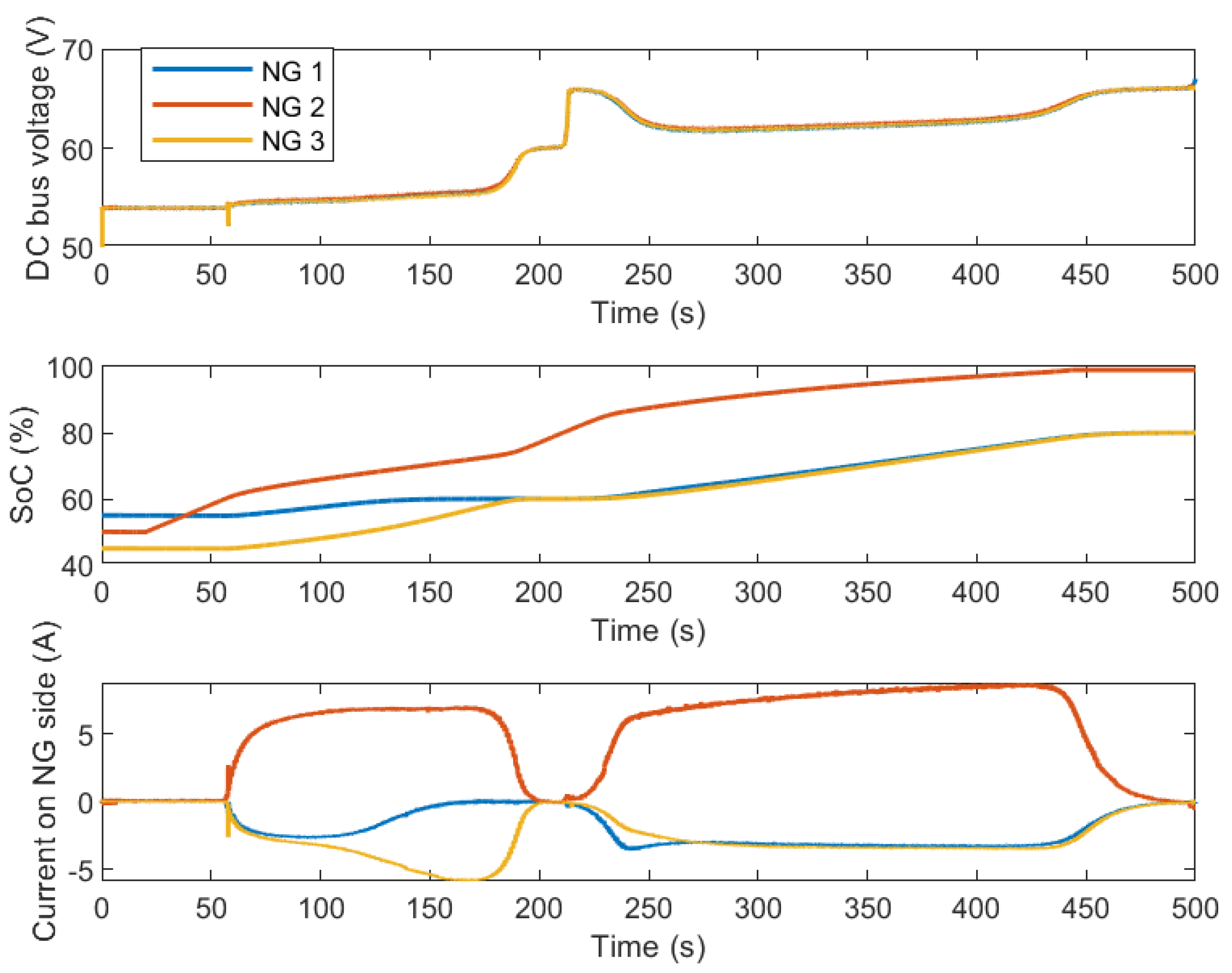
  • The 3 NGs start with a SoC below 60%.
  • At t = 60 s, NG 2 reaches 60% of SoC whereas NG 1 and NG 3 are still in the weak zone. Therefore, NG 2 starts to inject current (with respect to its SoC) on the microgrid to rescue NG 1 and NG 3.
  • Once NG 1 and NG 3 reach 60% of SoC, the DC bus voltage stabilizes at 60 V, showing that the global level of energy of the microgrid is medium.
  • At t = 220 s, NG 2 reaches 80% of SoC, and therefore it supports NG 1 and NG 3 until the DC bus voltages stabilizes at 66 V, traducing a high level of SoC for all the NGs in the microgrid.
It has to be noted here that the selfish feature of the control algorithm has not been implemented. It is interesting to note that when NG 2 starts to inject current at t = 220 s, the DC bus voltage shortly stabilizes at 66 V because NG 1 and NG 3 did not respond quickly enough to the increase in voltage. This is due to an inherent delay of the electronic loads used in the test bench when the currents are low. They start to absorb current a few seconds after they should have, which makes the DC bus voltage increase momentarily. However, it is safely maintained below 66 V by the control algorithm, which reduces NG 2 injection until the electronic loads respond.
Figure 24 shows the operation of the microgrid when a communal load (i.e., in this case, a power resistor) is connected to the DC bus. The following steps are illustrated:
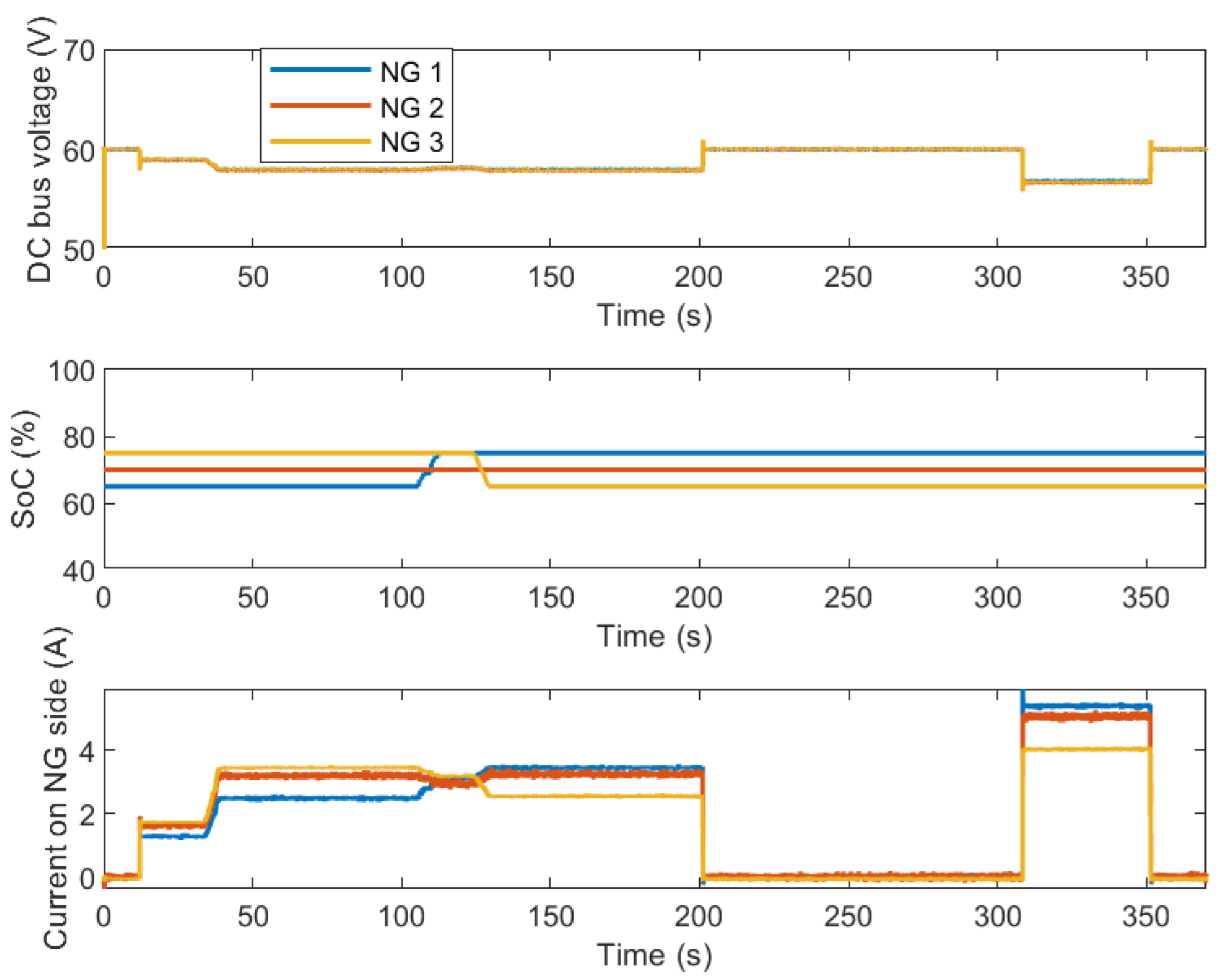
  • The SoCs of the emulated batteries are initialized between 60% and 80%, in the medium range.
  • A t = 10 s, a 60 W power resistor is connected.
  • Then its power consumption is increased from t = 30 s to t = 40 s to 120 W. Each NG injects a current on the DC bus with respect to their SoC, i.e., the higher the SoC, the higher the current injected.
  • At t = 110 s, the SoC of the emulated batteries is manually changed to emphasize this current sharing feature.
  • The communal load is then disconnected at t = 200 s and reconnected with a greater power consumption (i.e., 180 W) at t = 310 s.
The relationship between the DC bus voltage and the global available energy of the microgrid is highlighted with the DC bus voltage being lower when the power resistor consumption is greater, as there is less available energy left on the microgrid due to the high consumption of the power resistor.
This test bench validates the proper operation of the proposed microgrid with a high number of subsequent successful tests (meshed or radial topology, 12 or 24 V NGs, protection and start-up features) [37]. Moreover, the control algorithm is tuned during the preliminary phases of testing, in particular, the slopes of the hyperbolic tangents. Overall, the control algorithm needs to be less aggressive to prevent from any oscillations in the current reference. It is the belief of the authors that the control must purposefully be slowed down to avoid any instabilities or oscillations on the DC bus. The results show that the control algorithm enables relevant power flows on the DC microgrid while maintaining the DC bus voltage within a pre-defined limit. In addition, thanks to the RIO embedded controller and LabVIEW, the fast prototyping of a DC-DC converter and a test bench is doable and permits to quickly validate the design of the microgrid and its control algorithm without the long engineering time associated with the use of micro-controllers [37].

5. Field Deployment in Madagascar

5.1. The Interconnection Module

After the design and validation of the proposed DC microgrid through software simulations and experimental testing, field deployment is the next step of this microgrid project. However, in the research level, field deployment remains rare, as it is logistically difficult, time consuming and expensive. In addition, going from a lab test-bench prototype to a field-ready prototype requires a high amount of work. It is still undoubtedly necessary to completely validate a microgrid design as field installation and field operation might reveal problems hidden in the software simulations or the test bench testing. In addition, field testing feedbacks on the installation, operation and maintenance of the DC microgrid is of great help for further improvements.
The interconnection module developed in-house in the G2ELab is composed of a power card (Figure 25), i.e., a 18 Amp two-arm bidirectional buck–boost converter and a command card (Figure 26) controlling the power card and managing the peripherals of the interconnection module (LCD screen, switches, SD card, USB and serial ports, etc.) thanks to a STM32 micro-controller. A SoC estimator is included in the command card. The power card is mounted over the command card and both are included within a plastic box on which the peripherals are mounted.
This interconnection module has three modes of operation:
  • MG mode where the interconnection module exchanges energy with the microgrid and manages protections, data recording and estimation of the SoC (through Coulomb counting method);
  • NG mode, in case of maintenance on the microgrid, where the interconnection module only records data and estimates the SoC of the battery;
  • UI (user interface) mode for bidirectional communication between a computer and the command card through the serial bus for maintenance and data collection operations on the interconnection module.

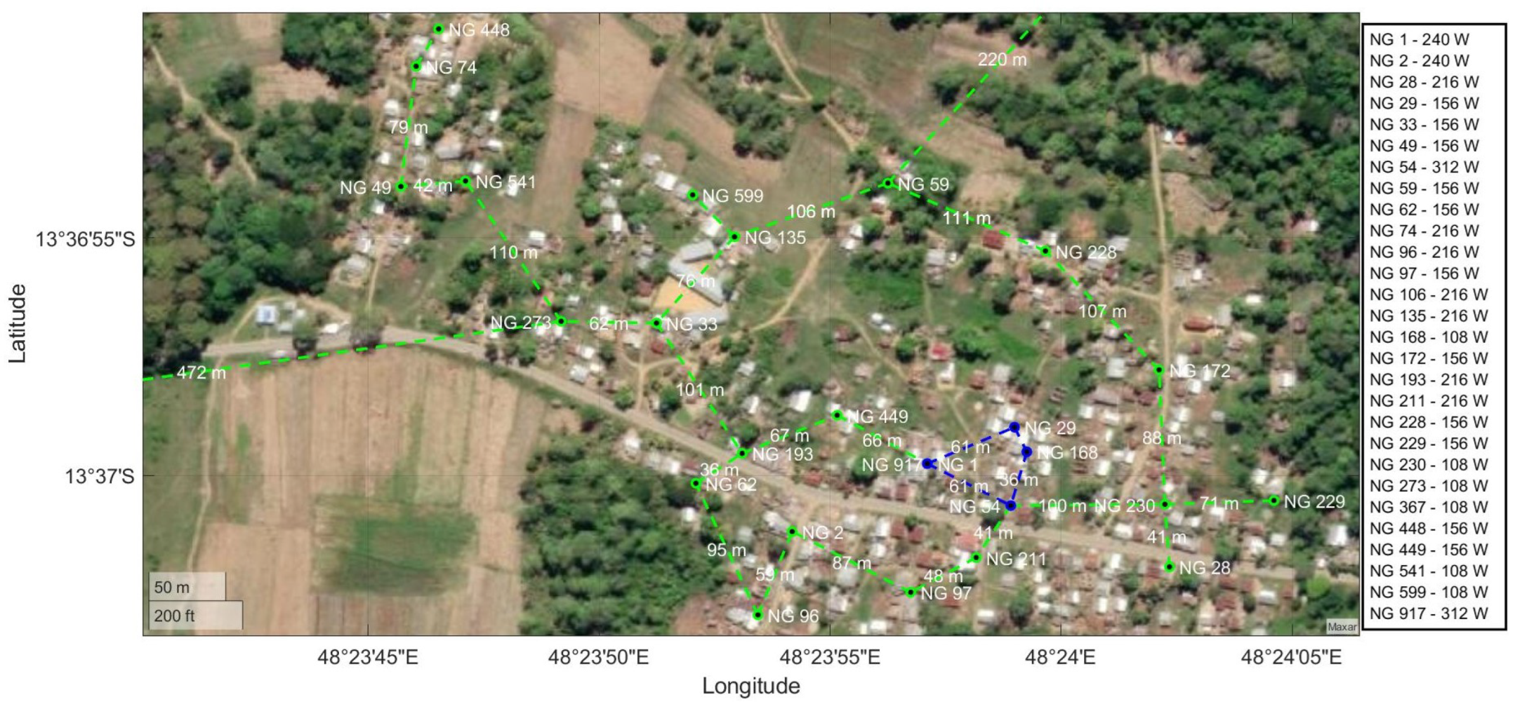
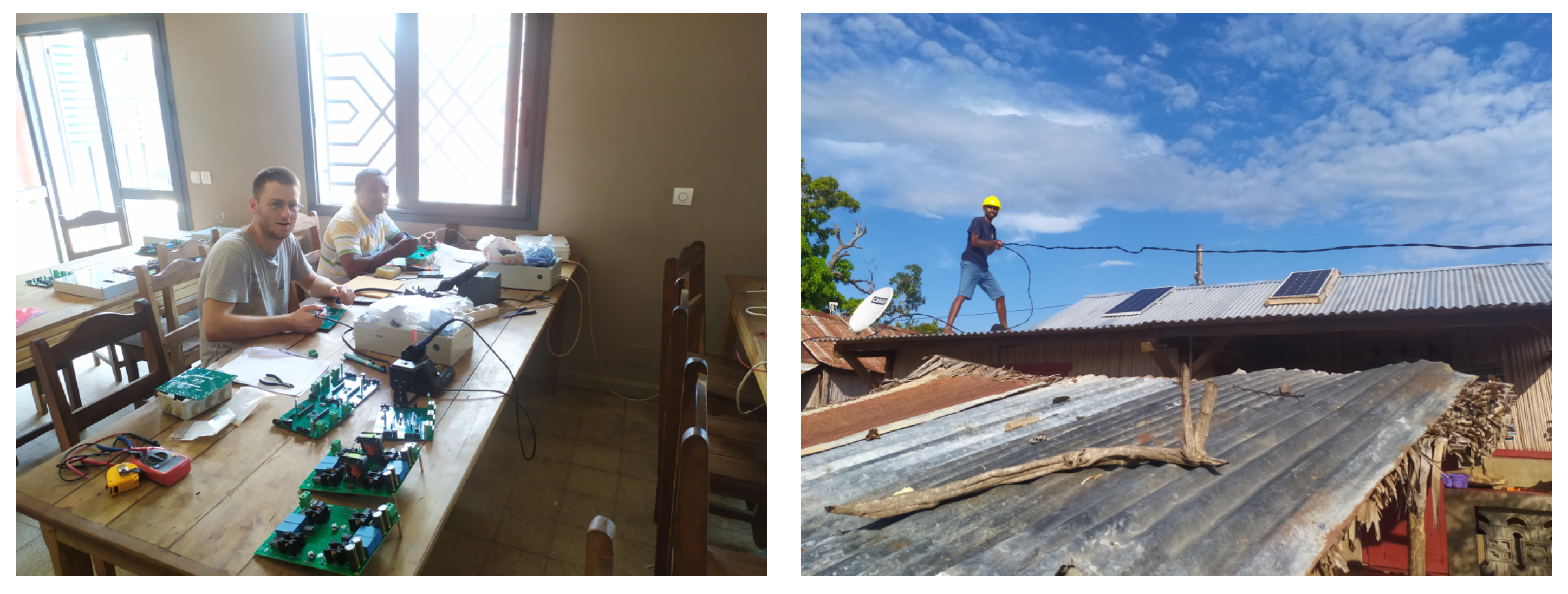
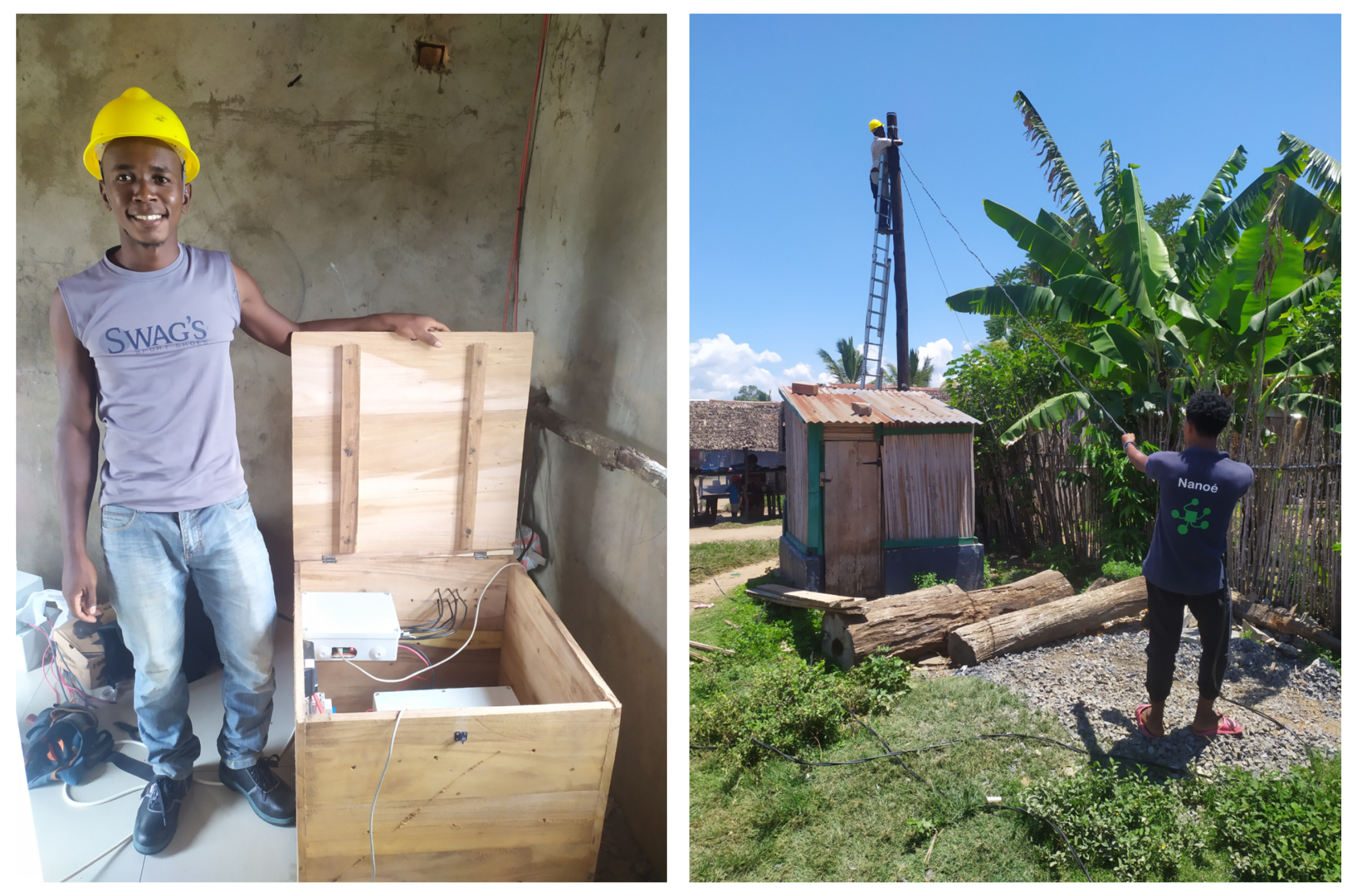
5.2. Installation of the Microgrid on the Field
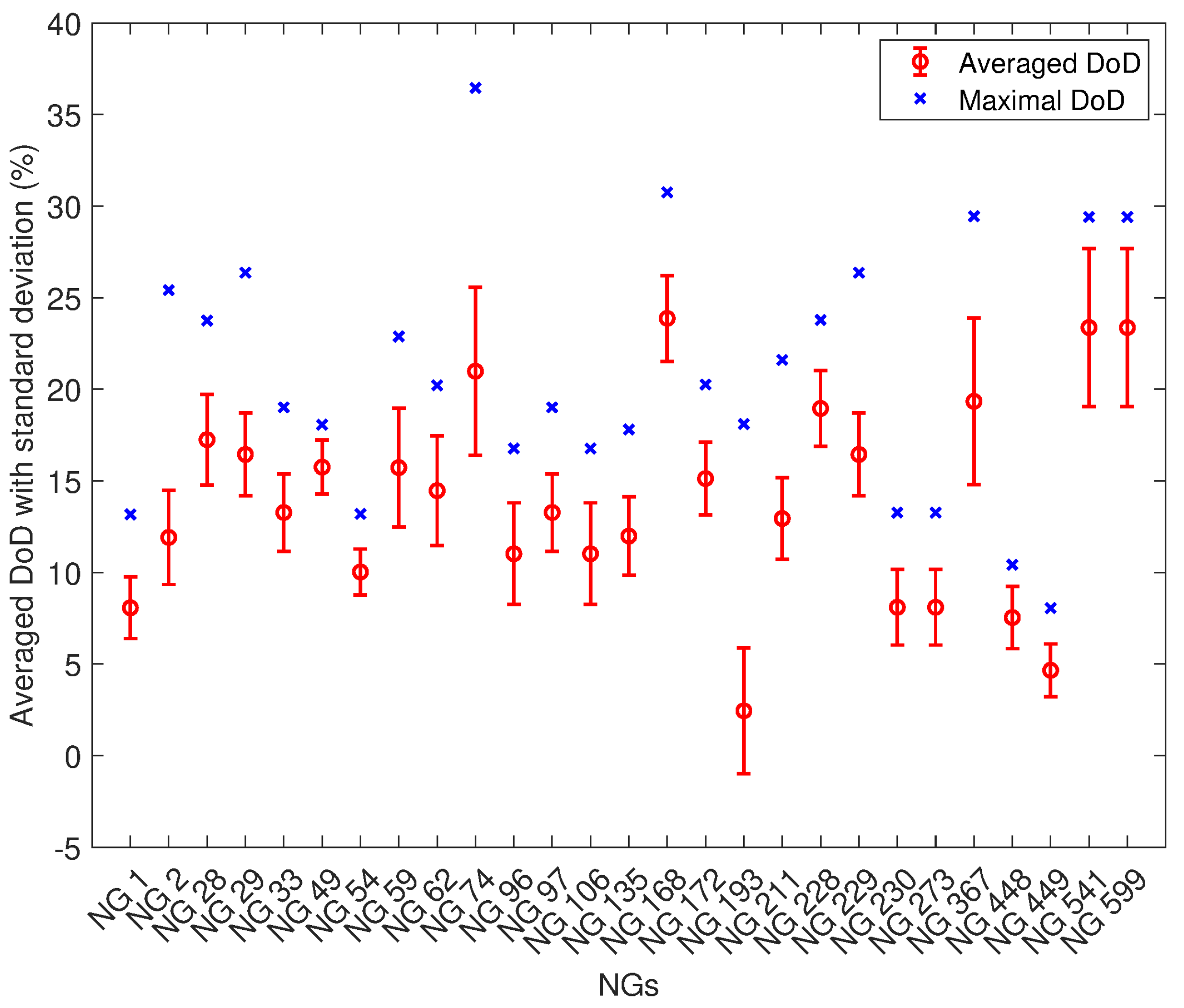
Between November and December 2021, a 5-week mission in Madagascar was conducted to install a first microgrid on the field. Five NGs were selected in Ambohimena for the interconnection after discussion with the Ambohimena mayor and Nanoé’s staff, including NG 917, recently installed and temporarily undersized to test the supporting capability of the microgrid. The interconnection modules were locally mounted and tested in Madagascar by Nanoé’s staff, as shown in Figure 27.
Three days of labor were needed to install the interconnection modules, the wooden poles and the electric cables, as shown in Figure 27 and Figure 28. The schematic of the installation is presented in Figure 29. For the installation, 16 mm2 cables were used.

5.3. Field Results

The microgrid of Ambohimena was successfully launched for the first time on 2 December 2021. Figure 30, Figure 31 and Figure 32 show the evolution of the currents exchanged between the NGs, the SoC of each NG and the DC bus voltage from 16 to 23 December. The following steps are illustrated:
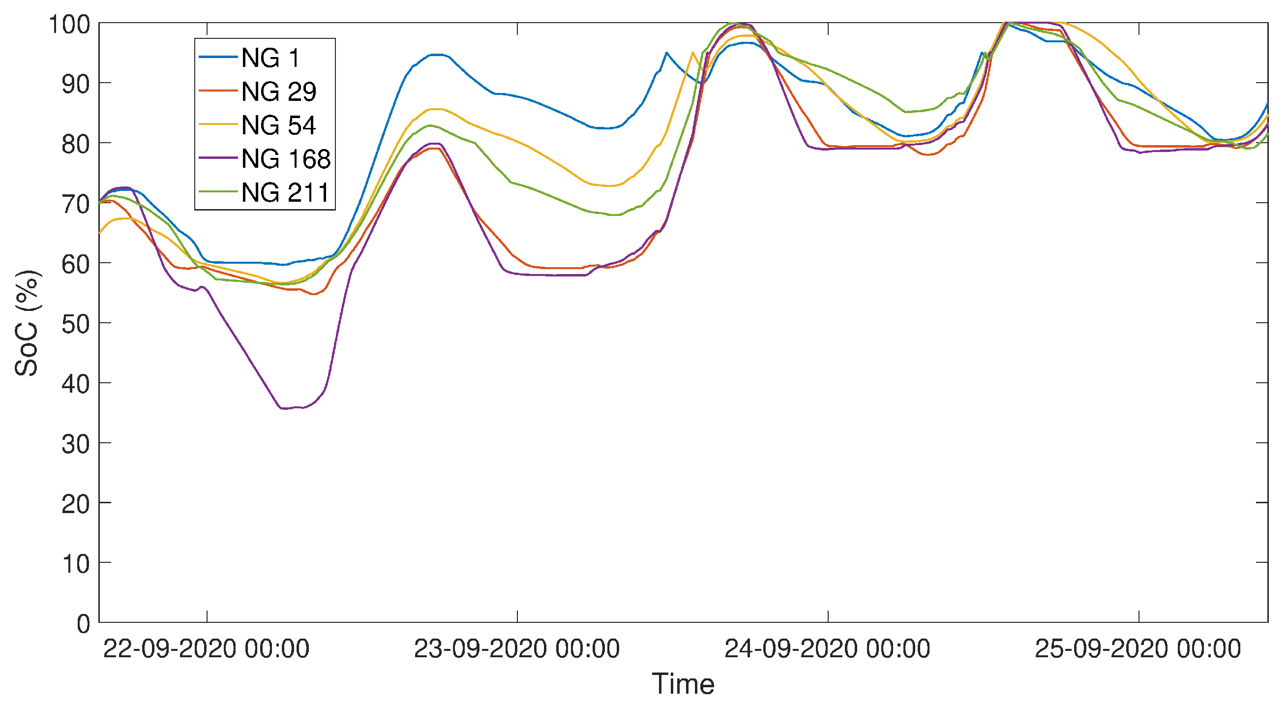
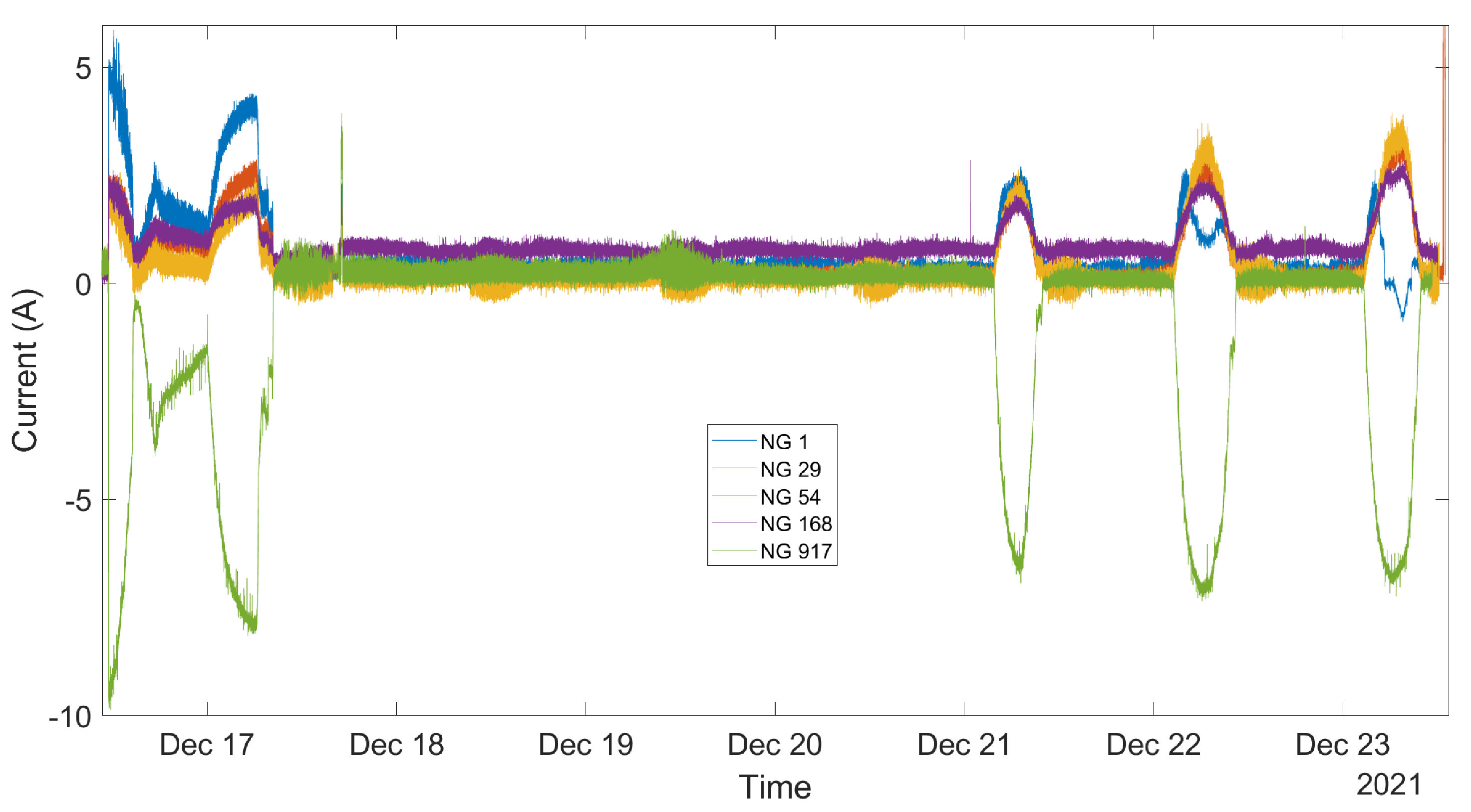
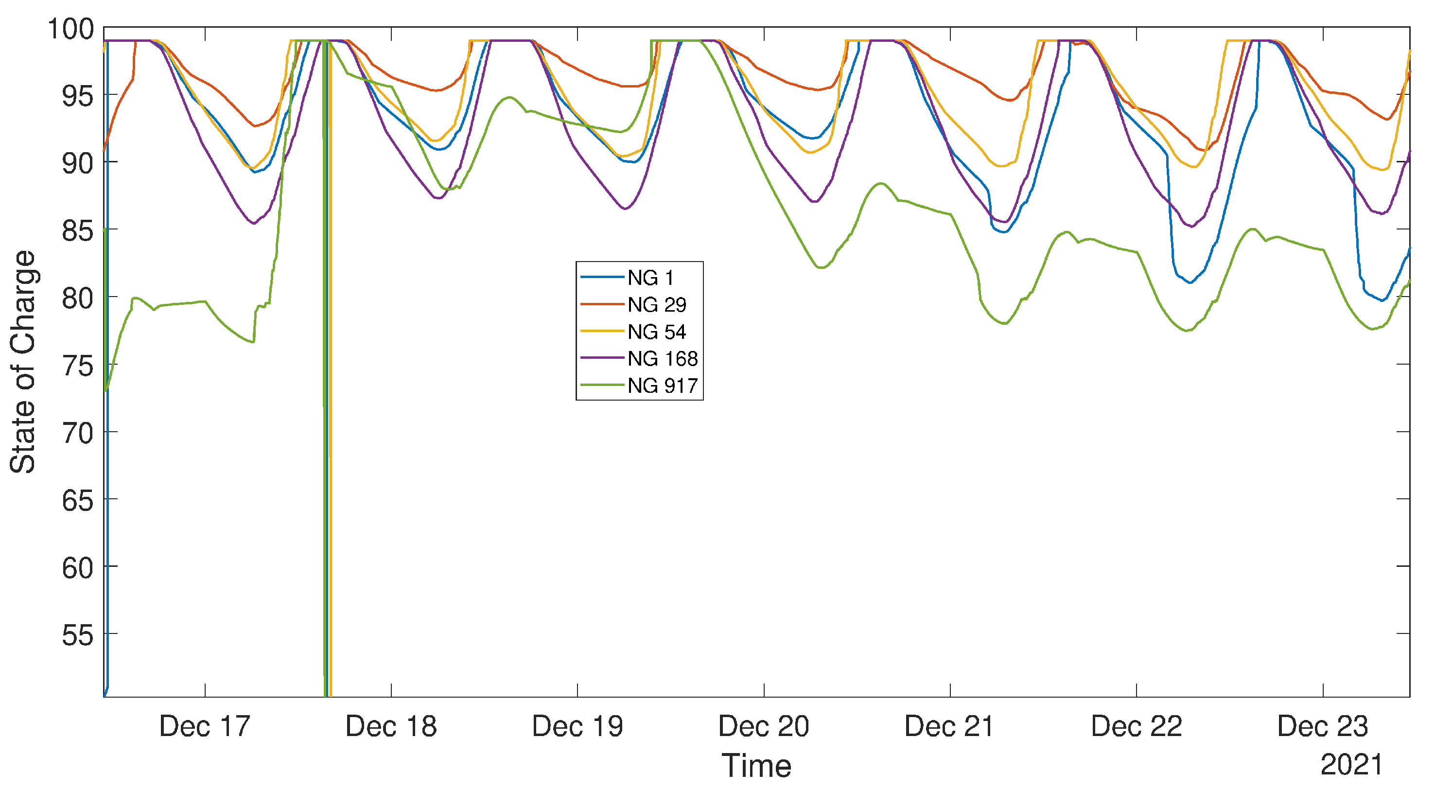
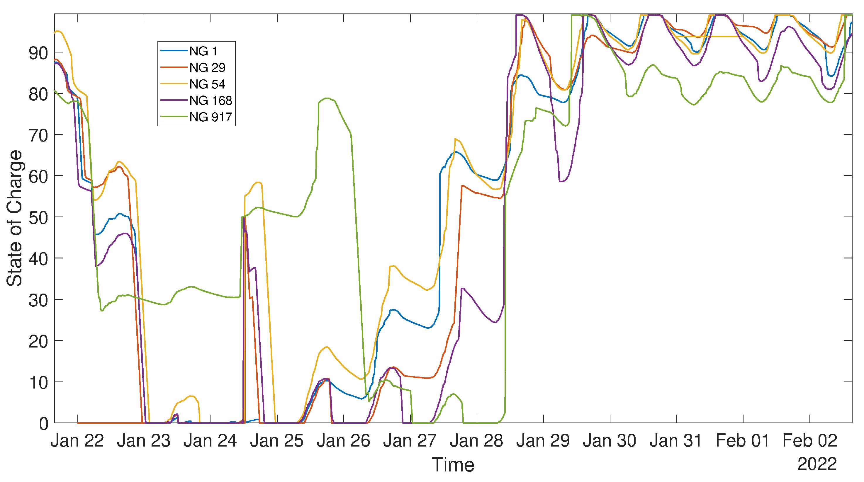
  • The microgrid is launched with NG 917 slightly undercharged. Therefore, the 4 other NGs supported NG 917 for the first 24 h until NG 917 reaches a SoC of 80%.
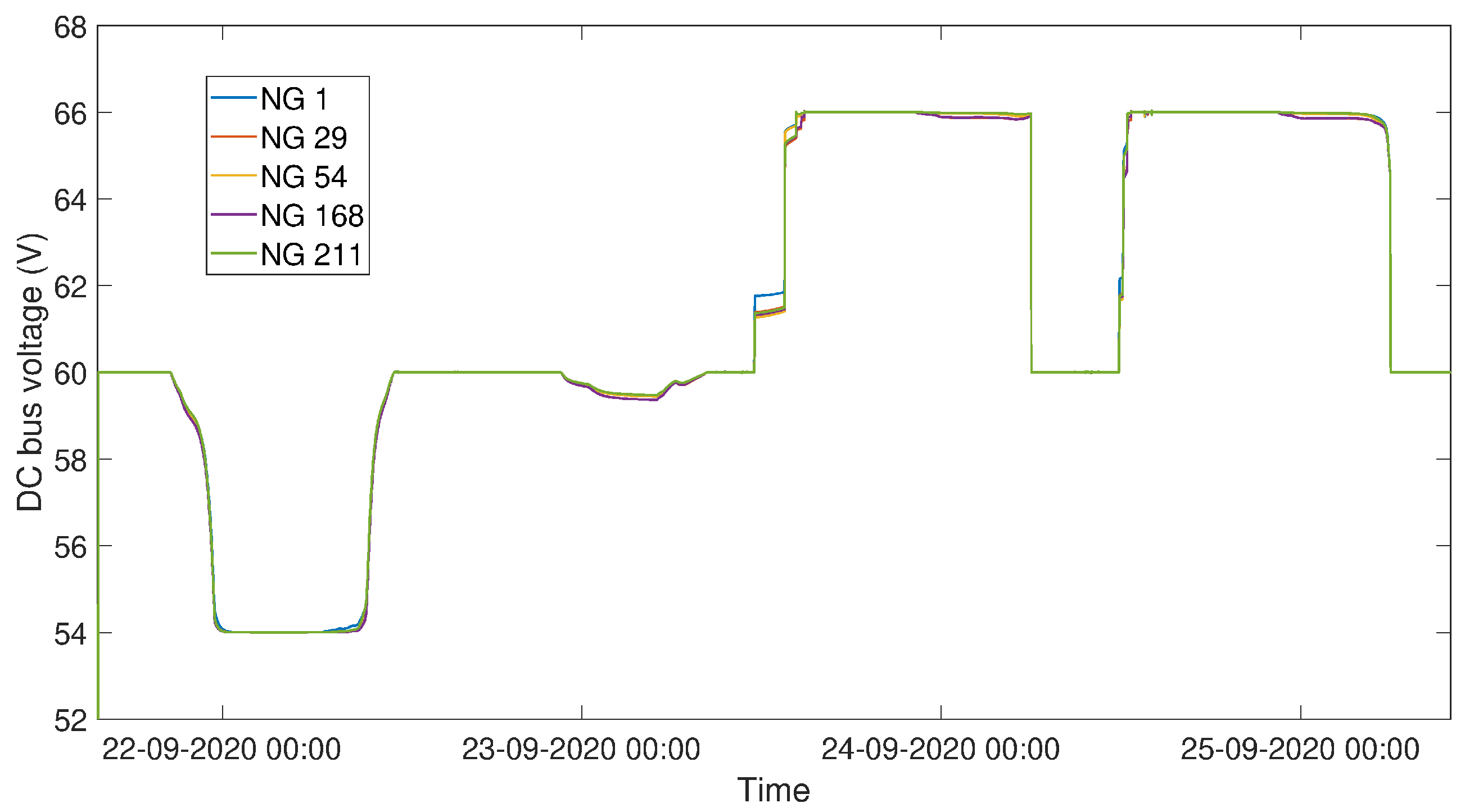
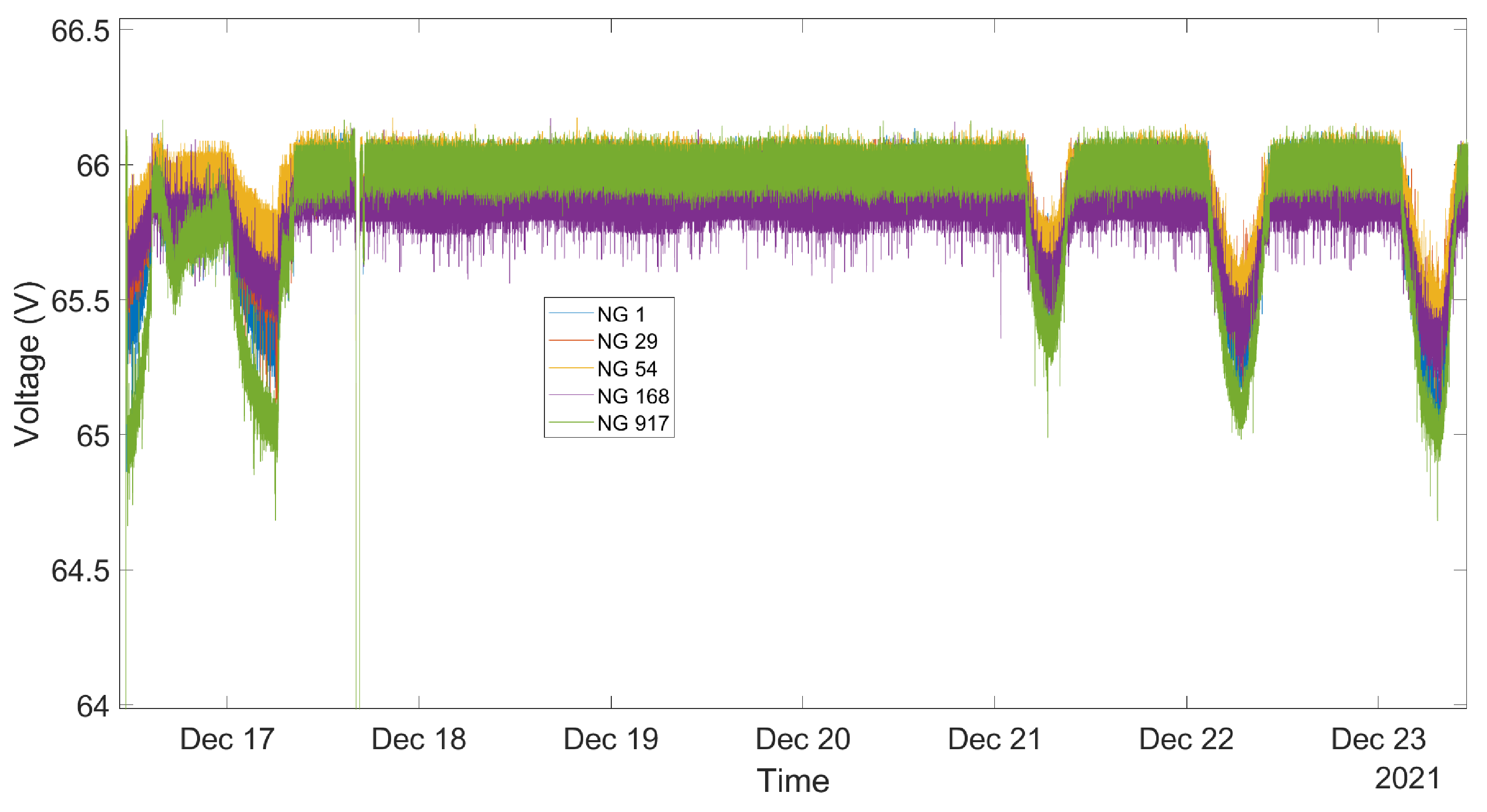
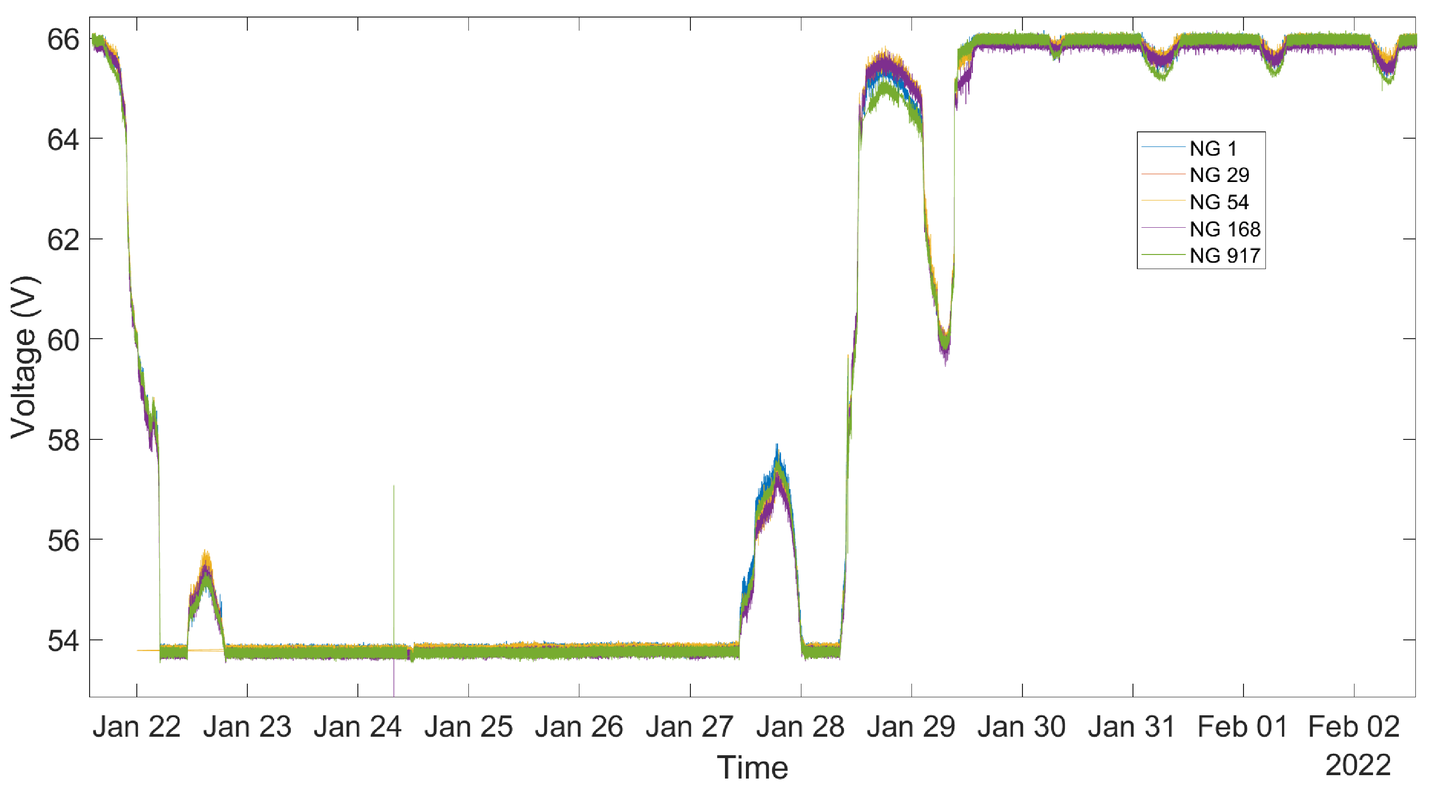
  • For the following 3 days, NG 917 is self-sufficient and is therefore not requesting any support from the microgrid, hence a DC bus voltage stable at 66 V.
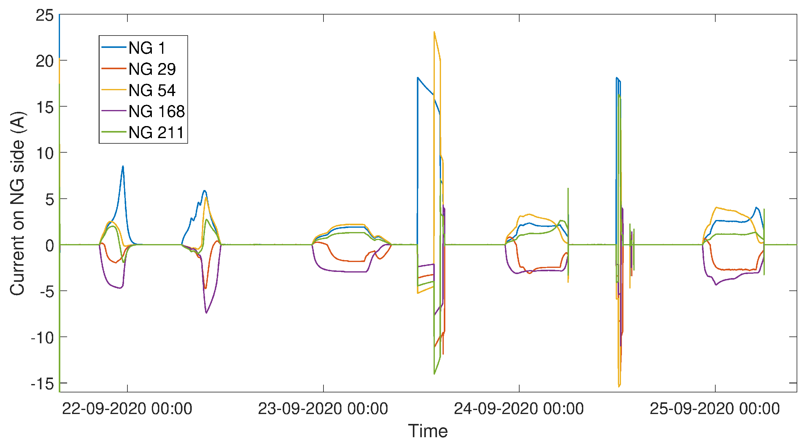
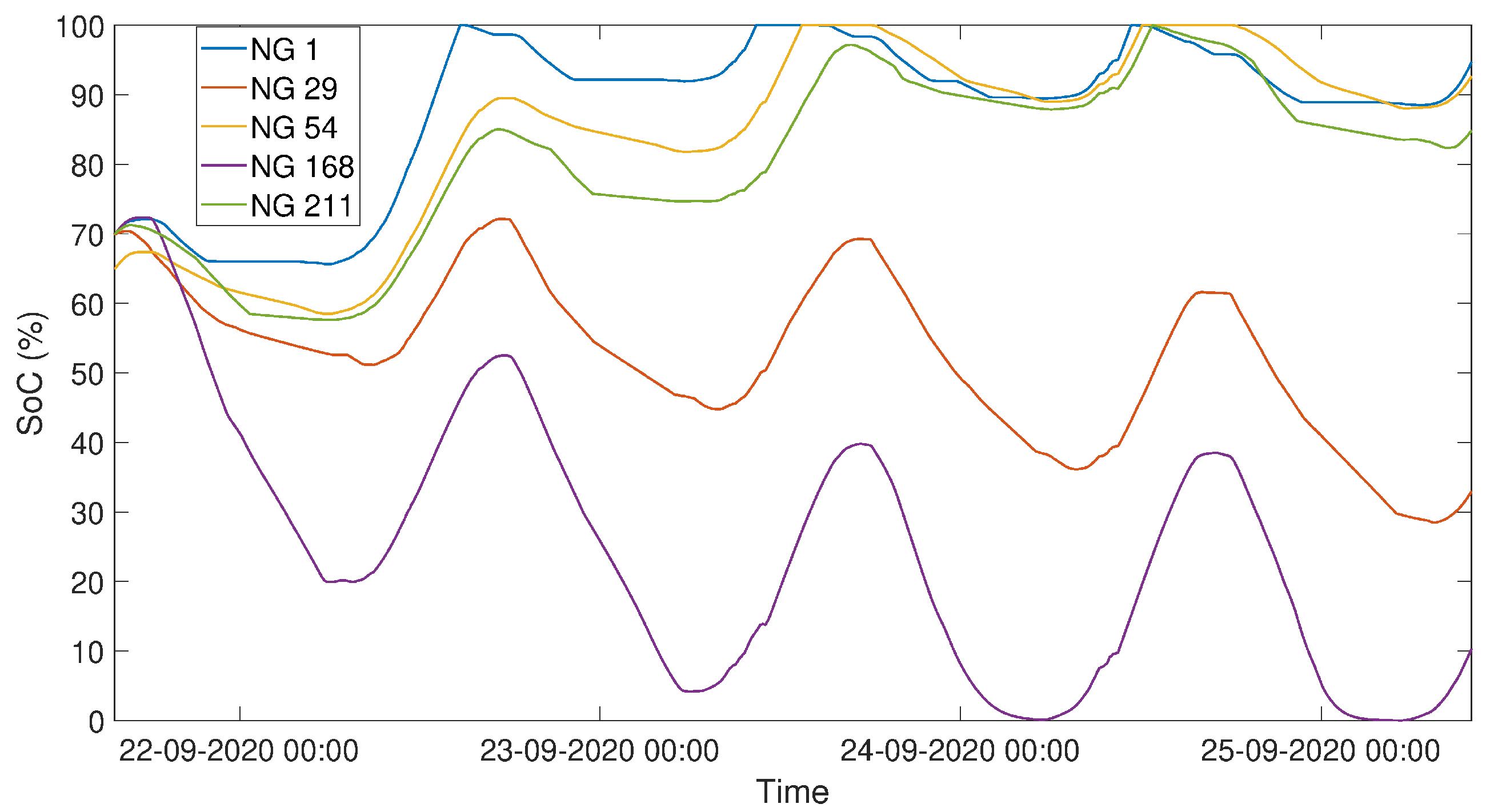
  • Then, NG 917 reaches again low levels of SoC, below 80%, and starts to absorb current from the microgrid. Therefore, the DC bus voltage diminishes and the 4 other NGs inject to support NG 917. For 3 consecutive days, the 4 other NGs manage to bring NG 917 SoC back to 80% without leaving the strong SoC zone.
Those results also prove the importance of the topology of the microgrid, especially regarding meshed or radial topology. The microgrid was launched with a radial topology with the line between NG 54 and NG 917 opened (see Figure 29). After one day of operation, on the afternoon of 17 December, the microgrid was briefly stopped to close the line to create a meshed topology (at the time where the SoCs and the DC bus voltage collapse on Figure 31 and Figure 32). The results show that NG 54 did not support much NG 917 during the first day, as the electric distance between NG 917 and NG 54 was big. Due to the long electrical distance between the point of consumption (i.e., NG 917) and NG 54 and the associated voltage drops on the cables, there were a high DC bus voltage at NG 54. This makes the interconnection module of NG 54 consider that there were no other NGs to support. When the topology was set to be meshed once again, NG 54, one of the strongest NG on the microgrid, supported NG 917 the most, as can be seen in Figure 30 from 21 December. This result illustrates the impact of the topology of the microgrid on the power flows between the nanogrids. If possible, strong and weak NGs must be equally disseminated within the microgrid to balance it.
Figure 33, Figure 34 and Figure 35 show the operation of the microgrid for 10 days in a row during a period of high rains and storms in Madagascar. The following steps are illustrated:
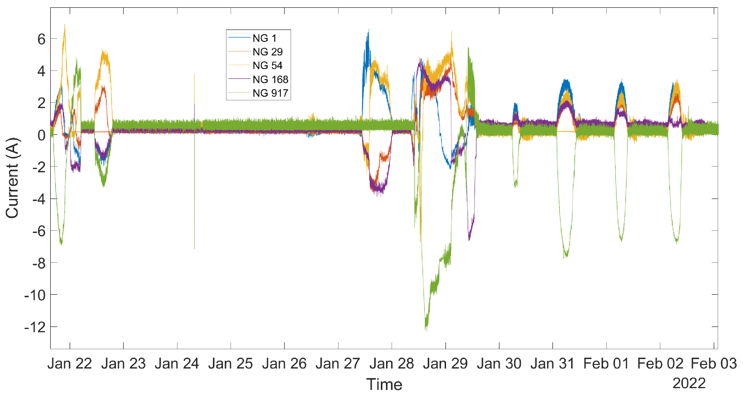
  • The microgrid global level of energy quickly collapses due to the total absence of sun, and then the DC bus voltage stabilizes at 54 V for 5 days. NG 917 even disconnects from the microgrid due to low battery voltage from 24 to 28 January.
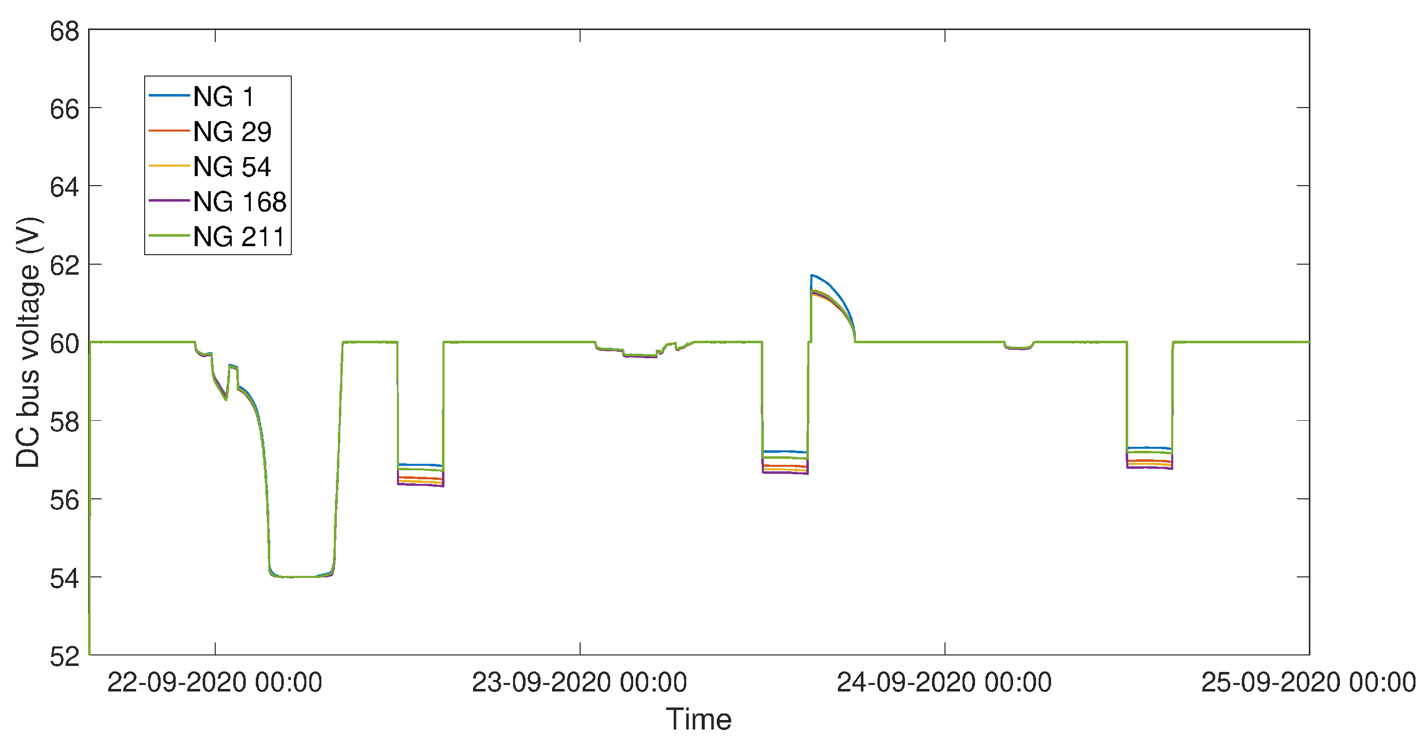
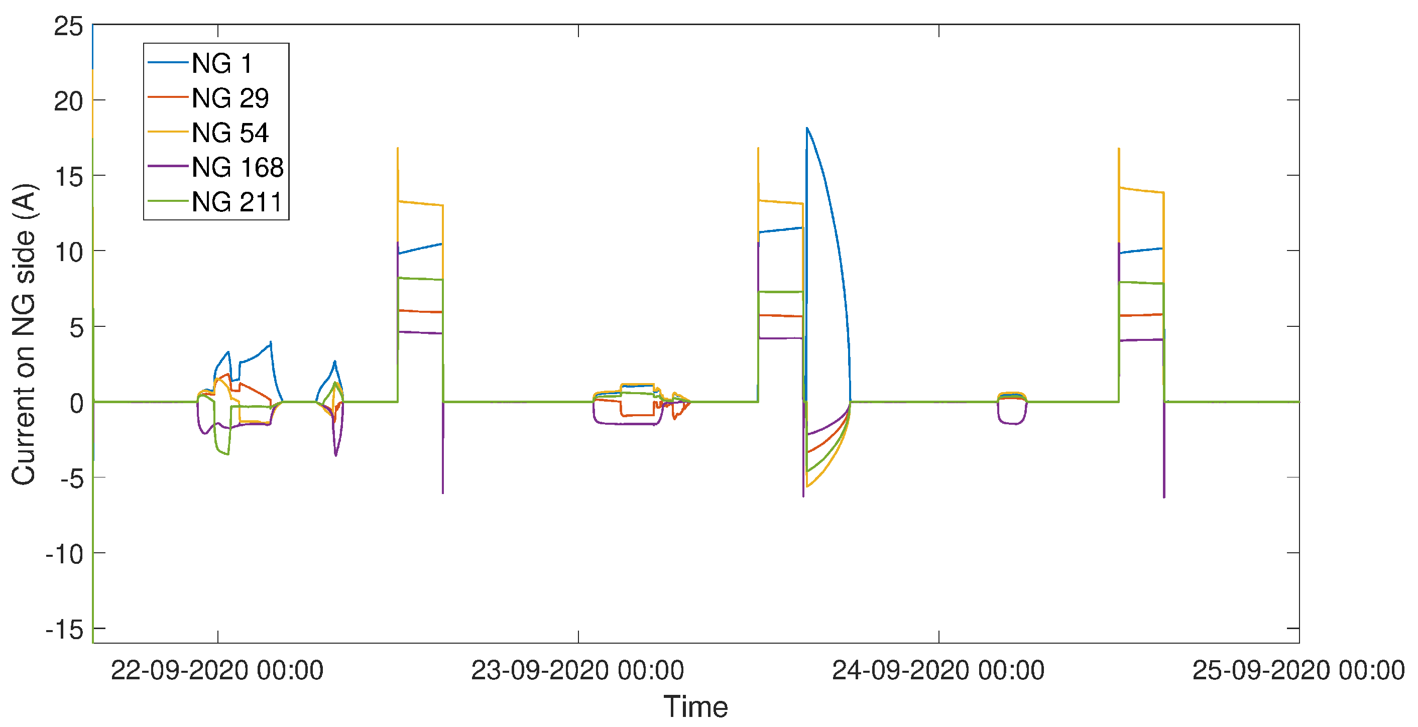
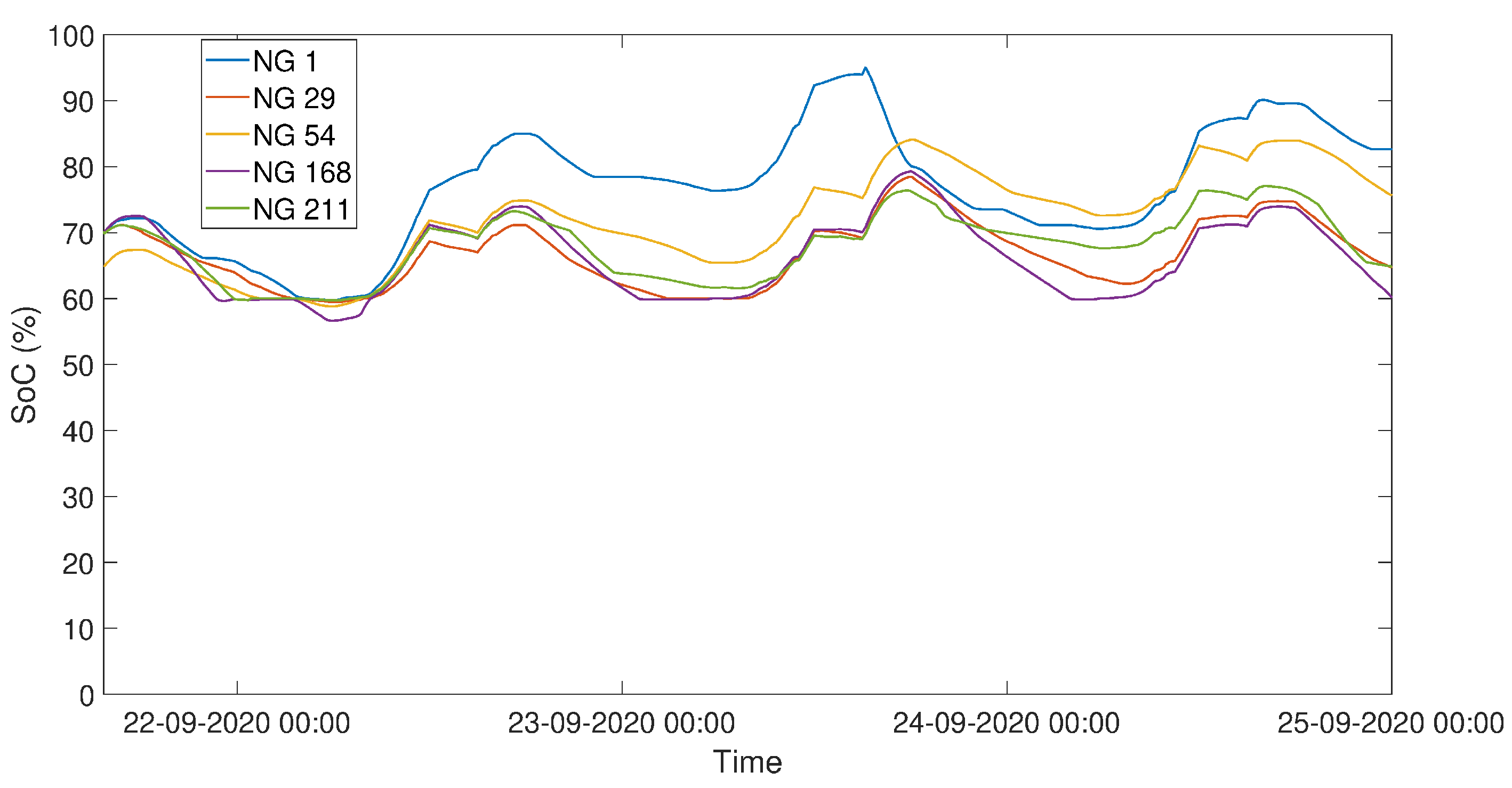
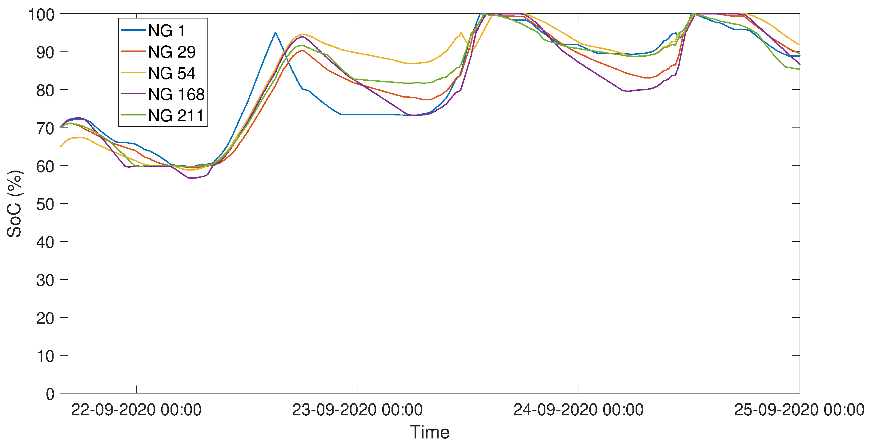
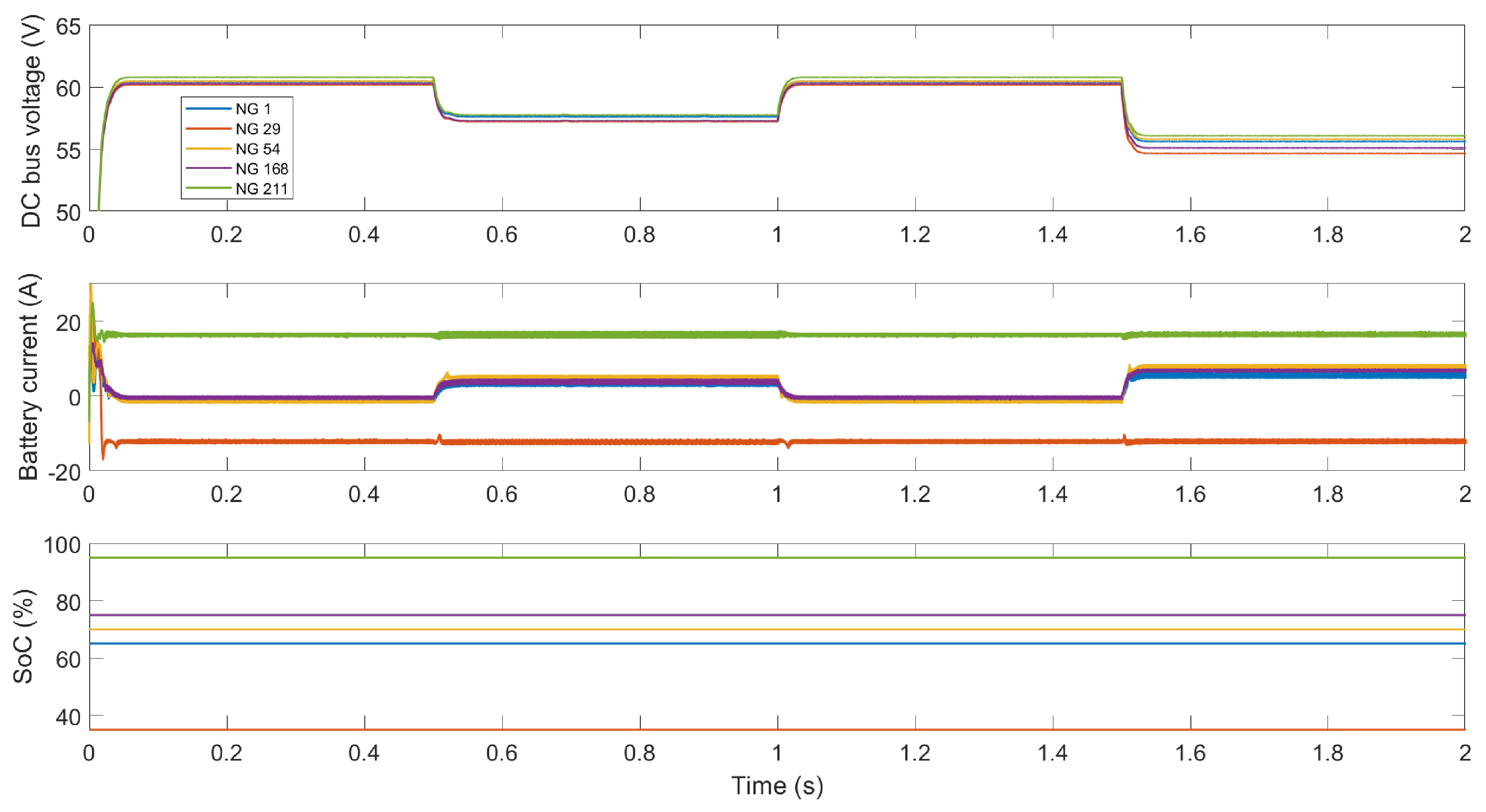
  • When the solar panels start to produce again, NGs 1 and 54, the first NGs to reach medium level of SoC, support the other NGs connected i.e., NGs 29 and 168.
  • When NG 917 reconnects to the microgrid on the 28th, all the other NGs strongly support NG 917 to bring its SoC back to the medium and then to the high zone.
  • The following days, all the NGs support NG 917 similarly to Figure 30.
Those results demonstrate the relevance of a microgrid in case of extreme weather events, where the first charged NGs can support the other weak ones. It would be even better with more NGs connected on the microgrid. Note that the estimated SoCs are unreliable from 23 to 26 January due to very low battery SoCs (especially for NG 917, which experienced blackout).
The microgrid in Ambohimena is still in operation 6 months after the installation, without any major issue. This validation of the microgrid design is an important step and offers a technical proof of concept for the electrification model advocated by Nanoé.

6. Remarks and Discussion

6.1. Field Test Feedback

The field deployment of a first DC microgrid with decentralized storage and production has brought insightful feedback both on the installation and on the operation of the DC microgrid.
During the installation phase, the location of the electric poles and the passage of the cables were difficult to define. The maximum distance between two electric poles was set at 50 m, from the field experience, due to the difficulty to tense the cables manually for higher distances. Furthermore, the installation of the interconnection modules has underlined the major importance of its user friendliness and of the robustness of all the cabling parts (power cables as well as peripherals), which were the origin of most installation problems. Last but not least, the inhabitants of Ambohimena welcomed the microgrid installation with great excitation and curiosity, which helped the installation process, and overall enhanced the sustainability of the proposed microgrid [14].
The first weeks of operation of the microgrid highlighted four main problems, i.e., the protection scheme, the starting procedure for the microgrid, the SoC estimator and the calibration of the interconnection modules. Firstly, the different tests carried out show the importance of carefully tuning the protection scheme. An interconnection module disconnects itself from the microgrid after a few 80 μs time-steps, where dangerous events are recorded (over-voltage, over-current, low or high battery voltage, etc.) and then tries to reconnect to check if the errors are still present. The number of such time steps and the delays between subsequent reconnections must be carefully adapted to avoid inappropriate disconnection and increase the automation of the operation of the microgrid. This protection logic was actually tested on the field as one interconnection module broke during the first weeks of operation due to a misconnection provoking an arm short-circuit. The other interconnection modules quickly disconnected themselves from the microgrid as the DC bus voltage suddenly dropped to a low value. After a minute of waiting, they tried to reconnect and they successfully set the microgrid back in operation as the broken interconnection module circuit breaker had opened. No such incidents happened again up to August 2022.
In addition, the protection scheme must be adapted to the smooth start-up procedure. Indeed, without the smooth start-up procedure presented in Figure 21 being implemented, the start-up of the microgrid was triggering the protection scheme of the interconnection module because of the large initial inrush current due to the fact that the first interconnection module to start must charge all the DC bus capacitance and energize all the cables. However, with the smooth start-up procedure implemented, the DC bus voltage slowly increases to the reference from the control algorithm presented in Figure 7 (i.e., 54 V, 60 V or 66 V depending on the SoC of the first NG to connect) as can be seen in Figure 21, and the interconnection module triggered a low DC bus voltage protection alert. Thus, the protection scheme was also adapted to allow for a larger deviation from the standard voltage range when being the first interconnection module to start (i.e., when detecting a voltage close to 0 V on the DC bus).
Regarding the SoC estimator of the interconnection modules, it was initially of poor precision and reliability, which impacted the operation of the microgrid in its early stage. If an interconnection module estimates a high SoC for a discharged battery, it will continue to inject current on the microgrid, which will further discharge the battery until its voltage reaches a low protection limit, or vice versa for an estimated low SoC for a charged battery. Therefore, particular attention must be paid to the precision of the SoC estimator which is at the input of the control algorithm. On-field improvements were brought to the SoC estimator to increase its precision and reliability, even if it remains of poor precision at low SoC.
Furthermore, due to the unavailability of high precision voltage and current sensors in Nanoé’s facilities in Madagascar, the interconnection modules were not well calibrated in terms of voltage and current. This provokes the voltage oscillations observed in Figure 32 and Figure 35, as the different interconnection modules do not agree on a voltage level, due to differences in measurement errors.
Last but not least, communal load operation was also successfully tested with the use of a simple power resistor for a short time. Each NG was powering the communal load with respect to their SoC and to their distance to the communal load. This first step with a straightforward communal load validates one of the main reasons to build a village-wide microgrid, i.e., the installation of productive loads of higher power.

6.2. Perspective and Future Works

The difficulties encountered to choose where and how to install the electric poles and the cables highlight the need to study the DC microgrid planning to identify the optimal topology to connect NGs. In addition, with the possibility of connecting NGs within a village-wide microgrid, the optimal allocation of hardware resources (i.e., solar panel, batteries and communal loads) must be determined to increase the economic sustainability of the microgrid project by decreasing the amount of hardware resources installed within a microgrid. Future works will therefore focus on the development of optimisation algorithms for decision aids regarding the installation and operation of such DC microgrids.
In addition, a second version of the interconnection module is under development with the objective of interconnecting more NGs by 2023. This interconnection module and especially the bidirectional DC-DC converter must result from a technical and economical optimization study. In particular, as the microgrid is still under development and open to changes, it is of particular interest to study how the specifications of the microgrid (i.e., DC bus voltage level, inertia, power rating) and the DC-DC converter are intertwined. This interconnection module must also be more user friendly and enable different use cases, e.g., communal loads based on DC motors or NGs without battery.
Furthermore, due to the high dependence of the microgrid operation on the SoC estimation, particular attention will be paid on the development of an in-house SoC estimator through the modified Coulomb counting method or Kalman filter to increase the precision of the SoC estimation of lead–acid batteries. A modification of the proposed control algorithm for the DC microgrid, based on the battery voltage instead of its SoC, is also under study.
Finally, the stability of DC microgrids with decentralized production and storage must be investigated to guarantee the proper operation of the DC microgrid and to identify which factors (topology, control algorithm, DC bus capacitance, etc.) impact the most its stability and how this can influence the design of the interconnection module.

7. Conclusions

This paper presents the successful development of a DC microgrid with decentralized production and storage designed for the progressive building of electric infrastructure for rural Africa, from software simulations and lab test bench to field deployment in Madagascar. Firstly, an architecture and a control algorithm were designed through software simulations on Matlab-Simulink. Then, a lab test-bench enabled to thoroughly and experimentally validate the proposed microgrid. Finally, after the in-house development of an interconnection module, a first microgrid interconnecting five nanogrids was successfully installed in Ambohimena in Madagascar, completing the whole development of a DC microgrid from the lab to the field.
This technical and scientific accomplishment is an important milestone for Nanoé’s electrification model which validates its technological approach and highlights the importance of public–private partnership to tackle rural electrification challenges. This work concludes the first step of DC microgrid development for Nanoé by giving a proof of concept for the proposed microgrid. A second mission in Madagascar is planned for early 2023 to interconnect more NGs in Ambohimena with an enhanced interconnection module to demonstrate the capacity of such a microgrid solution to operate at a larger scale.
In addition, this first DC microgrid pilot opens up a myriad of social, economic and technical possibilities that must be thoroughly analyzed, and it is the belief of the authors that the described electrification model and microgrid solution could be replicated in many other developing countries. However, before installing plenty of microgrids in numerous villages, it is crucial to perform DC microgrid planning and stability studies to ensure the proper and efficient installation and operation of the proposed solutions. Technology-wise, particular efforts should be directed toward the development of a precise and reliable SoC estimator, which is at the input of the microgrid operation. Lastly, interviews must be conducted with possible microgrid end users in Madagascar to precisely fit the proposed solution to the expectations of the target communities and increase the socio-economic impact of the proposed microgrid. This will be the object of future works.

Author Contributions

Conceptualization, L.R., D.F., M.-C.A.-H., B.R. and N.S.; methodology, L.R., D.F., M.-C.A.-H., B.R. and N.S.; software, L.R. and C.B.; validation, L.R., C.B., S.A.R., J.O.R. and A.E.B.; formal analysis, L.R.; investigation, L.R., S.A.R., J.O.R. and A.E.B.; resources, L.R.; data curation, L.R.; writing—original draft preparation, L.R.; writing—review and editing, L.R., D.F., M.-C.A.-H., B.R. and N.S.; visualization, L.R.; supervision, D.F., M.-C.A.-H., B.R. and N.S.; project administration, B.R. and N.S.; funding acquisition, B.R. and N.S. All authors have read and agreed to the published version of the manuscript.

Funding

This research, a part of the LEAP-RE project, was funded by the European Union’s Horizon 2020 research and innovation program under grant agreement N° 963530. The APC was funded by the G2ELab.

Institutional Review Board Statement

Not applicable.

Informed Consent Statement

Not applicable.

Data Availability Statement

Not applicable.

Conflicts of Interest

The authors declare no conflict of interest. This paper reflects only the authors’ view and the European Climate, Infrastructure and Environment Executive Agency and the European Commission are not responsible for any use that may be made of the information it contains.

Acronyms

DCDirect Current
DoDDepth of Discharge
NGNanogrid
PWM  Pulse Width Modulation
SHSSolar Home System
SoCState of Charge
UIUser Interface

References

  1. United Nation 17 Goals. United Nations (UN). 2021. Available online: https://sdgs.un.org/goals (accessed on 12 September 2022).
  2. World Energy Outlook (WEO). International Energy Agency (IEA). 2021. Available online: https://www.iea.org/reports/world-energy-outlook-2021 (accessed on 12 September 2022).
  3. Nasir, M.; Khan, H.A.; Zaffar, N.A.; Vasquez, J.C.; Guerrero, J.M. Scalable solar DC microgrids. IEEE Electrif. Mag. 2018, 6, 63–72. [Google Scholar] [CrossRef]
  4. Groh, S.; Philipp, D.; Lasch, B.E.; Kirchhoff, H. Swarm Electrification: Investigating a Paradigm Shift Through the Building of Microgrids Bottom-up. In Decentralized Solutions for Developing Economies; Springer: Cham, Switzerland, 2015; Chapter 1; pp. 25–44. [Google Scholar]
  5. World Energy Outlook (WEO). The Heartland Institude. 2011. Available online: https://www.heartland.org/publications-resources/publications/energy-for-all-financing-access-for-the-poor (accessed on 12 September 2022).
  6. Moner-Girona, M.; Bódis, K.; Morrissey, J.; Kougias, I.; Hankins, M.; Huld, T.; Szabó, S. Decentralized rural electrification in Kenya: Speeding up universal energy access. Energy Sustain. Dev. 2019, 52, 128–146. [Google Scholar] [CrossRef]
  7. Nanoé Presentation Website. 2022. Available online: https://www.nanoe.net/en/ (accessed on 12 September 2022).
  8. Multi-Tier Framework. Sustainable Energy for All. 2016. Available online: https://www.seforall.org/events/multi-tier-framework-for-tracking-energy-access-update-on-the-framework-design-and (accessed on 12 September 2022).
  9. Pelz, S.; Pachauri, S.; Groh, S. A critical review of modern approaches for multidimensional energy poverty measurement. Wiley Interdiscip. Rev. Energy Environ. 2018, 7, e304. [Google Scholar] [CrossRef]
  10. G2ELab Presentation Website. 2022. Available online: https://g2elab.grenoble-inp.fr/en (accessed on 12 September 2022).
  11. Nasir, M.; Jin, Z.; Khan, H.A.; Zaffar, N.A.; Vasquez, J.C.; Guerrero, J.M. A Decentralized Control Architecture Applied to DC Nanogrid Clusters for Rural Electrification in Developing Regions. IEEE Trans. Power Electron. 2019, 34, 1773–1785. [Google Scholar] [CrossRef]
  12. Nasir, M.; Zaffar, N.A.; Khan, H.A. Analysis on Central and Distributed Architectures of Solar powered DC Microgrids. In Proceedings of the 2016 Clemson University Power Systems Conference (PSC), Clemson, SC, USA, 8–11 March 2016; pp. 1–6. [Google Scholar]
  13. Nasir, M.; Iqbal, S.; Khan, H.A.; Vasquez, J.C.; Guerrero, J.M. Sustainable Rural Electrification Through Solar PV DC Microgrids—An Architecture-Based Assessment. Processes 2020, 8, 1417. [Google Scholar] [CrossRef]
  14. Boche, A.; Foucher, C.; Villa, L.F.L. Understanding Microgrid Sustainability: A Systemic and Comprehensive Review. Energies 2022, 15, 2906. [Google Scholar] [CrossRef]
  15. Nasir, M.; Anees, M.; Khan, H.A.; Guerrero, J.M. Dual-loop control strategy applied to the cluster of multiple nanogrids for rural electrification applications. IET Smart Grid 2019, 2, 327–335. [Google Scholar] [CrossRef]
  16. Li, D.; Ho, C.N.M. A Module-Based Plug-n-Play DC Microgrid with Fully Decentralized Control for IEEE Empower a Billion Lives Competition. IEEE Trans. Power Electron. 2021, 36, 1764–1776. [Google Scholar] [CrossRef]
  17. Nasir, M.; Anees, M.; Khan, H.A.; Khan, I.; Xu, Y.; Guerrero, J.M. Integration and Decentralized Control of Standalone Solar Home Systems for Off-Grid Community Applications. IEEE Trans. Ind. Appl. 2019, 55, 7240–7250. [Google Scholar] [CrossRef]
  18. Li, D.; Man Ho, C.N.; Kingman Siu, K.; Pokharel, M. A Module-Based Hierarchical Microgrid with a Bottom-Up Building Architecture for Rural Electrification. In Proceedings of the IEEE Applied Power Electronics Conference and Exposition—APEC2020, New Orleans, LO, USA, 15–19 March 2020; pp. 3384–3390. [Google Scholar]
  19. Samende, C.; Bhagavathy, S.M.; McCulloch, M. State of Charge Based Droop Control for Coordinated Power Exchange in Low Voltage DC Nanogrids. In Proceedings of the International Conference on Power Electronics and Drive Systems, Toulouse, France, 9–12 July 2019. [Google Scholar]
  20. Samende, C.; Bhagavathy, S.M.; Gao, F.; McCulloch, M. Decentralized Voltage Control for Efficient Power Exchange in Interconnected DC Clusters. IEEE Trans. Sustain. Energy 2021, 12, 103–115. [Google Scholar] [CrossRef]
  21. Lu, X.; Sun, K.; Guerrero, J.M.; Vasquez, J.C.; Huang, L. Double-quadrant state-of-charge-based droop control method for distributed energy storage systems in autonomous DC Microgrids. IEEE Trans. Smart Grid 2015, 6, 147–157. [Google Scholar] [CrossRef]
  22. Mosayebi, M.; Sadeghzadeh, S.M.; Khooban, M.H.; Guerrero, J.M. Decentralised non-linear I-V droop control to improve current sharing and voltage restoration in DCNG clusters. IET Power Electron. 2020, 13, 248–255. [Google Scholar] [CrossRef]
  23. Diaz, N.L.; Dragicevic, T.; Vasquez, J.C.; Guerrero, J.M. Intelligent distributed generation and storage units for DC microgrids—A new concept on cooperative control without communications beyond droop control. IEEE Trans. Smart Grid 2014, 5, 2476–2485. [Google Scholar] [CrossRef]
  24. Dragičević, T.; Lu, X.; Vasquez, J.C.; Guerrero, J.M. DC Microgrids—Part I: A Review of Control Strategies and Stabilization Techniques. IEEE Trans. Power Electron. 2016, 31, 4876–4891. [Google Scholar]
  25. Meng, L.; Shafiee, Q.; Trecate, G.F.; Karimi, H.; Fulwani, D.; Lu, X.; Guerrero, J.M. Review on Control of DC Microgrids and Multiple Microgrid Clusters. IEEE J. Emerg. Sel. Top. Power Electron. 2017, 5, 928–948. [Google Scholar]
  26. Nasir, M.; Khan, H.A.; Hussain, A.; Mateen, L.; Zaffar, N.A. Solar PV-based scalable DC microgrid for rural electrification in developing regions. IEEE Trans. Sustain. Energy 2018, 9, 390–399. [Google Scholar] [CrossRef]
  27. Madduri, P.A.; Poon, J.; Rosa, J.; Podolsky, M.; Brewer, E.A.; Sanders, S.R. Scalable DC Microgrids for Rural Electrification in Emerging Regions. IEEE J. Emerg. Sel. Top. Power Electron. 2016, 4, 1195–1205. [Google Scholar] [CrossRef]
  28. Liptak, S.; Miranbeigi, M.; Kulkarni, S.; Jinsiwale, R.; Divan, D. Self-Organizing NanoGrid (SONG). In Proceedings of the 2019 IEEE Decentralized Energy Access Solutions Workshop (DEAS), Atlanta, GA, USA, 5–7 February 2019; pp. 206–212. [Google Scholar]
  29. Saha, S.S.; Janko, S.; Johnson, N.G.; Podmore, R.; Riaud, A.; Larsen, R. A universal charge controller for integrating distributed energy resources. In Proceedings of the GHTC 2016—IEEE Global Humanitarian Technology Conference: Technology for the Benefit of Humanity, Conference Proceedings, Seattle, WA, USA, 13–16 October 2016; pp. 459–465. [Google Scholar]
  30. Kirchhoff, H.; Strunz, K. Key drivers for successful development of peer-to-peer microgrids for swarm electrification. Appl. Energy 2019, 244, 46–62. [Google Scholar] [CrossRef]
  31. O’Neill-Carrillo, E.; Jordan, I.; Irizarry-Rivera, A.; Cintron, R. The long road to community microgrids: Adapting to the necessary changes for renewable energy implementation. IEEE Electrif. Mag. 2018, 6, 6–17. [Google Scholar] [CrossRef]
  32. Dragičević, T.; Lu, X.; Vasquez, J.C.; Guerrero, J.M. DC Microgrids—Part II: A Review of Power Architectures, Applications, and Standardization Issues. IEEE Trans. Power Electron. 2016, 31, 3528–3549. [Google Scholar] [CrossRef]
  33. Shafiee, Q.; Dragicevic, T.; Andrade, F.; Vasquez, J.C.; Guerrero, J.M. Distributed consensus-based control of multiple DC-microgrids clusters. In Proceedings of the IECON (Industrial Electronics Conference), Dallas, TX, USA, 29 October–1 November 2014; pp. 2056–2062. [Google Scholar]
  34. Shafiee, Q.; Dragičević, T.; Vasquez, J.C.; Guerrero, J.M. Hierarchical control for multiple DC-microgrids clusters. IEEE Trans. Energy Convers. 2014, 29, 922–933. [Google Scholar] [CrossRef] [Green Version]
  35. Simscape Electrical Matlab Toolbox. Mathworks. 2022. Available online: https://fr.mathworks.com/products/simscape-electrical.html (accessed on 12 September 2022).
  36. Solar Radiation Data. SoDa Pro. 2022. Available online: https://www.soda-pro.com/ (accessed on 12 September 2022).
  37. Richard, L.; Derbey, A.; Frey, D.; Alvarez-Hérault, M.C.; Raison, B. Experimental Design of Solar DC Microgrid for the Rural Electrification of Africa. In Proceedings of the PCIM Europe, Nurnberg, Germany, 10–12 May 2022; pp. 1–10. [Google Scholar]
  38. LabVIEW Presentation Website. National Instruments. 2021. Available online: https://www.ni.com/en-za/shop/labview.html (accessed on 12 September 2022).
Figure 1. Schematic of a nanogrid installation.
Energies 15 06727 g001
Figure 2. Progressive building of power infrastructure.
Energies 15 06727 g002
Figure 3. Geographical distribution of the nanogrids of Ambohimena (black dots: nanogrids, blue lines: the microgrid installed in November 2021, green lines: extension project for Ambohimena).
Energies 15 06727 g003
Figure 4. Averaged and maximal depth of discharge of the nanogrids in Ambohimena over 3 months.
Energies 15 06727 g004
Figure 5. Size reduction of the battery park of Ambohimena with increased Depth of Discharge.
Energies 15 06727 g005
Figure 6. Configuration of the proposed microgrid.
Energies 15 06727 g006
Figure 7. Decentralized and communication-free control algorithm.
Energies 15 06727 g007
Figure 8. Topology of the simulated microgrid.
Energies 15 06727 g008
Figure 9. Evolution of the DC bus voltage—microgrid connection mode.
Energies 15 06727 g009
Figure 10. Evolution of the currents exchanged between the NGs—microgrid connection mode.
Energies 15 06727 g010
Figure 11. Evolution of the SoC of the NGs—microgrid connection mode.
Energies 15 06727 g011
Figure 12. Evolution of the SoC of the NGs without a microgrid.
Energies 15 06727 g012
Figure 13. Evolution of the DC bus voltage with a 1500 Wh communal load—communal load operation.
Energies 15 06727 g013
Figure 14. Evolution of the currents exchanged between the NGs with a 1500 Wh communal load—communal load operation.
Energies 15 06727 g014
Figure 15. Evolution of the SoC of the NGs with a 1500 Wh communal load—communal load operation.
Energies 15 06727 g015
Figure 16. Evolution of the SoC of the NGs without a communal load.
Energies 15 06727 g016
Figure 17. Evolution of the DC bus voltage, the battery currents and the SoCs of the NGs for stability analysis with sudden connection and disconnection of a communal load.
Energies 15 06727 g017
Figure 18. Schematic of the lab test bench.
Energies 15 06727 g018
Figure 19. Test bench of the microgrid interconnecting 3 nanogrids.
Energies 15 06727 g019
Figure 20. Schematic of the bidirectional converter.
Energies 15 06727 g020
Figure 21. Initial inrush current (in green) and DC bus voltage (in pink) without and with the smooth start-up procedure.
Energies 15 06727 g021
Figure 22. Lab prototype of the converter.
Energies 15 06727 g022
Figure 23. Evolution of the DC bus voltage, the SoCs and the currents exchanged between the converters at different operating points.
Energies 15 06727 g023
Figure 24. Impact of a communal load on the microgrid power flows.
Energies 15 06727 g024
Figure 25. Power card of the interconnection module.
Energies 15 06727 g025
Figure 26. Command card of the interconnection module.
Energies 15 06727 g026
Figure 27. Local mounting of the interconnection modules and cable set-up in Ambohimena.
Energies 15 06727 g027
Figure 28. Installation of the interconnection modules in Ambohimena and cable connection at the top of a pole.
Energies 15 06727 g028
Figure 29. Schematic of the microgrid installed.
Energies 15 06727 g029
Figure 30. Exchanged currents on the microgrid deployed in Ambohimena.
Energies 15 06727 g030
Figure 31. Evolution of the measured SoCs of the interconnected NGs.
Energies 15 06727 g031
Figure 32. Evolution of the DC bus voltage on Ambohimena microgrid.
Energies 15 06727 g032
Figure 33. Exchanged currents on the microgrid deployed in Ambohimena during a rainy period.
Energies 15 06727 g033
Figure 34. Evolution of the measured SoCs of the interconnected NGs during a rainy period.
Energies 15 06727 g034
Figure 35. Evolution of the DC bus voltage on Ambohimena microgrid during a rainy period.
Energies 15 06727 g035
Table 1. Parameters of the proposed control algorithm.
Parameters V ref V min V max SoC max SoC min SoC lim R d α C bat C max I rated
Value60 V54 V66 V80%60%30%0.51/3Capacity of the NG battery180 Ah C b a t 10
Table 2. Parameters of the developed converter and test bench.
ParametersSymbolValue
Number of armsN2
Power inductor L 1 , L 2 360 μ H
DC bus capacitance C M G 3 mF
Rated current I m a x 18 A
Input voltage V b a t 10–29 V
Power rating P c o n v 500 W
Switching frequency f s w 25 kHz
Number of converters N c 3
Lineic resistance of the electric cable R l 1.465 Ω /km
Lineic inductance of the electric cable L l 337 μ H/km
Proportional and integral parameters k p , k i 0.005, 0.001
PI integration step δ t 200 μ s
Publisher’s Note: MDPI stays neutral with regard to jurisdictional claims in published maps and institutional affiliations.

