

Research on Demand Analysis and Optimal Allocation of Rail Transit Hybrid Energy Storage Based on the Electric Traction Model

Electrical and Control Engineering College, North China University of Technology, Beijing 100144, China
*
Author to whom correspondence should be addressed.
Energies 2022, 15(19), 6970; https://0-doi-org.brum.beds.ac.uk/10.3390/en15196970
Submission received: 4 August 2022
/
Revised: 28 August 2022
/
Accepted: 30 August 2022
/
Published: 23 September 2022
(This article belongs to the Special Issue Advanced Management Techniques for Energy Storage Systems)
Abstract
:With the development of power transmission technology and power electronics, electrified railroads are widely used and pose a great challenge for the power grid. Hybrid energy storage integrates different advantages of multiple energy storage and can cope with the complex energy situation of rail transit. The complementary characteristics of lithium batteries and flywheels in terms of techno-economic indicators make them the main form of hybrid energy storage. In this paper, we analyze the power demand during train operation by studying the electromechanical characteristics of the rail transit traction process. On this basis, hybrid energy storage is configured to meet the power demand, and particle swarm optimization is chosen as the solution tool to perform the capacity configuration of lithium battery and flywheel in this paper. Finally, this paper proves the feasibility of the proposed theory by arithmetic example analysis, and it is shown that the proposed scheme can achieve a high percentage of energy reuse and low application cost.
1. Introduction
New energy technologies, represented by energy storage, are widely used in rail transport. Along with the development of transport electrification, energy storage has gradually become an important crossover direction and a hot technology growth point for the transport industry and the power industry. On the one hand, the power regulation capability of energy storage can improve the power quality of the traction power supply system and reduce the impact of the train operation on the power grid. On the other hand, the capacity characteristics of energy storage can provide support for energy recovery and regenerative braking technologies for rail transportation, providing a theoretical basis for energy-efficient operation in multiple scenarios of rail transportation [1,2,3].
Hybrid energy storages are energy storage systems that integrate a variety of energy storages with different characteristics. Energy storage devices can be classified by their external characteristics into energy-based energy storage and power-based energy storage. Energy-based energy storage has a high capacity density and can be used as a stable source of energy over a long period of time. Power-based storage has a high power density and can provide instantaneous high power support for the system. For high energy consumption and high-impact loads such as rail transport, hybrid energy storage can be configured to meet the energy requirements in different phases of operation [4,5,6]. Now, the research on hybrid energy storage for rail transit is mainly focused on two aspects: power conditioner and energy storage siting.
The power conditioner is a technology that uses power electronics to achieve phase balancing in traction substations [7,8,9]. Traction substations in rail transit need to supply power to both the upward and downward directions, and the imbalance of loads on both sides can lead to phase imbalance in the power system. The power conditioner achieves this by linking the two sides of the substation via back-to-back converters and equipping the DC bus side with energy storage units to balance the energy on both sides. The topology and the modulation strategy of the power conditioner have been extensively studied [5,10,11]. Energy storage is configured within this system according to demand, and the energy from the storage is allocated through energy management strategies according to the power imbalance on both sides of the substation.
Energy storage siting under traction power supply systems is another extensive area of research. The research is based on deep mining of historical data of traction power supply systems and substations. The optimal allocation of energy storage is obtained by solving optimization algorithms such as neural nets, genetic algorithms and nonlinear programming [12,13,14]. This type of research usually chooses economy and power quality as the optimization objectives and obtains the corresponding index characteristic gains through the configuration of hybrid energy storage. By combining control theories such as the economic operation of power systems, this type of research achieves the management and allocation of energy storage on a constant capacity basis over a full-day timescale.
The two directions above analyze the application of hybrid energy storage in rail transport at the micro-device level and at the macro-system level, respectively. In this process, trains in rail transport are replaced by transient power states and periodic regular loads, respectively. The lack of analysis of the electromechanical and load characteristics of rail transport in the studies that have been carried out makes the hybrid energy storage in the relevant studies lacking in conjunction with rail transport.
In this paper, a hybrid energy storage capacity optimization approach is proposed which is based on the electric traction model and achieves energy storage capacity optimization at the rail transit operating timescale. This paper firstly achieves a static characterization of the electromechanical properties of the rail traction process by modeling the dynamics model, the traction motor model and the traction power supply system model involved in the rail traction process. Afterward, the dynamic solution of the traction process is used to derive the system energy demand during the operation. Finally, the hybrid energy storage is allocated to the power and energy requirements of the train during its journey by means of an economy-based optimization algorithm. The approach in this paper achieves an economic capacity optimization of the hybrid energy storage, in which the generated energy storage power allocation sequence can also provide a basis for a control strategy after the energy storage has been built.
2. Modeling the Electromechanical Characteristics of Rail Traction
The energy consumption of rail transport is influenced by many factors. One of the main influences is the electromechanical characteristics of the train. This section focuses on the characterization of the train’s motion through the development of a train dynamics model, a traction motor model and a traction network model.
2.1. Dynamics Model for Trains
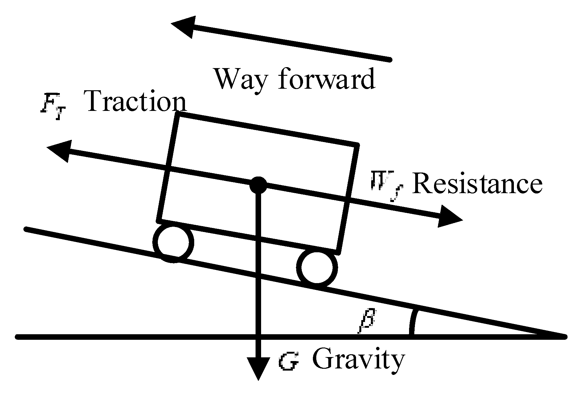
The force model of a train in a rail system can be represented with the front and rear axles in the same plane, as shown in Figure 1.
The train is subject to gravity, ground support, traction and drag. The traction and drag forces along the train’s direction of travel are the main factors affecting the dynamic characteristics. The equation of motion of the train is shown as follows:
where M is the overall mass of the train, λ is the slew correction factor, v is the instantaneous speed of the train, Ft is the traction force provided by the on-board traction motor, FR is the basic resistance caused by the train movement, FG is the resistance of the train to the ramp and FE is the resistance of the train to the curve. The mass of the train can be calculated using Equation (2).
where Mt and Mm are the unladen masses of the trailers and moving vehicles, nt and nm are the number of trailers and moving vehicles, Mp is the average mass of the passengers, and ntp and nmp are the numbers of passengers carried by the trailers and moving vehicles.
The basic resistance of a train refers to the resistance of a train traveling on a straight track with no additional factors. The basic resistance contains multiple influencing factors and is usually expressed in the analysis of train operating conditions using an empirical formula for speed.
where v is the speed at which the train is running; A is the constant coefficient of the basic resistance of the train, which is used to characterize the static friction to which the train is subjected; B is the mechanical resistance coefficient of the train, which is used to characterize the component of resistance caused by the transmission part of the train in operation; and C is the aerodynamic resistance coefficient of the train, which is used to represent the component of resistance caused by the air resistance in operation.
When a train runs on a ramp, the train needs to be corrected for ramp resistance. Grade resistance is the component of gravity that the train is subjected to formed in the direction of travel down the grade. The amount of change in elevation in the vertical direction for each kilometer of vehicle movement in the horizontal direction is usually replaced by the gradient kilometer in engineering, which represents the amount of change in elevation in the vertical direction. The relationship between gradient and slope angle is as follows:
where g is the gravitational acceleration and β is the angle of gradient.
When the train enters a curve, additional frictional forces are generated in the mechanical part of the train due to centripetal forces. Of these, the frictional component along the tangential direction affects the train’s operating conditions. In practical engineering, the bend resistance will be equated to the ramp resistance together with the additional resistance in the form of the following formula:
where ka is the bend conversion factor and R is the bend radius.
2.2. Model of the Traction Motor of the Train
With the large-scale construction of electrical networks for rail transport, trains are electrically tractable. The electrical energy provided by the traction network is transformed into traction torque by the electric motor and is applied to the train. The relationship between traction torque and traction force is as follows:
where nT is the number of motors providing traction, which is influenced by the form of formation of the train; io is the transmission ratio of the train’s transmission; ηg is the operating efficiency of the train’s transmission mechanism; r is the wheel radius; and Te is the active torque provided by the train.
The motor is a typical complex nonlinear system, and in a rail traction scenario, the motor switches between constant torque mode, constant power mode and natural characteristic mode depending on the train’s operating conditions. The traction characteristics of the motor are shown in Figure 2.
In Figure 2, n is the motor speed: n1 is the critical speed for constant power mode and constant torque mode and n2 is the critical frequency for constant power mode and natural characteristics. The relationship between the rotational speed and the critical speed is as follows:
where Tmax is the maximum torque allowed to be supplied by the motor, Udc is the traction DC bus voltage, UdcN is the rated traction DC bus voltage, UsN is the rated motor voltage, ωsllim is the maximum differential angular frequency and Rr′ the single-phase commutation resistance of the motor.
The tractive torque in the three modes can be expressed as follows:
where Pm is the rated power of the motor and np is the motor and the number of pairs.
The corresponding tractive mechanical power during traction can be expressed as follows:
2.3. Traction Network Model for Trains
There are conversion losses in the interconversion of mechanical and electrical energy such that the electromagnetic power in the traction and braking process is shown as follows:
where ηm is the electromechanical conversion efficiency.
When Udc, the voltage of the traction grid, is known, Id, the traction current of the train, can be obtained as follows:
Railways are powered by traction substations whose external characteristics of the power supply can be characterized as follows:
where Us is the substation external characteristic voltage, Ud0 is the no-load voltage, Req is the equivalent internal resistance, UdN is the rated substation voltage and IdN is the rated substation current.
Railways use the interval power supply mode. Usually, a segment is set up between two stations. In this mode, the substation forms two circuits at each end of the interval with the help of contact wires and rails and trains, respectively, the structure diagram of which is shown in Figure 3.
The circuit is solved in the form of a state equation:
where, A is the characteristic matrix, X is the state variable to be solved and Y is the initial condition. Is1 is the substation current at the start of the zone; Is2 is the substation current at the end of the zone. Rl1 is the equivalent resistance of the contact network line on the start side, Ro1 is the equivalent resistance of the rail on the start side, Rl2 is the equivalent resistance of the contact network line on the end side and Ro2 is the equivalent resistance of the rail on the end side. The equivalent resistance is determined by the position of the train.
where Rlm is the resistance value per unit length of the contact network line, Rom is the resistance value per unit length of the rail and L is the distance of the train from the power supply station.
This gives the power supplied by the substation:
3. Energy Storage Capacity Based on Energy Demand for Rail Transport
This section solves for the energy demand during train operation on the basis of a model of the electromechanical characteristics of rail transport. The hybrid energy storage model is then used to allocate the energy demand during train operation, and an economic-based allocation strategy is optimized.
3.1. Traction Network Model for Trains
The operating process of a rail train can be divided into four phases: acceleration phase, cruise phase, idling phase and braking phase. The running process of a train is shown in the Figure 4.
During the acceleration phase, the motor converts electrical energy into kinetic energy for the train, resulting in a gradual increase in speed. The kinematic equations in this process are shown as follows:
where Wf is the sum of the instantaneous drag forces on the train.
The instantaneous power and energy consumption during the acceleration phase can be obtained from Equation (9).
The electrical energy during the acceleration phase mainly provides the kinetic energy for the train, which is the main part of the energy consumed during train operation and is also the main factor in generating power fluctuations.
In the cruising phase, the train maintains its maximum speed for cruising when the tractive force and the resistance to the train are exactly balanced, and its equations of motion are as follows:
The instantaneous power and energy consumption during the cruise phase can be obtained from Equation (9).
The cruise phase is the main phase of train operation in which displacement is generated, and it is also the main time phase in the operation of long-distance trains. As the traction force only overcomes the resistance to perform work during the cruising phase, the energy consumption during the cruising phase is only a small part of the energy consumption for rail traffic, especially for short-distance trains.
The idling phase is the movement phase in which the train uses inertia to glide. This mode usually follows the cruise phase of the train, and when the idling phase is over the train enters the braking phase. During this process, the speed of the train is gradually reduced, and its equation of state can be expressed as follows:
Since the traction motor is inactive during the idling phase, the instantaneous power and energy consumption are zero in this state.
The above analysis shows that the idling phase is an effective method of reducing energy consumption during train operation. However, the idling phase results in a loss of speed, which in turn increases the train’s operation time. The idling phase is only used on lines with sufficient planning time and long distances, but not on short- and medium-distance lines.
The braking phase is the process by which a train moves from motion to rest. For electrified rail systems, the braking can be classified as mechanical braking and motor-based regenerative braking, whose equation of state can be expressed as follows:
where Wa is the additional braking resistance of mechanical braking. Mechanical braking is not conducive to controlling the stopping position of the train; there will be exothermic phenomena generated during the braking process, and ideally, the use of mechanical braking should be avoided.
The regenerative braking power and braking energy in the braking phase can be obtained from Equation (9).
The above analysis shows that the main energy consumption of rail traffic is in the acceleration and cruise phases; the feedback energy of rail traffic is mainly concentrated in the braking phase, the value of which is the theoretical maximum value of energy available for recycling; the ratio of the them is the energy regeneration utilization rate of the system.
where ETotal is the total energy consumption of the system, ER is the recycled energy and ηR is the regeneration rate.
3.2. Hybrid Energy Storage Model for Rail Transport
Energy storage can be divided into power-based energy storage and energy-based energy storage on external characteristics such as power and capacity. Power-based energy storage has a high power density and good power support capability for the system; energy-based energy storage has a high capacity density and can provide backup capacity for the system.
The rail system is a high-energy-density system and also has a high power demand during the start-up and braking phases. Driving with hybrid energy storage can effectively meet the energy requirements of different phases of rail transport. This paper combines the characteristics of the research problem and technical maturity to select flywheel energy storage and lithium battery energy storage as the research object for power-based energy storage and energy-based energy storage, respectively.
The flywheel uses power electronics and an electric drive system to convert electrical energy into mechanical energy stored in the rotor of the flywheel. As only electromechanical transient processes are present in the process, this type of energy storage has a fast response time. Its characteristics can be expressed as follows:
where Ef is the energy of the flywheel system, J is the rotor inertia of the flywheel system and ωmax is the maximum speed of the flywheel.
The discharge capacity of the flywheel energy storage can be expressed as follows:
where ωmin is the minimum speed of the flywheel system.
The ratio of discharge capacity and storage capacity of the flywheel energy storage is the discharge depth λf of the system, as shown in Equation (28):
The lithium battery is the most widely used energy storage unit, and it can be adapted to a wide range of voltage levels and to different scenarios. This battery achieves its charge and discharge by means of an electrochemical reaction that changes the composition of the ionic compounds in the battery solution. Its external characteristics for charging and discharging can be characterized as follows:
where ELi is the energy storage capacity of the battery, PLi is the instantaneous charge and discharge power, ηsb is the charge and discharge efficiency and T is the time interval.
The chemical cell properties of lithium batteries make their external characteristics of charge and discharge nonlinear, and the capacity of the battery cannot be fully utilized. The available battery depth of discharge is expressed as follows:
where ELi,max is the maximum capacity available to the battery, ELi,min is the minimum capacity available to the battery and ELi,cap is the rated capacity of the battery.
The power balance equation for rail transit systems is shown as follows:
where PG(t) is the instantaneous power provided by the grid; Pf(t) is the instantaneous power provided by the flywheel energy storage; PLi(t) is the instantaneous power provided by the lithium battery. PT(t) is the instantaneous power demanded by the train, which is the ensemble of the train state phases, and the instantaneous power of each state has been derived in the previous section. The instantaneous power demanded by the train can be expressed as follows:
The maximum power allocated to the flywheel and lithium batteries is set to the nominal power configured in the system.
where Pf,sto and PLi,sto are the flywheel nominal power and the lithium battery nominal power for the system, respectively.
The charging and discharging action by the flywheel energy storage and the lithium battery will cause the capacity of both to change, and their capacity change values at the corresponding moments can be expressed as follows:
where ΔEf(t) and ΔELi(t) are flywheel and lithium energy storage capacity changes relative to the initial moment, respectively.
The capacity demand for hybrid energy storage can be decided by the fluctuating range of the capacity variation.
where Ef,sto and ELi,sto are the flywheel power and lithium battery power ratings required by the system, respectively.
3.3. Hybrid Energy Storage Model for Rail Transport
From the above analysis, it can be obtained that designing different charging and discharging strategies will result in corresponding energy storage configuration requirements. In this paper, a single inter-district dual-side power supply scenario is chosen as the research object. The hybrid energy storage is configured separately at both sides of the substation, and its optimization variables can be expressed as follows:
where PLi1 denotes the lithium battery energy storage power sequence configured at the starting substation, PLi2 denotes the lithium battery energy storage power sequence configured at the terminating substation, Pf1 denotes the flywheel energy storage power sequence configured at the starting substation and Pf2 denotes the flywheel energy storage power sequence configured at the terminating substation.
where k is the data length and T is the data interval.
Based on the generated power sequence combined and Equations (26)–(35), the corresponding rated power and rated capacity of the system energy storage installation can be obtained.
where PLi,s and Pf,s are the system configuration lithium battery storage and flywheel energy storage rated power and ELi,s and Ef,s are the system configuration lithium battery storage and flywheel energy storage rated capacity. PLi,s1, Pf,s1, ELi,s1 and Ef,s1 are the corresponding values of the starting substation; PLi,s2, Pf,s2, ELi,s2 and Ef,s2 are the corresponding values of the ending substation.
The purpose of hybrid energy storage in rail systems is to reduce system operating costs. Therefore, the energy utilization cost is chosen as the optimization objective in this study, and the optimization objective is shown as follows:
where Csys is the installation cost of the energy storage system based on the whole life cycle model, Crep is the replacement cost of energy storage, COC is the operating cost of energy storage and CG is the purchased cost of electricity for the system.
As rail transport is a public facility investment, it has long-term operational attributes. The development of economic markets and the time-varying value of money need to be taken into account in the whole life cycle model of the system. An equal annual value factor needs to be considered when calculating costs.
where R is the equal annual value factor, r is the discount rate and N is the life of the system.
The installation cost of the energy storage system is the initial cost of energy storage construction.
where CLi,E and CLi,p are the initial cost per unit capacity and per unit power of the lithium battery, respectively. Cf,E and Cf,p are the initial cost per unit capacity and per unit power of the flywheel energy storage, respectively.
Usually, the life of the energy storage is lower than the overall life of the rail system and the energy storage will need to be replaced at a certain time. They incur a replacement cost shown as follows:
where YLi and Yf are the operating life of the lithium battery and flywheel energy storage, and ceil is an upward rounding function.
The operating cost is the cost of daily operation and maintenance of the energy storage, which is shown as follows:
where x1, x2, x3 and x4 are the correlation coefficients between operating costs and initial investment.
The cost of purchased electricity is the cost of purchasing electricity from the grid. The rail system is a large user of electricity, and the price of electricity fluctuates according to various influences, so the average price of purchased electricity is used here instead of the unit price. Generally, rail transit feedback to the grid does not count as a sale of electricity to the grid, so when the grid power purchase is negative, the power unit price is taken to zero.
where Cg is the average value of the power purchase price and PG(t) is the power purchase sequence, which can be obtained by using Equation (32).
During the optimization process, the optimization variables need to meet certain conditions; firstly by site constraints, the configured energy storage capacity and power have to meet the limits of the substation where they are located.
The configured energy storage units need to meet the constraints of the charge/discharge multiplier requirements that can be achieved under existing process conditions.
where CLi and Cf correspond to the charge/discharge multipliers of lithium batteries and flywheels, respectively.
The power change rate of the energy storage needs to meet the technical specification constraints of the type of energy storage.
where ηLi and ηf are the rate of change of power per unit time allowed for lithium battery and flywheel energy storage, respectively.
In this study, particle swarm optimization is used as the solution tool; it has good convergence for high-dimensional optimization and it is well suited for solving optimization problems containing power sequences. The particle swarm optimization algorithm originated from the study of bird foraging behavior, in which each particle is a solution in the solution space, and each generation of particles updates itself based on individual and global extremes to find a solution with high fitness to the objective function.
where Xi,j is the solution corresponding to particle i in the j round of optimization and Vi,j is the update of particle i in the j round of optimization. c1 and c2 are the learning factor constants, rand and Rand are random numbers from 0 to 1 and w is the inertia weight. pB[i] is the optimal solution for particle i and pB[g] is the global optimal solution.
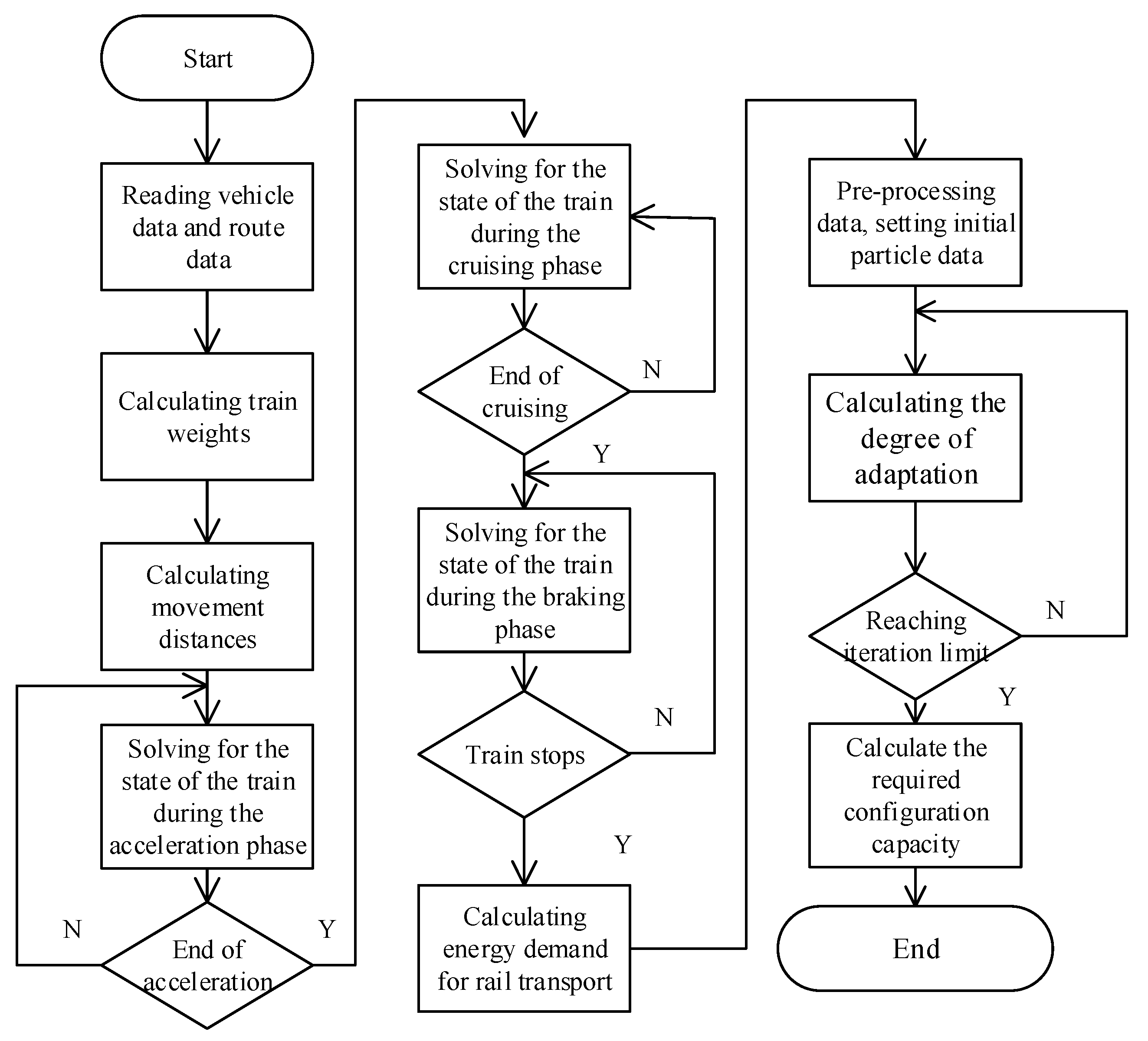
The overall optimization process of this study is shown in Figure 5.
4. Simulation Example
In order to validate the relevant methods in this paper, relevant arithmetic simulations have been set up. The simulation uses the full-load operating parameters of Nanjing Metro Line 1, which uses the METROPOLIS modular metro train provided by Alstom, and the parameters of the train are shown in Table 1.
The train is arranged in a “4 + 2” configuration, which means that two unpowered trailers and four powered trains are used in the configuration. The train has a full load of 1860 passengers and a full operating weight of 336,600 kg.
The parameters of the traction motors used in the example are shown in Table 2. The traction motors are installed only in the moving carriages of the train, with three sets installed at the front and rear of each moving carriage; a single moving carriage contains 6 traction motors and the whole train contains 24 traction motors.
The traction characteristic curve of the traction motor is shown in Figure 6, which represents the torque and power provided by the motor at different speeds of the train.
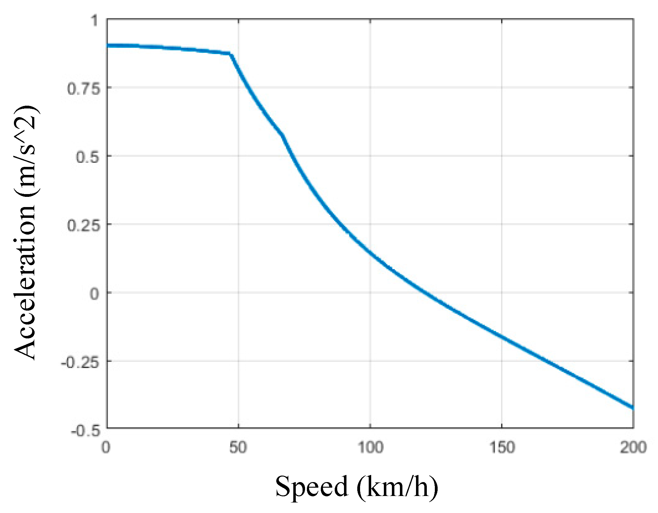
The acceleration characteristics of the train are shown in Figure 7, which represents the acceleration corresponding to different speeds and reflects the dynamical model characteristics of the train.
Table 3 shows the line and traction power supply system data used in this example. The line is five kilometers long and the traction line voltage level is 1500 V. The operation time of the train for this example is five minutes.
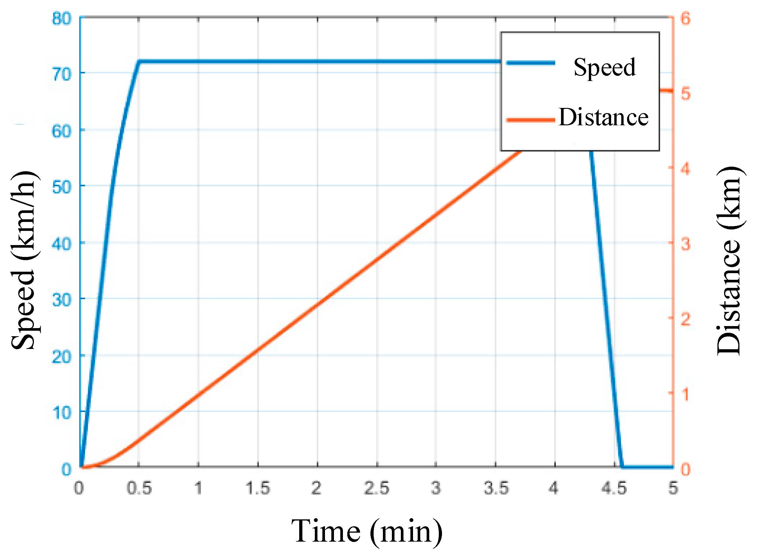
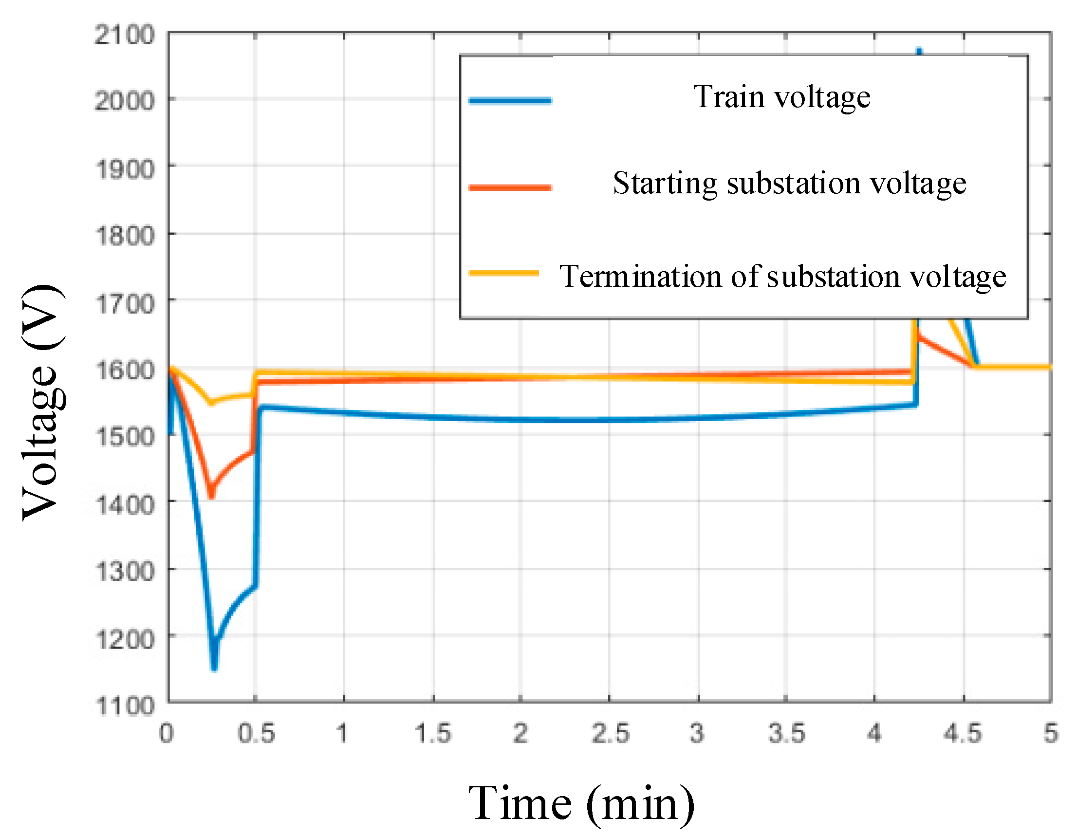
The operation state characteristics of the train are shown in Figure 8, Figure 9 and Figure 10; Figure 8 shows the relationship between the running position and speed of the train, Figure 9 shows the voltage variation of the substation and the train and Figure 10 shows the power dynamic variation characteristics of the train.
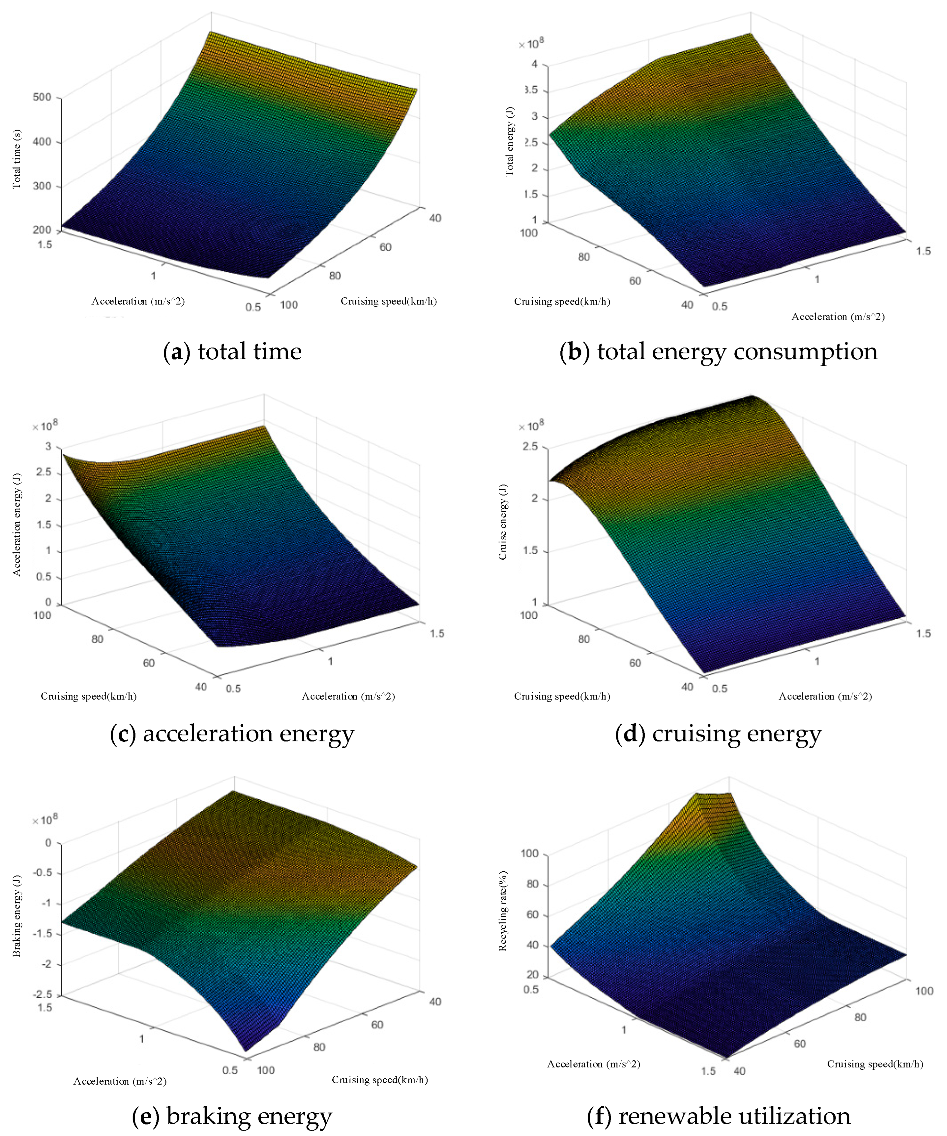
Figure 11 shows the energy consumption indicators for train operation, with the relevant variables being acceleration and cruising speed. In this figure, (a) reflects the total time, (b) reflects the total energy, (c) reflects the acceleration energy, (d) reflects the cruising energy, (e) reflects the braking energy and (f) reflects the renewable utilization.
As shown in the figure, the operating parameters of the train have an impact on the energy consumption characteristics, with higher acceleration and cruising speed reducing the corresponding running time but generating higher energy consumption and power shocks. The analysis of the regenerative utilization rate shows that when the acceleration is less than 1 m/s2 there is a high recycling rate and the design requirements for passenger comfort are met. On the other hand, the cruising speed is in the range of 70–80 km/h when the recycling rate is at its peak, and considering the energy consumption, running time and acceleration index, 72 km/h is chosen as the cruising speed for this example.
The optimization parameters for this example are shown in Table 4, which is derived from our data summary of related projects in China in recent years [12,14,15].
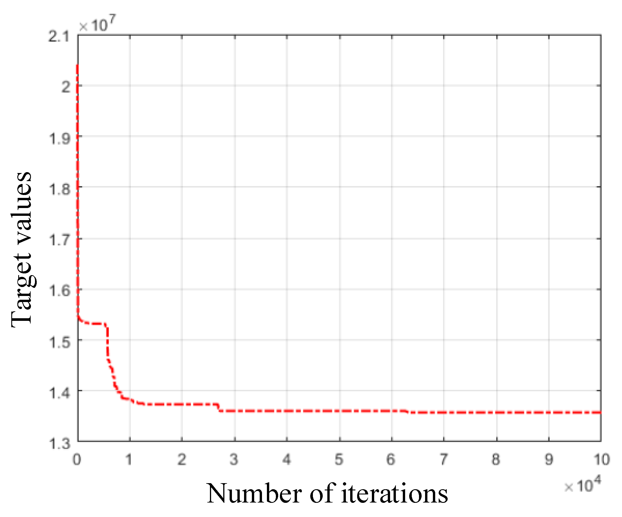
The method of solving is particle swarm optimization. The number of iterations is set to 100,000 and the particle size is 100. The trend of adaptation for this example is shown in Figure 12.
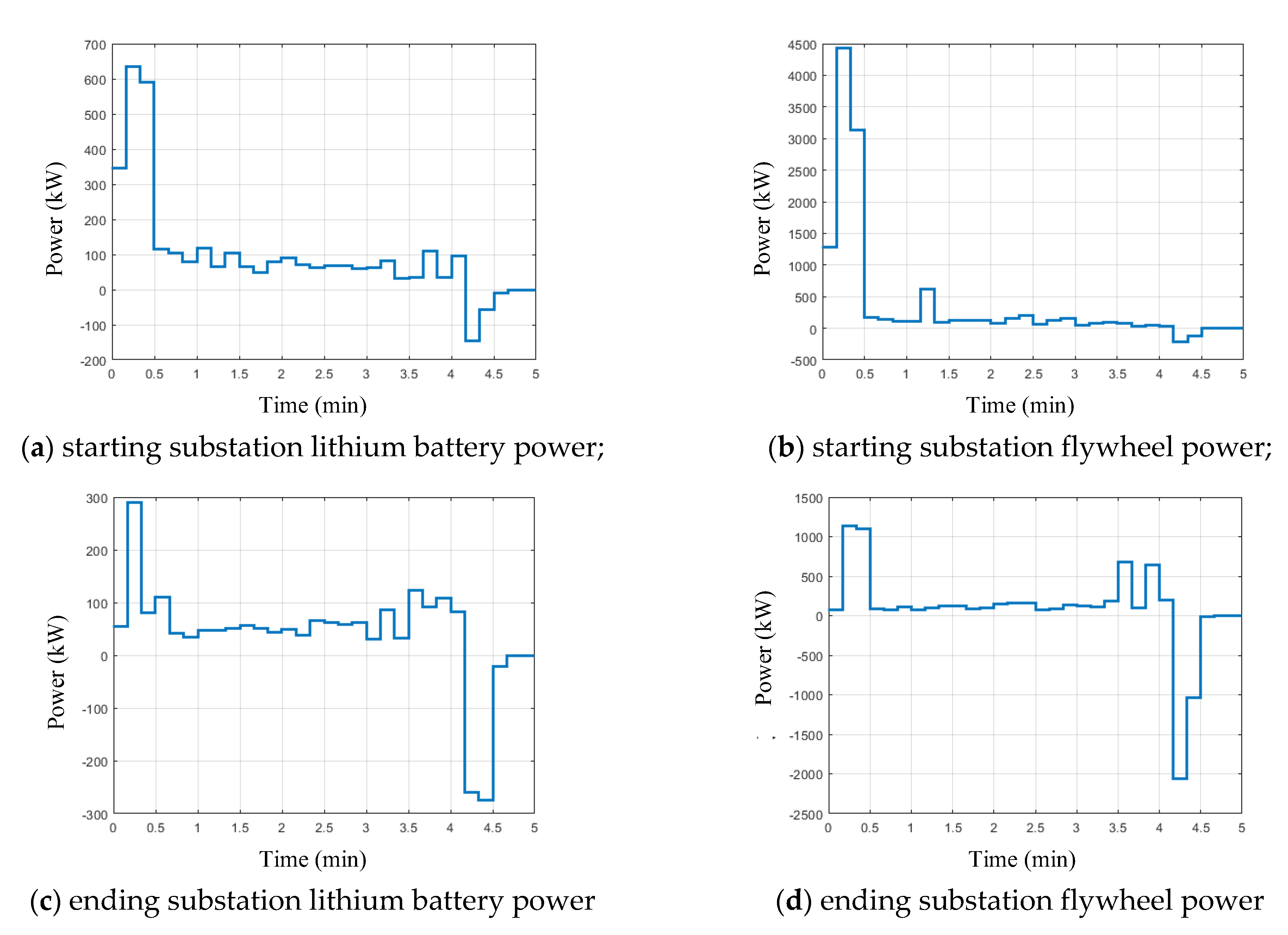
The sequence of energy storage power obtained from the search is shown in Figure 13, where (a) is the starting substation lithium battery power, (b) is the starting substation flywheel power, (c) is the ending substation lithium battery power and (d) is the ending substation flywheel power.
The calculations result in a fixed capacity of 636 kw/718 kwh of lithium battery and 4437 kw/692 kwh of flywheel energy storage for the initial substation and 290 kw/435 kwh of lithium battery and 2055 kw/395 kwh of flywheel energy storage for the terminating substation. The optimization results are shown in Table 5. The regeneration rate of the proposed scheme is 48.8%. This optimization scheme can save 244,500 kWh of electricity per year, which is equivalent to about CNY 293.2 K.
The different configuration options for this example were compared, and the results are shown in Table 6. Compared with the system configuration of only lithium battery energy storage, the proposed hybrid energy storage configuration takes advantage of the long lifetime of flywheel energy storage and greatly reduces the replacement cost of the system. At the same time, the lithium battery storage in the hybrid energy storage increases the capacity of the energy storage system and reduces the initial cost of flywheel energy storage. The proposed hybrid energy storage solution can reduce the total cost by 20% to 40%.
5. Conclusions
In this paper, a theory based on the traction process in rail transport has been studied; the study analyzes the power and energy requirements in this rail system of hybrid energy storage. A model of the electromechanical characteristics of rail traction is constructed, including a dynamics model, a traction motor model and a traction power supply system model. Based on the model, the energy demand of rail transport is solved. The economics and energy storage characteristics of the hybrid energy storage are modeled. An optimization strategy is used for the rational allocation of power and constant capacity calculations, in which a hybrid energy storage power sequence is developed that can be used as a control strategy. Finally, the rationality of the method in this paper is demonstrated by means of an arithmetic analysis. The solution can recover 48.8% of the energy and can reduce costs by 20% to 40%.
Author Contributions
Funding acquisition, S.M.; Methodology, J.L.; Project administration, C.L.; Writing—original draft, D.X. All authors have read and agreed to the published version of the manuscript.
Funding
This research was funded by Beijing Natural Science Foundation Project grant number [21JC0026] and National Natural Science Foundation of China grant number [5227071399].
Conflicts of Interest
The authors declare no conflict of interest.
References
- Chukwu, U.C.; Mahajan, S.M. Real-Time Management of Power Systems with V2G Facility for Smart-Grid Applications. IEEE Trans. Sustain. Energy 2014, 5, 558–566. [Google Scholar] [CrossRef]
- Hu, K.; Yi, P.; Liaw, C. An EV SRM Drive Powered by Battery/Supercapacitor with G2V and V2H/V2G Capabilities. IEEE Trans. Ind. Electron. 2015, 62, 4714–4727. [Google Scholar] [CrossRef]
- Liu, H.; Ning, H.; Zhang, Y.; Guizani, M. Battery Status-aware Authentication Scheme for V2G Networks in Smart Grid. IEEE Trans. Smart Grid 2013, 4, 99–110. [Google Scholar] [CrossRef]
- Zhang, W.; Gu, X.; Zhang, L. Robust Controller Considering Road Disturbances for a Vehicular Flywheel Battery System. Energies 2022, 15, 5432. [Google Scholar] [CrossRef]
- Li, H.; Chu, J.; Sun, S. High-Performance Flywheel Hybrid Powertrain. Sustainability 2022, 14, 8076. [Google Scholar] [CrossRef]
- Hu, H.; Zheng, Z.; He, Z.; Wei, B.; Wang, K.; Yang, X.; Wei, W. Transportation energy Internet architecture and key technologies. Chin. J. Electr. Eng. 2018, 38, 12–24+339. [Google Scholar]
- Luo, A.; Wu, C.; Shen, J.; Shuai, Z.; Ma, F. Railway Static Power Conditioners for High-speed Train Traction Power Supply Systems Using Three-phase V/V Transformers. IEEE Trans. Power Electron. 2011, 26, 2844–2856. [Google Scholar] [CrossRef]
- He, X.; Shu, Z.; Peng, X.; Zhou, Q.; Zhou, Y.; Zhou, Q.; Gao, S. Advanced Cophase Traction Power Supply System Based on Three-Phase to Single-Phase Converter. IEEE Trans. Power Electron. 2014, 29, 5323–5333. [Google Scholar] [CrossRef]
- Zhang, D.; Zhang, Z.; Wang, W.; Yang, Y. Negative Sequence Current Optimizing Control Based on Railway Static Power Conditioner in V/v Traction Power Supply System. IEEE Trans. Power Electron. 2016, 31, 200–212. [Google Scholar] [CrossRef]
- Deng, W.; Dai, C.; Han, C.; Bai, X.; Chen, W. Railway back-to-back hybrid energy storage system considering regenerative braking energy recovery and power quality improvement and its control method. Chin. J. Electr. Eng. 2019, 39, 2914–2924. [Google Scholar]
- Wei, W.; Hu, H.; Wang, K.; Chen, J.; He, Z. Energy storage scheme and control strategy of high-speed railway traction power supply system based on railway power regulator. J. Electrotech. 2019, 34, 1290–1299. [Google Scholar] [CrossRef]
- Li, Q.; Wang, X.; Huang, X.; Zhao, Y.; Liu, Y.; Zhao, S. Research on flywheel energy storage technology of electrified railway. Chin. J. Electr. Eng. 2019, 39, 2025–2033. [Google Scholar] [CrossRef]
- Feng, Y.; Chen, S.; Ran, X.; Bai, Y.; Jia, W. Study on energy-saving operation optimization method of urban rail transit train considering the utilization of regenerative braking energy. J. Railw. 2018, 40, 15–22. [Google Scholar]
- Hu, H.; Chen, J.; Ge, Y.; Huang, W.; Liu, L.; He, Z. Research on regenerative braking energy storage and utilization technology for high-speed railroads. Chin. J. Electr. Eng. 2020, 40, 246–256+391. [Google Scholar]
- Deng, W.-L.; Dai, Z.-H.; Chen, W.-R. Application of photovoltaic in AC/DC traction power supply system in the context of rail transportation energy internet and analysis of key issues. Chin. J. Electr. Eng. 2019, 39, 5692–5702+5897. [Google Scholar]
Figure 1.
Stress model of rail transit.

Figure 2.
Motor traction characteristic model.

Figure 3.
Traction power grid model.

Figure 4.
Rail transit operation characteristic model.

Figure 5.
Optimization strategy solving process.

Figure 6.
Electromechanical characteristics of traction motor.

Figure 7.
Acceleration characteristics of traction motor.

Figure 8.
Relationship between train operation position and speed.

Figure 9.
Voltage variation diagram of substation and train.

Figure 10.
Dynamic change characteristics of train power.

Figure 11.
Energy consumption index of train operation.

Figure 12.
Fitness change trend.

Figure 13.
Energy storage power sequence.


Table 1.
Train simulation parameters.
| Parameter | Value |
|---|---|
| Weight of trailer | 34,900 kg |
| Weight of moving trains | 38,800 kg |
| Number of trailers | 2 |
| Number of moving vehicles | 4 |
| Full capacity of trailers | 302 |
| Full capacity of moving trains | 314 |
| Number of wheels for moving vehicles | 6 |
| Basic resistance factor | 2.4 |
| Mechanical resistance factor | 0.014 |
| Pneumatic resistance factor | 0.001293 |
| Slewing factor | 0.12 |
Table 2.
Parameters of traction motor.
| Parameter | Value |
|---|---|
| Maximum traction power | 286 kW |
| Maximum braking power | 386 kW |
| Maximum torque | 1000 N·m |
| polar logarithm | 3 |
| Rated voltage | 675 V |
| Motor efficiency | 91% |
| Converter efficiency | 97% |
| Transmission ratio | 6.95 |
| Wheel radius | 0.4025 m |
| Transfer rate resistance ratio | 150.9 |
Table 3.
Parameters of line and traction power grid.
| Parameter | Value |
|---|---|
| Line length | 5 km |
| Cruising speed | 72 km/h |
| Acceleration limit value | 1.5 m/s2 |
| Unit transmission line resistance | 2.5 × 10⁻⁵ Ω |
| Unit rail resistance | 4.0 × 10⁻⁵ Ω |
| Substation no-load voltage | 1600 V |
| Substation equivalent internal resistance | 0.054 Ω |
Table 4.
Constant volume optimization data.
| Parameter | Value |
|---|---|
| Year of project | 15 years |
| Discount rate | 6% |
| Lithium battery cost per unit capacity | 4500 CNY/kW |
| Lithium battery cost per unit of power | 9000 CNY/kW |
| Life span of lithium batteries | 6 years |
| Minimum charge/discharge multiplier for lithium batteries | 0.2 |
| Maximum charge/discharge multiplier for lithium batteries | 1 |
| Flywheel unit capacity cost | 100,000 CNY/kW |
| Flywheel cost per unit of power | 1000 CNY/kW |
| Flywheel service life | 15 years |
| Minimum charge/discharge multiplier for flywheels | 2 |
| Maximum charge/discharge multiplier for flywheels | 10 |
| Number of operating investment contacts | 0.02 |
Table 5.
Optimization results.
| Parameter | Result before Optimization | Result after Optimization |
|---|---|---|
| Starting substation Power purchase | 53.05 kW·h | 53.40 kW·h |
| Ending substation Power purchase | 35.89 kW·h | 25.86 kW·h |
| Total purchased power | 88.94 kW·h | 79.26 kW·h |
Table 6.
Optimization results.
| System Configuration | Installation Cost | Replacement Cost | Operating Cost | Total Cost |
|---|---|---|---|---|
| Hybrid energy storage | CNY 1361.5 K | CNY 171.6 K | CNY 272.3 K | CNY 1805.4 K |
| Only lithium battery energy storage | CNY 794.3 K | CNY 1374.8 K | CNY 158.8 K | CNY 2327.9 K |
| Only flywheel energy storage | CNY 2454.0 K | / | CNY 490.8 K | CNY 2944.7 K |
Publisher’s Note: MDPI stays neutral with regard to jurisdictional claims in published maps and institutional affiliations. |
© 2022 by the authors. Licensee MDPI, Basel, Switzerland. This article is an open access article distributed under the terms and conditions of the Creative Commons Attribution (CC BY) license (https://creativecommons.org/licenses/by/4.0/).
Share and Cite
MDPI and ACS Style
Xin, D.; Li, J.; Ma, S.; Liu, C. Research on Demand Analysis and Optimal Allocation of Rail Transit Hybrid Energy Storage Based on the Electric Traction Model. Energies 2022, 15, 6970. https://0-doi-org.brum.beds.ac.uk/10.3390/en15196970
AMA Style
Xin D, Li J, Ma S, Liu C. Research on Demand Analysis and Optimal Allocation of Rail Transit Hybrid Energy Storage Based on the Electric Traction Model. Energies. 2022; 15(19):6970. https://0-doi-org.brum.beds.ac.uk/10.3390/en15196970
Chicago/Turabian StyleXin, Dixi, Jianlin Li, Suliang Ma, and Chang’an Liu. 2022. "Research on Demand Analysis and Optimal Allocation of Rail Transit Hybrid Energy Storage Based on the Electric Traction Model" Energies 15, no. 19: 6970. https://0-doi-org.brum.beds.ac.uk/10.3390/en15196970
Note that from the first issue of 2016, this journal uses article numbers instead of page numbers. See further details here.