Article

Full-Core Coupled Neutronic, Thermal-Hydraulic, and Thermo-Mechanical Analysis of Low-Enriched Uranium Nuclear Thermal Propulsion Reactors

Georgia Institute of Technology, George W. Woodruff School, Nuclear and Radiological Engineering, Atlanta, GA 30313, USA
*
Author to whom correspondence should be addressed.
Submission received: 31 August 2022 / Revised: 20 September 2022 / Accepted: 20 September 2022 / Published: 24 September 2022
(This article belongs to the Special Issue State-of-Art in Nuclear Reactor Physics)

Abstract

:
Nuclear thermal propulsion is an enabling technology for future space missions, such as crew-operated Mars missions. Nuclear thermal propulsion technology provides a performance benefit over chemical propulsion systems by operating with light propellants (e.g., hydrogen) at elevated engine chamber conditions. Therefore, nuclear thermal propulsion reactor cores exhibit high propellant velocities and elevated propellant and fuel temperatures, subsequently leading to relatively high thermal stresses and geometrical deformation. This paper details the numerical approach to solve the thermo-elastic equations, which was implemented into the recently developed ntpThermo code. In addition, this paper demonstrates the extension of the Basilisk multiphysics framework to perform full-core coupled neutronic, thermal-hydraulic, and thermo-mechanical analysis of nuclear thermal propulsion reactors. The analyses demonstrate and quantify thermo-mechanical feedback, which for the investigated cases, acted to reduce maximum fuel temperatures and pressure drop across the fuel element channels. Thermo-mechanical feedback had a significant impact on the mass flow distribution within the reactor core and, thus, a substantial impact on solid-material temperatures and stresses, but only a minor impact on reactivity and local power distributions. Sensitivity studies revealed that the friction factor correlation applied to perform the analysis has a significant impact on the pressure drop across the fuel element channels. The most important observation of this research is the importance of incorporating the thermo-mechanical feedback within an integrated multiphysics solution sequence to enable the consistent design of future nuclear thermal propulsion systems.

1. Introduction

Nuclear thermal propulsion (NTP) systems are a candidate technology for crew-operated Mars missions by the National Aerospace and Space Administration (NASA) and Cis-Lunar operations by the Defense Advanced Research Projects Agency (DARPA). NTP engines use the energy generated by fission to heat the working fluid, typically hydrogen, to achieve extremely high temperatures (~2700 K) and considerable chamber pressures (~7 MPa). This allows NTP engines to produce twice the specific impulse (Isp) of an ideal chemical rocket engine while also providing thrust levels on the order of 10,000 pounds (lbf). NASA is currently advancing state of the art low-enriched uranium (LEU) NTP designs with the objective of using NTP engines for human Mars missions in 2039 [1,2,3]. Recently, DARPA announced that the Demonstration Rocket for Agile Cislunar Operations (DRACO) program is targeting a 2026 integrated engine in-space flight demonstration mission to mature NTP technology for near-term applications [4]. Modern LEU designs for Mars transit target thrust values in the range of 12,500–25,000 lbf with an Isp of 900 s [1]. In order to achieve an Isp of 900 s, the average exit bulk coolant temperature must be at least 2700 degrees kelvin, which implies even greater fuel temperatures (~2900 K). An additional important performance requirement is a high thrust-to-weight ratio (≥1.8). Satisfying both the Isp and thrust-to-weight ratio requirements leads to an extremely high power-density (≥1 MW/L) reactor design, thus, presenting a significant design challenge. Multiphysics modeling and simulation (M&S) tools capable of capturing the relevant feedback mechanisms are required to drive the development of a reactor design that satisfies engine performance requirements while maintaining adequate thermal and mechanical safety margins.
The need to develop advanced M&S capabilities for the design of NTP reactors has been highlighted by a recent National Academy of Science, Engineering, and Medicine (NASEM) study [5], which recommended that “NASA should rely on extensive investments in modeling and simulation”, in addition to ground testing and cargo missions to qualify NTP systems for crewed missions. Recent research [3,6] has demonstrated that a multiphysics solution approach is required for the design and analysis of NTP systems; however, the significance of various feedback mechanisms within the multiphysics solution approach is not well quantified. Typically, neutronics is coupled with thermal-hydraulics (T/H) to account for the impact of variations in solid-material temperatures and coolant density on reactivity and power distributions. Currently, sparse literature exists on the importance of including other feedback mechanisms, such as thermo-mechanics (T/M), within a multiphysics solution scheme to analyze LEU NTP reactors. Previous research has leveraged higher-order codes to perform T/H and T/M analysis of a single supercell [7,8]. However, the previously mentioned analyses have not considered the impact of T/M feedback on the T/H solution. Several papers have recommended the inclusion of T/M feedback within a multiphysics solution approach [3,9]. This recommendation was substantiated by recent research, which demonstrated that T/M feedback impacts the mass-flow distribution and, thus, solid-fuel temperatures of multichannel simulations of an NTP fuel element (FE) [10].
This paper details the T/M solution approach implemented into the ntpThermo code [11] and the implementation of a coupled neutronic, T/H, T/M (N+T/H-T/M) solution sequence into the Basilisk multiphysics framework [6]. The primary objective of this paper is to demonstrate the importance of T/M feedback in coupled N+T/H-T/M simulations. The results presented here demonstrate that the coupled T/M feedback reduces maximum fuel temperatures, pressure drops across the FE channels, and increases maximum von Mises (VM) stresses within the FE channels. The thermal expansion of coolant channels significantly impacts the pressure losses and heat transfer characteristics within the FE channels and, thus, the mass flow and fuel temperature distributions within the core. Neglecting the T/M feedback can lead to inconsistencies in the fuel temperature and VM stress spatial distributions, which are important for systematic design studies. The sensitivity studies performed in this paper reveal that the pressure drop across the FE channels is dependent on the friction factor correlation applied to solve the problem. To conclude, this paper demonstrates the importance of T/M feedback within a multiphysics solution approach in predicting consistent safety margins.

2. Codes and Methods

Section 2.1 contains a brief overview of the ntpThermo code. Section 2.2 contains a description of the thermoelastic equations solution approach. Finally, Section 2.3 describes the iterative T/H-T/M solution scheme and the N+T/H-T/M solution sequence.

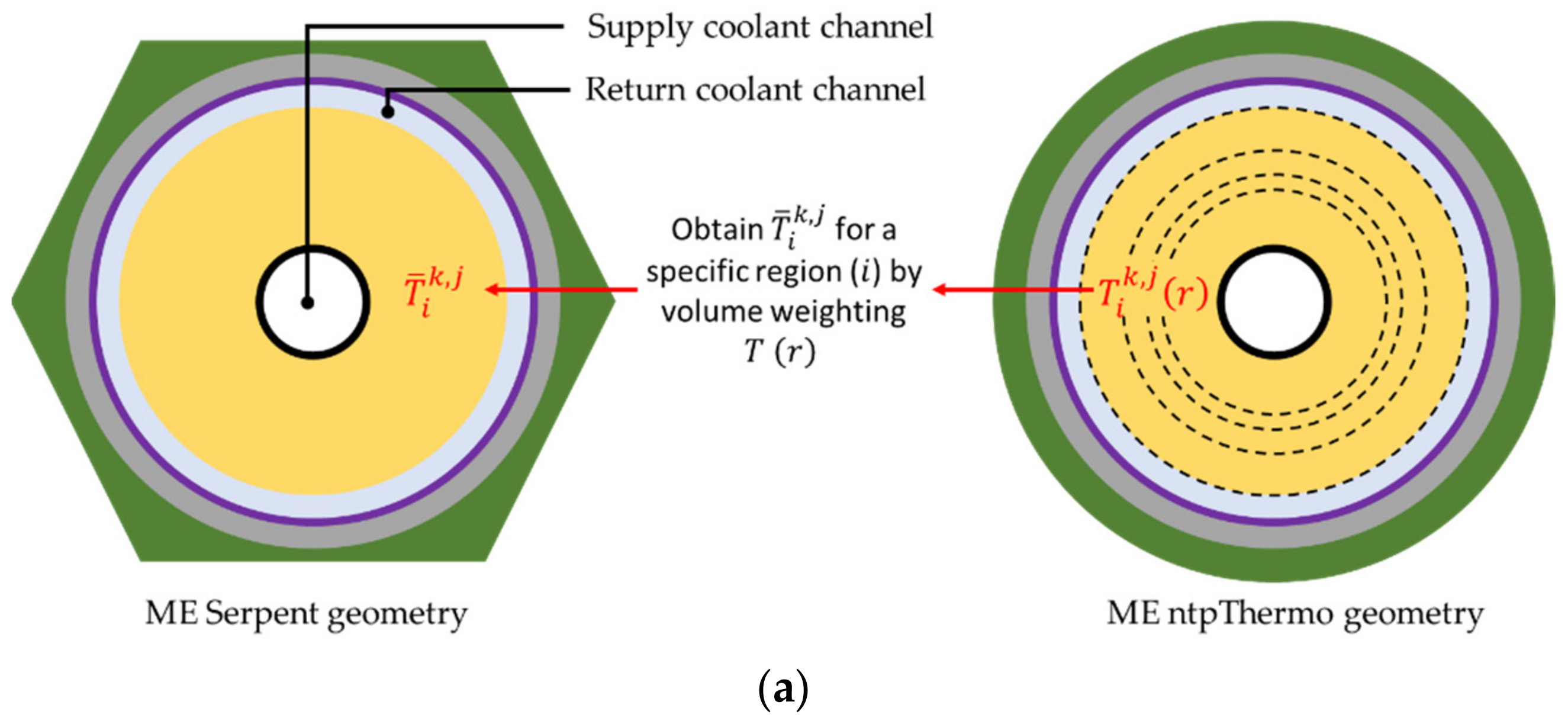
2.1. Overview of the ntpThermo Code

The ntpThermo code was developed to fill the gap between expensive high-order computational fluid dynamics (CFD) codes and unvalidated reduced-order codes for the analysis of NTP reactors. Higher-order codes are non-ideal for full-core multiphysics analysis due to their computational cost. While ntpThermo is not intended to replace higher-order codes, it is an ideal code for a coupled full-core N+T/H analysis because of reduced computational cost and adequate accuracy [11]. The code relies on an equivalent model with a 1.5 D conduction–convection solution. A numerical solution scheme was implemented to solve each axial layer with the convective solution relying on Newton’s law of cooling. An iterative solution scheme was developed to solve the counterflow within the moderator element (ME) and capture the heat conducted from the fuel to the moderator for various supercell configurations. This numerical solution scheme was verified against a series of higher-order OpenFOAM CFD benchmarks [11]. The code contains a mass flow convergence scheme that balances the mass flow rate to achieve an equal pressure drop in each channel, where the user provides the inlet pressure of each channel [6]. In this work, each channel is assumed to have the same inlet pressure obtained from the engine cycle analysis summarized in Section 3.1. This solution scheme was applied to converge the mass flow distribution within the FEs and MEs for the analysis detailed in Section 4. Additionally, a comprehensive material properties interface was developed to accommodate temperature and pressure-dependent coolant thermophysical properties as well as user-defined two variable-dependent solid-material properties.

2.2. Thermoelastic Equations Solution Methodology

The T/M solver implemented in ntpThermo leverages the approach developed by Peng and Li [12], where the thermoelastic problem is cast as a second-order Fredholm integral equation. The primary advantage of this approach is the ability to capture temperature-dependent properties in the solution of the thermoelastic equations. This capability is necessary to model an NTP system as the power densities inherent in NTP systems induce significant temperature gradients within the fuel. Additionally, the thermophysical properties of the fuel and cladding materials are a strong function of temperature.
The solution method assumes an axisymmetric plane stress problem where the axial stress ( σ z ) and strain ( ε z ) are assumed to be zero, which is consistent with previous industry studies [1,13]. On the basis of this assumption, the equations for the radial ( σ r ) and tangential ( σ θ ) stresses can be detailed by Equations (1) and (2), respectively. The radial ( ε r ) and hoop strain ( ε θ ) are detailed by Equations (3) and (4), respectively.
σ r r = Ε r 1 v r 2 ε r + v r ε θ α r 1 + v r T r
σ θ r = Ε r 1 v r 2 ε θ + v r ε r α r 1 + v r T r
ε r = d u r d r
ε θ = u r r
where E is Young’s modulus, v is Poisson’s ratio, and α is the coefficient of thermal expansion, which are all spatially dependent. It is important to note that T r is the difference between the absolute temperature ( T a b s ) obtained by the thermal solver and the reference temperature zero stress temperature ( T r e f α ); this relationship is detailed in Equation (5).
T r = T a b s r T r e f α
On the basis of the equations detailed above, the radial displacement ( u r ) and tangential stress ( σ θ ) can be represented by Equations (6) and (7), respectively. The equivalent von Mises stress ( σ V M ) is calculated via Equation (8).
u r r = A χ r + 1 χ r a r χ r 1 v s 2 Ε s σ r s + α s 1 + v s T s d s
σ θ r = v r σ r r + E r u r r r E r α r T r
σ V M = σ r 2 σ r σ θ + σ θ 2
where A in Equation (6) is a constant to be determined through appropriate boundary conditions, and χ r can be calculated via Equation (9).
χ r = exp a r v s s d s
When Equations (3) and (4) are substituted into the equilibrium equation, Equation (10) is produced.
d σ r d r + σ r σ θ r = 0
Substituting Equation (6) into Equation (7) and then into Equation (10) yields Equation (11)
d σ r d r + 1 v r r σ r E r r 2 χ r a r 1 v 2 ρ χ ρ Ε ρ σ r ρ d ρ = F r + A E r r 2 χ r
where a is the inner radius of the equivalent annulus, and F r is:
F r = E r r 2 χ r a r χ ρ α ρ 1 + v ρ T ρ d ρ E r α r T r r
Integrating Equation (11) with respect to r yields Equation (13)
σ r r + a r K r , ρ σ r ρ d ρ = F 1 r + A f r + B K r , ρ = 1 v ρ v ρ 1 v 2 ρ χ ρ E ρ   ρ r E s s 2 χ s d s F 1 r = a r F ρ d ρ f r = a r E s s 2 χ s d s
The constants A and B can be found via Equations (14) and (15), respectively, where σ r a is the radial stress at the inner radius of the equivalent annulus and σ r b is the radial stress at the outer radius of the equivalent annulus.
A = σ r b σ r a f b F 1 b f b + 1 f b a b K b , ρ σ r ρ d ρ
B = σ r a
Now we insert the constants A and B back into the integrodifferential equation for the radial stress to obtain Equation (16) which has the form of a second-order Fredholm integral equation.
σ r = a b L r , ρ σ r ρ d ρ = h r
The kernel function L r , ρ is detailed in Equation (17) and h r is detailed in Equation (18).
L r , ρ = K r , ρ f r f b K b , ρ ρ < r f r f b K b , ρ ρ > r
h r = F 1 r + f r f b σ r a + σ r b F 1 b + σ r a
The T/M solution is obtained using the finite element data provided by the T/H heat transfer solution. More specifically, the finite element solid-material temperatures are used to obtain the temperature-dependent mechanical properties (e.g., α ). These finite element temperatures, properties, and radial dimensions are then used to solve the different integrals appearing in Equations (6)–(18) via numerical integration. The latter enables the calculation of stresses and thermal expansion in each finite element radial region. This can be used to update the finite element mesh within an iterative T/H-T/M solution sequence. The described solution relies only on a 1 dim radial approach, also referred to as the equivalent annulus approximation. A detailed description of radial and axial discretization of the mesh can be found in previous research [11,14]. The numerical solution technique implemented in ntpThermo leverages the previously developed and verified approach by Atkinson and Shampine [15]. The algorithm provides a numerical solution for integral equations in the form:
λ x s a b K s , t x t d t = f s a s b
which can be written symbolically as:
λ K x = f
The routine implemented solves integral equations with kernel functions K s , t that are relatively smooth on R = a , b × a , b for the interval a , b . The procedure relies on Simpson’s rule to discretize the equation to get an approximate solution on all of a , b . The solution begins by approximating the integral operator using a quadrature scheme:
a b g t d t j = 0 n w j , n g t j , n
For smooth kernels, the composite Simpson’s rule for irregularly uneven spaced data with an even number of subintervals, each with a subinterval thickness of h , is detailed in Equation (22).
a b f t d t = h 3 f x 0 + 2 j = 1 N / 2 1 f x 2 j + 4 j = 1 N / 2 f x 2 j 1 + f x n
It must be noted that the current implementation is limited to only cases where the radial mesh is divided into an even number of regions. However, the individual thickness of each subregion may be different. Simpson’s rule is then used to generate the weight coefficients ( w j , n ) such that λ K x = f can be approximated by Equation (23). Combing the relations detailed above leads to a linear system of equations that can be solved via Equation (24), which is ultimately used to obtain σ r r . The numerical implementation within ntpThermo has been previously verified against analytical benchmarks [16].
λ x n s j = 0 n w j , n K s , t j , n x t j , n = f s
x n s = 1 λ f s + j = 0 n w j , n K s , t j , n x t j , n

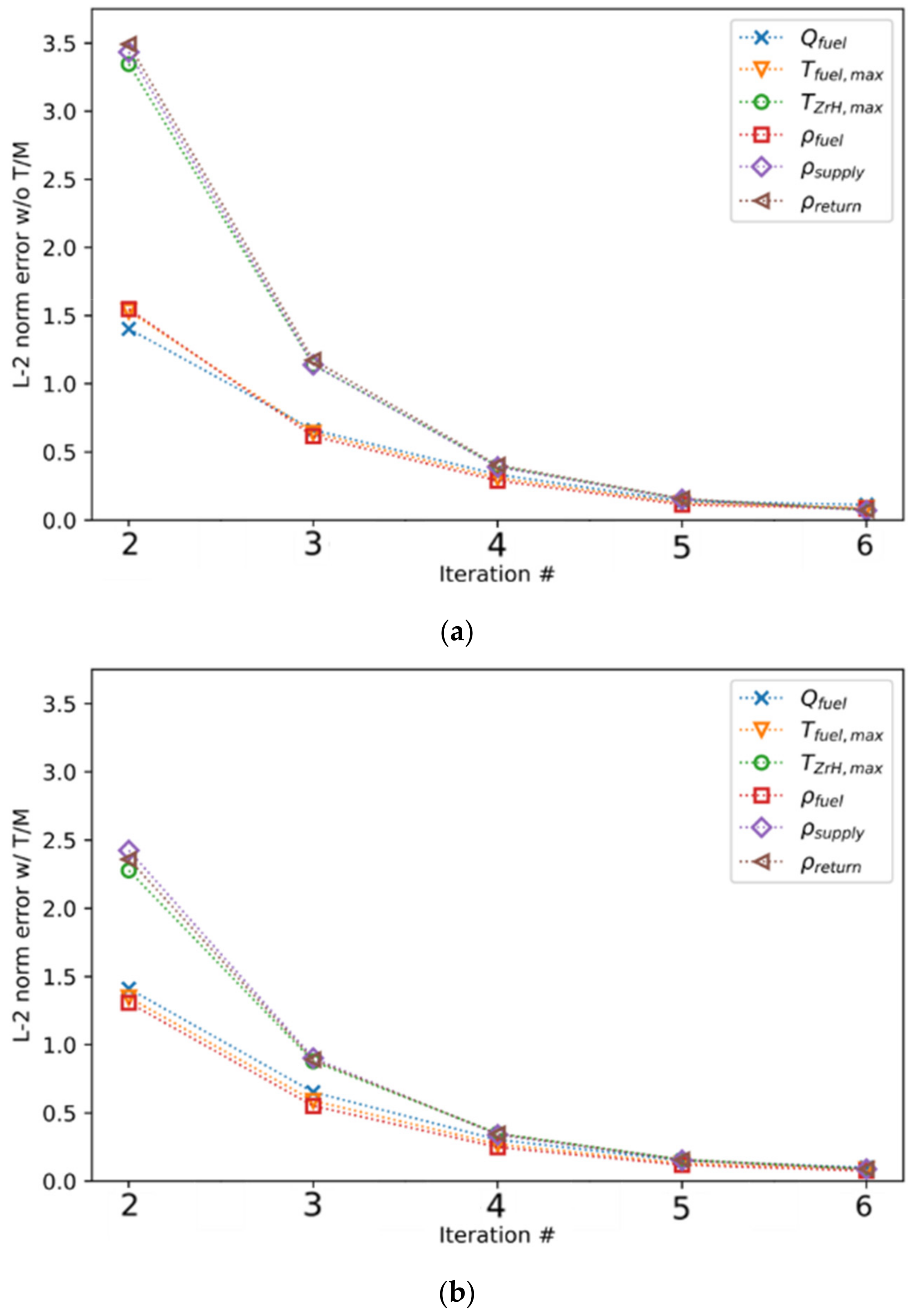
2.3. Coupled Neutronic, Thermal-Hydraulic, Thermo-Mechanical Solution Sequence

The T/M solution utilizes equivalent annulus approximation and, therefore, the same radial and axial mesh as the T/H solution. The temperature distributions obtained from the T/H solution can be directly used by the T/M solver in conjunction with temperature-dependent mechanical properties. The coupled T/H-T/M solution sequence, detailed in Figure 1, begins by iteratively solving the multichannel T/H problem to obtain a converged mass flow rate distribution m ˙ . The multichannel T/H solution temperature distribution, dimensions, and temperature-dependent mechanical properties are then input to the T/M solver. The T/M solver returns the radial stress and thermal expansion distributions for each axial layer of each coolant channel specified in the problem. The T/M solution is used to update the radial mesh of each axial layer of each channel, including the node volumes, power densities, and fluid flow areas. The updated geometry is then used by the next T/H solution iteration, where the iteration number is represented by n, to reconverge the mass flow distribution. The outlet pressure is chosen as the convergence criteria for the coupled T/M-T/H sequence, as the T/M feedback primarily affects the pressure drop of each channel.
The coupling framework within the Basilisk code [6] was extended to account for T/M feedback applied to full-core N+T/H-T/M simulations; the solution sequence is detailed in Figure 2. The Serpent code [17] is used as the neutronic solver within the Basilisk code. The methodology for coupled N+T/H simulations has been detailed in previous research [6]. The T/M feedback is accounted for in the coupled N+T/H-T/M simulation via the impact of thermal expansion on the T/H solution; however, the dimensions in the Serpent model are not updated. The coupled sequence utilizes the Serpent multiphysics interface [18] to update the solid-material temperatures and coolant gas densities for each FE and ME in the reactor core throughout each iteration. The coupled analysis sequence converges on keff and the fuel power distribution [6]. The excess reactivity ε k e f f and fuel power distribution convergence criteria were set at 10 pcm and 1E-5, respectively, for the analysis in this paper.
The energy deposition in the active core is tallied as a function of axial height on an element-by-element basis where each FE and ME is individually tracked. Additionally, each material region within each element is uniquely tallied. However, the energy deposition within that region is assumed to be uniform (i.e., intra-element power peaking is not accounted for); however, future research may expand the T/H-T/M solution methodology to account for the intra-element power distribution within the FEs. The T/H fields are mapped to the neutronic model via the approach presented in Figure 3, where each color represents a unique material region within the ME and FE. The ntpThermo code relies on the equivalent annulus approximation and numerical conduction–convection solver [11]. As such, the volume average of the radial temperature profile obtained from the ntpThermo model of material region i for axial layer j of element k ( T ¯ i k , j ) is applied to the respective region in the neutronic model. Additionally, the bulk coolant densities in each coolant channel for every axial layer are updated.
As previously stated, the Serpent model mesh was not modified during the N+T/H-T/M solution sequence as its impact is relatively small. A two-dimensional x-y Serpent model was used to investigate the impact of explicitly modeling the thermal expansion of FE coolant channels. The T/H fields at the core mid-plane (z = 60 cm) obtained from the full-core N+T/H-T/M analysis in Section 4.1 were used in the analysis. This specific axial height was chosen because of the elevated fuel temperatures. Two models were constructed; the first explicitly modeled the thermal expansion of each FE within the core. The total fuel mass was preserved in the expanded model by modifying each fuel material’s density. The second model did not account for any thermal expansion (i.e., all the coolant channels are identical). Only a 23 pcm difference in reactivity was observed between the two models, where the statistical uncertainty was 13 pcm. The observed RMS error between the two radial power distributions was 0.04%, where the average statistical uncertainty in each power detector was 0.11%. This analysis demonstrates that the explicit modeling of coolant channel thermal expansion has a negligible impact on reactivity and local power distributions.

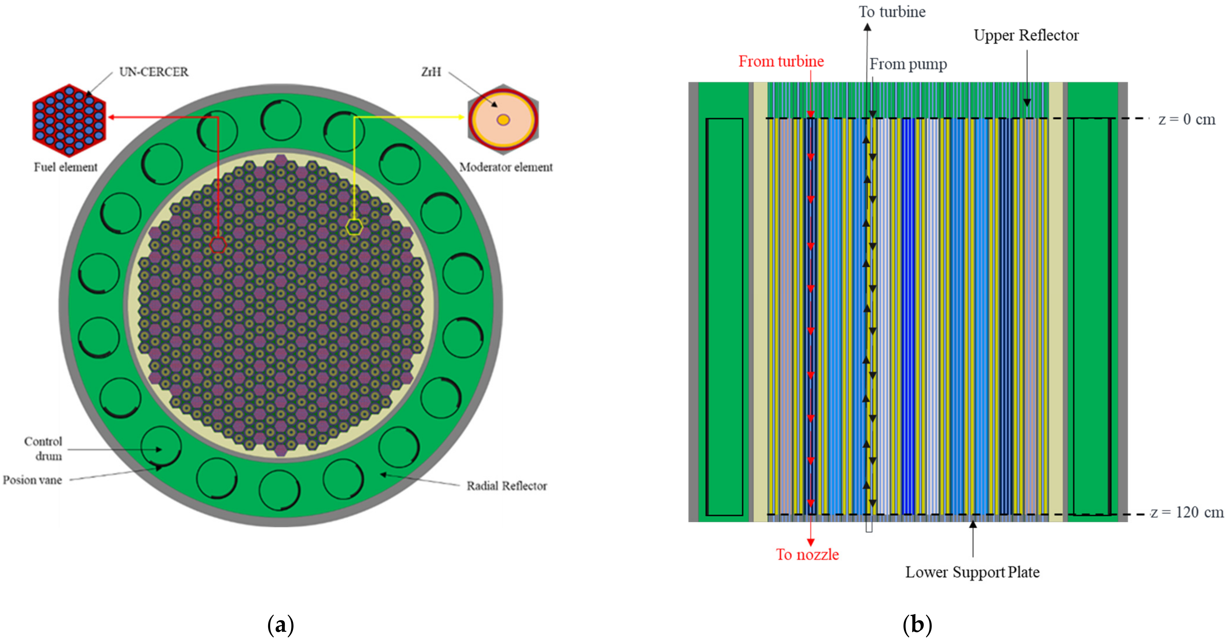
3. Reactor Design Description

Section 3.1 contains a description of the reactor design considered. Section 3.2 contains a brief description of the temperature-dependent mechanical material properties used in the T/M solution of the FEs.

3.1. Reactor Design Description

The reactor design considered in this paper is a Nuclear Engine for Rocket Vehicle Applications (NERVA) derived design, where the active core region is composed of hexagonal internally cooled FEs and dual-pass tie-tube MEs. The geometry of the fuel and MEs is identical to those previously studied, and several key parameters are detailed in Table 1 [6]. The radial and axial core cross-sections are detailed in Figure 4. A detailed design description of the reactor configuration and engine expander cycle can be found in previous research [14,19]. The design uses a Ceramic–Ceramic (CERCER) fuel form, where Zirconium Carbide (ZrC) coated High Assay Low-Enriched Uranium (HALEU) Uranium Nitride (UN) fuel kernels are embedded in a ZrC matrix [1]. This fuel form is currently favored over previously investigated Ceramic–Metallic (CERMET) fuel forms because of its reduced weight and parasitic neutron absorption. The moderator material within the ME is Zirconium Hydride (ZrH1.89), which is consistent with previous industry studies [1]. An inverse pewee lattice configuration was chosen to ensure that the active core has a similar Hydrogen-to-Uranium-235 atom ratio (H:235U) as the baseline industry design [1]. The previous calculated steady-state boundary conditions [6] obtained from the NTP-Transient code [19] are applied in this paper.
The previously considered active core lattice pattern [6] was slightly modified to eliminate 26 kg of mass from the reactor subsystem and reduce the required HALEU mass by 11.1 kg while preserving a hot full-power critical drum position of 60 degrees. The Basilisk code contains a fuel loading search algorithm that adjusts the fuel volume loading of each FE to flatten the radial power distribution for a given reactor design [20]. The final fuel loading pattern detailed in Figure 5 contains only 16 unique fuel loadings, and the maximum fuel particle volume loading is 38.9 vol% particles, which is well below the recommended maximum limit of 65 vol% particles [1]. Flattening the radial power profile is necessary to minimize peak fuel temperatures and maximize the overall performance of the engine [20].

3.2. Temperature-Dependent Mechanical Material Properties

A literature review was conducted to obtain the temperature-dependent mechanical properties required to solve the thermoelastic equations. Temperature-dependent correlations for each material are detailed in Table 2. The thermophysical properties detailed in previous research were used in the T/H solution [6]. The zero-stress reference temperature was assumed to be 1500 K to remain consistent with previous studies [7]. The effective CERCER mechanical properties were obtained using the method of mixtures approach [7].

4. Coupled Multiphysics Results

This section presents the coupled N+T/H–T/M analysis. Section 4.1 demonstrates the importance of T/M feedback on full-core N+T/H–T/M analysis. Section 4.2 contains a sensitivity study that explores the impact of various friction factor correlations on the coupled N+T/H–T/M solution.

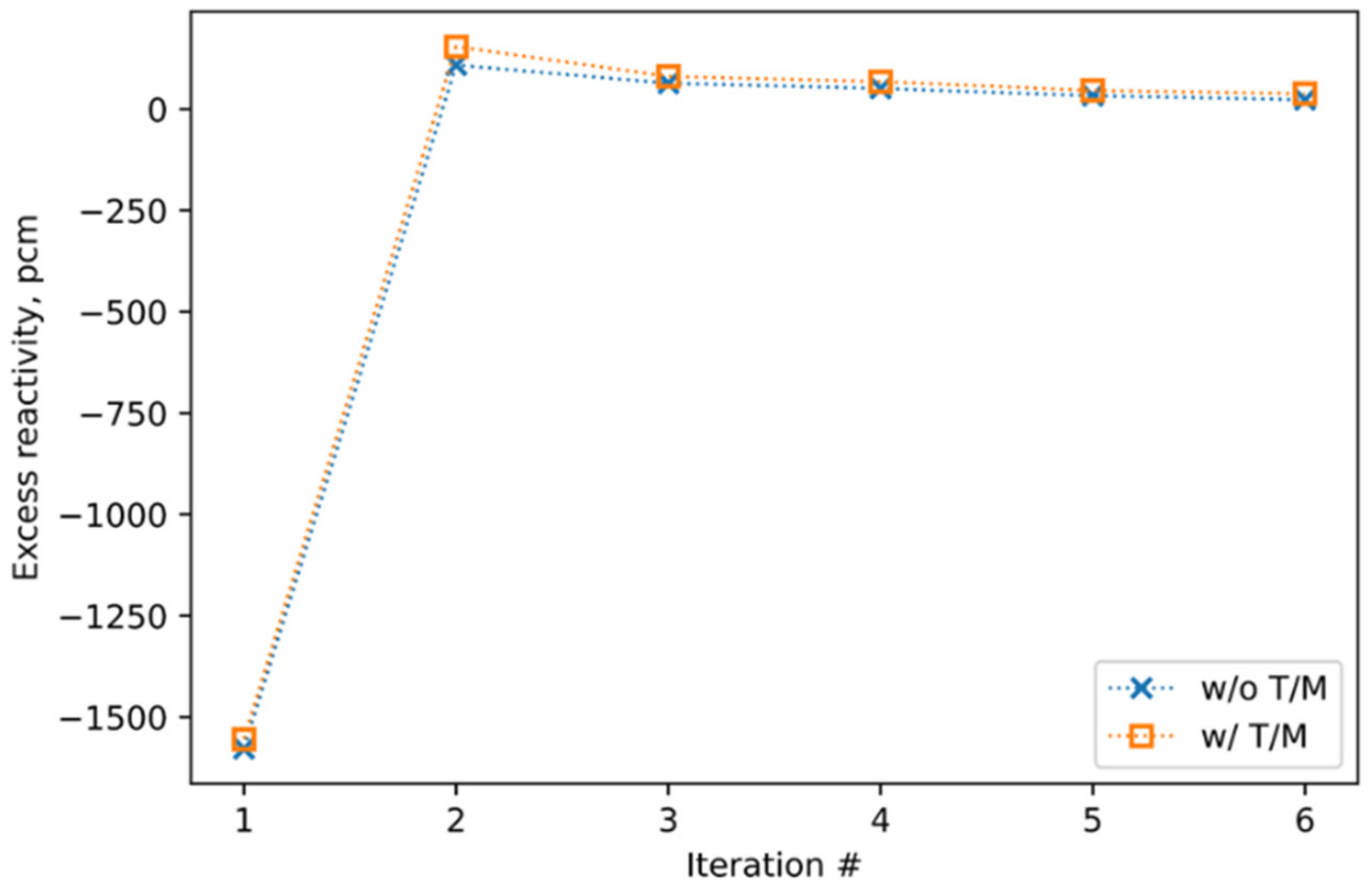
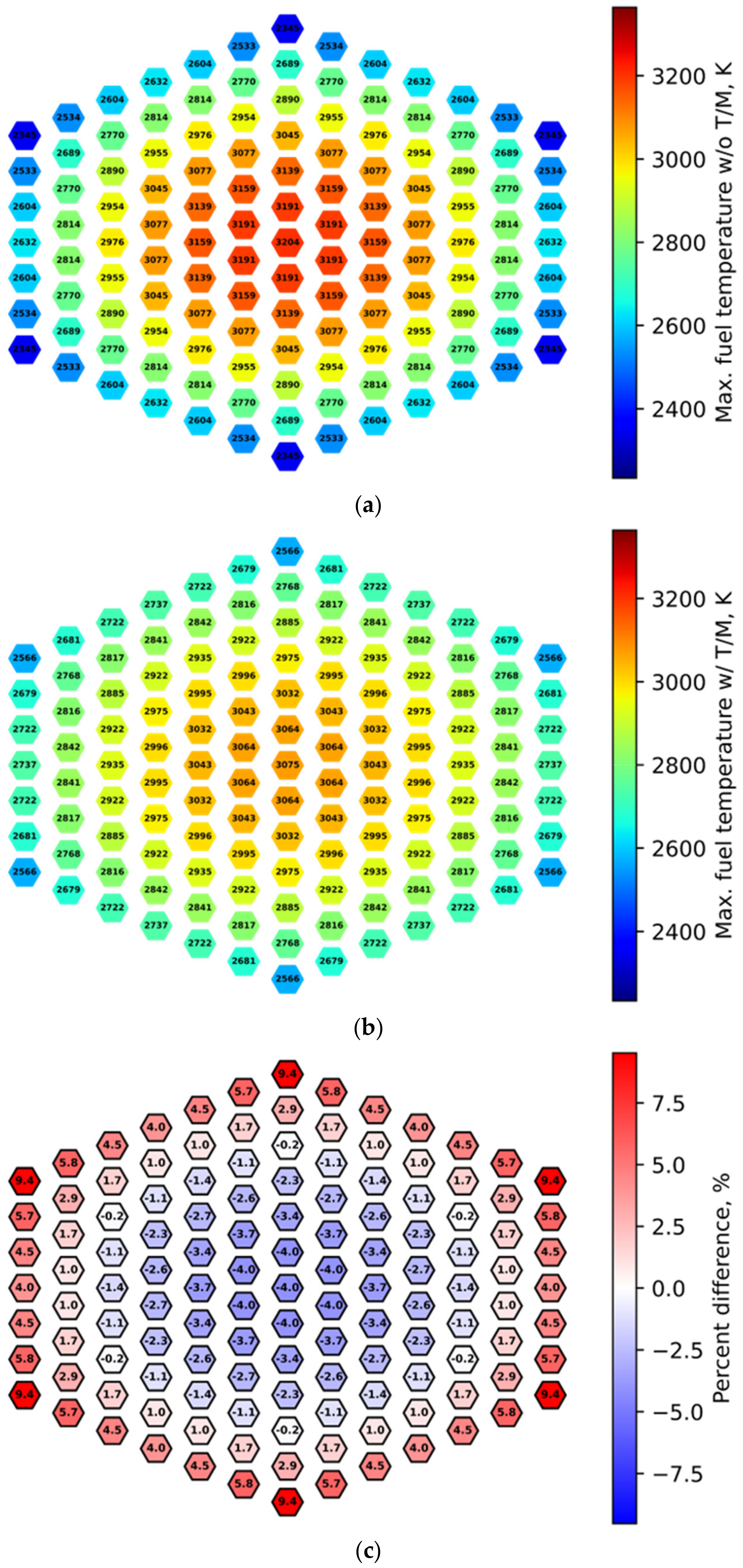
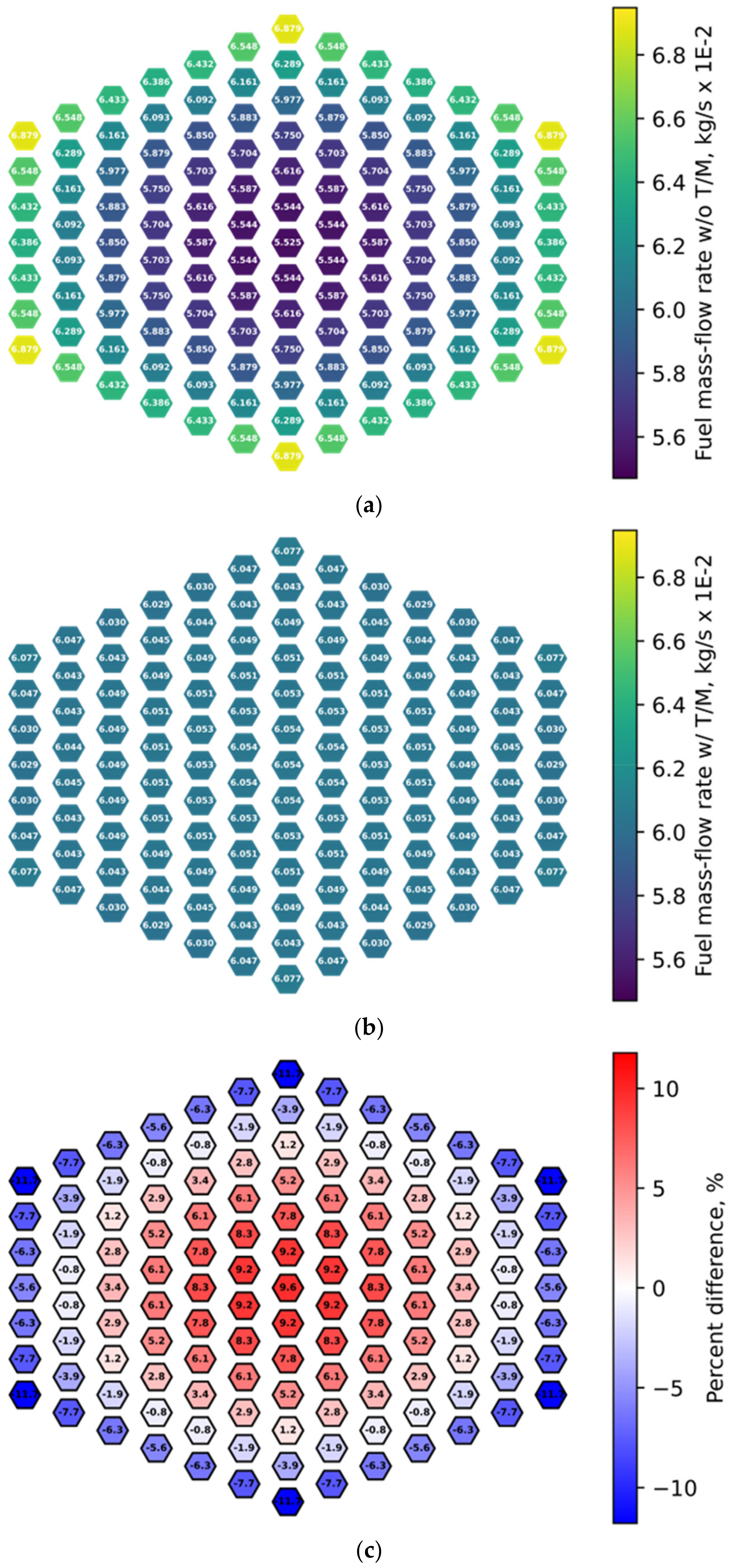
4.1. Importance of Thermo-Mechanical Feedback in Modeling NTP Systems

The objective of this section is to demonstrate the importance of T/M feedback by comparing N+T/H analysis to N+T/H-T/M analysis. In this work, the T/M feedback solution is applied only to the FEs as they experience the most considerable deformation and stress. The T/M solution of the MEs will be the focus of future studies, including the flow distribution balance analysis when the supply and return channels are expanded or contracted. The analysis presented in this section was obtained with the Churchill friction factor correlation applied to solve the FEs on the basis of the recommendations of previous research [26]. No orificing was applied to the FEs to facilitate comparisons between N+T/H and N+T/H-T/M analysis. The primary feedback that T/M has on the T/H solution is decreasing the pressure loss of higher-power channels, thus decreasing the redistribution of mass flow within the reactor core. Higher-power channels experience greater thermal expansion (increase in flow area) and thus reduced pressure losses.
To quantify the convergence of the multiphysics solution, the L-2 norm error defined by Equation (25) was calculated for multiple spatially distributed T/H fields, such as fuel temperature ( T f u e l ), ZrH temperature ( T Z r H ), fuel gas density ( ρ f u e l ), moderator supply gas density ( ρ s u p p l y ), moderator return gas density ( ρ r e t u r n ), and fuel power ( Q f u e l ). These T/H fields are presented in Figure 6 because they have a significant impact on the spatial power distribution within the reactor [6].
l 2 n = X n X n 1 2 X n 1 2
In Equation (25), X is the spatial distribution of interest for consecutive iterations n 1 and n [27]. The trends in Figure 6 demonstrate that temperature, density, and power spatial distributions converged after the sixth iteration. Figure 7 details the excess reactivity for each iteration; the difference in reactivity between the fifth and sixth iteration is within the statistical uncertainty (±7 pcm) of the Monte Carlo solution.
The radial power peaking of each FE in the core with and without T/M feedback is detailed in Figure 8. When comparing Figure 8a,b, it becomes apparent that T/M feedback slightly increases (+0.9%) the maximum radial power peaking. The percent difference between the radial power distributions is detailed in Figure 8c, where the percent difference ( % Δ ) is calculated via % Δ = 100 × X w / T M X w / o T M / X w / o T M , where X is the quantity of interest. A positive %∆ represents where N+T/H analysis underpredicts a given value when compared with N+T/H-T/M analysis. The maximum fuel temperature of each FE is detailed in Figure 9. T/M feedback decreases the maximum fuel temperature by 129 K. Despite the minor increase in radial power peaking, the hot channel maximum fuel temperature decreases as a result of the significant increase in mass flow to the hot channel when T/M feedback is considered. The reduction in solid-fuel temperatures reduces the amount of heat conducted from the central higher-power FE channels to their surrounding ME channels. This, in turn, reduces the local ZrH temperature of the surrounding MEs. Previous research [6] has demonstrated that lower ZrH temperatures increase the local fission rate. Since the local ZrH in the center of the core is reduced when T/M feedback is considered, the radial power peaking increases. The local ZrH temperature has a significant effect on neutron moderation as the thermal peak is shifted with respect to neutron energy [6].
The mass flow distribution of the FEs with and without T/M feedback is compared in Figure 10. It becomes clear when comparing Figure 10a,b that T/M feedback significantly impacts the mass flow distribution within the FE channels as the hot channel experiences a 9.6% increase in mass flow when T/M feedback is considered.
The difference in mass flow distribution is caused by the thermal expansion of coolant channels. The thermal expansion of coolant channels increases the flow area within the FE, resulting in reduced pressure drops, thus, requiring additional mass flow to equalize the pressure drop across the FE channels. The percent difference in the flow area of each FE channel at the core mid-plane (z = 60 cm) with and without thermal expansion is detailed in Figure 11. The mass flow and flow area percent difference distributions illustrate this effect as they have nearly identical shapes. As expected, the hottest channel experiences the greatest increase (+22%) in flow area because of its elevated solid-fuel temperatures.
The outlet bulk coolant temperature distributions with and without T/M feedback are detailed in Figure 12.
Figure 13 compares each component of the friction pressure losses ( Δ P f r i c ) for the hot channel with and without T/M feedback. The current implementation does not consider the impact of sudden contraction/expansion of coolant channels on pressure losses within the FE channels. However, future research will investigate the importance of such effects. The with/without ratio of each parameter is presented as a function of axial height in Figure 13. The Δ P f r i c and acceleration pressure losses ( Δ P a c c e l ) equations are detailed in Equations (26) and (27), respectively, where f is the friction factor, G is the mass velocity, L is the length of the axial layer, D h is the hydraulic diameter of the channel, and ρ is the density of the fluid.
Δ P f r i c = 2 f L D h G 2 ρ ¯
Δ P a c c e l = G 2 1 ρ i n 1 ρ o u t
The mass velocity significantly decreases as the flow area along the channel increases, detailed by the red line in Figure 13. The hot channel pressure losses and bulk coolant pressure obtained via N+T/H and N+T/H–T/M analysis are compared in Figure 14. The decreased mass velocity affects both the Δ P f r i c and Δ P a c c e l as they are both a function of G 2 . The total pressure drop across the FEs is overpredicted by 150 kPa when T/M feedback is neglected. The results in Figure 13 and Figure 14 illustrate the mechanism causing the mass flow distribution differences in Figure 10c.
T/M feedback has an overall beneficial impact on the T/H performance for the design considered in this paper, as the thermal expansion of coolant channels reduces the pressure drop across the FE channels and redistributes mass flow to higher-power channels. When comparing Figure 9c and Figure 10c, it becomes clear that the heat transfer within the hot channel is reduced as the mass flow increases by 9.6%, but the maximum fuel temperature is only reduced by 4.0%. The hot channel heat transfer coefficient, as a function of axial height, is detailed in Figure 15a and demonstrates that T/M feedback has a negative impact on the heat transfer coefficient. Several competing effects are responsible for this behavior. Similar to Figure 13, the with/without ratios for several parameters which influence the heat transfer coefficient and are significantly impacted by T/M feedback are detailed in Figure 15b. Thermal expansion reduces the coolant velocity ( u ) within the channel, which is partially offset by the increase in the hydraulic diameter ( D h ) and density ( ρ ). These competing effects result in a minor reduction in Reynolds number near the exit (z > 80 cm) of the hot channel. Hydrogen’s viscosity ( μ ) and thermal conductivity ( t c ) increase with temperature [28]. The bulk coolant temperature within the hot channel decreases because of the mass flow rate distribution, thus resulting in a decrease in both the μ and t c along the channel. All these factors combined result in the reduction in the heat transfer coefficient within the hot channel.
The maximum VM stress in each FE channel with and without T/M feedback is detailed in Figure 16. When T/M feedback is neglected, the maximum VM stress occurs in the hot channel (Location A). However, when T/M feedback is considered, the maximum VM stress occurs in the FE channel with the highest fuel particle packing fraction (Location B).
The VM stress is commonly used in yielding/fracturing criteria [29] and thermal creep rate correlations [30]. Therefore, the difference in the maximum VM stress and local VM stress distributions should be considered. The FE radial temperature and VM stress profiles for the FE channel at the maximum stress axial layer (z = 82 cm) for location B are detailed in Figure 16. Dashed lines in Figure 17 are used to depict the outer radii of the cladding and fuel meat with T/M feedback (indicated by red lines) and without T/M feedback (indicated by black lines). When T/M feedback is accounted for, the radial mesh is deformed, resulting in the dashed lines moving to the right. Location B’s max VM stress experiences an 11% increase when T/M feedback is considered, which is primarily caused by the local fuel temperature increasing by ~200 K, as detailed in Figure 17a. Figure 17b shows that the greatest VM stress occurs on the exterior of the coolant channel cladding, which is consistent with previous studies [7]. The coefficient of thermal expansion (CTE) mismatch between the fuel matrix and cladding materials has been previously identified as a primary source of thermal stress [7] and has been linked to increased fuel mass loss rates [31]. The FE in location B has the largest CTE mismatch because of the channel-elevated fuel loading (see Figure 4). UN’s thermal expansion coefficient is nearly double that of ZrC and is the primary cause of location B’s elevated VM stresses.
A comparison of several key global parameters is detailed in Table 3. The analysis in this section demonstrates that T/M feedback has a beneficial impact on the T/H performance of the reactor resulting in reduced fuel temperatures and pressure losses; however, it has a slightly negative impact on the T/M performance.

4.2. Friction Factor Sensitivity Study

The analysis detailed in Section 4.1 used the Churchill friction factor correlation to obtain the pressure losses within the FE channels. Previous research has compared various Nusselt number and friction factor correlations and concluded that the variation in the predicted pressure drop between legacy friction factor correlations was acceptable [26]. However, this study did not consider how variations in the pressure drop between correlations would propagate in multichannel problems or be exacerbated by T/M feedback. Additionally, the study did not consider several legacy friction factor correlations which rely on the Reynolds number evaluated at the coolant channel wall conditions ( R e w ), such as the Taylor-II and modified Koo correlation. The Taylor-II correlation was used to analyze the NRX reactor series during the NERVA program [32]. This correlation used the corrected R e w to ensure that predicted friction factors were within ±10 percent of the experimental data [33].
Coupled N+T/H–T/M analyses were performed with several friction factor correlations applied to the FE T/H solution. The considered friction factor correlations were detailed in previous research [6]. No orificing was applied to the FEs in order to allow the mass flow to redistribute naturally within the core. A summary of the analysis is detailed in Table 4. The only global parameter that varies considerably based on the applied friction factor correlation is the pressure drop across the FE channels. Therefore, the authors recommend further research to assess the importance of rebalancing the engine cycle within a multiphysics framework to quantify the impact of the pressure drop on the FE and ME inlet boundary conditions.

5. Summary and Conclusions

Nuclear thermal propulsion systems are being actively investigated by NASA and DARPA as an enabling technology for Mars transit and cislunar operations. The design of such systems will require advanced M&S tools capable of capturing the complex multiphysics feedback present within the reactor core. Previous research has recommended [3,9] and demonstrated [10] that T/M feedback should be accounted for in the multiphysics analysis of NTP reactors. This paper details the thermo-elastic equations solution approach implemented into the ntpThermo code. The approach casts the thermo-elastic equations in the form of the second-order Fredholm integral equation. The primary advantage of this approach is that temperature-dependent properties can be applied within the numerical solution scheme to capture the spatial variation of mechanical properties within each radial node and axial layer. Additionally, the implementation of a coupled N+T/H–T/M sequence into the Basilisk code is described. The coupled N-T/H–T/M sequence was applied to analyze a realistic reactor design with a nonuniform fuel loading pattern and temperature-dependent material properties.
Full-core N+T/H analysis was compared to full-core N+T/H–T/M analysis to demonstrate the importance of T/M feedback. When T/M feedback is neglected, the maximum fuel temperature was overestimated by 129 K, pressure losses across the FE channels were overestimated by 150 kPa, and the maximum VM stress was underestimated by 12 MPa while having only a minor impact on reactivity and local power distributions. The thermal expansion of coolant channels increases the flow area within the FE channels. This significantly reduces the mass velocity and, thus the pressure drop across the FE channels. This reduces the pressure losses within the FE channels. Sensitivity studies revealed that the pressure drop across the FE channels varied considerably on the basis of the friction factor correlation applied to solve the FE channels. Correlations that rely on a corrected Reynolds number, which were used to design the NERVA NRX reactors, predict significantly higher pressure drops. The importance of T/M feedback within a multiphysics solution scheme is case-dependent and can be more or less sensitive in some cases (e.g., higher-power peaking). This paper demonstrates that the T/M feedback should be incorporated into the coupled sequence to accurately capture detailed temperature and stress distributions within the analyzed reactor core.
Future research should include the thermal stress/expansion of MEs and its impact on mass flow distribution within the ME channels.

Author Contributions

Conceptualization, M.K. and D.K.; methodology, M.K. and D.K.; software, M.K. and D.K.; validation, M.K. and D.K.; formal analysis, M.K.; investigation, M.K.; writing—original draft preparation, M.K.; writing—review and editing, M.K. and D.K.; visualization, M.K.; supervision, D.K. All authors have read and agreed to the published version of the manuscript.

Funding

This research was funded by BWX Technologies.

Institutional Review Board Statement

Not applicable.

Informed Consent Statement

Not applicable.

Data Availability Statement

Not applicable.

Acknowledgments

The authors would like to thank Jonathan Witter for his valuable discussion and insights.

Conflicts of Interest

The authors declare no conflict of interest.

References

  1. Gustafson, J.L. Space Nuclear Propulsion Fuel and Moderator Development Plan Conceptual Testing Reference Design. In Proceedings of the Nuclear and Emerging Technologies for Space, Virtual, 26–30 April 2021. [Google Scholar]
  2. Joyner, C.R., II; Jennings, T.; Kokan, T.; Levack, D.J.H.; Reynolds, C. HALEU NTP Update-Subscale Prototype and Full Scale Designs. In Proceedings of the Nuclear and Emerging Technologies for Space, Virtual, 26–30 April 2021. [Google Scholar]
  3. DeHart, M.D.; Laboure, V.M.; Schunert, S. Evolution of MOOSE and MOOSE-Based Tools to Address Analysis Challenges. INL/MIS-21-62652-Revision-0. 2021. Available online: https://inldigitallibrary.inl.gov/sites/sti/sti/Sort_41824.pdf (accessed on 20 October 2021).
  4. Demonstration Rocket for Agile Cislunar Operations (DRACO) Phase 2 and Phase 3. 2022. Available online: https://sam.gov/opp/af490b568d2a438498afa1e80bce63e5/view (accessed on 3 June 2022).
  5. National Academies of Sciences, Engineering, Medicine. Space Nuclear Propulsion for Human Mars Exploration; The National Academies Press: Washington, DC, USA, 2021. [Google Scholar]
  6. Krecicki, M.; Kotlyar, D. Thermal hydraulic modeling of solid-fueled nuclear thermal propulsion reactors part II: Full-core coupled neutronic and thermal hydraulic analysis. Ann. Nucl. Energy 2022, 179, 109397. [Google Scholar] [CrossRef]
  7. Stewart, M.; Schnitzler, B. Thermal, Fluid, and Structural Analysis of a Cermet Fuel Element. In Proceedings of the AIAA/ASME/SAE/ASEE Joint Propulsion Conference & Exhibit, Atlanta, GA, USA, 30 July–1 August 2012. [Google Scholar]
  8. Stewart, M. Thermal, Fluid, and Neutronic Analysis of an LEU Nuclear Thermal Propulsion Core. In Proceedings of the AIAA Propulsion and Energy 2019 Forum, Indianapolis, IN, USA, 19–22 August 2019. [Google Scholar]
  9. Nam, S.; Venneri, P.; Kim, Y.; Lee, J.; Chang, S.; Jeong, Y. Innovative Concept for an Ultra-small Nuclear Thermal Rocket Utilizing a New Moderated Reactor. Nucl. Eng. Technol. 2015, 6, 678–699. [Google Scholar] [CrossRef]
  10. Krecicki, M.; Kotlyar, D. Understanding the Coupled Thermo-Mechanical with Thermal-Hydraulic Effects in Nuclear Thermal Propulsion Systems. In Proceedings of the American Nuclear Society Annual Summer Meeting, Anaheim, CA, USA, 12–16 June 2022. [Google Scholar]
  11. Krecicki, M.; Wang, J.; Kotlyar, D. Thermal Hydraulic Modeling of Solid Fueled Nuclear Thermal Propulsion Reactors Part I: Development and Verification. Ann. Nucl. Energy 2022, 173, 109113. [Google Scholar] [CrossRef]
  12. Peng, X.; Li, X. Thermoelastic analysis of functionally graded annulus with arbitrary gradient. Appl. Math. Mech. 2009, 30, 1211–1220. [Google Scholar] [CrossRef]
  13. Lawton, R.; Prince, W. Rover Graphite Fuel Element Thermal Stress Experiments and Analyses; LA-3849-MS; Los Alamos Scientific Laboratory: Santa Fe, NM, USA, 1967. [Google Scholar]
  14. Krecicki, M.; Kotlyar, D. Low enriched nuclear thermal propulsion neutronic, thermal hydraulic, and system design space analysis. Nucl. Eng. Des. 2020, 363, 110605. [Google Scholar] [CrossRef]
  15. Atkinson, K.; Shampine, L. Solving Fredholm Integral Equations of the Second Kind in MATLAB. ACM Trans. Math. Softw. 2008, 34, 21. [Google Scholar] [CrossRef]
  16. Koelsch, C.; Heflin, S.; Krecicki, M.; Kotlyar, D. Thermo-mechanics Feedback for Nuclear Thermal Propulsion Analysis: Implementation and Application. In Proceedings of the PHYSOR 2022, Pittsburgh, PA, USA, 15–20 May 2022. [Google Scholar]
  17. Leppänen, J.; Pusa, M.; Viitanen, T.; Valtavirta, V.; Kaltiaisenaho, T. The Serpent Monte Carlo code: Status, development and applications in 2013. Ann. Nucl. Energy 2015, 82, 142–150. [Google Scholar] [CrossRef]
  18. Leppänen, J.; Viitanen, T.; Valtavirta, V. Multiphysics Coupling Scheme in the Serpent 2 Monte Carlo Code. Trans. Am. Nucl. Soc. 2012, 107, 1165. [Google Scholar]
  19. Manickam, V.; Kotlyar, D. Implementation of a comprehensive reduced order methodology for transient analysis of nuclear thermal propulsion engines. Nucl. Eng. Des. 2022, 395, 111841. [Google Scholar] [CrossRef]
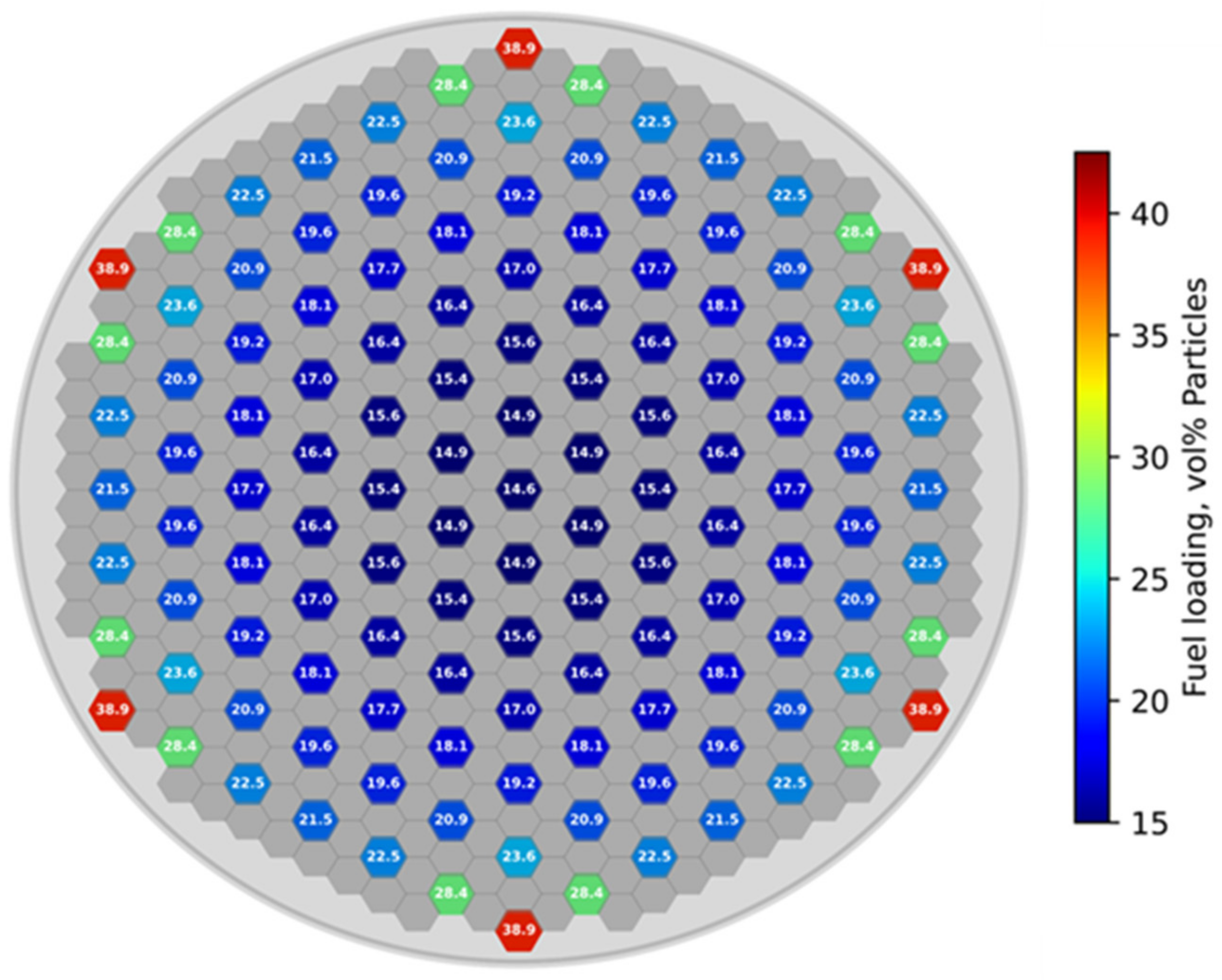
  20. Krecicki, M.; Kotlyar, D. Thermal Performance Sensitivity to Radial Power Flattening Considerations in Nuclear Thermal Propulsion Reactors. In Proceedings of the International Conference on Physics of Reactors 2022, Pittsburgh, PA, USA, 15–20 May 2022. [Google Scholar]
  21. Harrison, R.; Lee, W. Processing and properties of ZrC, ZrN and ZrCN ceramics: A review. Adv. Appl. Ceram. 2016, 115, 294–307. [Google Scholar] [CrossRef]
  22. Kostanovskiy, A.V.; Zeodinov, M.G.; Kostanovskaya, M.E. Thermal Expansion of Zirconium Carbide at 1200–2850 K. High Temp. 2018, 56, 936–937. [Google Scholar] [CrossRef]
  23. Kim, J.; Suh, Y.J. Temperature- and pressure-dependent elastic properties, thermal expansion ratios, and minimum thermal conductivities of ZrC, ZrN, and Zr(C0.5N0.5). Ceram. Int. 2017, 43, 12968–12974. [Google Scholar] [CrossRef]
  24. Hayes, S.L.; Thomas, J.K.; Peddicord, K.L. Material property correlations for uranium mononitride: I. Physical properties. J. Nucl. Mater. 1990, 171, 262–270. [Google Scholar] [CrossRef]
  25. Hayes, S.L.; Thomas, J.K.; Peddicord, K.L. Material property correlations for uranium mononitride: II. Mechanical properties. J. Nucl. Mater. 1990, 171, 271–288. [Google Scholar] [CrossRef]
  26. Nikitaev, D.; Smith, C.; Benensky, K. Comparison of Convective Heat Transfer Correlations and Their Application to Nuclear Thermal Propulsion. In Proceedings of the Nuclear and Emerging Technologies for Space Applications, Cleveland, OH, USA, 9–12 May 2022. [Google Scholar]
  27. Terlizzi, S.; Kotlyar, D. A perturbation-based acceleration for Monte Carlo—Thermal Hydraulics Picard iterations. Part II: Application to 3D PWR-based problems. Ann. Nucl. Energy 2022, 166, 108713. [Google Scholar] [CrossRef]
  28. Fang, Y.; Wang, C.; Tian, W.; Zhang, D.; Su, G.; Qiu, S. Study on high-temperature hydrogen dissociation for nuclear thermal propulsion reactor. Nucl. Eng. Des. 2022, 392, 111753. [Google Scholar] [CrossRef]
  29. Huddleston, R. An Improved Multiaxial Creep-Rupture Strength Criterion. J. Press. Vessel. Technol. 1985, 107, 421–429. [Google Scholar] [CrossRef]
  30. Betten, J. Creep Mechanics; Springer: Berlin/Heidelberg, Germany, 2008. [Google Scholar]
  31. Pelaccio, D.; El-Genk, M. A Review of Nuclear Thermal Propulsion Carbide Fuel Corrosion and Key Issues; NASA-CR-197533; NASA: Washington, DC, USA, 1994.
  32. Westinghouse Astronuclear Laboratory. Thermal and Fluid Flow Analysis Report; WANL-TME-2753; Westinghouse Astronuclear Laboratory: Pittsburgh, PA, USA, 1971. [Google Scholar]
  33. Taylor, M. Correlation of Friction Coefficients for Laminar and Turbulent Flow with Ratios of Surface to Bulk Temperature from 0.35 to 7.35; NASA TR R-267; NASA: Washington, DC, USA, 1967.
Figure 1. Coupled T/H–T/M solution sequence.
Energies 15 07007 g001
Figure 2. Coupled N+T/H–T/M solution sequence.
Energies 15 07007 g002
Figure 3. T/H field mapping to Serpent Model for (a) MEs; (b) FEs.
Energies 15 07007 g003aEnergies 15 07007 g003b
Figure 4. Reactor design: (a) radial core cross-section; (b) axial core cross-section.
Energies 15 07007 g004
Figure 5. Fuel loading pattern.
Energies 15 07007 g005
Figure 6. Comparison of L-2 norm error convergence (a) w/o T/M feedback; (b) w/ T/M feedback.
Energies 15 07007 g006
Figure 7. Comparison of excess reactivity convergence.
Energies 15 07007 g007
Figure 8. Comparison of radial power peaking (a) w/o T/M feedback; (b) w/ T/M feedback; (c) percent difference.
Energies 15 07007 g008
Figure 9. Comparison of maximum fuel temperature (a) w/o T/M feedback; (b) w/ T/M feedback; (c) percent difference.
Energies 15 07007 g009
Figure 10. Comparison of mass flow rate (a) w/o T/M feedback; (b) w/ T/M feedback; (c) percent difference.
Energies 15 07007 g010
Figure 11. Mid-plane (z = 60 cm) flow area percent difference.
Energies 15 07007 g011
Figure 12. Comparison of outlet bulk coolant temperature (a) w/o T/M feedback; (b) w/ T/M feedback; (c) percent difference.
Energies 15 07007 g012aEnergies 15 07007 g012b
Figure 13. Comparison of hot channel pressure loss component ratios.
Energies 15 07007 g013
Figure 14. Comparison of hot channel (a) pressure losses; (b) bulk coolant pressure.
Energies 15 07007 g014
Figure 15. Comparison of the hot channel (a) heat transfer coefficient; (b) heat transfer component ratios as a function of axial height.
Energies 15 07007 g015aEnergies 15 07007 g015b
Figure 16. Comparison of maximum von Mises stress (a) w/o T/M feedback; (b) w/ T/M feedback; (c) percent difference.
Energies 15 07007 g016aEnergies 15 07007 g016b
Figure 17. Comparison of radial (a) temperature; (b) von Mises stress; profile for maximum von Mises stress location in a single flow channel surrounded by fuel.
Energies 15 07007 g017
Table 1. Key design parameters.
ParameterValue
Number of Fuel Elements127
Number of Moderator Elements390
Number of Control Drums18
Poison Vane Thickness0.5 cm
Poison Vane B4C Enrichment95 wt%
Active Core Diameter31.0 cm
Active Core Height120.0 cm
Radial Reflector Thickness11.0 cm
Axial Reflector Thickness10.0 cm
Active Core H:235U Ratio334:1
Total HALEU Mass40.3 kg
235U Enrichment19.75 wt%
Serpent Model Dry Mass2508 kg
Table 2. Temperature-dependent fuel material mechanical properties.
MaterialReferenceProperty
ZrC[21] E T   Pa = 4.16 × 10 11 1.3 × 10 7   T 12958   T 295 K T 2253 K
[22] α T   K 1 = 1.7792 × 10 9   T + 3.5258 × 10 6 1200 K T 2800 K
[23] v = 0.213
UN[24] E T   Pa = 25.8 × 10 6 1 2.375 × 10 5   T 298 K T 1473 K
[25] α T   K 1 = 7.096 × 10 6 + 1.409 × 10 9   T 298 K T 2523 K
v = 0.281
Table 3. Comparison of global parameters.
Parameterw/o T/Mw/ T/MDifference
Excess reactivity, pcm23 ± 738 ± 7+15
Max. fuel temperature, K32043075−129
Max. ZrH temperature, K491479−12
Max. fuel von Mises stress, MPa273296+12
Max. radial power peaking1.101.11+0.01
Fuel pressure-drop506356−150
Fuel max. outlet bulk coolant temperature, K31182964−154
Fuel avg. outlet bulk coolant temperature, K27462749+3
Table 4. Friction factor sensitivity study summary.
With Wall CorrectionWithout Wall Correction
ParameterTaylor-IIModified KooTaylor-IChurchillMcAdams
Max. fuel temperature, K30493052309130753075
Max. ZrH temperature, K481483479479478
Max. fuel von Mises stress, MPa300300293296295
Max. radial power peaking1.1141.1161.1141.1141.115
Fuel pressure-drop, kPa871868150356353
Excess reactivity, pcm47 ± 769 ± 723 ± 738 ± 739 ± 7
Publisher’s Note: MDPI stays neutral with regard to jurisdictional claims in published maps and institutional affiliations.

