
Interoperability Testing of a Smart Home Automation System under Explicit Demand Response Schemes

1
Seidor Italy, External Consultant for Joint Research Centre (JRC), 21027 Ispra, Italy
2
Energy Security, Distribution and Markets Unit, Energy, Transport and Climate Directorate, European Commission, Joint Research Centre (JRC), 21027 Ispra, Italy
3
European Commission, Joint Research Centre (JRC), 1755 Petten, The Netherlands
*
Author to whom correspondence should be addressed.
†
Retired.
Energies 2022, 15(21), 7952; https://0-doi-org.brum.beds.ac.uk/10.3390/en15217952
Submission received: 31 August 2022
/
Revised: 5 October 2022
/
Accepted: 17 October 2022
/
Published: 26 October 2022
(This article belongs to the Special Issue Improving the Energy Efficiency of Buildings)
Abstract
:Interoperability becomes a key issue for smart grid systems, as the interaction between diverse components needs to lead to a normal system operation. In this paper, we test interoperability issues with respect to home automation. In particular, interaction of a home energy management system (HEMS) is examined with an external actor for home/building remote control. We show the importance and the feasibility of remotely controlling domestic loads from outside the house premises, which can be crucial for energy saving operations, such as demand response. The Smart Grid Architecture Model (SGAM) is used, where the different actors are depicted. The interoperability testing methodology for smart grids, developed by our unit, is followed in order to design the necessary tests and execute them. For the experimental part, we develop an HEMS in our lab along with a Home Automation End Device (HAED), used to transform two normal plugs, and consequently, normal loads into smart ones, thus creating a system for home automation and control. The described configuration is only one possible configuration out of the available ones existing in the market for home automation. LabVIEW programming is used in order to realize the actual explicit demand response program through remote load control and scheduling. The results show that explicit demand response can be achieved by an external actor with success and interoperability is preserved.
1. Introduction
The smart grid constitutes the future of the traditional grid, where telecommunication features among devices are added on the energy layer. The modern grid is required to keep up with the integration of renewable energy sources and to guarantee an efficient energy management so as to achieve CO2 emissions. Therefore, automatization is essential for monitoring and control purposes. With numerous smart devices and intelligent electronic devices (IED) being implemented, the grid needs to incorporate different technologies. As a result, interoperability plays a key role in the future smart grid, as it ensures that different components can interact successfully and guarantee the normal operation of the system. The Energy Security, Distribution and Markets Unit of the Joint Research Centre (JRC) has created a methodology for testing interoperability for smart grids [1], which is used in this paper to produce the interoperability test results. This methodology is based on the smart grid architecture model (SGAM) developed by CEN/CENELEC [2].
Among the actors that share interactions from the energy provider to the end user, it is important to ensure correct system operation and interoperability with respect to the home energy automation system and smart devices. Automatization and load control within the house can be crucial for energy saving operations, such as demand response programs, and can involve the end user in becoming a more active player in the smart grid with the minimum effort required. The topic of smart home and home energy management have attracted the scientific interest with several articles on the subject. In [3], an energy management system (EMS) is suggested for residential microgrids in order to minimize their operational cost. In [4], an EMS is proposed for efficient use of power generated by a smart home, where every building and appliance have their own controller. In [5], a home energy management system (HEMS) is proposed, where scheduling takes into account the users’ needs apart from electricity rates. A method is presented of shifting the loads within the house. Special focus is given on the end users’ behavior; data are collected regarding load consumption and customer behavior for obtaining better results. Smart home automation and remote control of devices is the topic in [6], where the home appliances were controlled through an android application. In [7], a survey is presented related to the use of reinforcement learning in HEMS applications.
In [8], a way to achieve remote control functionality of the air condition is proposed. In [9], the authors present an algorithm in order to shift loads within the home. This algorithm takes also into account the relationship between electricity prices and daily power demand. In [10], energy management is performed for homes through a fog computing platform. All the devices are connected to the platform, and the services algorithms are implemented on the platform. The user can monitor their power consumption through an interface. In [11], they examine a smart home use case and focus on the network limitations and potential improvements needed for future networks. A cloud-based management system is proposed in [12] for smart homes, where two protocols, the HTTP (hypertext transfer protocol) and the MQTT (message queue telemetry transport) are used for controlling smart home systems. An internet-of-things concept for energy management in smart homes is examined in [13], where WiFi solutions are proposed to control loads.
In [14], an online energy management algorithm is developed in order to schedule domestic loads so as to minimize the sum of the energy cost and thermal discomfort cost for a smart home. The cost effectiveness of appliances is examined also in [15], where an optimization problem of smart home appliances usage is examined. The scheduling of devices such as air conditioning and heating systems is the topic in [16], where a new HEMS is proposed to schedule home devices. A new HEMS is also proposed in [17], where the integration of renewables and energy storage systems is investigated using information regarding electricity selling and electricity utilization.
In terms of interoperability and the smart home/building field of research, in [18], it a review is presented where interoperability issues are examined among different techniques for the evaluation of buildings. This review presents the applicability of qualitative and quantitative non-destructive techniques for diagnosis of cultural buildings. As can be observed, there are many relevant studies on the subject of home automation and home energy management systems. However, none of these articles focus on the interoperability issues between an external actor and the devices within the house, and none of these articles present interoperability tests, which is fundamental for the whole system’s functioning. In addition, in the literature review that has been performed, focus is not given on the interaction between the HEMS itself and an external actor who controls home devices remotely for the purposes of explicit demand response. This external actor is in fact the entity that implements the demand response program, and it can be, for instance, a DSO, an aggregator, a flexibility provider, etc. In the rest of the paper, we refer to such an entity as the External Actor or equivalently Actor A, which is in accordance to the CEN/CENELEC terminology. In [9], there is an algorithm for load shifting within the house, whereas no remote scheduling and control is proposed. In [5], there is also a technique on load shifting within the house with focus on users behavior, whereas in [6], the devices are switched on and off by the user through their mobile phone. In [11], the focus is on the network limitations and possibilities for network improvement. In [10], Home Energy Management is examined with a focus on the consumer for monitoring the appliances through a platform. In addition, we see that there are several articles for smart appliances scheduling, as in [14,15,16,17]. However, there is a lack in interoperability studies, followed by and complemented by interoperability tests in all the aforementioned literature.
The research design for this work has been mainly to investigate the existing literature with respect to potential HEMSs and interoperability issues, identify gaps, and contribute to the research. Thus, all cited references are relevant to this topic. This paper complements what is found in the literature, as it adds interoperability issues and interoperability tests results that are examined for an HEMS for the first time, to the best of our knowledge. For this scope, a well-defined methodology is followed, which is described in detail in [1]. In addition, we emphasize the role of the external actor and the importance of remote load scheduling that is according to the external actor’s needs for explicit demand response, naturally without violating customer rights and comfort level. We show the importance of a home energy management system (HEMS) and its interaction with the rest of the energy actors. We depict these interactions on the Smart Grid Architecture Model (SGAM) and we highlight the fact that interoperability needs to be preserved under remote load scheduling for demand response purposes. An example of a lab configuration is shown, presenting the interaction between actors and the remote load scheduling of devices within the house done by an external actor (Actor A) outside the house premises. Thus, the objective of this work is two-fold: to address interoperability issues for an HEMS and to show that remote load control can take place from an actor outside the house premises. This work complements a previous work [19], where a tutorial has been presented on applying the interoperability testing methodology; the use case described entailed the entire chain of actors from the energy provider to the end user and it depicted their interactions under demand side flexibility programs. Apart from the tutorial, other works followed, mainly focusing on the interaction of smart meters with the actors outside the house premises. This work complements the previous ones, since it focuses on the interactions of an external actor with systems within the house and examines system interoperability related to home automation issues. For this scope, we give an experimental example of a home automation system performing interoperability tests, we show how explicit demand response can take place through remote load control and we highlight the benefits of such remote control in terms of energy savings.
For the example presented here, the functionality of the remote control has been implemented through the internet, as in many realistic explicit demand response programs. One home has been considered for the interoperability tests given with two smart plugs; however, the concept remains the same for more smart plugs within the home and the proposed scheme can be expanded to a larger number of homes without loss of generality. LabVIEW programming has been used to transform the normal plugs into smart ones, which can be scheduled remotely. The external actor is able to change the status of the plugs dynamically while ensuring continuous functionality of the two plugs, meaning that they remain in this status (either on or off) while they are paused. Lab experiments are performed and measured data are used to create the energy diagrams that prove the applicability of the explicit demand response program through remote load control. For this purpose, real consumption data have been used to demonstrate the validity of the proposed model of remote scheduling and control of domestic loads and the automatic switch off in case a consumption limit is exceeded. The benefits of home automation and explicit demand response schemes are shown by comparing the results achieved with the situation when no load scheduling is applied. In addition, we show that interoperability is preserved in the sense that the devices control by an external actor does not compromise the system, whereas home automation can be done within or outside the house.
Figure 1 presents in a straightforward way the methodological approach applied in this work. As the figure reveals, we apply the Smart Grid Interoperability Testing Methodology, where all steps are visible. For the use case creation, which is the first step of the structured Methodology, it is necessary to define the functionalities for the explicit demand response scenario we are testing. The Use Case defines the operational functionalities that need to be dealt with. These functionalities are directly linked to the way the experimental procedure is performed.
The rest of the paper is structured as follows. Section 2 shows the methodology used for performing the interoperability tests, presents the use case and its SGAM representation, and shows the BAPs and BAIOPs. Section 3 discusses operational aspects, i.e., how the methodology is applied, and describes the experimental configuration developed in order to execute interoperability tests and the programming needed for the explicit demand response schemes. Section 4 describes the interoperability test steps followed and how these are executed, and thus, showing all operational aspects of how the structured methodology is applied. Section 5 presents a discussion on results and future work, while Section 6 concludes the paper.
2. SGAM Framework and Use Case Description—Interoperability Methodology Followed
The Smart Grid Architecture Model (SGAM) has been the outcome of the Reference Architecture working Group mandated by the EU’s 490 mandate [20] entitled “Smart Grid Mandate–Standardization Mandate to European Standardization Organizations (ESOs) to support European Smart Grid deployment”. The SGAM framework defines five layers of interoperability, namely the component layer, communication layer, information layer, functional layer, and business layer. The SGAM representation is shown in Figure 2.
The SGAM model serves as guidance for interoperability testing, indicating that interoperability tests can take place in one of the five defined layers. The Joint Research Centre of the European Commission has created a methodology for interoperability testing, taking into account the specifications of SGAM and the five layers [1].
In this section, we explain the Use Case examined in this paper. The actors are depicted in the Smart Grid Architecture Model (SGAM) and their interactions are shown. This use case has been inspired by [19], in which a tutorial has been presented on how to apply the interoperability testing methodology. In that paper, a detailed use case is presented, where all actors are considered from the energy provider to the end user, and out of which demand response/demand side flexibility applications can be better explained via the full chain of interactions of all actors. Although in our previous works, we mainly focused on the interaction of smart meters [21,22], in this work, we focus on the interaction of an external actor with the energy home system within the house premises. The link of interest here is of vital importance since automation within the house can contribute to energy savings. On the other hand, we show that it is important to preserve interoperability when appliances are controlled remotely, i.e., outside the house.
Thus, the scope is to show that interoperability is preserved even when appliances are controlled by an external actor outside the house premises. The Use Case described here entails normal appliances within the house, a home automation end device, an energy management system within the house, and an external actor. Such an external actor, according to CEN/CENELEC [23], can be an energy provider, an Energy Services Provider, an aggregator, etc. This actor can interact with the systems and components in the home, such as the home energy management system (HEMS). Subsequently, this HEMS can control the home automation end device (HAED), which in turn controls the normal appliances within the house.
Figure 3 shows the representation of the use case on the component layer of SGAM architecture and the interactions among actors. We take into account that the scheduling of devices within the house works in case it is done by the customers themselves. Thus, we focus on the interaction of the external actor with the energy management system within the house. As can be observed from Figure 3, the appliances within the house are controlled by an automation end device, and subsequently, by the energy management system. In this paper, we provide an example of how such a system and the relevant interactions can be realized, which will be explained in detail in the following sections. Figure 3 also shows the interaction of several more actors, which complete the full chain of interaction for this use case. Therefore, a smart meter is shown interacting with a data concentrator (NNAP) and Actor B, who according to CEN/CENELEC [23] is the actor that controls the metering channel. These three actors are used in the example given in this paper in order to visualize the results for the explicit demand response schemes. The smart meter, data concentrator, and the control center (Actor B) are the means for us to visualize the experimental results explained thoroughly in following sections. Figure 4 shows the representation of the use case on the communication and information layers.
The representation of the use case on the SGAM layers shows the possible standards that can be used in each link of interaction. As shown in Figure 4, the possible standards are in some cases a group of standards that can be used (i.e., interface C, G2, H2, H3, M, etc.). The list of standards for these interfaces are defined in [19,24], where the reader is redirected in order to find the tables that show the complete list of standards that can be used for the specific links. According to the interoperability testing methodology, after mapping the use case to the SGAM layers of interest, the Basic Application Profiles (BAPs) and Basic Application Interoperability Profiles (BAIOP) need to be defined. The BAPs are based on the information flows that are exchanged between actors. Each BAP corresponds to one standard/protocol to be used for each link of interaction. The Basic Application Interoperability Profiles take into account one BAP, equivalently one solution, for each of the interaction links between actors.
The methodology defines that there is only one tested piece of equipment, whereas the rest of the actors comprise the testbed. In our use case, the equipment tested is considered to be the Customer Energy Management System and the link of interest is its interaction with the external Actor A. It is considered that the standards used for the known functioning links are already fixed and no further investigation takes place. Thus, the BAPs for these links are considered to be fixed. Table 1 shows the BAPs for the equipment/actors comprising the test bed.
On the other hand, the BAP(s), and subsequently, the BAIOP(s) with respect to the tested equipment, are defined based on the equipment’s specifications. In this work, we consider for the link of interest that internet connection is used; thus, the IEEE 802.11 standard among the available ones (interface H3). The BAIOPs are basically describing the interoperability tests to be performed for the use case. Here, we have tests referring to the communication and the information layer. Table 2 and Table 3 show the description of the tests to be performed and the various steps that need to be followed. The BAIOPs presented here are in accordance to the Smart Grid Interoperability Testing Methodology, as developed and described in [1], which we follow in this work. The test steps reveal the functionalities that we want to test in accordance to the explicit demand response scenario we implement. The test verdict here shows the conditions under which a test can be considered successful or not. In Section 3, we discuss all the operational aspects for the realization of the interoperability tests, i.e., how the testbed has been created, how the HEMS and HAED have been constructed and the usage of LabVIEW for programming the remote load scheduling, the pause and restart function, as well as the switch off for emergency function. On the other hand, the interoperability tests themselves along with the results obtained are presented in detail in Section 4. Table 2 and Table 3 show the description of interoperability tests, as these are defined according to the methodological approach we have used. We present them here to give a complete picture of the methodology used from use case creation to the BAIOP definition.
3. Experimental Configuration—Operational Aspects to Apply and Execute the Interoperability Tests
In this section, we present the operational aspects needed in order to realize and execute the interoperability tests. First, we provide a description of the testbed, which we created for the needs of the use case in order to realize the interoperability tests. We provide the operational aspects of the functionalities tested for the explicit demand response scenario; in other words, we describe how these functionalities are performed in practice. The functionalities we test here are: schedule of appliances; dynamically change load schedule; automatic switch off of loads. In this section, we present thoroughly how these functionalities take place, under the subsection “Remote Control Functions”. We present the operational aspects of remote scheduling with the possibility to pause, restart, and dynamically alter at any moment the loads’ operation, whereas we finally give the details of automatic switch off of loads in case of an emergency. Such functionalities are important for the realization of the explicit demand response scenario and for the execution of the interoperability tests between the HEMS and the external actor. All these operational aspects are the means to execute the interoperability tests and obtain the results.
3.1. Testbed
In this subsection, we show which configuration is used in order to represent the Home Energy Management System (HEMS) in our lab experiments. The HEMS used is only an example of the possible configurations that can be used in practice, as discussed in the literature. It should be noticed that the proposed solution is only to show the interaction of HEMS with an external actor and how remote control can be achieved from outside the house for the execution of an explicit demand response program.
Figure 5 shows the block diagram used for conducting the experiments of this work. We focus on one house; however, the same concept can be applied to more houses without loss of generality, since the remote control is realized through internet. It is assumed that the Data Acquisition and Control Platform and the Customer Terminal Block are in the customer premises. These devices are used in order to represent an HEMS configuration and a Home Automation End Device (used to transform normal plugs into smart ones), respectively. The external actor should be able to control and program the two plugs determining the exact time moments they will be switched on and off. Moreover, it should be possible to change the status of the plugs at any moment, always taking into consideration the end-user profile and preferences in a way that guarantee maximum availability of the provided energy. Depending on the agreement between the end-user and the energy provider, it should be possible to alter the status of the plug quite frequently as long as the contract allows it. In addition, if desired, a consumption limit could be set for safety reasons; in case it is exceeded, the plug could switch off automatically. This is the focus in this paper, and these functions should be executed independently from the HEMS used. For the latter functionality, a different approach is usually applied for critical plugs, such as those supplying energy to alarm systems, medical devices, internet gateways, sensors, surveillance devices, etc., which require continues power supply (24/7). Such plugs are not considered part of the demand side management planning and cannot be managed through the remote control functionality of the energy provider. In most practical cases, the plugs that can participate in such a program could be those used to charge electric vehicles (EV) or those that can be used in load shifting programs. For example, it may not be that important to start charging an EV when returning at home in the afternoon, but to have it fully changed by next morning when the car is really needed, or it may not make any difference if the washing machine starts a couple of hours later when the energy demand will decrease.
The HEMS used here is composed by the Data Acquisition and Control Platform, which is a National Instruments (NI) PXIe-1082 device, comprising the external chassis, an embedded controller (National Instruments PXIe-8840), and three acquisition cards. The acquisition board used here is the National Instruments PXI 2586 card that entails 10 relays. LabVIEW programming is used for controlling the HEMS.
Two of the available relays have been used at the acquisition board, without loss of generality. The experiment carried out in this work can be easily extended to more relays. We created a custom terminal block, which represents the Home Automation End Device (HAED) in order to connect the aforementioned relays to two normal plugs. Domestic loads can be connected to the plugs, which are transformed in smart programmable plugs thanks to the Data Acquisition and Control Platform and the software that controls it.
Apart from the above infrastructure, a smart meter is used in order to capture the consumption data, which is forwarded to the data concentrator. These data are afterwards collected by a computer that represents the control center of the energy provider (Actor B). However, it is assumed that the external actor A, dealing with the remote loads control has access to the energy consumption data (communication of data between Actor B and Actor A is assumed), which allows the actor A to take dynamic decisions on the status of the plugs.
The smart meter and the data concentrator communicate with each other through Power Line Communications (PLC) technology, namely the PRIME specification. This is a solution widely used in practice. These devices and their equivalent software can be considered as representative for real systems. It is highlighted that the smart meter, the data concentrators are used as part of the testbed to enable the experiments, prove the importance of home automation and load control. Analyzing their functionality and the software used for their control is out of the scope of this paper. The explicit demand response program is intended for any domestic loads. In this example, we have used a programmable load to emulate the consumption of domestic loads. This programmable load can produce resistive, inductive, and capacitive output up to 3 kW. It can also give the diagram of a consumption profile that is scheduled.
3.2. Remote Control Functions
The remote control of loads has been accomplished through programming of our HEMS (Data Acquisition and Control Platform) with LabVIEW. It is assumed that the HEMS is situated at the customers premises, whereas specific initial settings are imposed in order for the control to take place by the external actor A. A LabVIEW interface has been created in order to program our HEMS, and consequently, control the plugs by the external actor. In this subsection, we explain the main concept behind the programming of HEMS and we show the steps taken to accomplish the remote load control. We show how the main functionalities described in the BAIOP steps can practically take place with our lab equipment. In different configurations, i.e., different HEMS, other configurations may be necessary. The ultimate scope is to achieve interoperability and apply the steps described in the BAIOP(s). It is also important that the external actor achieves remote control without manual real-time control to be required.
3.2.1. Front Panel User Interface
The front panel interface enables the HEMS user to realize the loads control. Such control can take place by the customers themselves or remotely by an external actor A, which is our case of interest. This remote control is enabled through internet connection. The front panel that has been created contains basic information for the user and it enables them to fully control the programmable plugs with simple actions. First of all, two Boolean buttons have been inserted one for each of the two relays used. These buttons enable the user to manually control the status of the relays. There are several options to handle the flow of the plugs’ status, listed as follows:
- Start: This option allows the program to initiate.
- Stop: This option stops the experiment but the user does not exit the program.
- Pause: This pauses the program—the plugs remain at the status they have when the pause is pressed. When deactivated, the external actor can restart from any desired step. For this reason, a question pops up asking from which step the experiment should be continued. For the duration of the pause, the external actor can modify and add steps at the imported sequence that controls the plugs’ status.
- Quit: This stops the experiment and exits the program.
The last three options can be selected any time during the experiment.
For both relays, it is possible to import a sequence specifying the exact time moments the two relays will be switched on or off. Figure 6 and Figure 7 show the front panel interface created and the options for the external actor for this example. In addition, the interface indicates that there is protection offered for both relays in case a specific power threshold is surpassed.
The interface allows the user to visualize the status of the relays through the two graphs shown in Figure 7, one for each relay. The graphs give an overview of the plugs’ status scheduling versus time. Figure 7 shows that the second plug is always on, while the first one changes status, which will be explained in following sections.
3.2.2. Relay Status Scheduling and Program Execution
This is an important part on the programming work, since it entails the execution of the relay status alteration, and thus, the remote plugs scheduling and control. The following steps take place:
- An iterative loop is created for all the steps of the experiment, which is defined by the entries of the imported sequence. The iterative loop can be interrupted in case of the pause function.
- For every step of the executed sequence, the relay status is transformed into numbers. The resulting number Rs is compared to ‘1’. If Rs = 1, then the relay and, consequently, the plug is switched on. Otherwise, if Rs = 0, the relay is off. We have also defined a specific time period of 100 msec that the routine waits so as to make sure that the relay is actually turned on or off.
- The relay remains on or off for a specific time period (duration).
- At the end of the routine, the relay is brought to its initial state and the routine can restart.
There is always the option to quit the routine.
3.2.3. Pause Function and Restart at the Desired Step
The function described at this point is the one that allows the external actor to take dynamic decisions based on the overall energy consumption by controlling specific loads dynamically. The following steps are followed:
- When the pause function is selected, the normal sequence of the step for the plugs status is interrupted. The timers deciding for the step duration are deactivated.
- The relays/plugs remain at their current status (whichever it is).
- The external actor can import a new sequence or not.
- When the pause function is deselected (with a new sequence inserted or not), the external actor can restart at any desirable step, probably skipping several steps.
This kind of scheduling is useful when the external actor A wants to perform dynamic changes and alterations with respect to the plugs. Therefore, according to the grid conditions and information received, such as load forecasting, weather conditions, etc., the loads scheduling can be altered at any moment.
3.2.4. Automatic Plug Switch off in Case of Emergency
This part serves in order to impose a restriction on a load in case of a risk of overloading in a crisis situation. This process is designed for those loads that are not included in the list of those that can be remotely controlled, and at the same time, they are not critical loads that need a 24/7 power supply. This is a middle category of loads, where the default status of the equivalent plug is always on, but can be switched off during a crisis situation, such as an environmental disaster, when exceeding a predefined consumption limit. A special routine has been created that allows the external actor to control such loads in case the consumption exceeds a certain limit. Loads can be categorized to the ones that can be easily scheduled and controlled and the ones that can be controlled only during crisis situations by an external actor A. Before proceeding with such an action, it should be controlled if loads belonging to the first category are on.
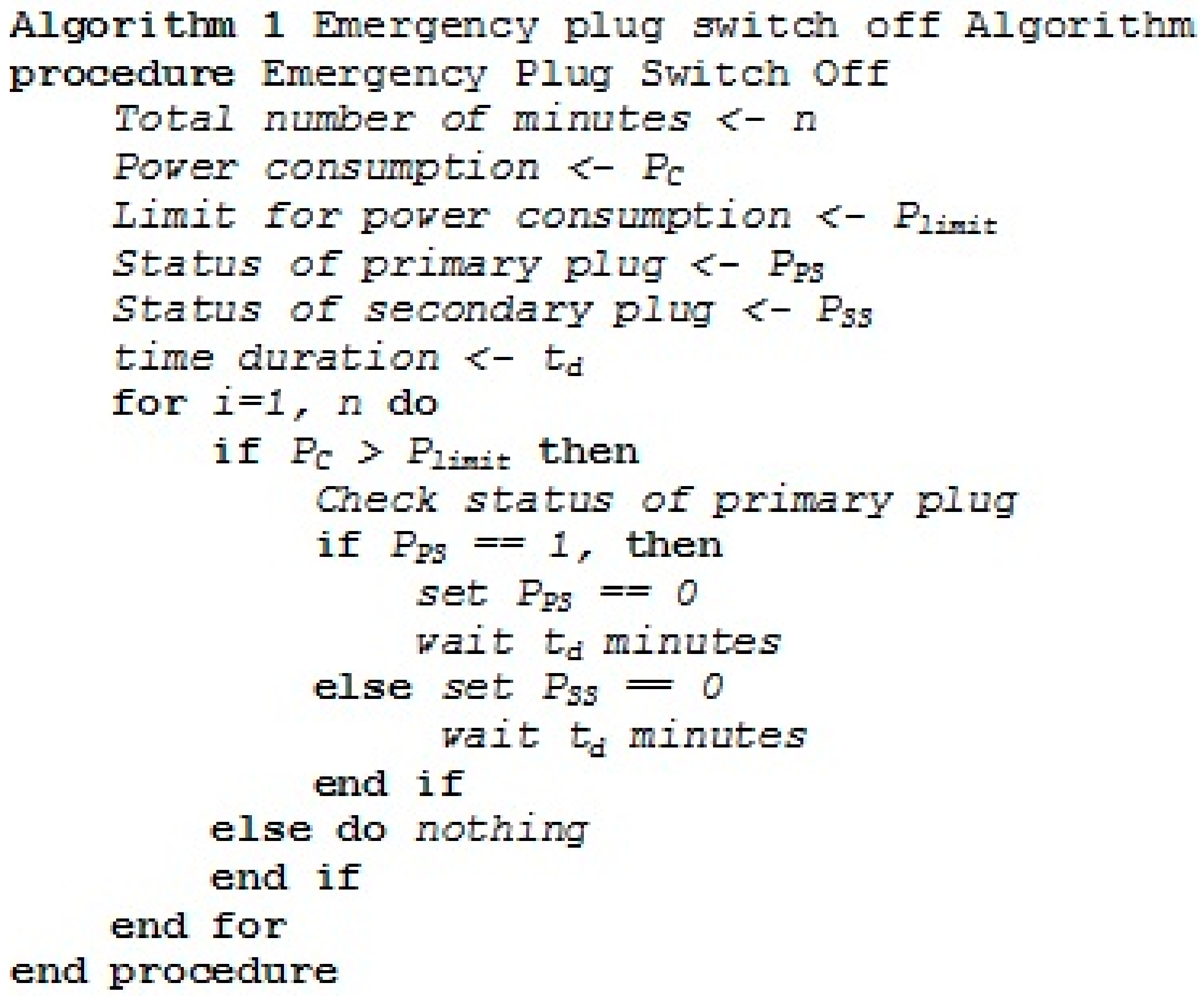
To achieve this, we take advantage of the smart meter recordings. The consumption is monitored with high frequency. We set the smart meter recordings to be available every minute at the external actor A. The most recent reading of power consumption is fed as input to the LabVIEW program, and if it exceeds a certain limit, either the primary or the secondary loads are switched off. In particular, the sequence of steps to be followed is summarized in Figure 8.
For accomplishing the aforementioned algorithm, the power consumption needs to be available each minute at the external actor A, meaning that communication through Actor B (controlling the metering channel) and Actor A is assumed; these data are fed to the LabVIEW interface at Actor A. In this case, we are interested only in the active power registered by the smart meter.
Thus, protection is activated in case the power exceeds a specific limit. Protection for the relay of secondary plug is activated after the protection for the relay of the primary plug. A timer is used for td minutes in order for the relay(s) to be activated again. We used Plimit = 2 kW, td = 5 min.
4. Test Results for the Interoperability Layers—Following the BAIOPs Procedure
In this section, we explain the test procedure and results concerning the communication and information interoperability layer, following the steps explained in Table 2 and Table 3, described in Section 2. It is reminded that we use the methodological procedure described in Section 2, for implementing the interoperability tests, whereas the operational aspects described in Section 3 have been applied. In other words, for the test execution and the results presentation, we take one by one the steps of the tests as these are described in the equivalent BAIOPs; afterwards, we describe how these steps are implemented and we present the final results. Firstly, we present the test description and result for the Communication interoperability layer. For the Information interoperability layer, we first describe the parameters and the configuration for the interoperability test steps, which help the reader comprehend the nature of the tests and what has been done in order to achieve the results; afterwards, we give the results for the tests regarding this layer.
4.1. Communication Interoperability Layer
As has been explained, the external actor controls the residential loads through LabVIEW programming of the HEMS (Data Acquisition and Control Platform) connected to the internet. It is supposed that the terms and conditions under which the explicit demand response takes place are defined by a contract between the customer and the external actor. It is assumed that the remote control takes place through certain settings done at the HEMS and that the HEMS and the HAED (which is the Customer Terminal Block) are in the customer premises. The steps explained in Table 2 (BAIOP for the communication layer) take place.
The final message “control transferred appears” indicates a PASS for the communication layer interoperability test.
After these settings, the external actor A can take control of the residential loads that are assigned to the plugs. This way, a simple house is transformed into a smart one with the aim at achieving efficient energy management. It is assumed that the remote connection takes place between the external actor and the HEMS, within the house premises, through a dedicated link, and a public address, which is not related to the customer’s private internet connection (Step 1). This way, the customer is not involved in the internet settings and functionality; the connection takes place independently and the customer only needs to consent to the terms and conditions of the agreement. A motivation for the customers can be possible discounts on their final bill or different tariffs can be used for this scope. In general, market issues are not examined here. This work has been carried out in our lab environment, where a link with a private address has been used. However, the concept remains the same and the conclusions are applied without loss of generality.
Through the front panel interface described in Figure 6, the external actor can import a sequence that can schedule the functionality of the plugs. Therefore, energy management is achieved through the internet with an easy-to-use tool. Internet connection, such as every data transmission link connection, naturally has its limitations, such as packet losses, delays, etc. In this work, we do not focus on the improvement of such limitations. It is assumed that the connection is sufficient for transferring the sequence responsible for the remote control and scheduling each time the external actor decides to impose such a sequence. It is assumed that extreme connectivity losses will not be present, which can be realistic with a modern typical internet connection.
4.2. General Test Parameters for the Information Interoperability Layer
In this and the following subsections, we focus on how the tests are performed and the results for the information interoperability layer, and thus, ensuring correct operation and system interoperability between the external actor A and the HEMS for the explicit demand response scheme. Table 3 is taken into account for these tests, as this is presented in Section 2, which represents the information layer BAIOP.
The general considerations and setting parameters are described as follows:
- The functionality of two plugs has been programmed for a duration of 10 h, through the LabVIEW interface. The duration has been selected so as to represent a day from 10:00 to 20:00. Longer planning can take place without alteration of the routines used. The plugs are scheduled to turn on and off for specific time intervals, which are chosen according to the category of the loads.
- Loads are connected to the two plugs. Plug number one (connected to relay 0) provides electricity to a cooling device with nominal consumption 390 W. The cooling device is considered to be permanently connected to the plug. Plug number 2 (connected to relay 1) provides electricity to a programmable load. This load has a consumption curve that can be up to 3 kW. For this experiment, we have chosen to have a variable consumption curve with time, which can represent the variable loads connected to a domestic plug during a day.
- For the plugs’ planning, the schedule shown in Figure 7 is used. This schedule takes into account the nature of the loads behind the plugs.
- It is considered that the cooling device is permanently connected to plug 1, which is consistent with what happens in a real home with respect to air conditioners. Such a load belongs to the category of loads that could be shifted in case load consumption needs to be curtailed of shifted. This is because the functionality of a cooling device can be interrupted and restarted later without decreasing much the comfort of people, provided that there is a tolerance in a marginal temperature increase for a short duration. Other devices, such as cooking devices or televisions, would be categorized in the devices that are least likely to be shifted or curtailed, since that would lead to highly decreasing the residents’ comfort. Even devices such as the dishwasher or the washing machine that could be shifted for enabling load consumption reduction cannot be interrupted while functioning. For this reason, a cooling device has been chosen for load shifting/curtailing.
- With respect to the second plug, we have used a programmable load that gives as output a variable consumption curve throughout the experiment. The load consumption obtained by the programmable load is considered to represent any domestic load or combination of them (i.e., televisions, DVD player, computer, printer, lamps, charger, etc.), which are turned on and off throughout the 10 h. The functionality of the electrical devices is indicative; the scope is to create a variable consumption. Figure 9 shows the consumption curve that is created by the programmable load in time. We consider only the active power corresponding to the electric load consumption.
- The two plugs are connected to a smart meter that is designed for residential use with a limit of 3 KW.
- The accumulative energy consumption of the two plugs as well as the power required is recorded by the smart meter.
4.3. Configuration for the Interoperability Steps
At this point, the configuration for the test steps is described and the parameters are taken into account. The steps described here are referring to the steps presented in the BAIOP for the information layer (Table 3), as they are presented in Section 2. Thus, we show here all the details for executing the test steps shown in Table 3.
- Step 1: For Step 1, as described in the BAIOP for the information interoperability layer, a PASS is required from the communication interoperability layer. This PASS is obtained, as explained in Section 4.1.
- Step 2: Scheduling of specific loads within the house
It is assumed that the need for load shifting is around noon and evening hours, when consumption is expected to be high, due to people being more active within the house (cooking, etc.). Therefore, for the experiment needs, the remote control of the cooling device takes place between 12:00–14:00 and 17:00–20:00. Between these hours, the plug is scheduled to be on for 10’ and off for 5′ alternatively. It is also assumed that the cooling device itself is intended to be switched on according to the needs of the final customer; this schedule is shown in the following table and is independent of the time slot when the remote control takes place (set by the external actor).
The intended usage shown in Table 4 is indicative. Other usage patterns can be applied without loss of generality. It should also be noted that the usage plan of the device itself is different from the plug scheduling, since the plug can be set to be on but the device can be turned off either way.
Since the second plug is used to feed any residential loads, it is assumed that it cannot be scheduled by an external actor.
- 3.
- Step 3: Automatic switch off of loads in case of emergency:
- Plug 1 (air cooling device) should be the first one to be turned off in case of an emergency.
- Even if the second plug is not scheduled by an external actor, it can be switched off in emergency situations, for example if the consumption exceeds a limit, in order for the energy provider to save energy and maintain grid stability. Therefore, the explicit demand response program indicates that the second plug will always be on unless an emergency occurs.
- For the experiment purpose, the status of plugs is considered to be determined for every minute according to the algorithm described in Figure 8, where Plimit = 2000 W, td = 5 min. The limit of 2000 W and the duration of 5 min are indicative. Another value can be inserted as limit or as duration without loss of generality.
- The instantaneous power values are used for testing the automatic plug switch off in case of emergency.
- The LabVIEW program obtains the power consumption value every minute and according to it, the emergency switch off is activated or not. In case the total power exceeds a certain value, here 2000 W, and the first plug is off, then plug 2 that controls the programmable load goes off for 5 min. Thus, if the emergency switch off is applied, and there is no load actually connected to plug 1, then the switch off of plug 2 will take place the next minute, according to this algorithm.
- 4.
- Step 4: Possibility of dynamically altering the load scheduling:
- The pause function created can be tested very easily, since it can be executed by the external actor manually. Given that the grid conditions change dynamically, it is likely that the initial scheduling is not the ideal one throughout the day. In our example, we suppose that the grid conditions change and there is energy surplus between 12:30–13:00 (e.g., from photovoltaics). Therefore, there is no need for load curtailing within this time slot. The external actor can alter the plugs scheduling so as the first plug (cooling device) is always on within this period.
- The external actor decides to dynamically change the relay scheduling between 12:30–13:00. The time slot selected is indicative. After 13:00, the original plan is followed.
- 5.
- Step 5: running the experiment
The experiment is run and the results are verified through consumption graphs, as is shown in the following subsection.
4.4. Results for the Information Interoperability Layer
Here, we show the results for the interoperability tests performed for the information layer. The experiments are executed according to the configurations explained above and the operational aspects, as explained in Section 3, whereas the steps followed for the interoperability tests are according to the BAIOP presented in Section 2, where the interoperability testing methodology has been explained.
To verify the results and for comparison reasons, we first ran the experiment without the plugs remote control, and thus, under no explicit demand response program. Thus, plug 1 entails a steady consumption of the cooling device equal to 390 W according to the times indicated by Table 4, whereas plug 2 entails consumption according to Figure 9. The consumption data are recorded by the smart meter of the testbed and are forwarded to the data concentrator and further on to the computer for smart meter data monitoring. From the data collected and through the software options that the data concentrator offers, we deduct the energy diagram for the load consumption of the plugs. The energy consumption was recorded every 5 min by the data concentrator. Note that the Advanced Metering Infrastructure (AMI) system available here is used in order to help us prove the functionality of the proposed system. Analyzing the software options for the data concentrator is out of the scope of this work. Figure 10 shows the overall energy consumption in steps of 5 min and presents the experimental results.
For the load scheduling and control, we initially apply the plugs status shown in Figure 7. However, the concept of changing a plug’s status in off-state is applied in case the consumption exceeds a certain limit. Therefore, in this experiment, an emergency switch put in off-state the plug 2 twice, when the consumption is higher than 2000 W. In addition, the external actor decides to dynamically change the status of the cooling device to on between 12:30–13:00. Therefore, we expect to have a different consumption in specific time periods. Table 5 shows the overall changes that are introduced by the external actor along with the initial plan for the two plugs determined by the end user.
As can be concluded from the above table, the changes expected on the consumption of the plugs with respect to the situation where no explicit demand response takes place, should occur at the time slots: 130′ to 150′, 220′ to 240′, and 430′ to 570′, due to alternating between on and off of the plug 1, and 350′ to 360′ and 555′ to 560′, due to emergency switch off of plugs. Figure 10 also shows these time periods where a different consumption is expected with the explicit demand response scheme, marked with red bars.
After executing the experiment and applying all the configurations in the experimental process, we obtain the results for the energy consumption achieved when the explicit demand response program takes place. Figure 11 shows these experimental results. As can be illustrated from Figure 10 and Figure 11, the automated load control scheme works, meaning that the loads consumption takes place according to the scheduling plan that we have imposed. It is obvious from Figure 11 that there is lower energy consumption for specific time periods, with respect to what we would have with no load control and monitoring, which is in accordance to the time periods where a different consumption pattern is expected (Figure 10). Therefore, load control can be achieved through a user-friendly interface, where normal plugs can be transformed into smart ones that can be programmed in advance and their status can be altered dynamically. In addition, we have performed an emergency switch-off of a specific plug, in case consumption exceeds a certain limit in an automatic way.
As is obvious, all functionalities for the selected explicit demand response program have been accomplished by the external actor outside the house premises, namely, schedule of appliances, dynamically change load schedule, and automatic switch off of loads. This has been shown clearly through experiments that we have executed in the lab, following the smart grid interoperability methodology and applying all operational aspects. Therefore, we have shown that the HEMS can be controlled remotely by the external actor and interoperability is preserved. The results shown in this section prove that a “PASS” is obtained for the information interoperability layer, as this is indicated in the information interoperability BAIOP.
5. Discussion and Future Work
The paper shows the importance of the interaction between an external actor outside the house premises and an HEMS, found within the house premises, and how interoperability is preserved. To show these interactions and prove interoperability, we first take into account the smart grid interoperability methodology developed by the Energy Security, Distribution and Markets Unit of the Joint Research Centre [1]. This methodological approach takes into account the SGAM model and multiple interoperability layers, and it is explained in Section 2. In this paper, we take into account the communication and information layer to examine the system interoperability. The communication layer interoperability ensures that the external actor establishes successful communication with the HEMS, whereas the information layer interoperability ensures that the remote control functionalities for the explicit demand response program indeed take place. In this work, we have created an HEMS based on available lab equipment and have shown how control can take place by an external actor. The particular HEMS is only an example out of numerous options for home automation systems that can be available. It is important to achieve the explicit demand response program and assure home automation. For such an explicit demand response scenario, we have selected specific functionalities that need to be checked, namely, schedule of appliances, dynamically change load schedule, and automatic switch off of loads in case of an emergency. For the execution of the interoperability tests and for proving the functionalities mentioned, we have applied all necessary operational aspects, from the design of the HEMS and the HAED to programming with LabVIEW the functionalities of the demand response program. The following actions summarize the steps followed to arrive to the results, where the link between the literature and our results is obvious:
- The smart grid interoperability testing methodology has been followed: the use case has been created and represented on SGAM and the BAPs and BAIOPs have been defined, determining the interoperability tests steps.
- The functionalities to check for the selected explicit demand response scenario have been defined: schedule of appliances, dynamically changing the load schedule, and automatically switch off of loads in case of an emergency.
- The operational aspects for the tests’ execution have been dealt with: design of HEMS and HAED and LabVIEW programming for functions such as pause and restart and switch off.
For the communication layer we focus on the connection between the external actor and the HEMS. Internet connection is used for this scope with a dedicated link and a public address not linked to customer’s private internet connection. Table 6 summarizes the steps followed to ensure interoperability and the outcome of our experiments. Table 6 links the steps, as these are indicated in Section 2, in Table 2, with the actions taken to realize them in our lab experiment: it shows the actions taken from the customer’s point of view (at HEMS) as well as from the external actor’s point of view in order to establish communication between the HEMS and the external actor. The tests show that communication is established, which equals to a successful interoperability test at the communication layer. The linking of the results to the literature is clear: the interoperability test steps are defined according to the smart grid interoperability testing methodology and the results summarized in Table 6 show the outcome of each action in order to reach to the final outcome of the tests for the communication layer, which has been a “PASS”.
For the information interoperability layer, we focus on the successful operation of specific functions, such as the actual remote load scheduling with the possibility to dynamically change the load scheduling plan and automatic switch off of loads in case of emergency. These are functions considered to be important for remote load control and particularly for explicit demand response scenarios. The practical part of the implementation has been explained in detail in this work; however, this is only an example of an implementation, whereas the important thing is to show that an explicit demand response program can indeed take place. Table 7 shows the steps that are followed and the experimental outcome after their execution. Table 7 links the steps, as these are indicated in Section 2, in Table 3, with the actions taken to realize them in our lab experiment: it shows all operational aspects that have been performed for the tests’ execution. Table 7 shows clearly that the functionalities chosen for the explicit demand response scenario have been executed, thus making up part of the interoperability tests. The linking of results to the literature is obvious: the smart grid interoperability testing methodology has been followed in order to perform tests between the HEMS and the external actor, which prove the feasibility of the selected explicit demand response scenario, with its listed functionalities being performed successfully. The final outcome has been a “PASS”, meaning that interoperability for the information layer has been maintained, or in other words, that the external actor can take full control of the HEMS within the house remotely.
With respect to the operational aspects needed to execute the interoperability tests, an HEMS is realized in the lab along with a HAED assumed to be situated within house premises, which transform normal home plugs and subsequently loads into smart ones. The HEMS used is only an example, whereas focus is given in interaction issues that can affect interoperability.
As for future work, it is intended to test more HEMS configurations and ensure that explicit demand response programs can be achieved when different systems are used with the same results. Interaction with energy smart appliances is also one of the objectives. The scope is to prove explicit demand response programs functionality, which is an important topic for future energy saving programs. The smart home lab and the interoperability lab of the Energy Security, Distribution and Market Unit of the Joint Research Centre, along with the infrastructure available, including smart home devices and intelligent systems can contribute towards this direction.
6. Conclusion
This paper deals with interoperability between an HEMS and an external actor outside the house premises. The structured Smart Grid Interoperability Testing Methodology, developed by the Energy Security, Distribution and Markets Unit of the Joint Research Centre (JRC), has been used and interoperability tests have been performed. For this scope, the Use Case has been defined and represented on the SGAM, the tested link has been identified, the BAPs have been defined, and the BAIOPs have been created. Interoperability tests have been performed according to the developed BAIOPs with respect to the communication and the information layer of the SGAM. For the experimental part, we have built an HEMS and a HAED in order to perform the interoperability tests. As a second step, we selected the functionalities for a representative demand response program: actual scheduling of devices, possibility to change the schedule, and automatic switch off possibility in case of an emergency. The necessary testbed settings have been performed and LabVIEW programming has been used. The interoperability tests have been described thoroughly and the results reveal that all functionalities have been carried out with success. Thus, the test results show that interoperability is preserved between the HEMS and an external actor. In addition, the feasibility of remotely controlling domestic loads has been examined with success, revealing a great potential for demand response programs.
In general, the paper has dealt with two important topics of the smart grid: explicit demand response program functionalities that can be performed from outside the house premises and interoperability issues supported by the equivalent test results for the interaction between HEMS and an external actor, which prove that interoperability is preserved. This interaction plays a significant part in the global sustainable development efforts and has a direct impact on the way users can optimize energy consumption. Thus, the paper can be an important guide for future works in the sector of home automation for a more efficient smart grid and the support of global decarbonization efforts.
Author Contributions
Conceptualization, N.A.; Data curation, N.A.; Formal analysis, N.A.; Methodology, N.A.; Project administration, M.M.; Resources, E.K.; Supervision, E.K. and M.M.; Validation, E.K.; Writing—original draft, N.A.; Writing—review and editing, E.K. and M.M. All authors have read and agreed to the published version of the manuscript.
Funding
This research received no external funding.
Informed Consent Statement
Not applicable.
Acknowledgments
We would like to thank our former colleague, Fausto Bonavitacola, for helping in realizing the experiments for this work.
Conflicts of Interest
The authors declare no conflict of interest.
Abbreviations
| AMI | Advanced Metering Infrastructure |
| BAP | Basic Application Profile |
| BAIOP | Basic Application Interoperability Profile |
| CEN/CENELEC | European Committee for Stnadardization/European Committee for Electrotechnical Standardization |
| EMS | Energy Management System |
| ESO | European Standardization Organization |
| EV | Electric Vehicle |
| HAED | Home Automation End Device |
| HEMS | Home Energy Management System |
| HTTP | Hypertext Transfer Protocol |
| IED | Intelligent Electronic Device |
| JRC | Joint Research Centre |
| LNAP | Local Network Access Point |
| MQTT | Message Queue Telemetry Transport |
| NNAP | Neighborhood Network Access Point |
| PLC | Power Line Communications |
| SGAM | Smart Grid Architecture Model |
References
- Papaioannou, I.; Tarantola, S.; Lucas, A.; Kotsakis, E.; Marinopoulos, A.; Ginocchi, M.; Olariaga-Guardiola, M.; Masera, M. Smart Grid Interoperability Testing Methodology, EUR 29416 EN; Publications Office of the European Union: Luxembourg, 2018; ISBN 978-92-79-96855-6. [Google Scholar] [CrossRef]
- CEN/CENELEC-ETSI Smart Grid Set of Standards version 4.0 final Oct 2016. Available online: https://www.cencenelec.eu/ (accessed on 22 August 2022).
- Al-Ani, O.; Das, S. Reinforcement Learning: Theory and Applications in HEMS. Energies 2022, 15, 6392. [Google Scholar] [CrossRef]
- Nazabal, J.A.; Fernandez-Valdivielso, C.; Falcone, F.J.; Matias, I.R. Energy Management System proposal for efficient smart homes. In Proceedings of the International Conference on New Concepts in Smart Cities: Fostering Public and Private Alliances (SmartMILE), Gijon, Spain, 11–13 December 2013; pp. 1–5. [Google Scholar]
- Chen, S.; Liu, T.; Gao, F.; Ji, J.; Xu, Z.; Qian, B.; Wu, H.; Guan, X. Butler, Not Servant: A Human-Centric Smart Home Energy Management System. IEEE Commun. Mag. 2017, 55, 27–33. [Google Scholar] [CrossRef]
- Shinde, A.; Kanade, S.; Jugale, N.; Gurav, A.; Vatti, R.A.; Patwardhan, M.M. Smart Home automation system using IR, bluetooth, GSM and android. In Proceedings of the International Conference on Image Information Processing (ICIIP), Shimla, India, 21–23 December 2017. [Google Scholar]
- Nasir, M.B.; Hussain, A.; Niazi, K.A.K.; Nasir, M. An Optimal Energy Management System (EMS) for Residential and Industrial Microgrids. Energies 2022, 15, 6266. [Google Scholar] [CrossRef]
- Zhang, L.; Yan, R.; Sun, H.; Qian, Y. A wireless general air-conditioner remote-controller for smart homes. In Proceedings of the International Conference on Sensing Technology (ICST), Sydney, Australia, 4–6 December 2017. [Google Scholar]
- Khemakhem, S.; Rekik, M.; Krichen, L. Optimal appliances scheduling for demand response strategy in smart home. In Proceedings of the International Conference on Sciences and Techniques of Automatic Control and Computer Engineering, Monastir, Tunisia, 21–23 December 2017. [Google Scholar]
- Al Faruque, M.A.; Vatanparvar, K. Energy Management-as-a-Service Over Fog Computing Platform. IEEE Internet Things J. 2016, 3, 161–169. [Google Scholar] [CrossRef]
- Sahinel, D.; Akpolat, C.; Khan, M.A.; Sivrikaya, F.; Albayrak, S. Beyond 5G Vision for IOLITE Community. IEEE Commun. Mag. 2017, 55, 41–47. [Google Scholar] [CrossRef]
- Lee, Y.-t.; Hsiao, W.-h.; Huang, C.-m.; Seng-cho, T.C. An Integrated Cloud-Based Smart Home Management System with Community Hierarchy. IEEE Trans. Consum. Electron. 2016, 62, 1–9. [Google Scholar] [CrossRef]
- Khan, M.A.; Sajjad, I.A.; Tahir, M.; Haseeb, A. IOT Application for Energy Management in Smart Homes. Eng. Proc. 2022, 20, 43. [Google Scholar] [CrossRef]
- Yu, L.; Jiang, T.; Zou, Y. Online Energy Management for a Sustainable Smart Home with an HVAC Load and Random Occupancy. IEEE Trans. Smart Grid 2019, 10, 1646–1659. [Google Scholar] [CrossRef] [Green Version]
- Molla, T.; Khan, B.; Moges, B.; Alhelou, H.H.; Zamani, R.; Siano, P. Integrated optimization of smart home appliances with cost-effective energy management system. CSEE J. Power Energy Syst. 2019, 5, 249–258. [Google Scholar] [CrossRef]
- Luo, F.; Ranzi, G.; Wan, C.; Xu, Z.; Dong, Z.Y. A Multistage Home Energy Management System with Residential Photovoltaic Penetration. IEEE Trans. Ind. Inform. 2019, 15, 116–126. [Google Scholar] [CrossRef]
- Dinh, H.T.; Yun, J.; Kim, D.M.; Lee, K.; Kim, D. A Home Energy Management System with Renewable Energy and Energy Storage Utilizing Main Grid and Electricity Selling. IEEE Access 2020, 8, 49436–49450. [Google Scholar] [CrossRef]
- Tejedor, B.; Lucchi, E.; Bienvenido-Huertas, D.; Nardi, I. Non-destructive techniques (NDT) for the diagnosis of heritage buildings: Traditional procedures and futures perspectives. Energy Build. 2022, 263, 112029. [Google Scholar] [CrossRef]
- Andreadou, N.; Papaioannou, I.; Masera, M. Interoperability Testing Methodology for Smart Grids and Its Application on a DSM Use Case—A Tutorial. Energies 2019, 12, 8. [Google Scholar] [CrossRef] [Green Version]
- Smart Grid Mandate: Standardization Mandate to European Standardisation Organisations (ESOs) to Support European Smart Grid deployment, DG ENER, European Commission, Mar 2011. Available online: https://energy.ec.europa.eu/index_en (accessed on 22 August 2022).
- Andreadou, N.; Lucas, A.; Tarantola, S.; Poursanidis, I. Design of Experiments in the Methodology for Interoperability Testing: Evaluating AMI Message Exchange. Appl. Sci. 2019, 9, 1221. [Google Scholar] [CrossRef] [Green Version]
- Poursanidis, I.; Andreadou, N.; Kotsakis, E.; Masera, M. Absolute Scoring Scheme for Interoperability Testing of Advanced Metering Infrastructure on Demand Side Management. In Proceedings of the e-Energy ’18: Proceedings of the Ninth International Conference on Future Energy Systems, Karlsruhe, Germany, 12–15 June 2018; pp. 391–392. [Google Scholar] [CrossRef]
- Sustainable Processes, CEN-CENELEC-ETSI Smart Grid Coordination Group. Nov 2012. Available online: https://www.cencenelec.eu/media/CEN-CENELEC/AreasOfWork/CEN-CENELEC_Topics/Smart%20Grids%20and%20Meters/Smart%20Grids/smartgrids_sustainableprocesses.pdf (accessed on 20 July 2022).
- Smart Grid Reference Architecture, CEN-CENELEC-ETSI Smart Grid Coordination Group. 2012. Available online: https://www.cencenelec.eu/media/CEN-CENELEC/AreasOfWork/CEN-CENELEC_Topics/Smart%20Grids%20and%20Meters/Smart%20Grids/reference_architecture_smartgrids.pdf (accessed on 20 July 2022).
Figure 1.
Methodological approach followed in this work.

Figure 2.
SGAM model and Interoperability Types [2].
Figure 2.
SGAM model and Interoperability Types [2].

Figure 3.
Representation of the use case on the SGAM component layer.

Figure 4.
Representation of the use case on the SGAM (a) communication layer and (b) information layer.
Figure 4.
Representation of the use case on the SGAM (a) communication layer and (b) information layer.

Figure 5.
Block diagram of the devices used for the experiments.

Figure 6.
Front panel interface for remote control of the plugs—options for the external actor.

Figure 7.
Front panel interface for remote control of the plugs—relay status diagram.

Figure 8.
Algorithm followed for the emergency plug switch off.

Figure 9.
Consumption curve created by the programmable load (Plug 2).

Figure 10.
Energy consumption without load scheduling and control—expected changes at time slots shown with red bars.
Figure 10.
Energy consumption without load scheduling and control—expected changes at time slots shown with red bars.

Figure 11.
Energy consumption with load scheduling and control.


Table 1.
BAPs for the equipment comprising the test bed.
| Standard | Interaction Link between Actors | Interoperability Layer |
|---|---|---|
| EN 62056 | NNAP—Actor B | Information |
| EN 62325 | Actor B—Actor A | Information |
| EN 50090 | Actor A—HEMS | Information |
| EN 62056 | Smart meter—LNAP | Information |
| EN 62056 | LNAP—NNAP | Information |
| ETSI TS 121 101 | NNAP—Actor B | Communication |
| EN 62325 | Actor B—Actor A | Communication |
| EN 50090 | Actor A—HEMS | Communication |
| EN 50090 | Smart meter—LNAP | Communication |
| ITU-T G. 9904 | LNAP—NNAP | Communication |
Table 2.
BAIOP for the communication layer.
| Interoperability Layer | Communication |
|---|---|
| Summary of the Test | The HEMS needs to be controlled by the external Actor A, so that explicit demand response schemes are realized through remote load scheduling. |
| The HEMS needs to be recognized by the external actor. It needs to be controlled by the external actor, which in turn means that load control within the house is enabled. The connection needs to be independent from customers characteristics. | |
| Test Purpose | To test the interaction of the external actor and the HEMS |
| Test Description | |
| Step 1 | A dedicated link and a public address, which is not related to the customer’s private internet connection |
| Step2 | Settings at customer point:
|
| Step 3 | Settings at the external actor point:
|
| Step 4 | Test verdict: PASS: A message appears: “control transferred”, which means that the remote control is successful. FAIL: Otherwise: the communication is not established. |
Table 3.
BAIOP for the information layer.
| Interoperability Layer | Information |
|---|---|
| Summary of the Test | The HEMS needs to be automatically controlled by the external actor outside the house premises. |
| The external actor needs to be able to perform scheduling for specific loads within the house through the HEMS. The external actor needs to be able to dynamically alter this schedule for the loads according to an excess or not of energy production. The external actor needs to be able to perform automatic switch off of specific loads within the house in case of an emergency. | |
| Test Purpose | To test the interaction of the external actor and the HEMS. |
| Test Description | |
| Step 1 | A PASS in the communication layer is necessary. |
| Step2 | The schedule of specific loads within the house needs to be programmed. |
| Step 3 | Additive functions need to be programmed:
|
| Step 4 | The above functions need to be tested in practice—in an experimental configuration. |
| Step 5 | Test Verdict: PASS: in case Actor A can control the loads within the house remotely; thus, an explicit demand response program is executed, in case the functions programmed are actually executed. FAIL: otherwise. |
Table 4.
Plan of using the device connected to Plug 1—managed by the user.
| Hour | Status |
|---|---|
| 10:00–11:00 | Off |
| 11:00–13:00 | On |
| 13:00–13:30 | Off |
| 13:30–16:00 | On |
| 16:00–17:00 | Off |
| 17:00–19:30 | On |
| 19:30–20:00 | Off |
Table 5.
Overall changes introduced by the external actor to the two plugs.
| Time | Plan by the User—Plug 1 | Plan by the User—Plug 2 | Remote Scheduling of Plug 1 (Cooler)—Plan (12:00—14:00) (17:00—20:00) | Dynamic Changes by the External Actor | Emergency Switch off due to Exceeding the Limit | Final Changes for Plug 1 | Final Changes for Plug 2 |
|---|---|---|---|---|---|---|---|
| 10:00–11:00 | OFF | ON | NO | NO | NO | NO | NO |
| 11:00–12:00 | ON | ON | NO | NO | NO | NO | NO |
| 12:00–12:30 | ON | ON | YES–plug 1 alternates between ON (10′) and OFF (5′) | NO | NO | Yes, plug 1 alternates between ON (10′) and OFF (5′) | NO |
| 12:30–13:00 | ON | ON | YES—plug 1 alternates between ON (10′) and OFF (5′) | Yes—Plug 1 goes on instead of off | NO | NO | NO |
| 13:00–13:30 | OFF | ON | YES—plug 1 alternates between ON (10′) and OFF (5′) | NO | NO | NO (the plug is either way off according to user’s needs) | NO |
| 13:30–14:00 | ON | ON | YES—plug 1 alternates between ON (10′) and OFF (5′) | NO | NO | YES—plug 1 alternates between ON (10′) and OFF (5′) | NO |
| 14:00–16:00 | ON | ON | NO | NO | Yes, between 15:50–16:00 | Yes, between 15:50–16:00 | Yes, between 15:50–16:00 |
| 16:00–17:00 | OFF | ON | NO | NO | NO | NO | NO |
| 17:00–19:30 | ON | ON | YES—plug 1 alternates between ON (10′) and OFF (5′) | NO | Yes, between 19:15–19:20 | Yes, plug 1 alternates between ON (10′) and OFF (5′) Yes, plug 1 goes off between 19:15–19:20 | NO (turning off plug 1 is enough to be below the limit of 2000 W) |
| 19:30–20:00 | OFF | ON | YES—plug 1 alternates between ON (10′) and OFF (5′) | NO | NO | NO (plug 1 is already off according to user’s needs) | NO |
Table 6.
Steps for communication layer interoperability and outcome of experiments.
| n. | Steps | Outcome |
|---|---|---|
| 1 | A dedicated link and a public address which is not related to the customer’s private internet connection is established. | Successful |
| 2 | Settings at customer point:
|
|
| 3 | Settings at the external actor point:
|
|
| 4 | Test verdict PASS: A message appears: “control transferred”, which means that the remote control is successful. FAIL: Otherwise: the communication is not established. | PASS |
Table 7.
Steps for communication layer interoperability and outcome of experiments.
| n. | Steps | Outcome |
|---|---|---|
| 1 | A PASS in the communication layer is necessary | Covered by the communication layer experiments |
| 2 | The schedule of specific loads within the house needs to be programmed | Successful programming is achieved |
| 3 | Additive functions programmed:
|
|
| 4 | The above functions need to be tested in practice—in an experimental configuration | A successful experimental configuration is established and Steps 2 and 3 are executed |
| Test Verdict: PASS: in case Actor A can control the loads within the house remotely; in case the functions programmed are actually executed FAIL: otherwise. | PASS |
Publisher’s Note: MDPI stays neutral with regard to jurisdictional claims in published maps and institutional affiliations. |
© 2022 by the authors. Licensee MDPI, Basel, Switzerland. This article is an open access article distributed under the terms and conditions of the Creative Commons Attribution (CC BY) license (https://creativecommons.org/licenses/by/4.0/).
Share and Cite
MDPI and ACS Style
Andreadou, N.; Kotsakis, E.; Masera, M. Interoperability Testing of a Smart Home Automation System under Explicit Demand Response Schemes. Energies 2022, 15, 7952. https://0-doi-org.brum.beds.ac.uk/10.3390/en15217952
AMA Style
Andreadou N, Kotsakis E, Masera M. Interoperability Testing of a Smart Home Automation System under Explicit Demand Response Schemes. Energies. 2022; 15(21):7952. https://0-doi-org.brum.beds.ac.uk/10.3390/en15217952
Chicago/Turabian StyleAndreadou, Nikoleta, Evangelos Kotsakis, and Marcelo Masera. 2022. "Interoperability Testing of a Smart Home Automation System under Explicit Demand Response Schemes" Energies 15, no. 21: 7952. https://0-doi-org.brum.beds.ac.uk/10.3390/en15217952
Note that from the first issue of 2016, this journal uses article numbers instead of page numbers. See further details here.