
Arrangement of LEDs and Their Impact on Thermal Operating Conditions in High-Power Luminaires

1
Department of Industrial Electrical Engineering and Automatic Control, Kielce University of Technology, 7 Tysiąclecia Państwa Polskiego Str., 25-314 Kielce, Poland
2
Department of Power Electronics and Power Engineering, Rzeszow University of Technology, Wincentego Pola 2, 35-959 Rzeszow, Poland
*
Author to whom correspondence should be addressed.
Energies 2022, 15(21), 8142; https://0-doi-org.brum.beds.ac.uk/10.3390/en15218142
Submission received: 29 September 2022
/
Revised: 25 October 2022
/
Accepted: 28 October 2022
/
Published: 1 November 2022
(This article belongs to the Special Issue Energy Efficiency of the Buildings)
Abstract
:Solid-state light sources are currently the fastest-growing group of light sources, replacing the previously used discharge and incandescent light sources. Thermal operating conditions of LEDs (Light Emitting Diode) play an important role in t maintaining long service life and constancy of luminous-electrical parameters. In the field of illumination, the service life parameter of light sources is important for the costs of maintenance of the illumination system, while the maintenance of the value of certain light parameters over time, such as luminous flux, color temperature and color rendering index, is related to the aesthetic effect of the illumination. In addition, limiting the junction temperature of solid-state light sources is particularly important in high-power luminaires dedicated to flood illumination. One of the elements shaping the thermal operating conditions of multi-source LED luminaires is the number of luminaires used, their arrangement, and the distance between LEDs installed on the MCPCB (Metal Core Printed Circuit Board) substrate. This article presents the results of simulation studies, realized using CFD (Computational Fluid Dynamics) software, where the temperature distribution and the junction temperature of the LED panel were determined for different configurations and distances between the LEDs. The results obtained were analyzed and conclusions were drawn based on them. Thermal tests performed and presented in the article cover scientific issues related to shaping the temperature distribution of the LED panel. They make it possible to determine the influence of thermal couplings between the sources, related to their number, distance and the value of the forward current, on the final temperature of the LED junction temperature. The presented research results may constitute auxiliary materials for designers of lighting luminaires, especially high-power luminaires, where a large number of high-power LED sources are installed in close proximity.
1. Introduction
LEDs, thanks to their numerous advantages, have found application in many areas of lighting technology. High luminous efficacy—currently exceeding 200 lm/W [1]—long service life, wide range of color temperature CCT (correlated color temperature), high value of color rendering index CRI (color rendering index) or resistance to mechanical shock have made these light sources applicable in many areas of indoor lighting (including office, industrial lighting), as well as outdoor lighting (illumination, road or sports lighting) [2,3,4,5,6]. The most commonly used here are high-power LEDs, characterized by a power value, depending on the value of the forward current IF, ranging from a few to several watts [7,8]. A luminaire for which, as in the case of flood illumination, a high value of luminous flux is required, and which illuminates the work surface from a considerable distance, is characterized by a power in the range of several dozen to several hundred watts. Obtaining the required parameters of the luminaire (power, luminous flux Φ, luminous efficacy, CCT, CRI) is realized by grouping a considerable number of LEDs in close proximity, which together can obtain the assumed value of luminous flux. An example here is a 48 W luminaire for illumination, where 16 LEDs have been installed in close proximity (Figure 1a) and a 100 W road lighting luminaire with 36 LEDs (Figure 1b).
In addition to the advantages mentioned above, solid-state light sources also have some disadvantages, the main limitation being the significant thermal impact on the luminous-electrical performance and service life. Only part of the power supplied to the LEDs is converted into luminous flux, while the rest, up to 80%, is lost as heat (Equation (1)) [9,10,11].
where: PH—heat power, Po—optical power, IF—forward current, VF—forward voltage and Pe—electrical power.
In addition, the small area of a junction and a current value of up to 2 A translates into high thermal power densities of 300–500 W/cm2, resulting in an increase in the junction temperature Tj. Prolonged high junction temperature Tj can lead to degradation of the characteristics of the junction materials and significantly shorten the service life of light sources [12]. It also affects the decrease in luminous flux Φ and luminous efficacy, change in color temperature CCT and color rendering index CRI [11,13,14]. For most high-power solid-state light sources, the junction temperature Tj cannot exceed 150 °C [15,16], so rapid heat dissipation from the solid-state junction, i.e., limiting the temperature increase, is key to maintaining the performance and stability of light parameters over time.
Passive and active heat dissipation systems are used to limit the junction temperature Tj, with passive heat sinks making up the vast majority of solutions used. In the literature related to thermal issues of LEDs, a significant part of the publications is concerned with the selection of heat sink systems and optimization of cooling systems to maximize the reduction of the junction temperature Tj.
Articles [17,18] analyzed the effect of heat sink design on the temperature distribution of LEDs, examining the effect of the shape of the heat sink fins and the spacing of the fins. Article [19] optimized the geometry of a horizontal fin heat sink with modified holes, and the cooling performance of the proposed model was compared with that of conventional fin heat sinks. Heat dissipation from solid-state junctions of LEDs using heat pipes and various structural solutions based on their application are presented in articles [20,21,22,23].
Article [24] presents a system combining a cooler (TEC) and a microchannel heat sink using nanofluid and water as a coolant to manage the heat of LEDs, while article [25] presents the possibility of increasing the energy efficiency of a LED system by using a Peltier cell.
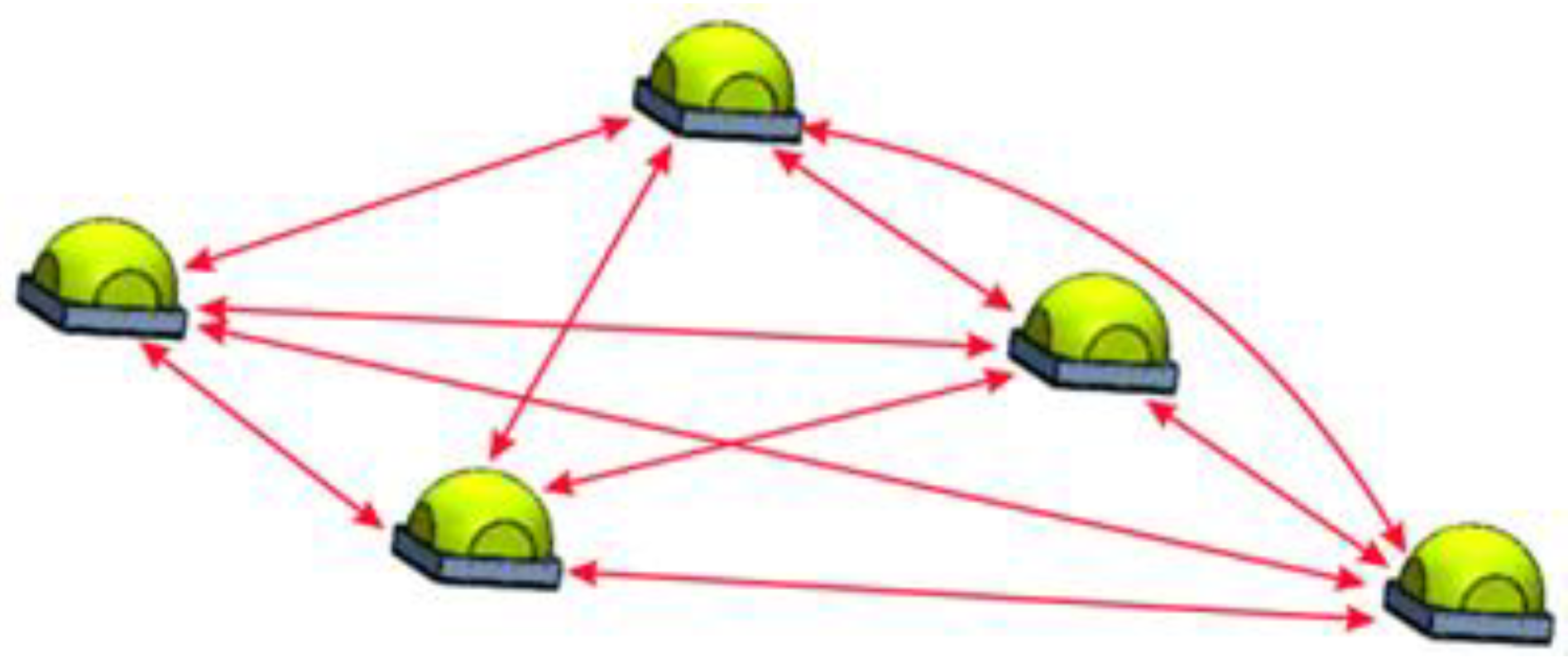
The results presented in the above publications concerned the reduction of the junction temperature Tj using a heat sink system for an assumed heat source (one or multiple LEDs). On the other hand, another equally important factor affecting the junction temperature is the number and arrangement of LEDs on the MCPCB substrate. The mentioned factor is particularly important in the context of high-power luminaires, where a significant number of LEDs are installed in close proximity, between which there are mutual thermal couplings [26]. LEDs operating at a given power Pe, in addition to the phenomenon of self-heating, causing an increase in their own junction temperature Tj by the thermal coupling that occurs (Figure 2), affect the increase in temperature Tj of other light sources installed on the common substrate MCPCB.
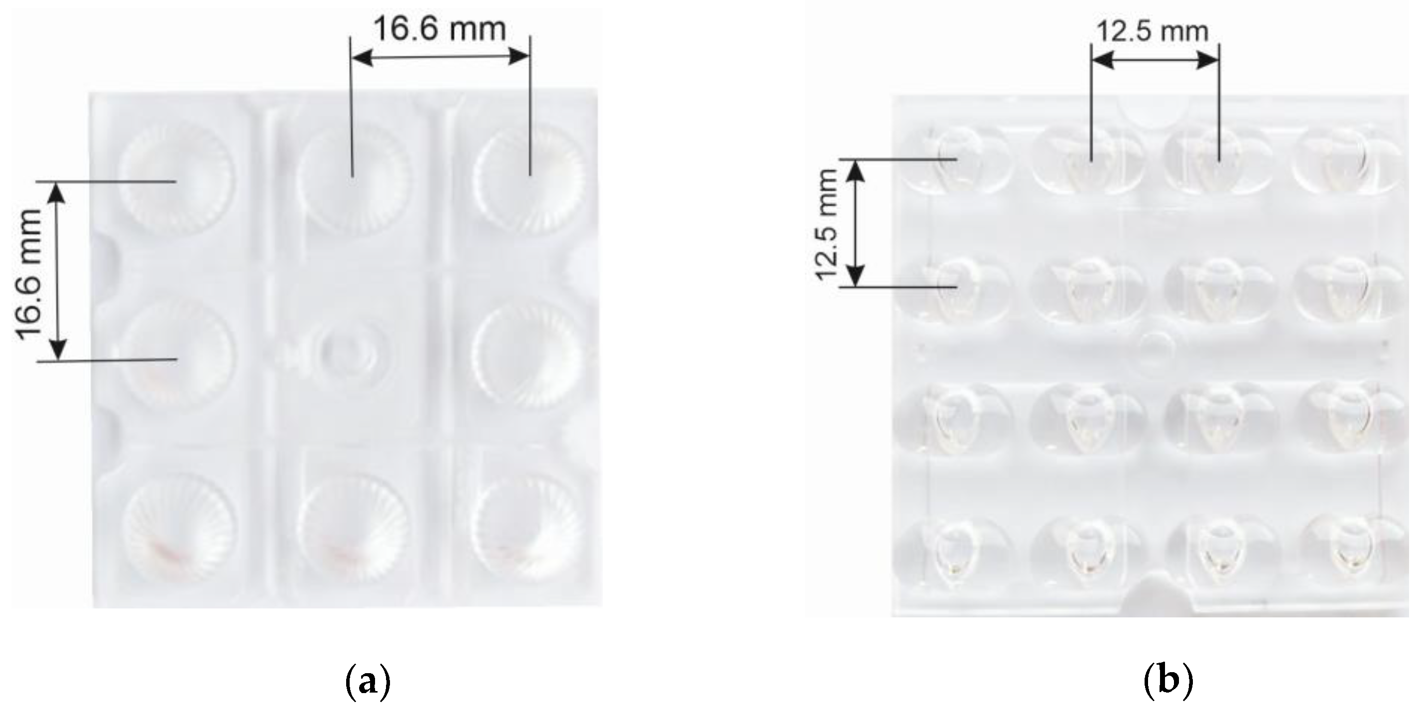
The scale of thermal coupling between LEDs can vary and depends on the power Pe of the individual LEDs, their number and their position relative to each other. In luminaires for illumination, the number of LEDs often depends on the size of the housing and available space in the optical chamber. The distance between LEDs is also determined by the size of the luminaire’s optical chamber and the optical system used to form the luminaire’s light distribution curve. There are many variants of lens systems available on the lighting market, differing in the number and distance between LEDs in the lens array (Figure 3).
Figure 3 shows an example of lens systems where a LED array consists of 8 and 16 LEDs and the distance between adjacent light sources is in the range of 12–16 mm. The most common distances between LED sources in the lens matrix are in the range of 10–30 mm.
In the literature on thermal issues of LEDs, one encounters articles that address issues related to the arrangement of LEDs and their thermal interaction. Article [27] analyzed the effect of the number and thickness of the heat sink fins and the arrangement of LEDs for a LED bulb. A 3D model was prepared and then, using the finite element method, thermal calculations were made for a variable distance of five light sources in a LED bulb. Article [28] presents thermal analysis for a 3.5 W COB module using COMSOL Multiphysics software. This article analyzes the change in the number of LEDs from one to nine and their spacing from 0.5 mm to 3 mm. Simulation results showed that as the distance between the light sources increased, the thermal resistance of the light sources decreased, making it possible to reduce the junction temperature Tj by several percent. Article [29] shows the impact of LED arrangement using a common MCPCB substrate and a separate one for each source. Presented tests for two different MCPCB substrate designs showed that using separate substrates (individual substrate for each LED) improves heat transfer.
This article presents research related to the determination of the influence of thermal couplings between LED sources on their thermal operating conditions and the final junction temperature. The tests were performed for the main factors (number of sources, their distance, the value of forward current) shaping the temperature of LED sources in high-power luminaires, for which the available literature has only a small number of studies that take into account all the above-mentioned factors.
The article presents the results of studies related to the influence of the number of LEDs used, their power and arrangement on the thermal operating conditions and final junction temperature Tj. The above-mentioned issue applies especially to high-power luminaires (luminaires for illumination, road lighting, etc.) where the number of light sources used and the distances between them are limited by the surface area of the body and optical chamber as well as the lens array used. Using FLOEFD CFD software by Siemens, a model of a LED panel was made in which the thermal analysis was performed on variable number of LEDs used, with their number varying from 6 to 36. The studies were conducted for three values of forward current IF and the panel power varied from a few to more than 100 W. For a panel with 36 LEDs installed, the effect of the distance between each light source was analyzed in a range corresponding to the distance of the light sources in most lenticular systems (5–25 mm). The results obtained were analyzed with regard to the influence of the above factors on the thermal operating conditions of LED panels and then final conclusions were made.
2. Thermal Model of the LED Panel
Thermal testing of the LED panel was realized using FLOEFD CFD software by Siemens. The selected tool has, among other things, a built-in CAD module for creating the analyzed three-dimensional geometry and a flow simulation module based on computational fluid dynamics for advanced thermal calculations, taking into account all types of heat transport, i.e., conduction, convection and radiation [30,31].
CFD software is based on solving the Navier-Stokes equations, which are formulations of the laws of conservation of mass, momentum and energy for the flow of fluid [32,33]:
where: u—fluid velocity, —fluid density, Si—mass distributed external force per unit mass due to a porous media resistance, he—thermal enthalpy, QH—heat source or sink per unit volume, —viscous shear stress tensor, qi—diffusive heat flux.
2.1. Model Geometry
The structure of the LED panel used for the simulation study is shown in Figure 4. An aluminum plate measuring 180 × 180 × 5 mm constitutes a heat sink on which a MCPCB substrate with LEDs installed is mounted. High-power LEDs 3.5 × 3.5 mm were selected for the simulation and the determined actual thermal resistance Rthj-c was used to determine the junction temperature [34]. LEDs were attached to the MCPCB with 96.5Sn3.5Ag solder paste and the MCPCB was attached to the heat sink with a thermally conductive paste (TIM). The detailed structure, thickness of each layer and thermal conductivity coefficient for the materials used are summarized in Table 1.
2.2. Boundary Conditions
For the study, it was assumed that the thermal properties of the materials used in the simulations are homogeneous and isotropic. There are no air gaps between the different layers of materials, therefore there is perfect thermal conductivity between the layers. Natural air convection was taken into account in the simulations.
The main equation describing the defined heat exchange is shown below [28]:
where: k—thermal conductivity, —fluid density, T—temperature, P—pressure, Cp—specific heat, —viscous shear stress tensor, qi—diffusive heat flux.
In the steady state, the equation defining the system in three-dimensional Cartesian coordinates is as follows [28]:
Heat power PH of the LEDs defined in the simulation studies was determined experimentally and is presented in publication [11]. Heat power, depending on the assumed forward current IF, ranged from 50 to 63% of the total electrical power Pe. A temperature model based on the value of the thermal resistance between the junction and the housing Rthj-c was used to determine the junction temperature Tj [36,37]. The selected thermal model was defined and presented in the international standard JEDEC JESD15-3 two-resistor compact thermal model guideline [38]. It can be implemented and used in three-dimensional simulation tools, including CFD. The value of the thermal resistance Rthj-c for the LED used in the study was determined experimentally and is presented in publication [II]. The ambient temperature Ta during the study was 25 °C and the air pressure surrounding the panel was P = 101.325 kPa. In the simulation calculations, thermal radiation was taken into account, the emissivity coefficient ℇ for the aluminum panel was 0.2. The calculation assumes a gravitational acceleration of g = 9.81 m/s2, opposite to the direction of the Y axis.
The computational domain with the assumed boundary conditions and the cross-section of the computational grid are shown in Figure 5.
The size of the computation domain was selected based on consideration of heat transfer characteristics and computation time. The height of the domain was assumed as 7Hp, the width and length of the computation domain as 2Wp and 2Lp, where Hp, Wp and Lp stand for the height, width and length of the LED panel, respectively.
The computation grid was defined using the FloEFD 2021.3 software’s built-in advanced module for creating an adaptive numerical grid.
3. Results and Discussion
Simulation studies for the LED panel model presented in the second chapter were conducted for two variants: the first, in which the number of thermally coupled LEDs was changed, and the second, in which the distance between adjacent LEDs was changed. Tests of both variants were realized for three values of forward current IF of LEDs: 350, 700 and 1050 mA, which determined the electrical power of a single LED of 1, 2.1 and 3.3 W, respectively. The impact of the above factors was analyzed regarding the thermal operating conditions of LEDs.
Figure 6 shows the main variables of thermal analysis of the LED panel.
3.1. The Impact of the Number of Thermally Coupled LEDs
A view of all variants related to the variable number of LEDs installed is shown in Figure 7. The number of LEDs on the panel varied from 6 to 36, in increments of 6. A panel containing 6 LEDs was marked 6 × 1, a panel containing 12 light sources was marked 6 × 2, and so on. The distance between adjacent light sources was fixed at d = 20 mm.
The resulting temperature distribution for an example 6 × 1 LED panel and forward current IF = 700 mA is illustrated in Figure 8.
The maximum junction temperature Tj for this LED panel was determined for the middle light sources and was Tj = 49.75 °C (Figure 7). In the case of extreme light sources, this temperature was 0.2 °C lower. The temperature of the aluminum plate constituting a heat sink was characterized by a uniform distribution. On average, it was about 36 °C.
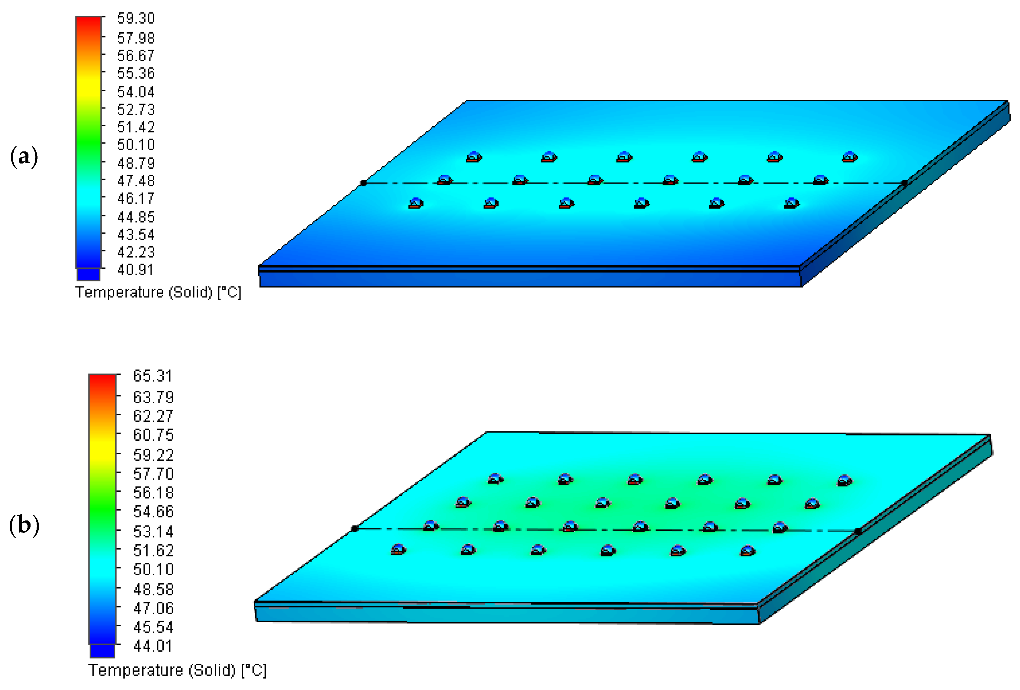
Temperature distribution for the 3 × 6 and 4 × 6 LED panel at forward current IF = 700 mA is shown in Figure 9.
For the 3 × 6 panel, the maximum junction temperature Tj for a LED located in the center of the panel was Tj = 59.30 °C, while increasing the number of LEDs to 4 × 6 resulted in an increase in the maximum temperature Tj of the central light source to a value of 65.31 °C, which was an increase of about 10%. The dotted line (Figure 8) marks the axis of determination of the temperature distribution along the length of the LED panel, where the highest temperatures Tj of the installed LEDs occur. Temperature distribution of the tested LED panels along the axis discussed above is shown in Figure 10 and Figure 11. The maximum LED source junction temperature for all panel configurations with a different number of sources is summarized in Table 2.
An increase in the value of the forward current IF, and thus also an increase in the electrical power Pe and the resulting heat power PH, resulted in an increase in the junction temperature Tj of the individual light sources. For the 1 × 6 panel, an increase in the forward current IF from 350 to 700 mA resulted in an increase in the junction temperature Tj from 35 to 50 °C (an increase in Tj of about 43%). A further increase of IF from 700 to 1050 mA resulted in an increase in the temperature Tj from 50 to 61 °C, which was an increase of 22% compared to current IF = 700 mA and 74% compared to IF = 350 mA. For 3 × 6, 5 × 6 and 6 × 6 panels, an increase in IF current values resulted in correspondingly higher and higher increases in the temperature Tj, which is related to the higher number of LEDs installed on a common heat sink and the occurrence of thermal couplings between them.
The largest increase in the junction temperature Tj was obtained for the 6 × 6 LED panel, where an increase in the forward current IF from 350 to 700 mA resulted in an increase in the junction temperature Tj of the central LED from 47 °C to 76 °C, which was an increase of 62%. A further increase of IF from 700 to 1050 mA resulted in another increase in the temperature Tj to 108 °C, which was an increase of 42% compared to IF = 700 mA and 130% compared to IF = 350 mA.
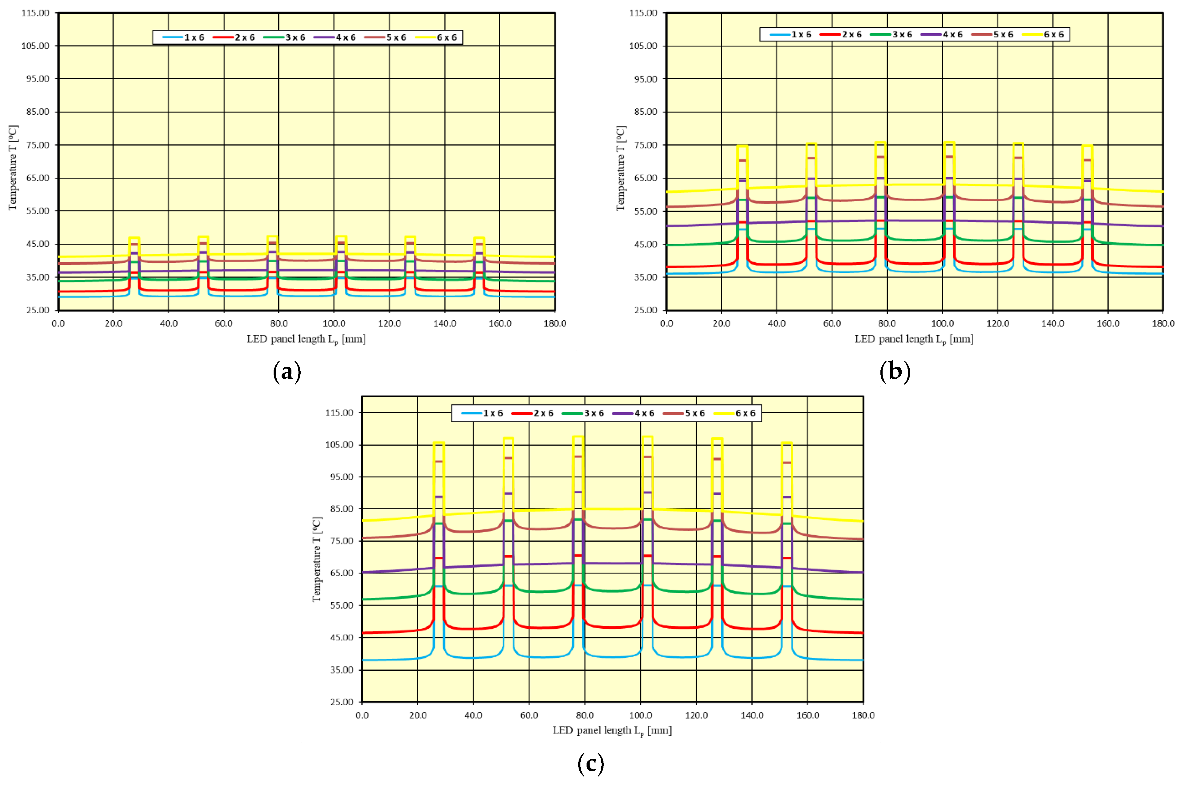
Figure 10 shows the temperature distribution of the tested LED panels, along the axis with the maximum temperature Tj of the installed LED sources for three values of forward current IF. Increasing the number of LEDs installed on a common heat sink resulted in an increase in the junction temperature Tj of the light sources, which is related to thermal coupling and thermal interaction between the individual light sources.
Increasing the total number of light sources by another six resulted in an increase in the junction temperature Tj, with the increase depending on the value of the forward current IF. The smallest average increase in the junction temperature Tj was recorded for current IF = 350 mA, where the addition of another row with six LEDs resulted in an average increase in the junction temperature Tj of about 2.5 °C (6%). For current IF = 700 mA, the average increase in temperature Tj was about 5.2 °C (9%), while for current IF = 1050 mA, the average increase was about 9.3 °C (12%). The smallest increase in temperature Tj for current IF = 350 and 700 mA was recorded for changing the configuration of installed solid-state light sources from 1 × 6 to 2 × 6, while the largest increase in temperature Tj for all IF current values was determined for changing the number of installed LEDs from 2 × 6 to 3 × 6.
The highest increase in temperature Tj for the 3 × 6 configuration was associated with the formation of a central row of LEDs, in which the installed light sources thermally interact on each side, with surrounding neighboring sources. In the case of the 2 × 6 configuration, the installed LEDs on one side do not thermally interact with other sources, which affects the lower value of the junction temperature Tj of the installed solid-state light sources.
3.2. The Impact of the Distance between LEDs
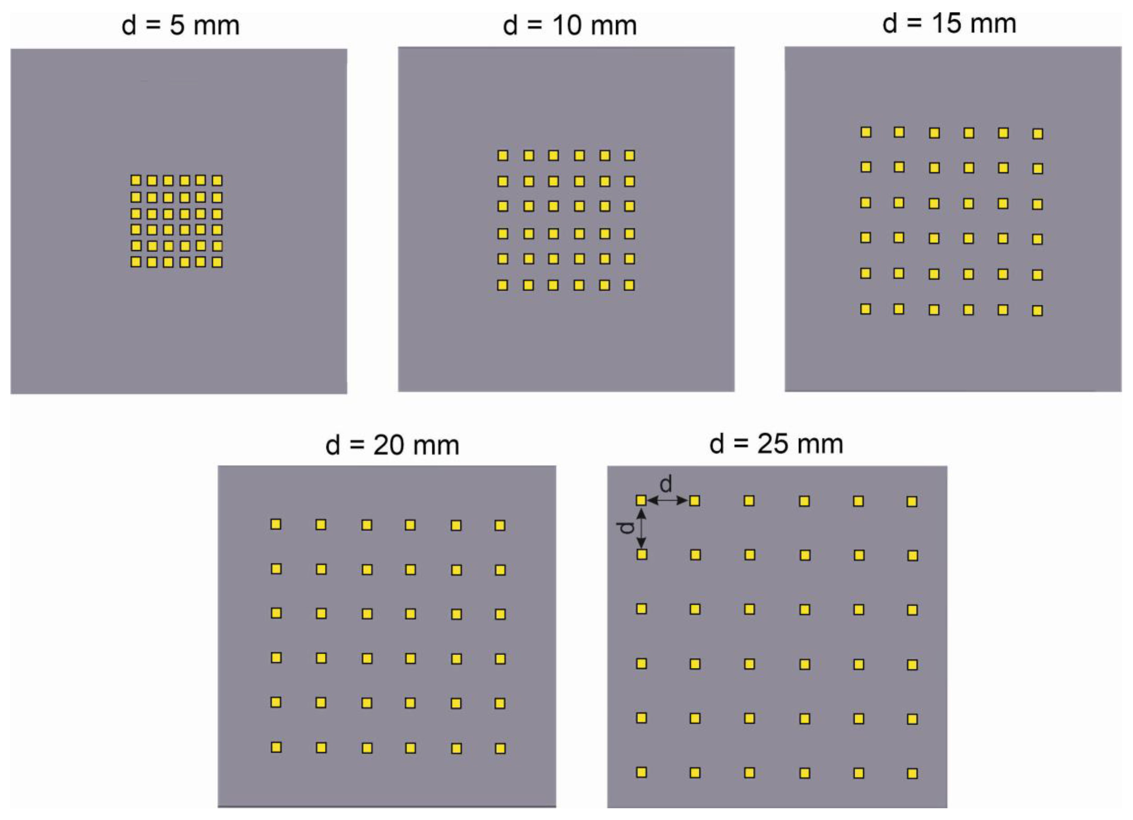
The study of the impact of the distance between the installed LEDs was realized for a LED panel with 36 LEDs installed (6 × 6). The distance between the installed LEDs was changed in the range of 5–25 mm and took the following values, respectively: 5; 10; 15; 20 and 25 mm (Figure 12).
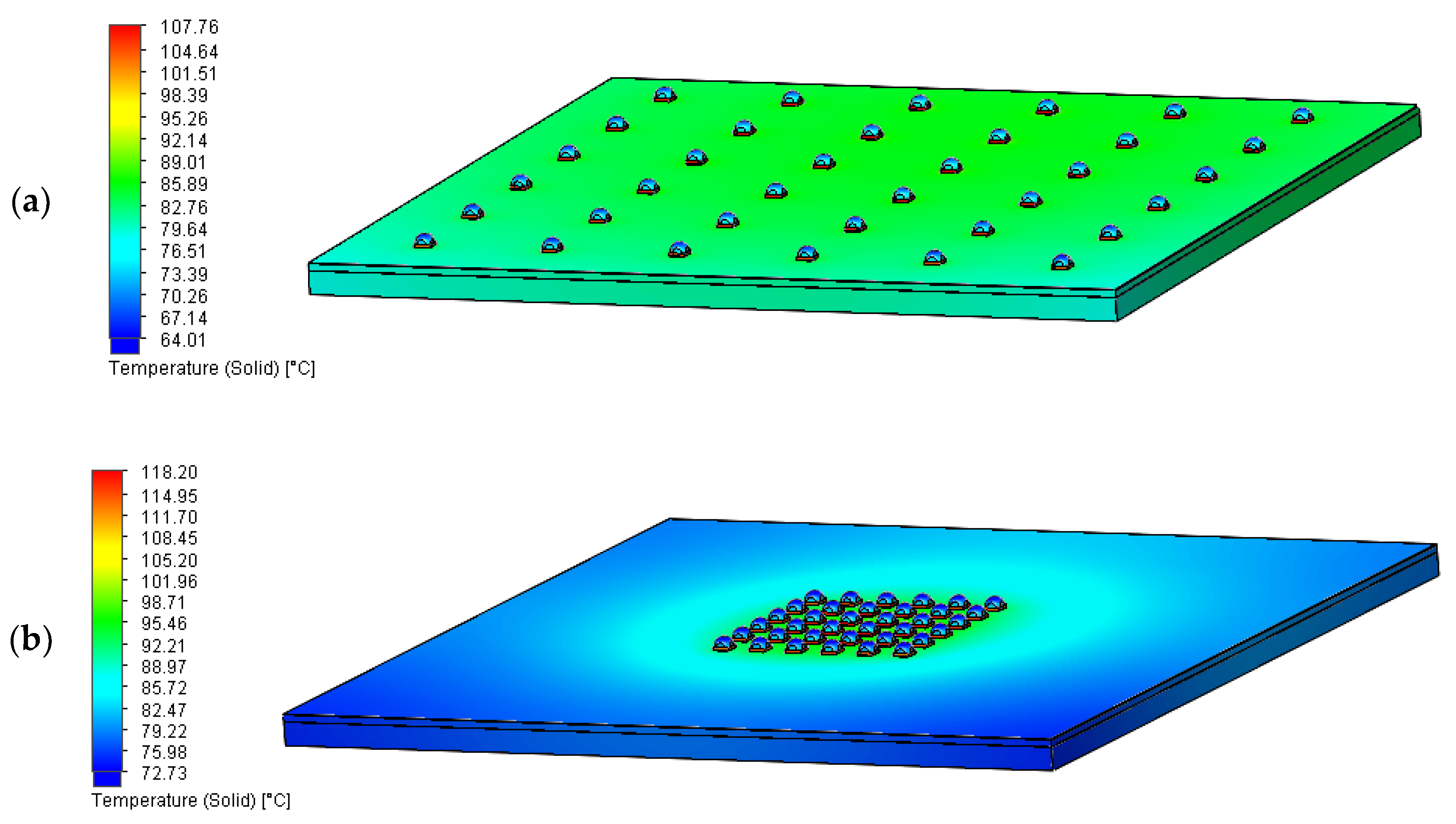
Figure 13 shows the temperature distribution of the 6 × 6 LED panel for the two extreme distances between the installed LEDs of d = 25 and 5 mm, respectively, and for a maximum forward current value of IF = 1050 mA. For a panel where the distance between the installed solid-state light sources was d = 25 mm, an even temperature distribution was obtained over the entire panel surface, while the determined maximum temperature Tj of a junction located in the center of the panel reached a value above 107 °C. For an analogous panel, where the distance between LEDs was reduced to d = 5 mm, the maximum junction temperature Tj of the light source located in the center of the panel was Tj = 118.2 °C.
Temperature distribution of the LED panel along the axis with the maximum junction temperature Tj of the installed LED sources for three values of forward current IF is shown in Figure 14.
Table 3 summarizes the maximum junction temperature of the LED sources for all tested distances between the LED sources.
For forward current IF = 350 mA, changing the distance d between the installed light sources from 5 to 25 mm had little effect on the increase in the value of the junction temperature Tj. The largest increase in the maximum temperature Tj was determined for d = 5 mm. It amounted to about 5% compared to a distance of d = 25 mm. For a distance between the sources of d = 10 mm, the increase in temperature Tj was about 3%, while for distances of d = 15 mm and d = 20 mm the increase was virtually imperceptible.
For forward current IF = 700 mA and IF = 1050 mA, a greater effect of changing the distance d between installed LEDs on the temperature Tj was observed, compared to forward current IF = 350 mA. For a distance between LEDs of d = 5 mm, an increase in the maximum junction temperature Tj of the centrally installed LED was 9% for IF = 700 mA and 10% for IF = 1050 mA, compared to a distance of d = 25 mm. For a distance of d = 10 mm, an increase in the temperature Tj was about 5% for both IF values, while for distances of 15 and 20 mm, the increase did not exceed 3%.
4. Conclusions
Thermal operating conditions of LEDs have a significant impact on the obtained values of luminous-electrical parameters, as well as on the service life of solid-state light sources. To reduce the junction temperature Tj, cooling systems are used to ensure optimal operating conditions for light sources. The junction temperature Tj of solid-state light sources, thermally coupled to each other on a common heat sink, depends on the electrical power Pe and the resulting heat power PH, on the number of LEDs installed and the distance d between them. The effect of the above-mentioned factors on the thermal operating conditions of a LED panel was determined on the basis of the simulation studies presented.
The junction temperature Tj of the panel LEDs also depends on the number of coupled light sources and the distance between them, as shown by the research results presented in the article.
The issues presented above and the impact of the above-mentioned factors on the value of the junction temperature Tj of LEDs apply especially to high-power luminaires (including illumination or road lighting), where a large number of solid-state light sources are thermally coupled in close proximity to each other. The number of LEDs, which depends on the available space in the optical chamber, the selection of the appropriate value of the forward current IF to achieve the final power and parameters of the luminaire, as well as the arrangement of the light sources, often dependent on the lenticular systems used, affect the thermal operating conditions of LEDs, as presented in this article.
Thus, in view of the necessity to use high-powered luminaires for flood illumination, the proper direction of light-optical system design work is to pursue the use of a larger number of individual LEDs in a luminaire. This allows for a reduction of the value of the forward current IF and ultimately reduction of the junction temperature Tj. The second key factor in improving thermal conditions in luminaires for illumination is the design of the geometry of lenticular optical systems, allowing the necessary, according to the needs, distance between individual LEDs. The two mentioned design factors lead to a final conclusion of general nature, indicating the necessity of using larger-sized bodies in high-power luminaires for illumination, allowing the appropriate selection of a lenticular optical system and proper arrangement of LEDs.
According to the authors of the publication, the obtained results indicate the need for designers of lens optical systems to take into account the need to construct optical arrays with different distances for positioning LED sources. Current design practice involves a small range of variations in distance between individual sources. The possibility of using a lens system with an increased distance between the sources reduces the junction temperature. An important issue for designers of lighting luminaires is the selection of the optimal number of LED sources and their forward current IF. The obtained test results show a strong influence of the above-mentioned parameters on the temperature operating conditions of the luminaire sources. The above parameters depend on the available space in the optical chamber of the luminaire, therefore it is advisable that designers use optimization models that permit the definition of the optimal number and forward current IF of sources that minimize the temperature operating conditions of the light sources for specific lighting luminaire design solutions.
The research results available in the article confirm the validity of using computer-based computational tools to design and evaluate the thermal operating conditions of solid-state light sources. The reliability of the obtained simulation results relating to thermal modeling of solid-state light sources was confirmed in article [11], where verifying real measurements were made for an analogous thermal model of a LED panel.
Reducing electricity consumption, both in outdoor lighting and indoor lighting, is a challenge for lighting systems. The current energy situation in Europe and in the world requires minimizing energy consumption costs. For this purpose, measures are taken and systems are designed to reduce energy consumption and reduce CO2 emissions to the atmosphere. One example of these solutions, given here, is based on a decentralized street lighting control strategy for the optimal planning of energy modernization of the street lighting system [39]. Another example is the use of daylight to reduce energy consumption in interior lighting [40]. Lighting systems that enable the reduction of energy consumption and the reduction of CO2 emissions, while ensuring factors related to visual comfort (appropriate level of lighting intensity, uniformity of lighting, glare reduction) or ecological factors (reduction of light pollution) are currently a challenge for designers of luminaires and lighting systems. Taking into account the thermal conditions presented in the article and limiting the junction temperature of the LED sources also affects the above factors (lowering the junction temperature affects the higher efficiency of light sources and luminaires and their longer service life). It seems reasonable that future research work and challenges in the design of lighting luminaires should include the definition of optimization models as decision support systems enabling the maximum reduction of the junction temperature of the designed LED luminaires.
Author Contributions
Conceptualization, A.R., H.W. and K.B.; methodology, K.B., H.W. and M.L.; software, K.B. and M.L.; validation, S.R., K.B., H.W. and M.L.; formal analysis, H.W.; investigation, H.W. and K.B.; resources, A.R. and H.W.; data curation, A.R., H.W.; writing—original draft preparation, K.B.; writing—review and editing, S.R. and M.L.; supervision, A.R., H.W. and S.R. All authors have read and agreed to the published version of the manuscript.
Funding
This research received no external funding.
Conflicts of Interest
The authors declare no conflict of interest.
Nomenclature
| ℇ | emissivity factor |
| ηo | optical efficiency |
| u | fluid velocity |
| flud density | |
| τik | viscous shear stress tensor |
| Φ | luminous flux |
| CFD | computational fluid dynamics |
| CCT | correlated color temperature |
| Cp | specific heat |
| CRI | color rendering index |
| d | distance between LED sources |
| g | gravitational acceleration |
| he | thermal enthalpy |
| Hp | LED panel height |
| IF | forward current |
| k | thermal conductivity |
| LED | light emitting diode |
| Lp | LED panel length |
| MCPCB | metal core printed circuit board |
| P | pressure |
| Pe | electrical power |
| PH | heat power |
| Po | optical power |
| QH | heat source or sink per unit volume |
| qi | diffusive heat flux |
| Rthj-c | LED thermal resistance junction to case |
| Si | mass distributed |
| T | temperature |
| Ta | ambient temperature |
| Tj | junction temperature |
| Wp | LED panel width |
References
- LED Source SAW0L60A, Seoul Semiconductor. Available online: http://www.seoulsemicon.com/en/product/spec/SAW0L60A/19 (accessed on 3 September 2022).
- Schubert, F. Light-Emitting Diode, 2nd ed.; Cambridge University Press: Cambridge, UK, 2006. [Google Scholar]
- Jagerbrand, A. LED (Light-Emitting Diode) Road Lighting in Practice: An Evaluation of Compliance with Regulations and Improvements for Further Energy Savings. Energies 2016, 9, 357. [Google Scholar] [CrossRef] [Green Version]
- Lasance, C.; Poppe, A. Thermal Management for LED Applications; Springer: New York, NY, USA, 2014. [Google Scholar]
- Acuna, P.; Leyre, J.; Audenaert, J.; Meuret, Y.; Deconinck, G.; Hanselaer, P. Impact of geometrical and optical parameters on the performance of a cylindrical remote phosphor LED. IEEE Photonics J. 2015, 7, 1601014. [Google Scholar] [CrossRef] [Green Version]
- Wachta, H.; Baran, K.; Leśko, M. The meaning of qualitative reflective features of the facade in the design of illumination of architectural objects. AIP Conf. Proc. 2019, 2078, 020102. [Google Scholar]
- Liu, S.; Luo, X. LED Packaging for Lighting Applications. Design, Manufacturing and Testing; John Wiley & Sons: Singapore, 2011. [Google Scholar]
- Czyżewski, D. Comparison of luminance distribution on the lighting surface of power LEDs. Photonics Lett. Pol. 2019, 11, 118–120. [Google Scholar] [CrossRef]
- Huaiyu, Y.; Kohl, S.; Zeijl, H.; Gielen, A. A review of passive thermal management of LED module. J. Semicond. 2011, 32, 014008-1–014008-4. [Google Scholar]
- Poppe, A.; Lasence, C. On the standardization of thermal characterization of LEDs. In Proceedings of the 25th Annual IEEE Semiconductor Thermal Measurement and Management Symposium, San Jose, CA, USA, 15–19 March 2009; pp. 151–158. [Google Scholar]
- Baran, K.; Różowicz, A.; Wachta, H.; Różowicz, S. Modeling of Selected Lighting Parameters of LED Panel. Energies 2020, 13, 3583. [Google Scholar] [CrossRef]
- Nadarajah, N.; Yimin, G. Life of LED-Based White Light Sources. J. Disp. Technol. 2005, 1, 167–171. [Google Scholar]
- Yurtseven, M.B.; Mete, S.; Onaygil, S. The effects of temperature and driving current on the key parameters of commercially available high-power white LEDs. Light. Res. Technol. 2016, 48, 943–965. [Google Scholar] [CrossRef]
- Tabaka, P.; Rozga, P. The light color quality of LEDs operating at winter temperatures. Photonics Lett. Pol. 2019, 11, 112–114. [Google Scholar] [CrossRef]
- LED Cree Xlamp XP-G2. Available online: http://www.cree.com/led-components/media/documents/XLampXPG2.pdf (accessed on 5 September 2022).
- LED Lumileds Luxeon T. Available online: http://www.lumileds.com/uploads/382/DS106-pdf (accessed on 12 September 2022).
- Hyunjong, K.; Kyoung, J.; Yeonwon, L. Thermal Performance of Smart Heat Sinks for Cooling High Power LED Modules. In Proceedings of the 13th IEEE Intersociety Conference on Thermal and Thermomechanical Phenomena in Electronic Systems, San Diego, CA, USA, 30 May–1 June 2012. [Google Scholar]
- Gupta, D.; Venkataraman, V.; Nimje, R. CFD& Thermal Analysis of Heat Sink and its Application in CPU. Int. J. Emerg. Technol. Adv. Eng. 2014, 4, 198–202. [Google Scholar]
- Min, W.; Seung, W.; Yongchan, K. Optimal thermal design of a horizontal fin heat sink with a modified-opening model mounted on an LED module. Appl. Therm. Eng. 2015, 91, 105–115. [Google Scholar]
- Prem, K.; Gopinath, S.; Debartha, C.; Sameer, K. Copper wick based loop heat pipe for thermal management of a high-power LED module. Appl. Therm. Eng. 2022, 211, 118459. [Google Scholar]
- Yuan, J.; Hongming, F.; Wei, W. Investigation of a novel natural convection heat sink for LEDs based on U-shaped mini-heat pipe arrays. Appl. Therm. Eng. 2022, 204, 118000. [Google Scholar]
- Huang, D.; Chen, T.; Tsai, L.; Lin, M. Design of fins with a grooved heat pipe for dissipation of heat from high powered automotive LED headlights. Appl. Therm. Eng. 2019, 180, 550–558. [Google Scholar] [CrossRef]
- Chengdi, X.; Hailong, L.; Yan, W.; Junhui, L.; Wenhui, Z. A novel automated heat-pipe cooling device for high-power LEDs. Appl. Therm. Eng. 2017, 111, 1320–1329. [Google Scholar]
- Lin, X.; Mo, S.; Mo, B.; Jia, L.; Chen, Y.; Cheng, Z. Thermal management of high-power LED based on thermoelectric cooler and nanofluid-cooled microchannel heat sink. Appl. Therm. Eng. 2020, 172, 115165. [Google Scholar] [CrossRef]
- Ahlem, B.; Zouhour, A.; Laurent, C.; Kamel, C.; Georges, Z. Energy efficiency of a LED lighting system using a Peltier module thermal converter. Case Stud. Therm. Eng. 2022, 134, 101989. [Google Scholar] [CrossRef]
- Górecki, K. The influence of mutual thermal interactions between power LEDs on their characteristics. In Proceedings of the 19th International Workshop on Thermal Investigations of ICs and Systems Therminic, Berlin, Germany, 25–27 September 2013; pp. 188–193. [Google Scholar]
- Gong, Y.; Zhu, Z. Impact of the LED chips placement and heat sink design on the multi-chip LED bump performance. In Proceedings of the 15th International Conference on Electronic Packaging Technology, Chengdu, China, 12–15 August 2014; pp. 28–31. [Google Scholar]
- Abdelmlek, K.; Araoud, Z.; Charrada, K.; Zissis, G. Optimization of the thermal distribution of multi-chip LED package. Appl. Therm. Eng. 2017, 126, 653–660. [Google Scholar] [CrossRef]
- Abdelmlek, K.; Araoud, Z.; Canele, L.; Charrada, K.; Zissis, G. Optimal substrate design for thermal management of high power multi-chip LEDs module. Optik 2021, 242, 167179. [Google Scholar] [CrossRef]
- Della Torre, A.; Motenegro, G.; Onorati, A.; Khadilkar, S.; Icarelli, R. Multi-Scale CFD Modeling of Plate Heat Exchangers Including O set-Strip Fins and Dimple-Type Turbulators for Automotive Applications. Energies 2019, 12, 2965. [Google Scholar] [CrossRef] [Green Version]
- Chein, R.; Chen, J. Numerical study of the inlet/outlet arrangement effect on microchannel heat sink performance. Int. J. Ther. Sci. 2009, 48, 1627–1638. [Google Scholar] [CrossRef]
- Andersson, B.; Andersson, R.; Hakansson, L.; Mortensen, M.; Sudiyo, R.; Wachem, B. Computational Fluid Dynamics for Engineers; Cambridge University Press: Edinburgh, UK, 2012. [Google Scholar]
- FloEFD. Technical Reference, Software Version 16; Mentor Graphics Corporation: Wilsonville, OR, USA, 2016. [Google Scholar]
- Baran, K.; Różowicz, A.; Wachta, H.; Różowicz, S.; Mazur, D. Thermal analysis of the factors influencing junction temperature of LED panel sources. Energies 2019, 12, 3941. [Google Scholar] [CrossRef] [Green Version]
- FloEFD Engineering Database. Available online: https://www.mentor.com/products/mechanical/floefd/ (accessed on 12 September 2022).
- Baran, K.; Wachta, H.; Leśko, M.; Różowicz, A. Research on thermal resistance Rthj-c of high powersemiconductor light sources. In Proceedings of the 15th Conference on Computational Technologies in Engineering, AIP Conference Proceedings 2078, Mikolajki, Poland, 16–19 October 2018; p. 020047. [Google Scholar]
- Poppe, A. Simulation of LED based luminaires by using multi-domain compact models of LEDs and compact thermal models of their thermal environment. Microelectron. Reliab. 2017, 72, 65–74. [Google Scholar] [CrossRef]
- JEDEC STANDARD. Two-Resistor Compact Thermal Model Guideline; JESD15-3; JEDEC Solid State Technology Association: Arlington, VA, USA, 2008. [Google Scholar]
- Carli, R.; Dotoli, M. A Dynamic Programming Approach for theDecentralized Control of Energy Retrofit in Large-Scale Street Lighting Systems. IEEE Trans. Autom. Eng. 2020, 17, 1140–1157. [Google Scholar]
- Bonomolo, M.; Baglivo, C.; Bianco, G.; Congedo, P.; Beccali, M. Cost optimal analysis of lighting retrofit scenarios in educational buildings in Italy. Energy Procedia 2017, 126, 171–178. [Google Scholar] [CrossRef]
Figure 1.
Multi-source high-power LED luminaires: (a) floodlight and (b) street luminaire.

Figure 2.
Thermal mutual coupling between LEDs.

Figure 3.
An example of multi-lens array systems with different distances between adjacent LEDs: (a) 16.6 mm, (b) 12.5 mm.
Figure 3.
An example of multi-lens array systems with different distances between adjacent LEDs: (a) 16.6 mm, (b) 12.5 mm.

Figure 4.
Structure of an example LED panel (2 × 6 LEDs).

Figure 5.
Simulation model of the LED panel: (a) computation domain with the assumed boundary conditions and (b) cross-section of the computation grid along the XYZ axis.
Figure 5.
Simulation model of the LED panel: (a) computation domain with the assumed boundary conditions and (b) cross-section of the computation grid along the XYZ axis.

Figure 6.
Graphical representation of the variable parameters of the thermal analysis of the LED panel.
Figure 6.
Graphical representation of the variable parameters of the thermal analysis of the LED panel.

Figure 7.
Tested LED panel variants associated with variable number of installed LEDs.

Figure 8.
6 × 1 LED panel, IF = 700 mA: (a) temperature distribution for the tested panel, (b) determined junction temperature Tj of individual LEDs.
Figure 8.
6 × 1 LED panel, IF = 700 mA: (a) temperature distribution for the tested panel, (b) determined junction temperature Tj of individual LEDs.


Figure 9.
Temperature distribution of the LED panel at IF = 700 mA: (a) 3 × 6, (b) 4 × 6.

Figure 10.
Temperature distribution for selected panels and three values of IF current along the axis with the maximum temperature Tj of LEDs: (a) 1 × 6, (b) 3 × 6, (c) 5 × 6, (d) 6 × 6.
Figure 10.
Temperature distribution for selected panels and three values of IF current along the axis with the maximum temperature Tj of LEDs: (a) 1 × 6, (b) 3 × 6, (c) 5 × 6, (d) 6 × 6.

Figure 11.
Temperature distribution of LED panels along the axis with the maximum temperature Tj of installed LEDs for different panel configurations: (a) IF = 350 mA, (b) IF = 700 mA, (c) IF = 1050 mA.
Figure 11.
Temperature distribution of LED panels along the axis with the maximum temperature Tj of installed LEDs for different panel configurations: (a) IF = 350 mA, (b) IF = 700 mA, (c) IF = 1050 mA.

Figure 12.
6 × 6 LED panel with variable distance d between installed LEDs.

Figure 13.
Temperature distribution of the LED panel at IF = 1050 mA: (a) d = 25 mm, (b) d = 5 mm.

Figure 14.
Temperature distribution of LED panels along the axis with the maximum temperature Tj of installed LEDs for different distance between them: (a) IF = 350 mA, (b) IF = 700 mA, (c) IF = 1050 mA.
Figure 14.
Temperature distribution of LED panels along the axis with the maximum temperature Tj of installed LEDs for different distance between them: (a) IF = 350 mA, (b) IF = 700 mA, (c) IF = 1050 mA.


Table 1.
LED panel—materials and their thermal parameters [35].
Table 1.
LED panel—materials and their thermal parameters [35].
| Layer | Material | Thickness (mm) | Thermal Conductivity k (W/m·K) | Thermal Resistance Rthj-c (°C/W) |
|---|---|---|---|---|
| Heat sink | Aluminum 5052 | 5 | 140 | - |
| TIM | Thermal grease | 0.1 | 3 | - |
| MCPCB | Cu | 0.035 | 400 | |
| Dielectric | 0.1 | 2 | - | |
| Aluminum 5052 | 1.5 | 140 | ||
| Soldering | 96.5Sn3.5Ag | 0.1 | 33 | |
| LED | - | - | - | 8.6 IF = 350 mA |
| 8.6 IF = 700 mA | ||||
| 8.8 IF = 1050 mA | ||||
| Lens | Epoxy resin | - | 0.2 | - |
Table 2.
The maximum temperature of the LED source junction for a panel with a variable number of sources.
Table 2.
The maximum temperature of the LED source junction for a panel with a variable number of sources.
| Number of LED Panel Sources | Distance between LED Sources d (mm) | Current IF (mA) | Maximum Junction Temperature Tj (°C) |
|---|---|---|---|
| 1 × 6 | 20 | 350 | 34.72 |
| 2 × 6 | 36.62 | ||
| 3 × 6 | 39.90 | ||
| 4 × 6 | 42.62 | ||
| 5 × 6 | 45.45 | ||
| 6 × 6 | 47.44 | ||
| 1 × 6 | 20 | 700 | 49.75 |
| 2 × 6 | 52.19 | ||
| 3 × 6 | 59.30 | ||
| 4 × 6 | 65.31 | ||
| 5 × 6 | 71.52 | ||
| 6 × 6 | 75.92 | ||
| 1 × 6 | 20 | 1050 | 61.25 |
| 2 × 6 | 70.51 | ||
| 3 × 6 | 81.74 | ||
| 4 × 6 | 90.21 | ||
| 5 × 6 | 101.32 | ||
| 6 × 6 | 107.60 |
Table 3.
Maximum junction temperature for a panel with variable distance between LED sources.
| Number of LED Panel Sources | Distance between LED Sources d (mm) | Current IF (mA) | Maximum Junction Temperature Tj (°C) |
|---|---|---|---|
| 6 × 6 | 5 | 350 | 50.40 |
| 10 | 49.28 | ||
| 15 | 48.46 | ||
| 20 | 47.82 | ||
| 25 | 47.74 | ||
| 6 × 6 | 5 | 700 | 82.65 |
| 10 | 79.85 | ||
| 15 | 78.00 | ||
| 20 | 77.03 | ||
| 25 | 76.11 | ||
| 6 × 6 | 5 | 1050 | 118.20 |
| 10 | 113.40 | ||
| 15 | 110.17 | ||
| 20 | 108.51 | ||
| 25 | 107.76 |
Publisher’s Note: MDPI stays neutral with regard to jurisdictional claims in published maps and institutional affiliations. |
© 2022 by the authors. Licensee MDPI, Basel, Switzerland. This article is an open access article distributed under the terms and conditions of the Creative Commons Attribution (CC BY) license (https://creativecommons.org/licenses/by/4.0/).
Share and Cite
MDPI and ACS Style
Różowicz, A.; Wachta, H.; Baran, K.; Leśko, M.; Różowicz, S. Arrangement of LEDs and Their Impact on Thermal Operating Conditions in High-Power Luminaires. Energies 2022, 15, 8142. https://0-doi-org.brum.beds.ac.uk/10.3390/en15218142
AMA Style
Różowicz A, Wachta H, Baran K, Leśko M, Różowicz S. Arrangement of LEDs and Their Impact on Thermal Operating Conditions in High-Power Luminaires. Energies. 2022; 15(21):8142. https://0-doi-org.brum.beds.ac.uk/10.3390/en15218142
Chicago/Turabian StyleRóżowicz, Antoni, Henryk Wachta, Krzysztof Baran, Marcin Leśko, and Sebastian Różowicz. 2022. "Arrangement of LEDs and Their Impact on Thermal Operating Conditions in High-Power Luminaires" Energies 15, no. 21: 8142. https://0-doi-org.brum.beds.ac.uk/10.3390/en15218142
Note that from the first issue of 2016, this journal uses article numbers instead of page numbers. See further details here.