Article

Theoretical and Experimental Investigation on Comparing the Efficiency of a Single-Piston Valved Linear Compressor and a Symmetrical Dual-Piston Valved Linear Compressor

1
Key Laboratory of Technology on Space Energy Conversion, Technical Institute of Physics and Chemistry, Chinese Academy of Sciences, Beijing 100190, China
2
University of Chinese Academy of Sciences, Beijing 100190, China
*
Authors to whom correspondence should be addressed.
Submission received: 29 October 2022 / Revised: 14 November 2022 / Accepted: 16 November 2022 / Published: 21 November 2022
(This article belongs to the Special Issue Advanced Research on High-Energy Performance Compressors)

Abstract

:
The efficiency of the valved linear compressor is very important to the efficiency of the space J-T throttling refrigerator. To compare the efficiency of the single-piston valved linear compressor (SVLC) and the symmetrical dual-piston valved linear compressor (SDVLC), this paper explores the factors that affect efficiency. Firstly, this paper analyzes the mechanical vibration system of the linear compressor, the result shows that the efficiency is highest when the external force (current) is in phase with the speed. Then the numerical solutions of the current and velocity are obtained. By comparing the variance and same direction rate of the current and velocity between the SVLC and SDVLC, the reason for the difference in efficiency is explained. Subsequently, the performance of the SVLC and SDVLC are tested on the experimental system. The result shows that the current and velocity of the SDVLC are more in phase, and the isentropic efficiency, volume efficiency and motor efficiency of the SDVLC are all higher than that of the SVLC.

1. Introduction

With the continuous development of space exploration, the cryogenic refrigerator for space detectors needs to seek a higher efficiency and lower minimum temperature [1,2,3]. Recently, linear compressors that provide a pressure ratio and mass flow for space cryogenic refrigerators have been studied. The linear compressor adopts the flexure spring support and gap sealing technology, which reduces the friction loss on the piston. Therefore, the mechanical efficiency of the compressor is improved, which is 20% higher than the overall efficiency of the traditional piston compressors [4].
The linear compressor can be divided into the valved linear compressor and the valveless linear compressor, which are respectively applied to different space refrigerator systems. Generally, valveless linear compressors are commonly applied to pulse tube refrigerators and Stirling refrigerators, while valved linear compressors are applied Joule–Thomson (J-T) throttling refrigerators [5,6,7,8]. Compared with the valveless linear compressors, valved linear compressors can establish a higher pressure ratio which is currently the research hotspot.
As an important moving and energy-consuming component of the cryocooler, the valved linear compressor affects the cooling capacity and efficiency of the refrigerator [9,10,11]. Consequently, it is extremely crucial to improve the efficiency of the valved linear compressor. Some scholars have made different explorations for the improvement of efficiency.
Firstly, the volume efficiency of the valved linear compressors could be improved by reducing the clearance volume. Hanying J et al. discovered that when the clearance is reduced from 0.8 mm to 0.6 mm, an averaged 4% increase in the experimental volumetric efficiency was achieved [12]. However, this method could cause the risk of the piston hitting the cylinder and make the assembly process more difficult.
When the piston of the linear compressor moves at full stroke, the offset will cause the pressure ratio, mass flow and motor efficiency to decrease [13]. Therefore, controlling the piston offset is also an approach to improve efficiency. Liang et al. [14,15] showed the methods of controlling the piston offset, which is increasing the stiffness ratio of the mechanical to gas springs, superimposing a DC voltage to limit the motion of the piston, and control of the pressure in the cylinder. Zou et al. [16] investigated the operating characteristics of the compressor under a different spring stiffness. It can be found that the spring stiffness had a significant impact on the compressor performance. Chen et al. illustrated that increasing the DC voltage can countervail the moving offset [17]. Nevertheless, the DC offset control method brings about an additional electrical power loss and extra Joule heat on the coil. Qi H et al. connected the suction line to the compressor shell which increases the compressor chamber pressure and reduces the pressure difference, to reduce the offset [18]. The approach could improve the motor efficiency, but will reduce the pressure ratio, in practice. In essence, the symmetrical dual-piston structure can minimize or even offset its own vibration [19]. Jian S et al. [20] describes that the dual piston system can significantly reduce the piston offset, in which the motor efficiency and volume efficiency are 87.9% and 79.1%. There is still insufficient research on the comparison of the efficiency between SVLCs and SDVLCs. Based on theory and experiment, this paper shows the difference in the volumetric efficiency, motor efficiency and isentropic efficiency in the valved linear compressors with different piston structures, respectively.

2. Structure and Working Principle of the Valved Linear Compressors

Figure 1 indicates the compositions of a SVLC and a SDVLC, respectively. They both include linear motors, flexure springs, cylinders, pistons, suction valves and discharge valves, etc. The linear motor is a moving coil structure, flexure springs support the coil and the piston to ensure the coaxiality of the cylinder. The discharge valves and the suction valves are arranged on the cylinders and the pistons. The reciprocating linear motor drives the piston to move in the cylinder and complete the compression and expansion process.
The difference between the two structures is that a coil drives a piston of the SVLC, and a coil drives two pistons of a dual-piston linear compressor. Two compression processes could be completed in one cycle of a dual-piston linear compressor, but that is only once of the SVLC.
The piston of the SDVLC reciprocates under the drive of the linear motor. The compression, discharge, expansion and suction processes are carried out, sequentially, in the cylinder. The suction valve and the discharge valve control the gas in and out of the cylinder. The working process illustration with the displacement direction is shown in Table 1. Due to the lack of one piston, the SVLC has a simpler working process than the SDVLC, and the gas is only compressed, discharged, expanded and suctioned in one cylinder.

3. Theoretical Research on the Current and Velocity Characteristics

In addition to the gas force, the piston is subjected to an electromagnetic force during its motion. Due to the presence of friction losses, the system is mechanically damped. At the same time, the flexure springs also provide a reactive force during the motion of the piston. The gas force could be equivalent to a gas spring force, a gas damping and a static force. It should be noted that the static force does not exist in a SDVLC. Therefore, the whole linear compressor could be regarded as a single degree of freedom, damped forced vibration system [21]. The dynamics of the linear compressor are modelled as Figure 2.
When the electromagnetic force F e = F 0 sin ω t , its kinetic equation is:
m x ¨ + c x ˙ + k x = F 0 sin ω t
Substitute the initial conditions: x 0 = 0 ,     x o ˙ = 0 . Following the calculation, we could obtain the displacement:
x = e ω n ξ t C 1 cos ω d t + C 2 sin ω d t + X sin ω t ψ
Obviously, the first term on the right side of the equation is the decay term, and the displacement response at the steady state is:
x = X sin ω t ψ
The steady state response can be obtained by Equation (4):
x = X sin ω t ψ = X cos ω t ψ π 2 = R e X e j ( ω t ψ π 2
It could be the first derivative and second derivative by Equations (5) and (6):
x ˙ = X ω cos ω t ψ = R e X ω e j ω t ψ
x ¨ = X ω 2 sin ω t ψ = X ω 2 cos ω t ψ + π 2 = R e X ω 2 e j ω t ψ + π 2
In addition to the incentive force in the system, it is:
F = F 0 sin ω t = F 0 cos ω t π 2 = R e F 0 e j ω t π 2
There are also the following forces, namely the spring force F k , damping force F c and inertial force F m , and equations are as follows:
F k = k x = k X cos ω t ψ π 2 = R e k X e j ( ω t ψ π 2
F c = c x ˙ = c X ω cos ω t ψ = R e c X ω e ω t ψ
F m = m x ¨ = m X ω 2 cos ω t ψ π 2 = R e m X ω 2 e j ω t ψ π 2
The complex exponential form of the above quantities are shown in Figure 3. When the angular frequency is equal to the natural angular frequency of the system, which is ω k / m , the inertial force is equal to the spring force. The equilibrium could only be achieved if the electromagnetic force (incentive force F) is equal to the damping force F c , the displacement lags the incentive force by 90 ° , at this time, the electromagnetic force and velocity are in phase. Because the electromagnetic force and the current are in phase, it illustrates that the efficiency is the highest when the current and the velocity are in phase.
When assuming:
(1)
The mover displacement is sinusoidal x = X sin ω t ;
(2)
The compression and expansion process of the piston in the cylinder is an isentropic process.
(3)
Ignore the leakage in the cylinder.
(4)
Ignore the pressure fluctuations during the suction and the discharge process.
Figure 4 is a schematic diagram of the cylinder in SDVLC. Equations (11) and (12) are the pressure equation for the compression and expansion process in the cylinder. Equation (13) is the dynamic equation of the linear compressor mover. According to Kirchhoff’s voltage law, the voltage balance equation on the coil could be obtained by Equation (14) [22]:
P t = X 0 + X / X 0 x t n · P c
P t = X 0 X / X 0 X n · P d
m x ¨ + c x ˙ + k x = k e i
R e i + L e d i d t + K e d x d t = u
The parameters of the linear compressor are shown in Table 2. The linear compressor parameters shown in Table 2, are the parameters and boundary conditions in Equations (11)–(14). The parameters, such as the diameter of the piston, the mass of the mover, stiffness of the flexure spring, thrust coefficient, equivalent inductance and equivalent resistance are the actual parameters of the linear compressor rounded to the nearest value. Where the suction pressure and the discharge pressure are typical operating conditions with a 2.0 pressure ratio in the experiment. The mechanical damping coefficients cannot be measured, they can only be estimated.
Simultaneous Equations (13) and (14), we could obtain Figure 5 and Figure 6 of the current and velocity.
It could be seen from Figure 5 and Figure 6 that the velocity phase is a standard sinusoidal curve. Consequently, the variance F C can be used to express the degree to which the current deviates from the velocity.
F C = 1 N i v 2 / N
where i is the current at each moment, v is the velocity at each moment, and N is the number of data groups.
In particular, it should be noted that the 0 point of the current in Figure 5 and Figure 6 is not at the centre of each figure. Apparently, the velocity and the current are reversed at some moments, as shown in Figure 5 and Figure 6. At this time, the electromagnetic force does negative work, which will reduce the efficiency of the whole linear compressor, the same direction rate T X indicates the degree to which the current goes in the same direction as the velocity.
T X = n + / N
where n + is the number of the current and velocity in the same direction in the data ( i · v > 0 ) , N is the total number of data. The specific results are shown in Table 3.
Figure 5 and Figure 6 also describe the current and velocity of the two types of linear compressors, when the pressure ratio is 2.0 and the operation is in the resonance state. It could be found that the current and velocity of the symmetrical dual-piston compressor are more in the same direction. The calculated results describe that the variance of the SVLC is 2.04 times as high as that for the SDVLC in Table 3. The same direction ratio of the SDVLC is 29.51% higher than that of the SVLC. It can be concluded that the current of the SDVLC is more in phase with the velocity than the SVLC. In consequence, from this point of view, the efficiency of the two-piston opposed linear compressor is higher than that of the SVLC.
Figure 7 and Figure 8 indicate the variance and the same direction ratio of the two types of linear compressors with different pressure ratios. It could be found that with the increase of the pressure ratio, the variance increases and the same direction ratio decreases. This demonstrates that the efficiency of the linear compressor decreases as the pressure ratio increases. In addition, it could be concluded from Figure 7 and Figure 8 that the symmetrical dual-piston valve linear compressor has a lower variance and a higher same direction rate at different pressure ratios. Therefore, the efficiency of the SDVLC is higher than the SVLC at different pressure ratios.
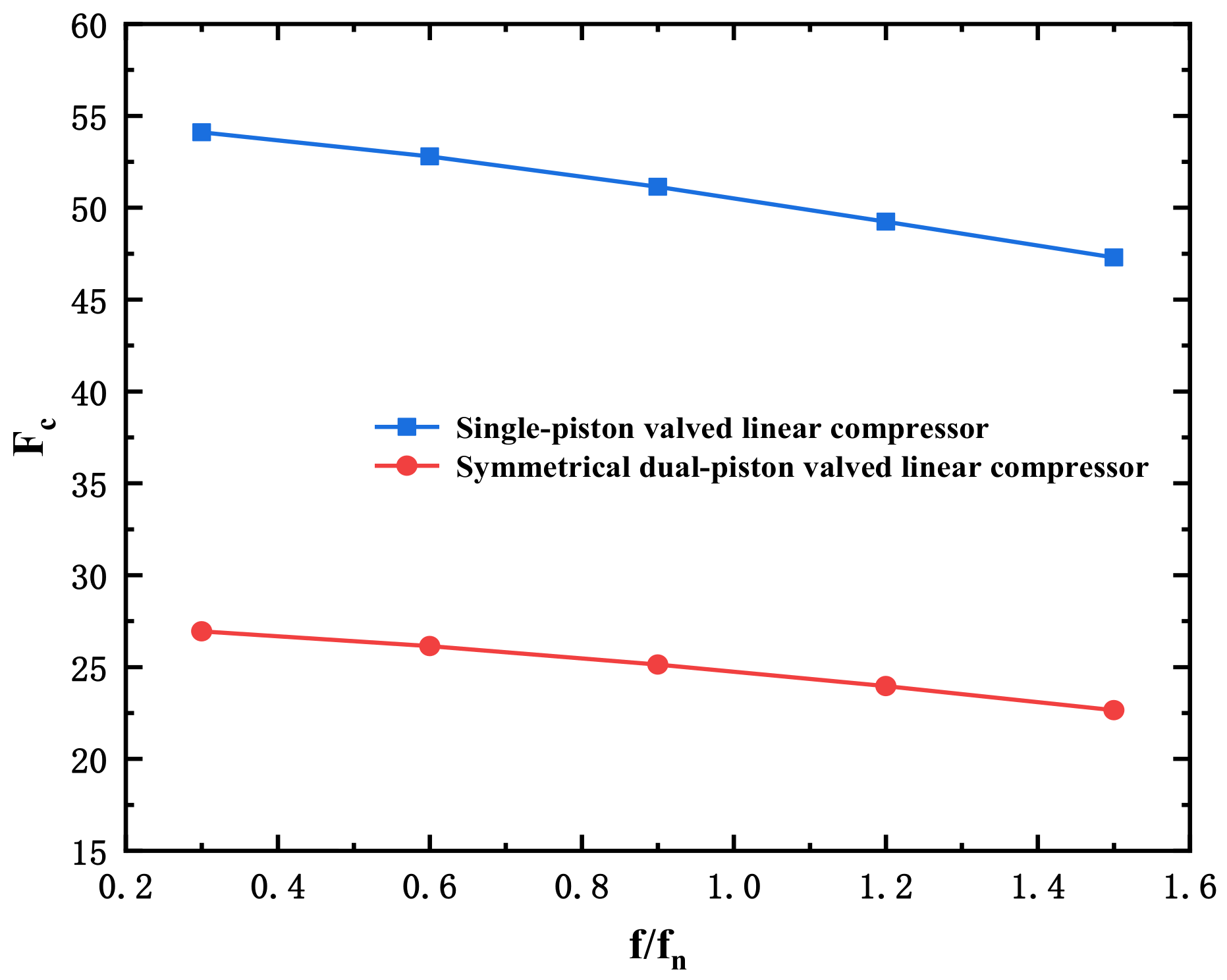
The variance and the same direction ratio of the two types of the linear compressors with different frequencies are shown in Figure 9 and Figure 10. Explicitly, with the increase of the frequency, the variance decreases, and the same direction ratio remains unchanged. Consequently, the efficiency of the linear compressor increases slowly as the frequency increases. Similarly, it could be seen from Figure 9 and Figure 10 that the symmetrical dual-piston valve linear compressor has a lower variance and a higher same direction rate at different frequencies. Accordingly, the efficiency of the SDVLC is higher than the SVLC at different frequencies.

4. Experimental System Introduction

Figure 11 shows a schematic diagram of the experimental system. Figure 12 shows the photo of the experimental system. The main loop consists of a linear compression, a mass flow meter, a cooler, a low-pressure tank, a throttle valve and a high-pressure tank. Other instruments are thermal sensors, pressure sensors, water coolers, gas cylinders, valves, vacuum pumps, collector, computers, power supplies, power meters, current clamps and oscilloscopes.
The linear compressor converts the low temperature and pressure gas into high temperature and pressure. Then the gas is cooled in a cooler. The throttle valve could control the pressure ratio and mass flow of the loop. Mass flow meters could measure the mass flow of the loop. Thermal sensors and pressure sensors are installed at the linear compressor inlet and outlet, they are used to measure the temperature and pressure of the loop. The stroke of the linear compressor is measured by a laser displacement sensor. The power supply provides the power for the linear compressor and the power meter measures the electrical parameters. The current pliers measure the current waveform. The oscilloscope could display the current waveform and displacement waveform. The key parameters are listed in Table 4.

5. Experimental Results and Discussion

By adjusting the input voltage and frequency of the power supply, the stroke and operating frequency of the linear compressor can be adjusted. The operating frequency is expressed as a multiple of the intrinsic frequency f n . The pressure ratio of the system is changed by adjusting the opening of the manual throttle valve. The system operating parameters are shown in Table 5.

5.1. Cures of the Current and Velocity

The experimental investigation is carried out using the SVLC and the SDVLC independently, developed in our laboratory. When the pressure ratio is set to 2.0 and the linear compressors operate at the resonant frequency, the experimental results are shown in Figure 13 and Figure 14.
Actually, it could be seen from Figure 13 and Figure 14 that the current and velocity curves of the SVLC deviate significantly in the last 1⁄2 cycle, while the current and velocity curves of the SDVLC are more consistent. The variance and same direction rate are shown in Table 6.
The variance of the SVLC is 3.05 times as high as that of the SDVLC. The same direction ratio of the SDVLC is 5.71% higher than that of the SVLC. It could be deduced that the efficiency of the SDVLC is higher than that of the SVLC. The deviation of the current and velocity exhibited by the SVLC is inseparable from its structure. The SVLC’s structure causes the load not to be symmetrical during one cycle. When the gas is expanding, the gas force doing the work on the piston causes the current to increase, which is the main reason for the divergence between the current and velocity.

5.2. Isentropic Efficiency

In order to evaluate the efficiency of the linear compressors, the isentropic efficiency η p is used to evaluate that, and could be obtained by Equation (17) [23]:
η p = k k 1 m R g T 1 P 2 P 1 k 1 k 1 P i n
Figure 15 and Figure 16 describe the isentropic efficiency of the SVLC and SDVLC at different pressure ratios and different frequencies. In essence, the isentropic efficiencies of the SDVLC are higher than that of the SVLC at different pressure ratios and different frequencies. The isentropic efficiency decreases when the pressure ratio increases, which is consistent with the calculated results. The isentropic efficiency changes hardly when the frequency increases, which is also consistent with the calculated results. The average isentropic efficiency of the SDVLC is 19.67% higher than that of the single-piston linear compressor at different pressure ratios, while the value is 7% at the different frequencies.

5.3. Volumetric Efficiency

The clearance volume of the linear compressor has an impact on the volumetric efficiency. Particularly, the load of the SVLC is not symmetrical, the displacement of the piston will further affect the volumetric efficiency. The volumetric efficiency of the linear compressor can be obtained by Equation (18) [24]:
η v = 4 V π D 2 S f
where V is the volume flow at the suction port of the linear compressors, D is the piston diameter, S is the piston stroke, and f is the drive frequency.
From Figure 17 and Figure 18, it could be seen that the volumetric efficiencies of the SDVLC are all higher than the SVLC at different pressure ratios and frequencies. As the pressure ratio increases, the volumetric efficiency gradually decreases. The average volumetric efficiency of the SVLC is 79.3% at different pressure ratios. The value of the SDVLC is 83.7%, which is 5.6% higher than the SVLC. As the frequency increases, the volumetric efficiency increases and then decreases hardly. The average volumetric efficiency of the SDVLC is 4.2% higher than that of the SVLC at different frequencies.

5.4. Motor Efficiency

The pistons of the linear compressor are powered by moving coils, and the heat generated by the coil copper resistance is a major factor in the motor loss. The motor efficiency of the linear compressor could be obtained by Equation (19) [25]:
η m = 1 I 2 R e P i n
where I is the effective value of the current, R is the resistance of the copper coil, and P i n is the input power.
Figure 19 and Figure 20 illustrate the motor efficiency of the two types of linear compressors at different pressure ratios and frequencies. As the pressure ratio increases, the motor efficiency increases and then decreases. The average motor efficiency of the SDVLC is 87.5% at different pressure ratios, and 1.9% higher than the SVLC. The motor efficiency changes in the same way at different frequencies. The average motor efficiency of the SDVLC is 86.5% at different frequencies, and 0.24% higher than the SVLC.

6. Conclusions

The paper considers the linear compressor as a single degree of freedom, damped forced vibration system to solve the displacement response. It is deduced that the efficiency is highest when the current is in phase with the velocity. The dynamic equation and the electromagnetic equation of the linear compressor are calculated to obtain the cures of the current and velocity in the time domain. It is found that the current and velocity cures of the SVLC are more deviated after comparison. The variance and the same direction rate are used to evaluate the degree of in-phase between the current and velocity. The SVLC and the SDVLC are tested on the experimental system. The current and velocity cures are obtained respectively. Furthermore, the SVLC and the SDVLC are tested at different pressure ratios and different frequencies. The isentropic efficiency, volumetric efficiency, and motor efficiency of the two types of linear compressors are obtained after the experiments.
  • The variance of the SVLC is 2.04 times that of the SDVLC, but the same direction rate of the SDVLC is 29.51% higher than that of the SVLC. The current and velocity deviation of the SVLC association efficiency decrease. Therefore, it could be concluded that the efficiency of the SDVLC is higher than the SVLC.
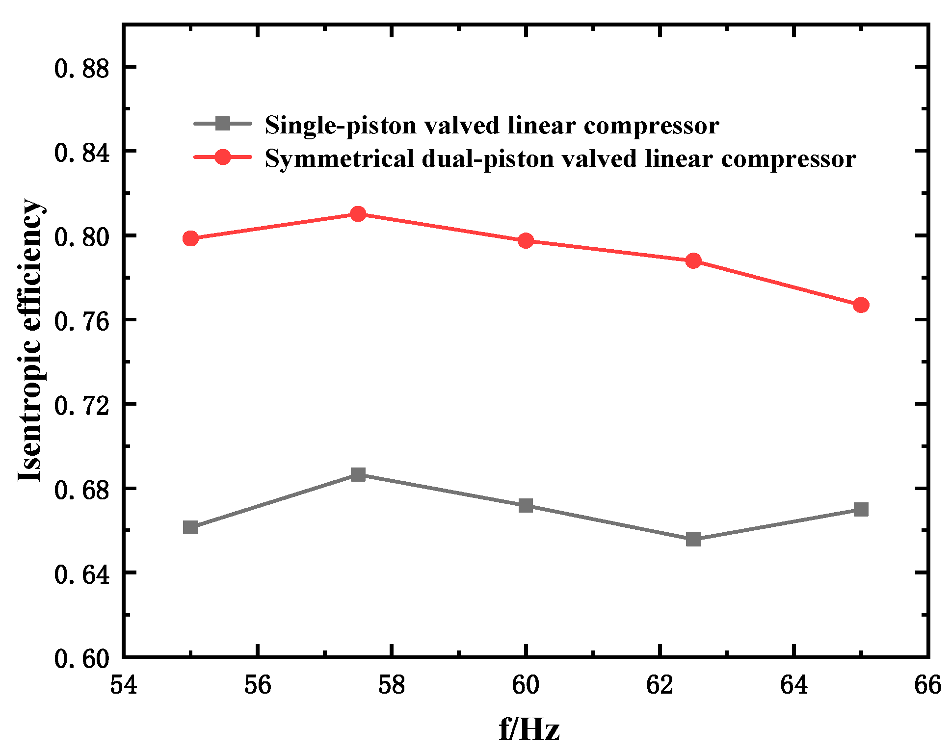
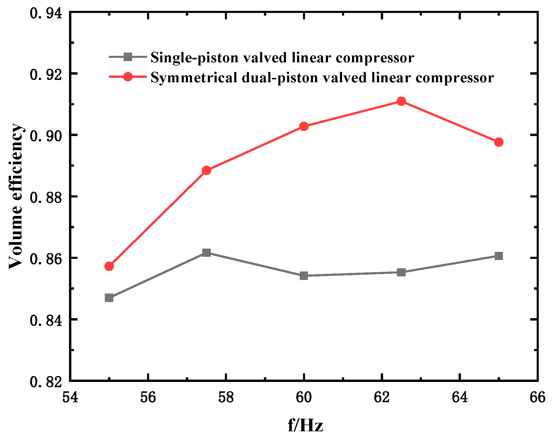
  • The experimental results and the calculated results have the same tendency. Under different working conditions, the isentropic efficiency of the SDVLC is higher than that of the SVLC. The average isentropic efficiency, average volumetric efficiency and average motor efficiency of the SDVLC are 19.67%, 5.6% and 1.9% higher than that of the SVLC at different pressure ratios. The values are 7%, 4.2% and 0.24% at different frequencies.
  • The reason for the higher efficiency of the SDVLC is that the current and velocity are more in-phase in the time domain. The in-depth reason is that the load of the SVLC is asymmetric in one cycle, this will cause the current to increase during the half cycle, making the deviation from the velocity. Therefore, the efficiency of the SDVLC is higher than the SVLC.
We conclude that the efficiency is the highest when the current and velocity are in the same phase by solving the dynamic equation. For the linear compressors, the efficiency of the double-piston structure is higher than that of the single-piston structure. We explain the reason for the efficiency difference in terms of the relationship between the current and velocity.
In the future, the efficiency of the single-piston linear compressors will be improved by adjusting the piston offset and reducing the clearance and observing the relationship between the comparative current and speed. It may be possible to increase the efficiency by modulating the current with a device, such as a signal generator that is more in tune with the speed.

Author Contributions

Conceptualization, J.C. and Z.H.; methodology, Y.N., Y.L. (Yanjie Liu) and Z.H.; software, Z.H.; validation, Z.H., Y.L. (Yuanli Liu) and C.Z.; formal analysis, Z.H.; investigation, Z.H.; resources, Z.H.; data curation, Z.H.; writing—original draft preparation, Z.H.; writing—review and editing, Z.H., Y.L. (Yuanli Liu) and C.Z.; visualization, E.X. and Z.H.; supervision, J.C., Y.N., Y.L. (Yanjie Liu); project administration, Y.N., Y.L. (Yanjie Liu); funding acquisition, J.C. All authors have read and agreed to the published version of the manuscript.

Funding

This research was funded by the Strategic Priority Research Program of Chinese Academy of Sciences (Grant No. XDA18000000, No. XDA18040000), and the Research Equipment Development Project of Chinese Academy of Sciences (Grant No. ZDKYYQ20220004).

Data Availability Statement

Not applicable.

Conflicts of Interest

The authors declare no conflict of interest. The funders had no role in the design of the study; in the collection, analyses, or interpretation of data; in the writing of the manuscript; or in the decision to publish the results.

References

  1. Ma, Y.X. Study on Multi-Stage Throttling Process Driven by Three-Stage Linear Compressor in Space Liquid Helium Temperature Region; Chinese Academy of Sciences: Beijing, China, 2017. [Google Scholar]
  2. Lindensmith, C.A.; Bowman, R.C.; Wade, L.A.; Crumb, D. Cryocooler Options for NGST and other Space Applications. In Next Generation Space Telescope Science and Technology; Jet Propulsion Laboratory, California Institute of Technology: Pasadena, CA, USA, 2000; Volume 207, p. 106. [Google Scholar]
  3. Sugita, H.; Sato, Y.; Nakagawa, T.; Murakami, H.; Kaneda, H.; Enya, K.; Murakami, M.; Tsunematsu, S.; Hirabayashi, M. Development of mechanical cryocoolers for the Japanese IR space telescope SPICA. Cryogenics 2008, 48, 258–266. [Google Scholar] [CrossRef]
  4. Lee, H.; Ki, S.H.; Jung, S.S.; Rhee, W. The innovative green technology for refrigerators development of innovative linear compressor. In Proceedings of the International Compressor Engineering Conference, West Lafayette, IN, USA, 14–17 July 2008. [Google Scholar]
  5. Liu, L.; Zhang, H.; Ding, L.; Xiang, Z.Z.; Tang, Y.H.; Jiang, Z.H.; Liu, S.S. Study on Key Influencing Factors of Output Characteristics of a Valved Linear Compressor. Chin. J. Refrig. Technol. 2019, 39, 34–38. [Google Scholar]
  6. Ding, L.; Zhang, H.; Sha, X.; Liu, S.; Jiang, Z.; Wu, Y. Study on the establishing-process of piston offset in the helium valved linear compressor under different operating parameters. Int. J. Refrig. 2022, 133, 80–89. [Google Scholar] [CrossRef]
  7. Liu, Y.; Sun, J.; Xun, Y.; Huang, Z.; Cai, J.; Li, C. Experimental investigation of the discharge valve dynamics in an oil-free linear compressor for Joule-Thomson throttling refrigerator. Appl. Therm. Eng. 2022, 209, 118288. [Google Scholar] [CrossRef]
  8. Kulyk, M.; Lastivka, I.; Tereshchenko, Y. EFFECT OF HYSTERESIS IN AXIAL COMPRESSORS OF GAS-TURBINE ENGINES. Aviation 2012, 16, 97–102. [Google Scholar] [CrossRef]
  9. Chao, Y.; Wang, B.; Li, H.; Xia, M.; Zhao, Q.; Wang, H.; Li, R.; Chen, J.; Gan, Z. A two-stage thermally-coupled pulse tube cryocooler working at 35 K for space application. Acta Astronaut. 2022, 191, 193–203. [Google Scholar] [CrossRef]
  10. Plachta, D.; Stephens, J.; Johnson, W.; Zagarola, M. NASA cryocooler technology developments and goals to achieve zero boil-off and to liquefy cryogenic propellants for space exploration. Cryogenics 2018, 94, 95–102. [Google Scholar] [CrossRef] [Green Version]
  11. Deserranno, D.; Zagarola, M.; Li, X.; Mustafi, S. Optimization of a Brayton cryocooler for ZBO liquid hydrogen storage in space. Cryogenics 2014, 64, 172–181. [Google Scholar] [CrossRef]
  12. Jiang, H.; Li, Z.; Liang, K. Performance of a linear refrigeration compressor with small clearance volume. Int. J. Refrig. 2020, 109, 105–113. [Google Scholar] [CrossRef]
  13. Ding, L.; Zhang, H.; Sha, X.; Liu, S.; Jiang, Z.; Wu, Y. Experimental investigation on helium valved linear compressors with different active offsets. Cryogenics 2022, 124, 103483. [Google Scholar] [CrossRef]
  14. Liang, K. A review of linear compressors for refrigeration. Int. J. Refrig. 2017, 84, 253–273. [Google Scholar] [CrossRef]
  15. Liang, K.; Stone, R.; Dadd, M.; Bailey, P. The effect of clearance control on the performance of an oil-free linear refrigeration compressor and a comparison between using a bleed flow and a DC current bias. Int. J. Refrig. 2016, 69, 407–417. [Google Scholar] [CrossRef] [Green Version]
  16. Zou, H.; Zhang, L.; Peng, G.; Tian, C. Experimental investigation and performance analysis of a dual-cylinder opposed linear compressor. J. Mech. Sci. Technol. 2011, 25, 1885–1892. [Google Scholar] [CrossRef]
  17. Chen, H.; Liu, X.; Zou, X.; Lv, Z.; Li, W.; Chen, C. Study of the moving offset characteristics of multi-loop moving coil linear compressor. Int. J. Refrig. 2022, 133, 289–301. [Google Scholar] [CrossRef]
  18. Huang, Q.; Ding, L.; Sha, X.; Liu, S.; Jiang, Z.; Dong, D. Experimental investigation on piston offset and performance of helium valved linear com-pressor with an external gas bypass. Int. J. Refrig. 2022, in press. [Google Scholar] [CrossRef]
  19. Marquardt, E.; Radebaugh, R.; Kittel, P. Design equations and scaling laws for linear compressors with flexure springs. Cryocoolers 1993, 7, 783–804. [Google Scholar]
  20. Sun, J.; Li, J.; Liu, Y.; Huang, Z.; Cai, J. A Novel Oil-free Dual Piston Compressor Driven by a Moving Coil Linear Motor with Capacity Regulation Using R134a. Sustainability 2021, 13, 5029. [Google Scholar] [CrossRef]
  21. Gavin, H.P. Vibrations of Single Degree of Freedom Systems; Class Note CEE201; Department of Civil and Environmental Engineering, Duke University: Dehan, NC, USA, 2014. [Google Scholar]
  22. Bradshaw, C.R.; Groll, E.A.; Garimella, S.V. A comprehensive model of a miniature-scale linear compressor for electronics cooling. Int. J. Refrig. 2011, 34, 63–73. [Google Scholar] [CrossRef] [Green Version]
  23. Sun, J.; Li, J.; Liu, Y.; Huang, Z.; Wang, N.; Cai, J. Experimental Research on Piston Offset and Performance of a High-Efficiency Moving Coil Linear Compressor for JT Throttle Refrigerator; International Cryocooler Conference, Inc.: Boulder, CO, USA, 2021. [Google Scholar]
  24. Bijanzad, A.; Hassan, A.; Lazoglu, I.; Kerpicci, H. Development of a new moving magnet linear compressor. Part B: Performance analysis. Int. J. Refrig. 2020, 113, 94–102. [Google Scholar] [CrossRef]
  25. Wei, Y.; Zuo, Z.; Jia, B.; Feng, H.; Liang, K. Influence of piston displacement profiles on the performance of a novel dual piston linear com-pressor. Int. J. Refrig. 2020, 117, 71–80. [Google Scholar] [CrossRef]
Figure 1. (a) the compositions of a SVLC; (b) the compositions of a SDVLC (1. sight window 2. discharge valve 3. suction valve 4. flexure spring 5. outer iron 6. inner iron 7. cylinder 8. piston 9. spindle 10. permanent magnet 11. coil).
Energies 15 08760 g001aEnergies 15 08760 g001b
Figure 2. Schematic diagram of a single-degree-of-freedom, damped forced vibration system.
Energies 15 08760 g002
Figure 3. Schematic diagram of the force balance of the linear compressor mover.
Energies 15 08760 g003
Figure 4. The cylinder of a SDVLC.
Energies 15 08760 g004
Figure 5. The calculated current and speed curves of the SVLC.
Energies 15 08760 g005
Figure 6. The calculated current and speed curves of the SDVLC.
Energies 15 08760 g006
Figure 7. Variances of the two types of linear compressors under different pressure ratios.
Energies 15 08760 g007
Figure 8. The same direction ratios of the two types of linear compressors under different pressure ratios.
Energies 15 08760 g008
Figure 9. Variances of the two types of linear compressors under a different frequency.
Energies 15 08760 g009
Figure 10. The same direction ratios of the two types of linear compressors under a different frequency.
Energies 15 08760 g010
Figure 11. Schematic diagram of the experimental system.
Energies 15 08760 g011
Figure 12. Photo of the experimental system.
Energies 15 08760 g012
Figure 13. The current and velocity of the SVLC, obtained from the experiment.
Energies 15 08760 g013
Figure 14. The current and velocity of the SDVLC, obtained from the experiment.
Energies 15 08760 g014
Figure 15. The isentropic efficiencies of the two types of linear compressors at different pressure ratios, obtained from the experiments.
Energies 15 08760 g015
Figure 16. The isentropic efficiencies of the two types of linear compressors at different frequencies, obtained from the experiments.
Energies 15 08760 g016
Figure 17. The volumetric efficiencies of the two types of linear compressors at different pressure ratios, obtained from the experiments.
Energies 15 08760 g017
Figure 18. The volumetric efficiencies of the two types of linear compressors at different frequencies, obtained from the experiments.
Energies 15 08760 g018
Figure 19. The motor efficiencies of the two types of linear compressors at different pressure ratios, obtained from the experiments.
Energies 15 08760 g019
Figure 20. The motor efficiencies of the two types of linear compressors at different frequencies, obtained from the experiments.
Energies 15 08760 g020
Table 1. Working processes of the SDVLC.
ProcessPiston DisplacementLeft CylinderRight Cylinder
aEnergies 15 08760 i001CompressionExpansion
bEnergies 15 08760 i002CompressionSuction
cEnergies 15 08760 i003DischargeSuction
dEnergies 15 08760 i004ExpansionCompression
eEnergies 15 08760 i005SuctionCompression
fEnergies 15 08760 i006SuctionDischarge
Table 2. The parameters of the linear compressor.
ParameterSVLCSDVLC
Suction pressure ( P c ) 1 MPa1 MPa
Discharge pressure ( P d )2 MPa2 MPa
Diameter of the piston ( D ) 20 mm20 mm
Mass of the mover ( m ) 1 kg1 kg
Stiffness of the flexure spring ( K s ) 200 N/m200 N/m
Thrust coefficient ( K e ) 50 N/A50 N/A
Equivalent inductance ( L e ) 0.2 H0.2 H
Equivalent resistance ( R e ) 1   Ω 1   Ω
Mechanical damping coefficient ( c f ) 0.20.2
Table 3. Comparison of the variance and same direction rate between SVLC and SDVLC, obtained by the calculation.
VariancesSame Direction Rates
SVLC50.520.715
SDVLC24.760.926
Table 4. The list of instruments in the experimental system.
InstrumentsModelQuantityInformation
Data acquisition cardNI PCI-61431Sample rate: 250 KS/s;
Number of channels: 8;
Data acquisition cardKeithley 77001Sample rate: 1 S/s;
Mass flow meterSincerity DMF-1-S31Accuracy: ±0.5%;
Platinum resistorPT1004Accuracy: ±0.1 K;
Static pressure transducerHongkong Huibang L61-K4Accuracy: ±0.25%;
Laser displacement sensorKeyence LK-H0801Accuracy: ±0.02%;
Displacement range: ±18 mm;
Power supplyItech IT78001Voltage range: 0–600 V;
Current range: 0–30 A;
Power meterHangzhou Yuanfang PF98331Accuracy: ±1%;
Current pliersTektronix A6221Maximum current: 100 A;
Response frequency: 100 kHz;
OscilloscopeTektronix Mdo341Bandwidth: 200 MHz;
Table 5. The system operating parameters.
ParametersValue
Fill pressure (MPa)0.7
Stroke (mm)10
Working fluid N 2
Operating frequency ( f n )0.8, 1.0, 1.2, 1.4, 1.6
Pressure ratio2.0, 2.5, 3.0, 3.5
Table 6. Comparison of the variance and same direction rate between the SVLC and SDVLC obtained by experiment.
Type of Linear CompressorVariancesSame Direction Rates
SVLC8.790.805
SDVLC2.880.851
Publisher’s Note: MDPI stays neutral with regard to jurisdictional claims in published maps and institutional affiliations.

