
Waveform-Similarity-Based Protection Scheme for AC Transmission Lines of MMC-HVDC System with Offshore Wind Farms

1
Shenzhen Power Supply Bureau Co., Ltd., Shenzhen 518001, China
2
Key Laboratory of Smart Grid of Ministry of Education, Tianjin University, Tianjin 300072, China
*
Author to whom correspondence should be addressed.
Energies 2022, 15(23), 9107; https://0-doi-org.brum.beds.ac.uk/10.3390/en15239107
Submission received: 4 November 2022
/
Revised: 24 November 2022
/
Accepted: 29 November 2022
/
Published: 1 December 2022
(This article belongs to the Special Issue Advances in DC Technology for Modern Power Systems)
Abstract
:The modular multilevel converter (MMC) has become a very promising technology for long-distance and large-capacity transmission of offshore wind power. However, both sides of the AC transmission line at the sending end are controllable electronic power devices, resulting in difficulty in fault identification and inapplicability of traditional differential protection schemes. In order to solve this problem, a wave-similarity-based protection scheme is proposed for AC transmission line faults. Firstly, the symmetrical and asymmetrical fault current characteristics of the double-fed induction generator (DFIG) and MMC are studied, indicating that the fault current characteristics are obviously different from the synchronous units. Secondly, the wave-similarity-based protection scheme is proposed based on the different wave forms of the fault currents of the MMC and DFIG. When the similarity coefficient is less than the margin coefficient, there is a fault in this phase. Moreover, the proposed wave-similarity-based protection scheme can identify all types of short-circuit faults correctly and is not affected by the transition resistance. Finally, simulations of an MMC-HVDC system with offshore wind farms are conducted to validate the effectiveness and correctness of the proposed protection scheme.
1. Introduction
Offshore wind energy has advantages such as being rich in resources, renewable, and suitable for large-scale development, so offshore wind power has a great prospect in the future [1,2,3]. Connecting offshore wind farms to AC systems through voltage-source-converter-based high-voltage DC system (VSC-HVDC) can achieve AC/DC isolation, making offshore wind farms unaffected by the voltage fluctuations of the AC power system, enhancing the fault ride through the capability of wind farms [4,5,6]. Therefore, VSC-HVDC with offshore wind farms has become a popular grid access mode (see, for example, the “Rudong” offshore wind farm project in China) [7,8].
Compared with the two-level and three-level VSC topologies, the modular multilevel converter (MMC) has the advantages of strong scalability, high degree of modularization, good power quality, low switching frequency, and so on, and it has become the preferred scheme for HVDC systems [9,10,11]. In addition, double-fed induction generators (DFIGs) are the main types of wind power generation at present due to their high technical maturity and good economy.
When a short-circuit fault occurs, due to the input of crowbar resistance, the rotor speed of DFIG is different from the synchronous speed. Its fault current not only includes 50 Hz components and damping DC components, but also includes damping frequency components of 35 to 65 Hz. Therefore, the fault current characteristics of DFIG are obviously different from traditional synchronous units [12,13]. Under an asymmetrical fault, the positive and negative sequence impedances of DFIG are not equal, and high-order harmonics are generated, so the traditional pilot protection based on synchronous units cannot be fully applied. It is pointed out in [14] that due to the frequency shift of the DFIG, the pilot protection of AC lines based on synchronous units will produce the phenomena of rejection and maloperation. To solve this problem, the authors of [15] propose a novel protection scheme for the comparison of current amplitude difference. The authors of [16] adopt the least square method to identify the fault line parameters and solve the problem of distance protection failure when the DFIG is grounded through high resistance. The authors of [17] propose using the magnitude of the comprehensive impedance modulus to distinguish internal and external faults. However, the above protection is still designed based on synchronous units. When a short-circuit fault occurs, the rotation frequency component of the fault current is far greater than the power frequency component, and the new protection will still be affected by the frequency offset.
When a fault occurs on the AC side of the sending-end MMC, due to the influence of the control strategy, its short circuit current is also significantly different from that of the synchronous units [18]. The authors of [19] propose a Euler–Lagrange-model-based MMC controller, which improves the dynamic control performance of the MMC. On this basis, the authors of [20] propose a positive and negative sequence current control based on the Euler–Lagrange model for negative sequence current caused by unbalanced grid voltage or asymmetric fault of the AC system.
Therefore, the fault currents of both DFIGs and MMCs cause the performance of the traditional pilot protection based on synchronous units to be inapplicable. The main contributions of this paper can be summarized as follows:
- (1)
- The analytical expressions of the fault currents of DFIG and MMC are analyzed.
- (2)
- The adaptability of the traditional differential protection to the AC transmission line at the sending end is verified, and it is found that traditional differential protection cannot accurately identify the faults.
- (3)
- According to the waveform difference of fault currents on both sides of the fault point, a new principle of pilot protection based on waveform similarity is proposed, and all types of short-circuit faults can be identified correctly.
The rest of this paper is organized as follows. In Section 2, the fault current characteristics of the AC line faults at the sending end are studied. The novel waveform-similarity-based protection scheme is proposed in Section 3. Simulations of a DFIG wind farm via MMC-HVDC system under different faults have been conducted in PSCAD/EMTDC to validate the effectiveness of the proposed protection scheme in Section 4. Finally, conclusions and future work are provided in Section 5.
2. Fault Current Characteristics
The topology of the MMC-HVDC with offshore wind farms is shown in Figure 1. The wind farms are collected and boosted through AC lines, and then connected to the onshore power grid through the MMC-HVDC system. MMC1 works at the vf control mode, providing a stable AC voltage for integration of DFIGs. In addition, MMC2 works at the DC voltage control mode, making the DC voltage fluctuate within a limited range no matter what the transmission power is.
2.1. Fault Current Characteristics of DFIG
- (1)
- Three-phase short-circuit
When a three-phase short circuit fault occurs at the DFIG terminal, the voltages before and after the fault are and , respectively. In addition, . Ignoring the stator resistance, the stator flux before the fault is
where is the stator flux before the fault, is the AC voltage of the DFIG terminal, is the speed of the stator, and is the initial phase angle.
Similarly, the stator flux after the fault is
where is the stator flux after the fault.
According to the principle of flux conservation, the stator flux during the fault is
where is the stator flux during the fault, is the fault time, and is the stator damping time constant.
The rotor flux before the fault is
where is the rotor flux before the fault, is the mutual inductance of the stator and the rotor, and is the stator inductance.
After the fault, the crowbar resistance is switched on instantaneously, and the rotor voltage drops to 0. The rotor flux after the fault is
where is the rotor flux after the fault, and is the rotor inductance.
According to the principle of flux conservation, the rotor flux during the fault is
where is the rotor flux during the fault, is the fault time, and is the rotor damping time constant.
Taking (3) and (6) into consideration, the fault current of DFIG during the fault is
where is the fault current of DFIG during the fault.
- (2)
- Asymmetrical fault
When an asymmetric short circuit fault occurs at the DFIG terminal, its port voltage is
where is the negative sequence voltage of DFIG.
The initial flux of the negative sequence stator and the rotor is 0. Since the stator flux cannot change suddenly, the stator flux generated by the negative sequence voltage is
According to the principle of flux conservation, the rotor flux linkage generated by the negative sequence voltage is
The negative sequence stator fault current is
According to (7) and (11), the fault current of DFIG during the asymmetrical fault is
2.2. Fault Current Characteristics of MMC at the Sending End
- (1)
- Three-phase short-circuit
The inertia of the MMC is small, and the response time of the controller is between several milliseconds and more than ten milliseconds. After the fault occurs and before the controller responds, the fault current of the MMC is similar to the fault current of the conventional unit, but after the controller works, the fault current characteristics of the MMC will change.
When the fault occurs, the AC voltage decreases. Then, the order of the d-component of the current is
where is the order of the d-component of the current, is order of the d-component of the AC voltage, is the measured d-component of the AC voltage, is the scale coefficient, and is the integral coefficient.
As remains unchanged, when the fault occurs, the output of the outer loop will increase. Finally,, and is the maximum limiting value of the d- outer loop. Similarly,, and is the maximum limiting value of the q- outer loop.
Therefore, the positive sequence network of the MMC is equivalent to an AC current source affected by both d-axis current and q-axis current.
- (2)
- Asymmetrical fault
When an asymmetric fault occurs, the AC bus voltage of the MMC will no longer be balanced, resulting in negative sequence components. In order to prevent the superposition of the negative sequence current and positive sequence current from exceeding the upper safety limit, the MMC generally adopts the negative sequence current suppression strategy. The basic principle of negative sequence current suppression is to decouple the inner loop current control system into an independent positive sequence control system and negative sequence control system.
To ensure that no negative sequence current is generated in the system under any circumstances, the reference values of negative sequence active current and reactive current are generally set to 0. After the negative sequence current suppression strategy is adopted, the negative sequence loop current is basically suppressed to 0, but the negative sequence voltage still exists. Therefore, for the positive and negative sequence decoupling control mode with negative sequence suppression strategy, the equivalent impedance of the negative sequence loop of the converter station is large when the AC line of the MMC has an asymmetric fault.
Based on the above analysis of the fault characteristics of MMC and DFIG, it can be seen that there is a huge difference between the amplitude and phase angle of the short-circuit current injected by the MMC and DFIG to the fault point, which means the waveform difference is obvious. Therefore, Tanimoto similarity can be used to quantitatively measure this waveform difference and serve as the criterion for the action of pilot protection.
3. Waveform-Similarity-Based Protection Scheme
When the external fault of the AC transmission line at the sending end occurs, the fault currents provided by the DFIG and the MMC to the fault point are equal in size and opposite in direction, and the waveform is basically the same. However, when the internal fault occurs, the waveform of the fault currents provided by DFIG and MMC are obviously different. Tanimoto similarity is used to quantitatively measure this waveform difference. The proposed protection can correctly distinguish internal and external faults and act quickly and effectively in the case of internal fault of the AC transmission line.
At the same time, this waveform-similarity-based protection does not need all of the power frequency cycle sampling data, which can effectively avoid the problem that the pilot protection cannot operate correctly and effectively due to fast blocking of the MMC.
3.1. Principle of Tanimoto Similarity Theory
The protection devices at both ends of the AC transmission line conduct discrete sampling of each phase current to form two groups of one-dimensional arrays, respectively.
Note that and represent these two groups of one-dimensional data, where n is the number of sampling points in the sampling period, and the calculation formula for measuring the difference between these two groups of one-dimensional arrays with Tanimoto similarity is [21]
According to the inequality principle, the value range of is [0, 1]. If , then , which indicates that the two groups of waveforms are identical and the correlation is the strongest, but this phenomenon will not happen in the AC transmission line faults. If , then , indicating that the two groups of waveforms have the same size, opposite direction, and the strongest negative correlation, which means the external fault occurs. When the value is less than 1, it indicates that there is difference between the two groups of data, and the correlation is weak, which means the internal fault of the protection line occurs.
3.2. Waveform-Similarity-Based Protection Scheme
When the internal fault occurs, the MMC at the sending end will produce a low-voltage overcurrent phenomenon. To prevent the MMC from being damaged by overcurrent, it may be blocked within 5–10 ms. According to this, the sampling period of the Tanimoto similarity protection algorithm can be set as 10 ms, and the discrete current sampling frequency is set as 2.5 kHz. In this way, 25 data points can be sampled in a cycle, and the data is sufficient. When an external fault occurs, the current at both ends of the line is the same in size and opposite in direction, and the Tanimoto similarity calculation value is 1. When the line has an internal fault, the current waveforms at both ends of the line are obviously different, and the Tanimoto similarity calculation value is less than 1 and close to 0.
For the proposed protection scheme, the sampling data error at both ends mainly comes from synchronization error, CT transmission error, and amplitude error. The error coefficient is determined as 0.95, the margin coefficient is determined as 0.95, the protection setting value is , and the protection action condition is
The steps of the proposed waveform similarity protection scheme are
- (1)
- The current of each phase on both sides of the line shall be sampled with a sampling frequency of 2.5 kHz and a sampling period of 5 ms, and the Tanimoto similarity shall be calculated according to Equation (14).
- (2)
- Equation (15) is used as the criterion to judge the protection action. When the calculated Tanimoto similarity of a phase is less than 0.9025, it is a fault phase. Then, phase protection acts. When the calculated value is always greater than 0.9025, it is a non-fault phase.
- (3)
- If the calculated value of three-phase Tanimoto similarity is greater than 0.9025, it means that the system operates normally or the external fault of the protection line occurs.
4. Simulation Studies
Simulations of a DFIG wind farm via MMC-HVDC system under different types of AC line have been conducted in PSCAD/EMTDC to validate the effectiveness of the proposed waveform-similarity-based protection scheme. The topology is shown in Figure 1. The capacity of a DFIG is 5 MW, and the wind farm consists of 190 DFIGs. In addition, the parameters of the DFIG are shown in Table 1, and the parameters of the MMC are shown in Table 2. The AC line is 50 km, the positive sequence reactance is , the zero sequence reactance is , and the positive sequence and zero sequence capacitors are and , respectively.
4.1. Fault Current Characteristics of MMC and DFIG
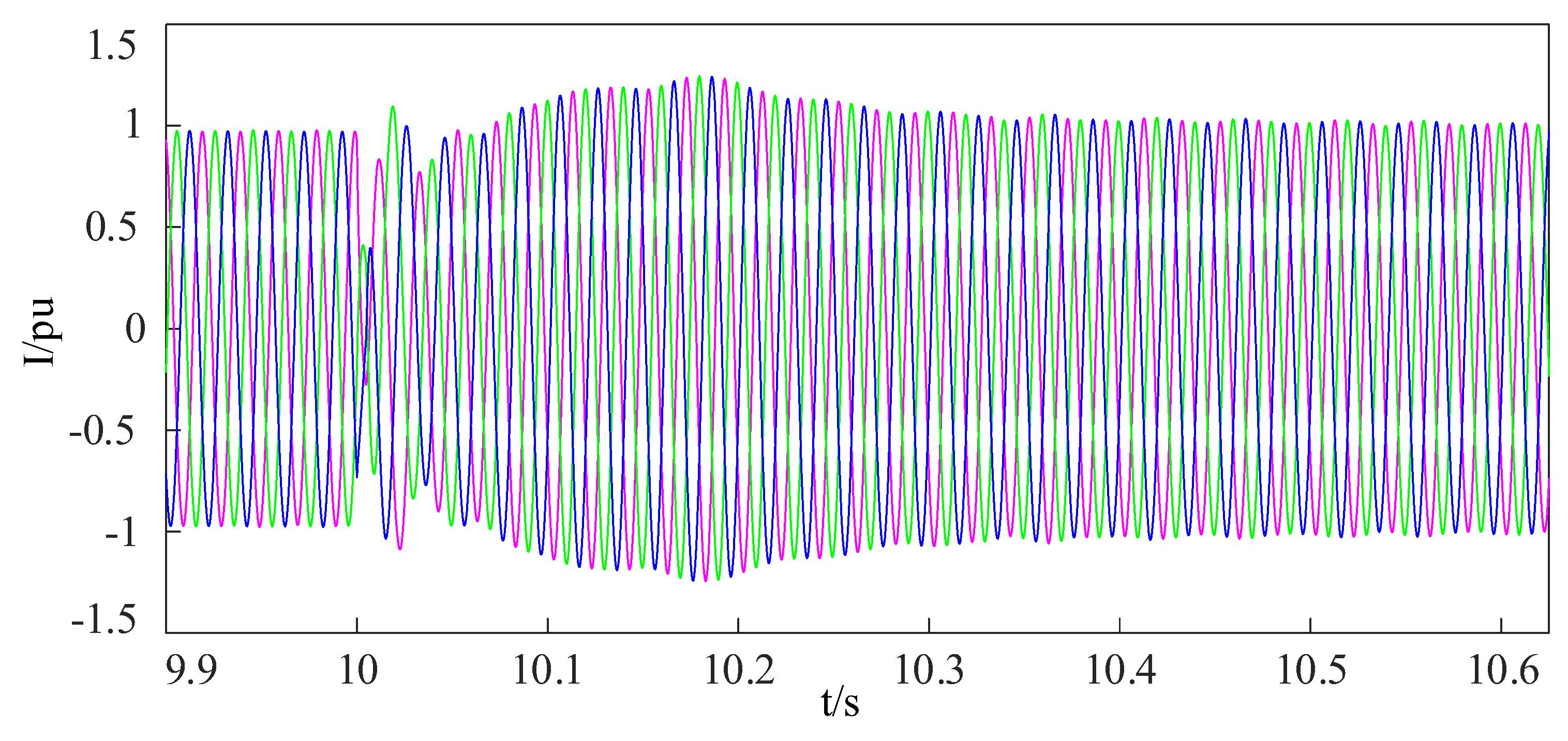
Assume a three-phase short-circuit occurs at the point 20 km from the sending MMC at t = 10 s, and the fault duration is 0.625 s.
The terminal voltage of the DFIG drops to 0.23 pu, and the comparison between the waveform is calculated by Equation (12). The simulation waveform of the stator short-circuit current of a single DFIG is shown in Figure 2.
It can be seen from Figure 2 that the short-circuit current sent by DFIG is obviously different from that of the synchronous unit during the short-circuit fault. The transfer frequency component of the DFIG short-circuit current accounts for a large proportion, and its damping time constant is large, so the current damping process is slower than that of the synchronous unit.
The simulation result of the fault current of the sending-end MMC is shown in Figure 3. It can be seen that the sending-end MMC can be completely equivalent to a controlled current source with an amplitude of 1 p.u. during fault due to the low-voltage current-limiting control strategy.
4.2. Waveform-Similarity-Based Protection Scheme
Traditional differential protection is applied to the AC transmission line at the sending end. The ratio of differential protection action current to braking current is shown in Figure 4. The braking coefficient of general differential protection is set to 0.8. It can be seen from Figure 4 that traditional differential protection may not act before the sending-end MMC is blocked, resulting in incorrect action of the protection.
The simulation results of the proposed protection scheme under different types of faults are shown in Figure 5.
It can be seen from Figure 5 that under different types of faults, the waveform-similarity-based protection scheme can correctly and effectively act.
4.3. Influence of the Transition Resistance on the Proposed Protection
There may be some transition resistances in the short-circuit fault. The influence of the transition resistance on the proposed protection performance must be considered. The maximum transition resistance of 220 kV system is about . The calculation results of the similarity coefficients of different types of faults with different transition resistances (, , ) are shown in Table 1.
It can be seen from Table 2 that the waveform similarity coefficient tends to increase with the increase of the transition resistance, but the protection still has good performance and is still applicable in the case of high-resistance fault.
5. Conclusions
In this paper, the short-circuit current characteristics of DFIG and MMC are analyzed in detail, and it is concluded that the current amplitude and phase angle of the DFIG and MMC at MMC are significantly different from those of the synchronous unit, which indicates that traditional pilot protection may not be fully applied to AC transmission lines’ protection of the sending end of MMC-HVDC. Therefore, a waveform-similarity-based protection scheme is proposed. The theoretical and the simulation results show that the proposed protection can act quickly and effectively under various types of short-circuit faults and is not affected by the size of transition resistance.
The engineering application of the proposed waveform-similarity-based protection scheme should be considered, and the location of the fault should be studied in the further work.
Author Contributions
Conceptualization, Y.W. (Yijun Wang); methodology, Z.W. and R.Z.; validation, supervision, Y.W. (Yizhen Wang); project administration, Y.W. (Yizhen Wang); investigation, N.M. All authors have read and agreed to the published version of the manuscript.
Funding
This research received no external funding.
Conflicts of Interest
The authors declare no conflict of interest.
References
- Wang, L.; Wei, J.; Wang, X.; Zhang, X. The development and prospect of offshore wind power technology in the world. In Proceedings of the 2009 World Non-Grid-Connected Wind Power and Energy Conference, Nanjing, China, 13 November 2009; pp. 1–4. [Google Scholar]
- Fu, Y.; Liu, Z.; Zhao, L.; Tian, X.; Yuan, Z.; Yang, B. Offshore wind power development and transmission technology research in Shandong. In Proceedings of the 2022 IEEE/IAS Industrial and Commercial Power System Asia (I&CPS Asia), Shanghai, China, 8–11 July 2022; pp. 195–199. [Google Scholar]
- Gao, G.; Wu, H.; Wang, X. Converter control impacts on efficacy of protection relays in HVDC-connected offshore wind farms. In Proceedings of the 2022 IEEE 13th International Symposium on Power Electronics for Distributed Generation Systems (PEDG), Kiel, Germany, 26–29 June 2022; pp. 1–6. [Google Scholar]
- Guo, Y.; Gao, H.; Xing, H.; Wu, Q.; Lin, Z. Decentralized Coordinated Voltage Control for VSC-HVDC Connected Wind Farms Based on ADMM. IEEE Trans. Sustain. Energy 2019, 10, 800–810. [Google Scholar] [CrossRef] [Green Version]
- Edrah, M.; Lo, K.L.; Anaya-Lara, O.; Elansari, A. Impact of DFIG based offshore wind farms connected through VSC-HVDC link on power system stability. In Proceedings of the 11th IET International Conference on AC and DC Power Transmission, Birmingham, UK, 10–12 February 2015; pp. 1–7. [Google Scholar]
- Lin, C.-H.; Wu, Y.-K. Coordinated frequency control strategy for VSC-HVDC-connected wind farm and battery energy Storage system. In Proceedings of the 2022 IEEE Industry Applications Society Annual Meeting (IAS), Detroit, MI, USA, 9–14 October 2022; pp. 1–10. [Google Scholar]
- Li, J.; Xie, X.; Yang, J.; Li, H.; Shi, Z.; Wang, K.; Fu, C.; Yang, W. Analysis and suppression of subsynchronous oscillation of Rudong wind power through MMC-HVDC system. In Proceedings of the 2021 Annual Meeting of CSEE Study Committee of HVDC and Power Electronics (HVDC 2021), Hybrid Conference, China, 28–30 December 2021; pp. 151–158. [Google Scholar]
- Chen, Z.; Li, G.; Kong, X.; Zhang, C.; Bin, Z.; Xu, J. Analysis of wide-band oscillation characteristics of rudong offshore wind farm connected to the grid through VSC-based DC transmission system. In Proceedings of the 2022 7th Asia Conference on Power and Electrical Engineering (ACPEE), Hangzhou, China, 15–17 April 2022; pp. 706–711. [Google Scholar]
- Wang, Y.; Wen, W.; Zhang, C.; Chen, Z.; Wang, C. Reactor Sizing Criterion for the Continuous Operation of Meshed HB-MMC-Based MTDC System Under DC Faults. IEEE Trans. Ind. Appl. 2018, 54, 5408–5416. [Google Scholar]
- Wang, Y.; Li, Q.; Li, B.; Wei, T.; Zhu, Z.; Li, W.; Wen, W.; Wang, C. A Practical DC Fault Ride-Through Method for MMC Based MVDC Distribution Systems. IEEE Trans. Power Deliv. 2021, 36, 2510–2519. [Google Scholar] [CrossRef]
- Wang, Y.; Wen, W.; Wang, C.; Liu, H.; Zhan, X.; Xiao, X. Adaptive Voltage Droop Method of Multiterminal VSC-HVDC Systems for DC Voltage Deviation and Power Sharing. IEEE Trans. Power Deliv. 2019, 34, 169–176. [Google Scholar]
- Pan, W.; Liu, M.; Zhao, K.; Zhang, Y.; Liu, T. A Practical Short-Circuit Current Calculation Method for DFIG-Based Wind Farm Considering Voltage Distribution. IEEE Access 2019, 7, 31774–31781. [Google Scholar] [CrossRef]
- Nadour, M.; Essadki, A.; Nasser, T. Improving low-voltage ride-through capability of a multimegawatt DFIG based wind turbine under grid faults. Prot. Control. Mod. Power Syst. 2020, 5, 33. [Google Scholar] [CrossRef]
- Zhong, X.; Fan, Y.; Wang, Y. Research of transformer and outgoing line protection of collection station where cluster of double-fed wind farms put in. Power Syst. Prot. Control. 2016, 44, 47–54. [Google Scholar]
- Xu, S.; Lu, Y. Current amplitude differential protection for distribution system with DG. Trans. China Electrotech. Soc. 2015, 30, 164–170. [Google Scholar]
- Hou, J.; Fan, Y.; Wang, Y. Research on time domain distance protection based on parameter identification for cluster wind power outgoing line. Power Syst. Prot. Control. 2018, 46, 46–53. [Google Scholar]
- He, S.E.; Suonan, J.L.; Yang, C.; Tan, S.F.; Jiao, Z.B.; Xia, J.D.; Wang, L. A 750kV transmission line pilot protection suitable to Jiuquan wind power base delivery. Power Syst. Prot. Control. 2010, 38, 87–91. [Google Scholar]
- Sailijiang, G.; Ma, W. Active/passive switching control strategy for MMC-HVDC connected to island power grid. In Proceedings of the 2020 5th Asia Conference on Power and Electrical Engineering (ACPEE), Chengdu, China, 4–7 June 2020; pp. 704–709. [Google Scholar]
- Cai, X.; Zhao, C. Euler-Lagrange model based passive control for modular multilevel converter. Trans. China Electrotech. Soc. 2013, 28, 224–232. [Google Scholar]
- Cheng, Q.M.; Sun, W.S.; Cheng, Y.M.; Teng, F.G.; Li, T.; Chen, L. Passive control strategy of MMC under unbalanced grid voltage. Electr. Power Autom. Equip. 2019, 39, 78–85. [Google Scholar]
- Yang, H.; Li, G. Novel antenna selection algorithm based on Tanimoto similarity. J. Syst. Eng. Electron. 2008, 19, 624–627. [Google Scholar]
Figure 1.
Topology of MMC-HVDC with offshore wind farms.

Figure 2.
Transient current characteristics of DFIG (Phase A).

Figure 3.
The fault currents of MMC (the red, blue, and green lines denote the currents of phase A, Phase B, and Phase C, respectively).
Figure 3.
The fault currents of MMC (the red, blue, and green lines denote the currents of phase A, Phase B, and Phase C, respectively).

Figure 4.
Performance of traditional differential protection for three-phase short circuit.

Figure 5.
Performance of the proposed protection scheme under different types of faults: (a) single-phase grounding (phase A); (b) phase-to-phase grounding (phase A and B); (c) phase-to-phase short circuit (phase A and B); (d) three-phase short-circuit.
Figure 5.
Performance of the proposed protection scheme under different types of faults: (a) single-phase grounding (phase A); (b) phase-to-phase grounding (phase A and B); (c) phase-to-phase short circuit (phase A and B); (d) three-phase short-circuit.


Table 1.
Parameters of the MMC-HVDC system with an offshore wind farm.
| Model Name | Parameter Name | Value |
|---|---|---|
| MMC | Rated capacity/MW | 950 |
| Rated AC voltage/kV | 230 | |
| Rated DC voltage/kV | ±320 | |
| DC capacitor of a sub-module/mF | 2.8 | |
| No. of the sub-module of one bridge | 160 | |
| DFIG | Rated capacity/MW | 5 |
| Rated voltage/kV | 6.9 | |
| Stator resistance | 0.0579 p.u. | |
| Rotor resistance | 0.00607 p.u. | |
| Stator leakage reactance | 0.1545 p.u. | |
| Rotor leakage reactance | 0.11 p.u. | |
| Mutual reactance | 4.5 p.u. |
Table 2.
Similarity coefficient under different fault types and transition resistances.
| Fault Types | Transition Resistances/ | Similarity Coefficient Value | ||
|---|---|---|---|---|
| Phase A | Phase B | Phase C | ||
| ABG | 20 | 0.432 | 0.415 | 0.994 |
| 60 | 0.735 | 0.682 | 0.995 | |
| 100 | 0.852 | 0.847 | 0.997 | |
| AB | 20 | 0.625 | 0.184 | 0.993 |
| 60 | 0.702 | 0.572 | 0.995 | |
| 100 | 0.805 | 0.732 | 0.996 | |
| ABC | 20 | 0.505 | 0.503 | 0.502 |
| 60 | 0.701 | 0.712 | 0.703 | |
| 100 | 0.852 | 0.854 | 0.801 | |
Publisher’s Note: MDPI stays neutral with regard to jurisdictional claims in published maps and institutional affiliations. |
© 2022 by the authors. Licensee MDPI, Basel, Switzerland. This article is an open access article distributed under the terms and conditions of the Creative Commons Attribution (CC BY) license (https://creativecommons.org/licenses/by/4.0/).
Share and Cite
MDPI and ACS Style
Wang, Y.; Wang, Y.; Ma, N.; Zeng, R.; Wang, Z. Waveform-Similarity-Based Protection Scheme for AC Transmission Lines of MMC-HVDC System with Offshore Wind Farms. Energies 2022, 15, 9107. https://0-doi-org.brum.beds.ac.uk/10.3390/en15239107
AMA Style
Wang Y, Wang Y, Ma N, Zeng R, Wang Z. Waveform-Similarity-Based Protection Scheme for AC Transmission Lines of MMC-HVDC System with Offshore Wind Farms. Energies. 2022; 15(23):9107. https://0-doi-org.brum.beds.ac.uk/10.3390/en15239107
Chicago/Turabian StyleWang, Yijun, Yizhen Wang, Nan Ma, Rui Zeng, and Zhiqian Wang. 2022. "Waveform-Similarity-Based Protection Scheme for AC Transmission Lines of MMC-HVDC System with Offshore Wind Farms" Energies 15, no. 23: 9107. https://0-doi-org.brum.beds.ac.uk/10.3390/en15239107
Note that from the first issue of 2016, this journal uses article numbers instead of page numbers. See further details here.