
Numerical Study on Pool Film Boiling of Liquid Hydrogen over Horizontal Cylinders

1
State Key Laboratory of Technologies in Space Cryogenic Propellants, Beijing 100028, China
2
Science and Technology on Plasma Dynamics Laboratory, Air Force Engineering University, Xi’an 710038, China
3
Institute of Refrigerating & Cryogenic Engineering, Xi’an Jiaotong University, Xi’an 710049, China
*
Author to whom correspondence should be addressed.
Energies 2022, 15(3), 1044; https://0-doi-org.brum.beds.ac.uk/10.3390/en15031044
Submission received: 15 December 2021
/
Revised: 4 January 2022
/
Accepted: 20 January 2022
/
Published: 30 January 2022
(This article belongs to the Topic Energy Storage and Conversion Systems)
Abstract
:Due to the low boiling point of hydrogen, the boiling phenomenon is usually encountered in the applications of liquid hydrogen. The underlying mechanism as well as the physical performance of film boiling over horizontal cylinders are not yet fully understood, especially for the various diameters. In this paper, pool film boiling of hydrogen over horizontal cylinders with diameters ranging from 0.2 to 30 mm is investigated based on the volume-of-fluid method. By the analysis of the gas–liquid interface evolution and the heat transfer mechanism, the cylinders are divided into wire heaters, transition heaters, and tube heaters. The results show that the heat transfer of the wire is affected by the evolution of a single bubble, while the heat transfer of the tube is mainly affected by the movement of multiple crescent-shaped gas structures along the surface. Besides, with the increase in cylinder diameter, the bubble detachment diameter increases, the heat flux decreases correspondingly, and the bubble growth period experiences a complicated principle.
1. Introduction
Boiling is a highly energy-intensive vaporization process, frequently arising in many applications, such as the petroleum and petrochemical industry, nuclear power plants, spacecraft, and fusion systems. The fundamental understanding of the boiling phenomenon can be described by the Nukiyama curve [1], which represents the function of heat flux and wall superheat temperature (wall temperature minus saturation temperature). As shown in Figure 1, film boiling is observed when it comes to the case of large wall superheat temperature, such as metal chill-down [2], nuclear reactor accident analysis [3], and a superconducting environment [4]. In the film boiling regime, the heater is completely covered by the vapor layer from the surrounding liquid and continuous bubble generation and release happens at the liquid–vapor interface. Since the liquid hydrogen with a low boiling temperature is widely used in the spacecraft and fusion fields, knowledge of film boiling heat transfer from a horizontal cylinder surface is of great significance in both academic and industrial views.
Film boiling on the horizontal cylinder surface has been studied extensively both experimentally and analytically since the 1950s, with the focus on the diameter of the horizontal cylinder, the pressure of the system, subcooling, and wall superheat. Bromley et al. [5] first presented the analytical correlation for stable film boiling over a horizontal tube, which provided a basis for the following research. Banchero et al. [6] performed a series of experiments with liquid oxygen for various diameters and pointed out that Bromley’s equation failed to predict film boiling in a certain range of diameters. Breen and Westwater [7] proposed a semi-empirical correlation of film boiling through extensive experiments using Freon 113 and isopropanol for a wide range of diameters. Flanigan [8] compared their experimental data with Bromley’s equation as well as Breen and Westwater’s equation and found that both correlations were inadequate for predicting film boiling of nitrogen and argon. Capone [9] investigated the variables of diameter, pressure, and wall superheat and also concluded that the deviations of both Bromley’s equation and Breen and Westwater’s equation from their experimental data were large. Wang et al. [10] collected a lot of experimental data about film boiling on horizontal cylinders to study Bromley’s equation and Breen and Westwater’s equation. The results showed that Bromley’s equation had a better performance when the diameter of the heater was larger than 0.5–1 mm and Breen and Westwater’s equation showed a better predictive ability with the diameter smaller than 0.5–1 mm. The Laplace reference length was defined as the characteristic length to distinguish tube and wire conditions. Gorenflo et al. [11] obtained the experimental data of film boiling over a horizontal tube with methane over the range of pressure between atmosphere and critical pressure. Pomerantz [12] performed film boiling experiments over a horizontal tube in an increased gravitation field and proved the validity of Bromley’s equation within a certain range. Sakurai et al. [13,14] carried out extensive experiments and proposed a general correlation of film boiling on a horizontal cylinder based on laminar boundary layer theory [15,16]. Sarma et al. [17,18] developed a turbulence film boiling correlation with a horizontal cylinder under isothermal conditions, which was similar to Frederking and Clark’s equation [19] within related conditions. For wire heaters, many studies [20,21,22,23,24,25,26,27] have been conducted to explore the influencing factors of pressure, subcooling, and superheat. Simonequ and Baurneister [20] combined visual and thermal experiments of film boiling under a wide range of pressure conditions, which verified that the heat transfer coefficient increased with a decrease in the wire diameter as well as an increase in the subcooling. Horie et al. [21] confirmed that the film boiling of hydrogen on horizontal wire was predicted well by Sakurai’s correlation. Moreover, Rousselet et al. [22] and Siviour and Ede [23] extended the experimental data for subcooled film boiling and presented correlations for subcooled film boiling.
Various methods were presented to track the interfacial profiles in the numerical study, including the Lagrangian moving-mesh method, the Eulerian volume-of-fluid (VOF) method, the Eulerian level-set (LS) method, the Lagrangian–Eulerian interface front-tracking (FT) method, and the Lattice Boltzmann method (LBM). The pioneering work of direct simulations of pool film boiling on a horizontal surface was conducted by Son and Dhir [24], who used the Lagrangian moving-mesh method to capture the interface but did not obtain the whole interfacial motion. Juric and Tryggvason [25] extended the front-tracking method using source terms in the continuity energy equation to simulate horizontal film boiling. Esmaeeli and Tryggvason [26,27] performed numerical simulations of film boiling over a large surface and observed multiple bubble formation and release from the vapor film using a model similar to the one used by Juric and Tryggvasion. Son and Dhir [28] applied the level-set method to investigate the details about the bubble release pattern during horizontal film boiling. The volume-of-fluid method as a popular approach is reported by many studies [29,30,31] to simulate the two-phase phenomenon of hydrogen. The two-dimensional geometries were adapted, and the results showed good agreements [32,33,34]. Saha and Das [35] carried out the numerical simulation of boiling over wires with the VOF model in a three-dimensional domain. In addition, Tomar et al. [36], Ningegowda et al. [37], and Singh et al. [38] used the coupled level-set and volume-of-fluid (CLVOF) method to model the film boiling on a horizontal flat surface. In recent years, the Lattice Boltzmann method has drawn great attention in the simulating of multiphase fluids. A three-dimensional LBM model was developed by Sadeghi et al. [39] to simulate the film boiling over single and multimode horizontal zones. Ma and Cheng [40] pointed that the results from 2D and 3D simulations are identical to those from the Lattice Boltzmann method.
Although many experimental and numerical investigations have been carried out, the underlying mechanism as well as physical performance of the film boiling over horizontal cylinders is not fully understood, especially for the cases of various diameters of cylinders. Experimental studies provide the basis for theoretical models, but the empirical correlation is only applicable to a certain range of specific conditions. Due to the diversity of hydrogen applications, the study of film pool boiling over horizontal cylinders is complicated. The purpose of this paper is to analyze the physical and thermal characteristics of film boiling over horizontal cylinders and distinguish the heat transfer principles of wire and tube heaters, which can provide a theoretical basis for efficient utilization of liquid hydrogen.
2. Simulation Method and Modeling
A two-dimensional numerical model is developed to simulate the physical and thermal performance of subcooled film boiling of liquid hydrogen on horizontal cylinders. The diameters of the cylinders are changed from 0.2 to 30 mm to identify detailed principles of film boiling from wire and tube surfaces.
2.1. Physical Model
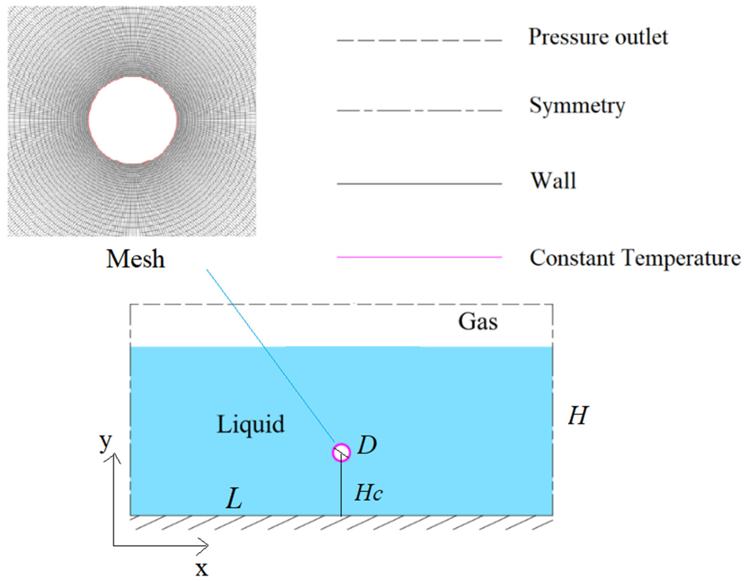
As shown in Figure 2, a cylinder heater is immersed horizontally in the liquid hydrogen pool of 18.324 K at atmosphere pressure. The heater surface is considered to be at a constant wall temperature of 80 K, the upper boundary of calculated region is the pressure outlet condition, and the sides of the liquid pool adopt symmetry boundary conditions. The two-dimensional model is divided into a fully structured grid and is encrypted near the surface of the cylinder heater, as shown in the figure. The diameter of the cylinder is changed from 0.2 to 30 mm, and the length of the liquid pool L is correspondingly set to 10 times the diameter of the cylinder.
2.2. Governing Equations
The volume-of-fluid (VOF) multiphase method is adopted, and the continuity equations for the volume fraction are
For each control cell, the volumes of liquid and vapor sum up to unity.
The volume fraction weighted average method is used to calculate the fluid properties in each cell.
The momentum equation can be written as Equation (5), which is solved throughout the whole domain and shared by the two phases.
The volume force is transformed from surface tension and added as a source term to the momentum equation. The continuum surface force (CSF) model proposed by Brackbill et al. [41] is chosen to express the surface tension.
where and are the surface curvatures.
The energy equation can be written as
The energy term E is computed as mass-averaged variables.
The effective thermal conductivity λeff is calculated as follows:
where cp is the specific heat, µt is the turbulent viscosity, and Prt represents the turbulent Prandtl number. The energy source term Sh is calculated as
Lee’s model is selected in this paper, and the mass transfer rate per unit volume is calculated according to the following relations:
where ri is the mass transfer intensity factor with the unit of s−1.
The upper boundary of the fluid is an open condition, described as follows:
The symmetry boundaries of the sides of the liquid pool are expressed as
The boundaries for the solid surface are described as
2.3. Turbulence Model
The combination of the model and the wall function is a common method for turbulence calculation in the heat transfer process for the good convergence rate as well as low memory requirements. The low-Re model proposed by Launder et al. [42] is a reasonable supplement to the model that improves the calculation of the nearby wall area by modifying the damping function and additional terms. Due to the high calculation accuracy for heat flux, the low-Re model is selected in this paper. The turbulent kinetic energy and the turbulent energy dissipation rate are calculated from the transport equations.
where the , and are the damping functions considering the effect of the turbulent Reynolds number Ret.
represents the generation of turbulent kinetic energy due to the mean velocity gradients, and represents the anisotropic dissipation effect of turbulent kinetic energy in the viscous sublayer.
The equation includes five adjustable constants , , , , and . The values in the simulation are as follows according to Launder et al. [42]:
2.4. Numerical Approaches
The numerical simulation in this paper selects the SIMPLE algorithm for the pressure and velocity equations based on pressure-based transient solver in commercial software Fluent. The second-order upwind scheme is used to discretize density, momentum, and energy equations; the geo-reconstruct scheme is chosen as volume fraction discretization; and the Green–Gauss Cell-Based and PRESTO schemes are applied for gradient and pressure discretization, respectively. The physical properties of the fluid are acquired according to Reference Fluid Properties Database (REFPROP). The time step is varied from 10−6 s to 10−4 s in the calculation process, and the convergence criterion of energy equation is 10−6.
3. Model Validation
3.1. Phase Change Verification
The key problem in the application of the Lee phase change model is to find the appropriate coefficient ri. The value of the mass transfer intensity factor ri covers a wide range, from 0.1 to 107 s−1 [43,44,45]. The optimum value of the empirical coefficient ri is investigated by many studies, and the conclusions prove that a significantly low value of ri could lead to discrepancy and an excessively high value of ri would cause convergence problems. As shown in Figure 3, the optimum range of empirical coefficient ri in this numerical model is from 102 to 104.
3.2. Grid Independence
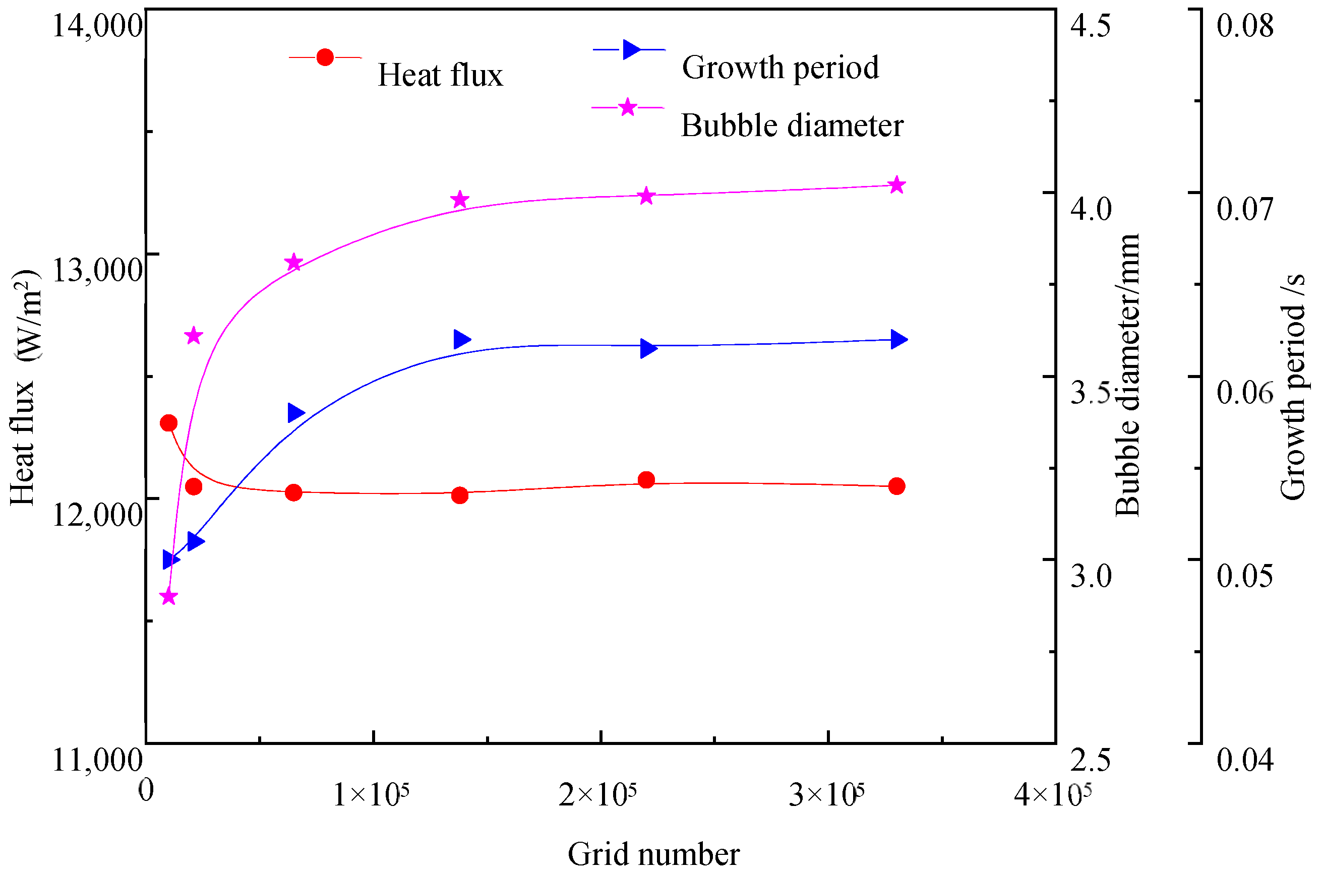
Since the low-Re turbulence model requires a good-quality mesh near the wall, the dimensionless parameters y+ will definitely be less than 1 during the grid independence verification. To ensure calculation accuracy, three parameters are selected as the criteria. It can be seen from Figure 4 that when y+ is less than 1, the heat flux is less affected by the number of grids, but for the bubble diameter and the growth period, the grid needs to be dense enough to achieve accuracy. In the case of comprehensive consideration of heat transfer and bubble behavior, 150,000 grids are considered to be suitable computational grids for this working condition.
3.3. Experimental Verification
Experimental verification is conducted with liquid hydrogen. The experimental data reported in Merte [46] are chosen as the verification condition, and the points in Figure 5 depict the boiling curve of hydrogen. The simulated results cover the film boiling section and agree well with the experimental data in terms of trend and value.
4. Results and Discussion
The simulation of film boiling over cylinders of various diameters is performed based on the above model, and the physical and thermal characteristics are analyzed carefully. For the film boiling, the heater is completely covered by the gas layer and heat conduction through the gas film is the main driving energy for the phase change, so the evolution of the liquid–vapor interface is critical to the heat transfer mechanism. Periodic growth of bubbles on the horizontal cylinder and their detachment from the cylinder are observed for various conditions, and the bubble detachment shapes are illustrated in Figure 6.
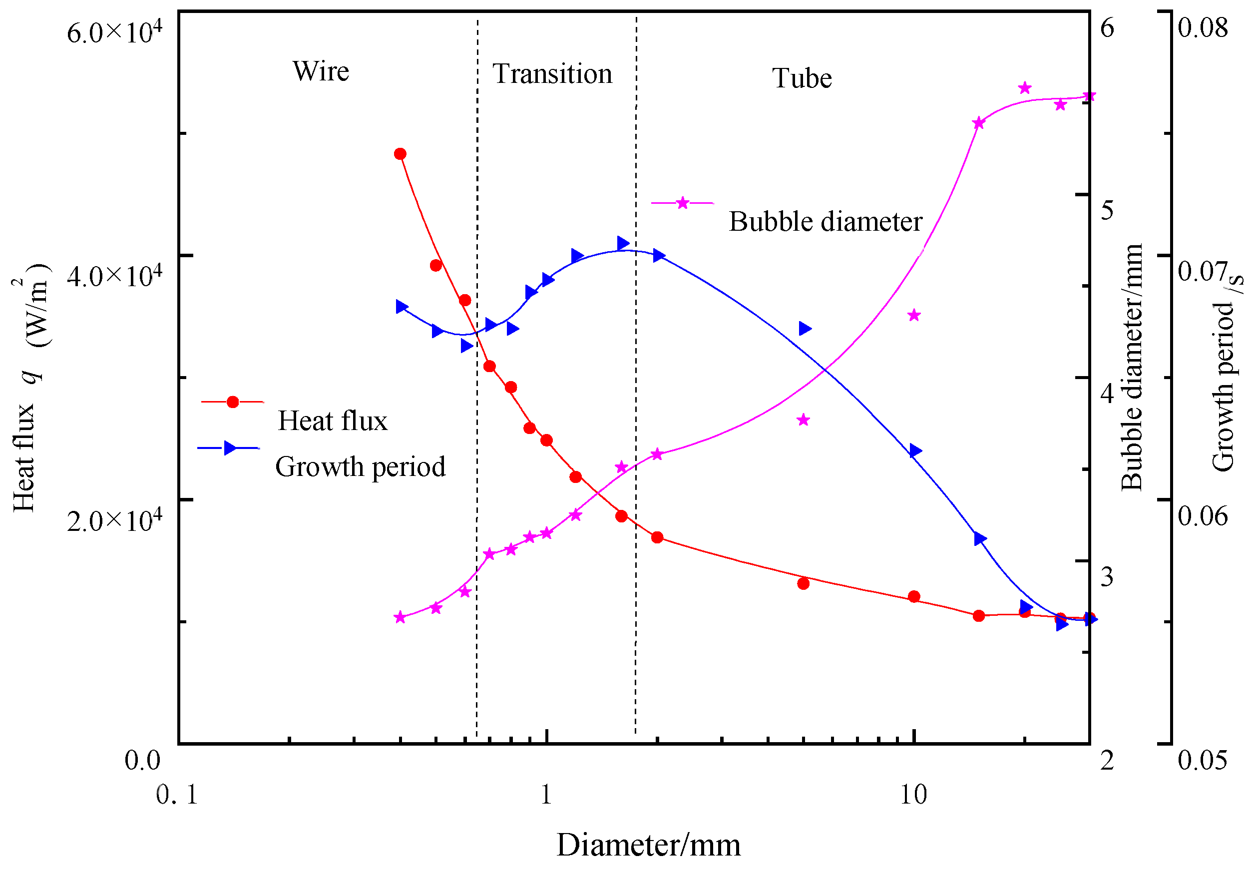
The time-averaged heat flux, the bubble detachment diameter, and the growth period for cylinders of various diameters are compared in Figure 7. As the diameter increases, the heat flux decreases and the bubble detachment diameter gradually increases. The bubble growth period shows a complicated law with the change in the diameter of the heating surface. According to the evolution of the liquid–vapor interface and the heat transfer performance, the cylinders in this paper are divided into three structures for analysis: wire heater, transition heater, and tube heater. As shown in Figure 7, the distinction between wire and transition is between 0.6 and 0.7 mm and the distinction between transition and tube is between 1.8 and 2 mm.
4.1. Film Boiling on a Wire Surface
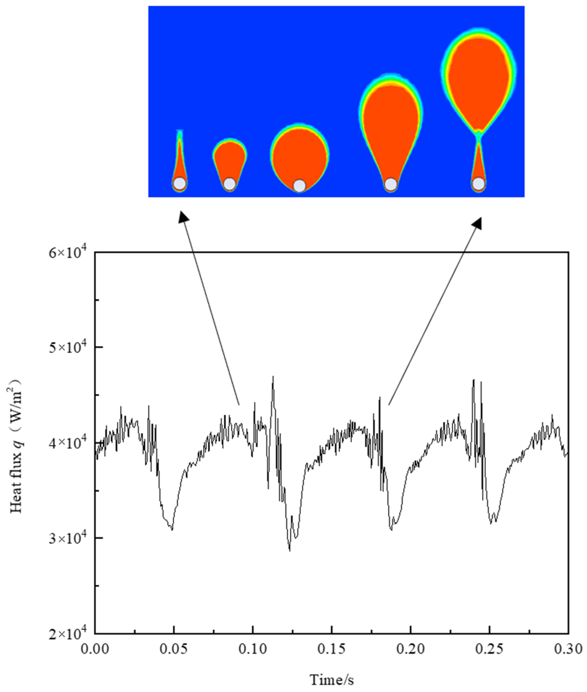
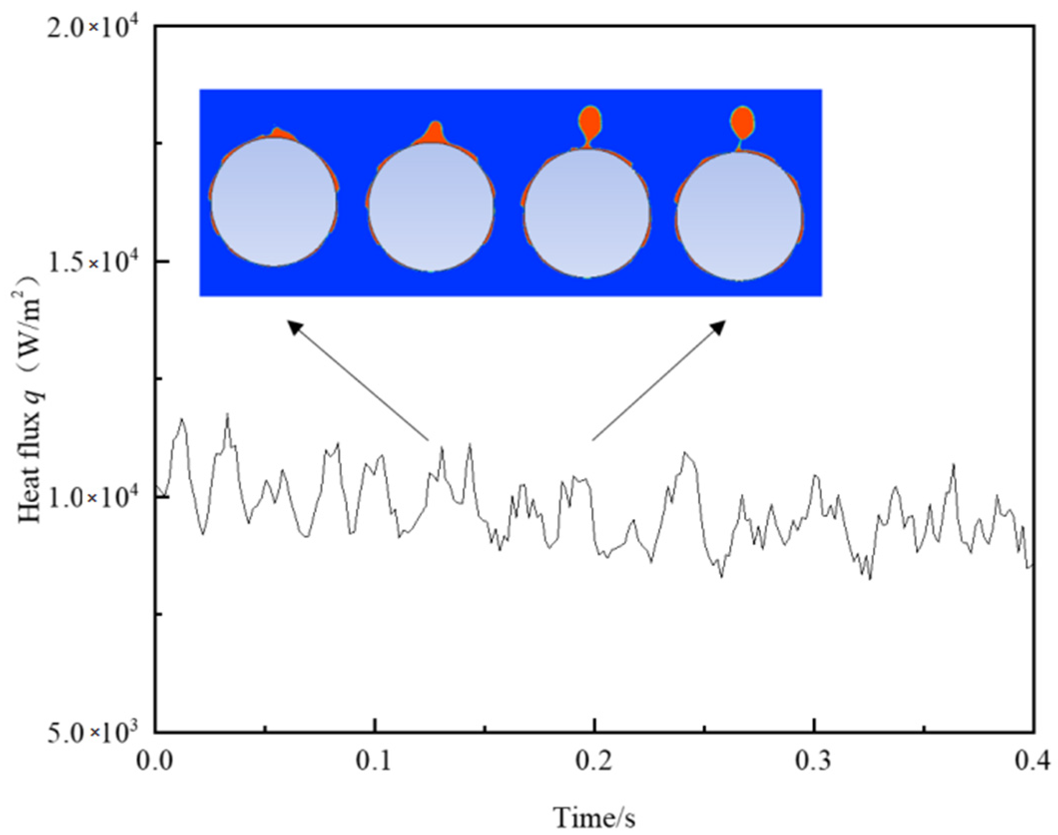
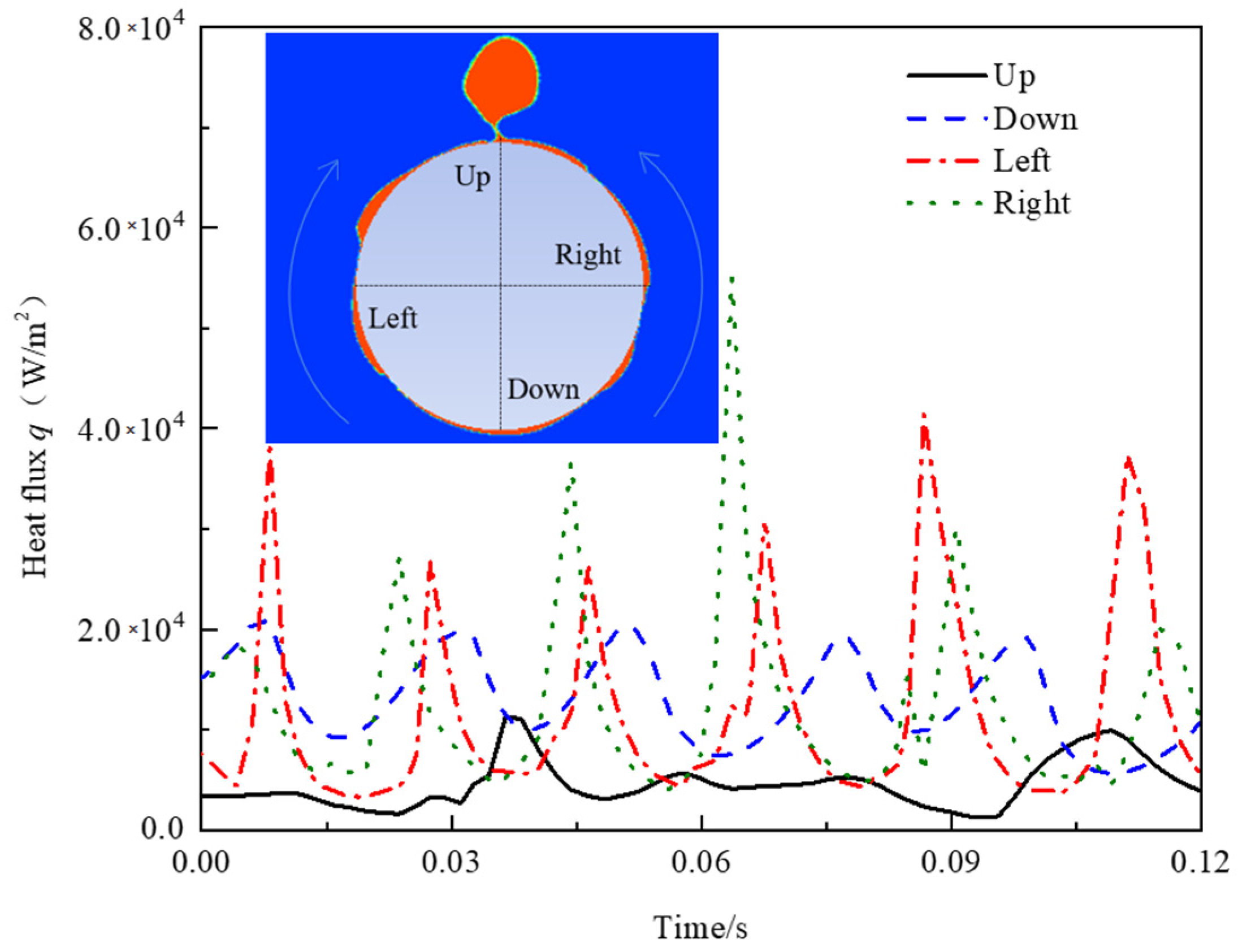
Figure 8 shows the evolution of bubbles and the spatial-averaged heat flux of film boiling over the surface of the 0.5 mm wire. It can be seen that the formation and departure of bubbles correspond to the typical heat flux change cycle. When the heating surface is covered by thick gas film, the average heat flow decreases due to the increase in thermal resistance. Once the gas accumulated on the upper part of the wire under a buoyancy effect begins to form a bubble shape, the gas film covering the surface of the wire becomes thinner and the average heat flux gradually rises until the bubble leaves the wire. For a quantitative display, the heat flux at four typical positions on the wire surface over time is displayed in Figure 9. For the upper section, the heat flux remains low due to vapor accumulation for the whole process. The heat flux in the lower section of the wire changes periodically and the peak heat flux can reach the bottom of the wire. The heat flux on both left and right sides is exactly the same and also fluctuates periodically as the bubble evolves.
Because it is a small-diameter wire, the physical behavior as well as the heat transfer mechanism of the 0.2 mm wire shows a different pattern. Figure 10 displays the spatial-averaged heat flux and the evolution of the gas–liquid interface for a 0.2 mm wire heater. The wire is wrapped by gas film, and the spatial-averaged heat flux keeps stable during the whole film boiling process. The heat flux at four typical positions is illustrated in Figure 11. It is noted that the heat flux at the bottom of the wire is higher than at the other three positions under the buoyancy effect. This phenomenon can be explained by the energy balance at the phase interface. For the small-diameter wire heater, the heat conducted through the vapor film is small and can be totally eliminated by the condensation effect driven by subcooled bulk liquid, so the gas cannot accumulate enough to form bubbles.
4.2. Film Boiling on the Tube Surface
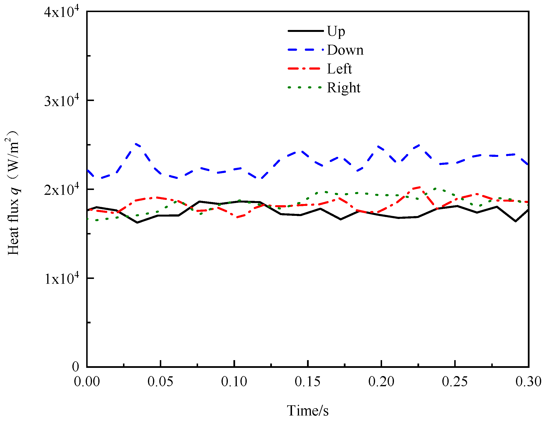
Figure 12 shows the evolution of bubbles and the spatial-averaged heat flux of film boiling over the surface of the 25 mm wire. Compared with the wire surface, the heat flux fluctuation of the tube surface is smaller and its fluctuation law does not correspond to the periodic growth of bubbles. Several crescent-shaped gas structures move slowly upward on both sides of the tube and accumulate at the top to form bubbles. Figure 13 displays the heat flux at four typical positions on the 25 mm tube surface over time. The peak heat flux happens on the left or the right, which exhibits periodic fluctuations with the movement of the crescent-shaped gas structure. The heat flux at the bottom of the tube also fluctuates cyclically, but the amplitude is smaller than that on both sides. Similar to the wire structure, the heat flux on top is the smallest and reaches a maximum when the bubble leaves.
4.3. Analysis of Heater Diameter
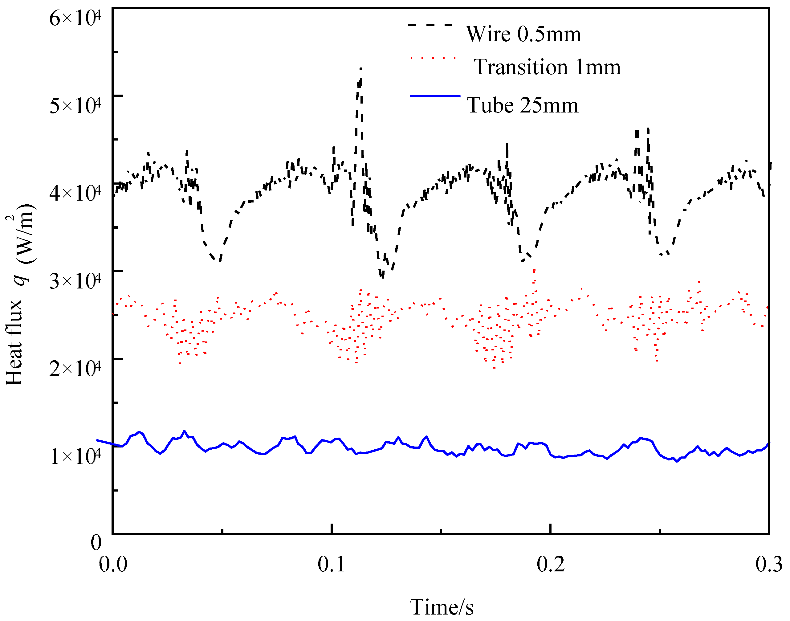
The spatial-averaged heat flux comparison of three typical diameter heating surfaces (0.5 mm wire, 1 mm transition, and 25 mm tube) is shown in Figure 14. It is obvious that the fluctuation amplitude and the average value of heat flux decrease with an increase in diameter. There are similarities as well as differences between the small-diameter cylinder heater and the large-diameter cylinder heater. Combined with the above analysis, the heat transfer of the wire is affected by the evolution of a single bubble, while the heat transfer of the tube is mainly affected by the movement of multiple crescent-shaped gas structures along the surface.
For the horizontal plate heating structure, the gas–liquid interface in the pool film boiling follows the Rayleigh–Taylor instability. The critical wavelength deduced from related instability analysis is a significant length scale for the bubble departure diameter. The release of the bubble is mainly affected by gravity and surface tension. Therefore, if the influence of the heating surface structure is excluded, the bubble departure diameter becomes a constant parameter.
For tube heaters, the time-averaged heat flux, the bubble detachment diameter, and the growth period with various diameters are shown in Figure 15. As the diameter of the tube increases, the bubble detachment diameter gradually increases and the heat flux as well as the bubble growth period gradually decrease. There is an asymptotic value of the bubble detachment diameter with an increase in the tube diameter, which is a special feature of the tube heating surface.
For the wire heater, the thermal performance with various diameters is compared in Figure 16. There are two different gas–liquid interface patterns with the increase in the wire diameter. For the small-diameter wires, the heating surface is wrapped by thick gas film instead of the bubble evolution and the heat flux is small. For the large-diameter wires, the bubble diameter increases with the increase in the wire diameter and the bubble growth time decreases correspondingly. Poorer heat transfer performance is also observed as the diameter increases for the wire heating surface.
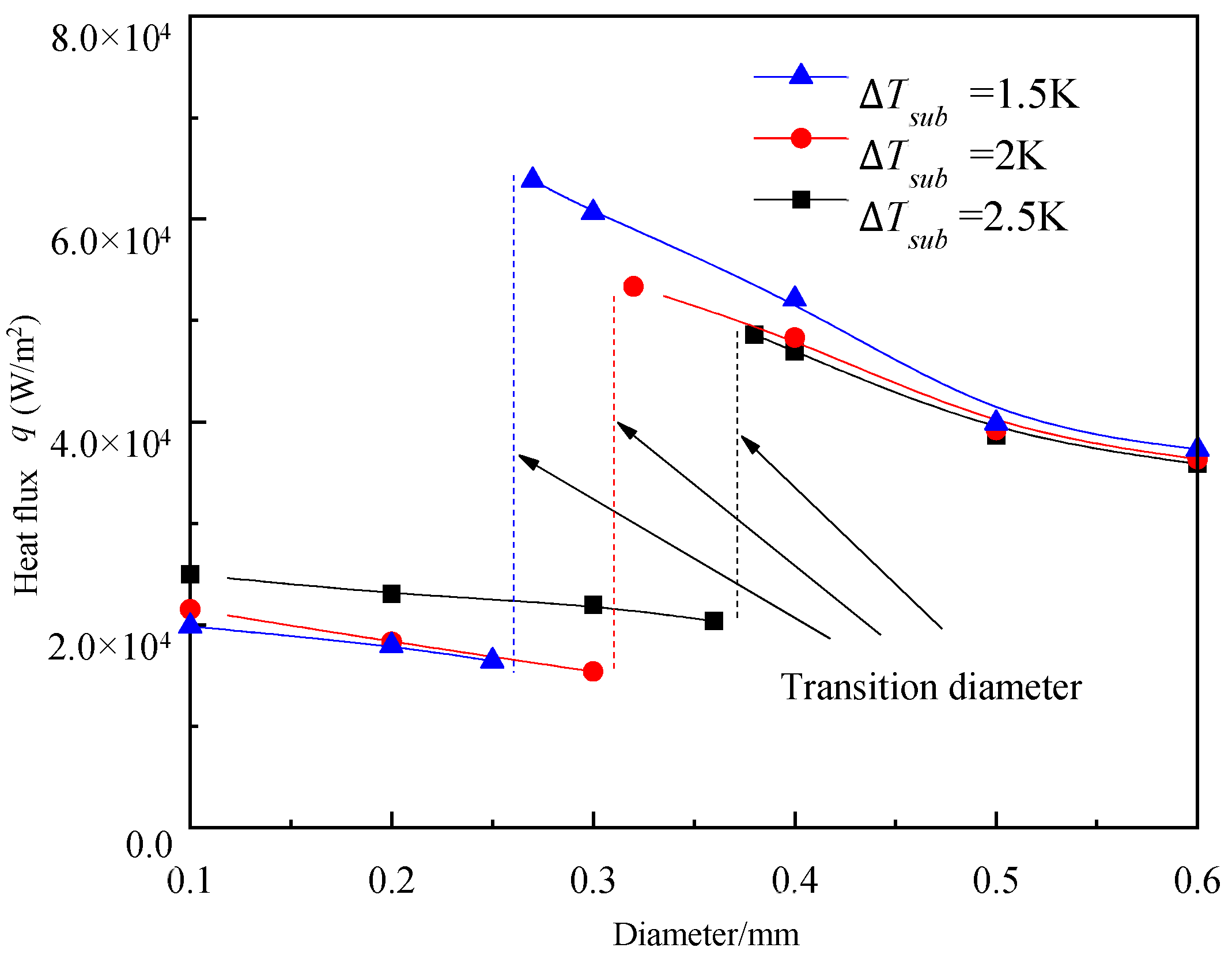
Figure 17 shows the gas–liquid interface pattern under different subcooling conditions for a 0.5 mm wire heater. It is shown that the bubble departure diameter decreases with an increase in the subcooling temperature. When the degree of subcooling exceeds a certain level, there is no bubble formation and departure. This is due to the fact that the enhanced condensation effect leads to a reduction in gas volume. When the condensing effect is large, the conduction heat through gas film can be removed totally, so a balance is reached and no bubble growth happens at the gas–liquid interface. Since the evolution of the liquid–gas interface has a direct effect on the heat transfer performance, the heat flux also experiences a sudden change phenomenon. Figure 18 displays the heat flux for the wire in different subcooling conditions. It is noted that the transition diameter increases with an increase in the subcooling degree. This is because for the larger subcooling liquid, more heat from the heating surface is required to balance the condensation effect.
5. Conclusions
The simulation of pool film boiling of hydrogen over a horizontal cylinder is performed, and the diameter of the horizontal cylinder ranges from 0.2 to 30 mm. The main conclusions are summarized as follows:
- (1)
- The diameter of the horizontal cylinder is a key factor affecting the thermal and physical performance of hydrogen pool film boiling. As the diameter increases, the bubble detachment diameter gradually increases, the heat flux decreases, and the bubble growth period experiences a complicated law.
- (2)
- For the wire heating surface, the heat flux is affected by the evolution of a single bubble and the formation and departure process of a bubble exactly corresponds to a typical cycle of heat flux change. Besides, the small-diameter wire is wrapped by gas film and the spatial-averaged heat flux keeps stable during the whole film boiling process.
- (3)
- For the tube heating surface, the heat transfer is mainly affected by the movement of multiple crescent-shaped gas structures along the surface and the heat flux fluctuation is smaller than that of the wire surface. When the diameter of the tube increases to a certain extent, the bubble detachment diameter, the heat flux, and the bubble growth period all reach stable values.
- (4)
- As the wire diameter increases, two different gas–liquid interface patterns are observed. The degree of subcooling and the diameter of the wire heater are two determining factors for the gas–liquid interface shape. In addition, the transition diameter of two different thermal performance patterns increases with the increase in the subcooling degree.
In conclusion, the results in this paper reveal the heat transfer behaviors of pool film boiling of hydrogen over horizontal cylinders, which provides a theoretical basis for engineering applications. When the degree of subcooling exceeds a certain level, no bubble growth happens at the gas–liquid interface and the heat flux is significantly small. The special characteristics of the thick gas film instead of the bubble evolution are analyzed and provide a possible point to avoid heat transfer deterioration.
Author Contributions
Software, J.W.; validation, L.W.; formal analysis, J.W.; writing—original draft preparation, J.W.; supervision, L.W.; project administration, Y.L.; funding acquisition, Y.L. All authors have read and agreed to the published version of the manuscript.
Funding
This work was supported by the National Natural Science Foundation of China (51876153, 51976151) and the Research Fund of State Key Laboratory of Technologies in Space Cryogenic Propellants (SKLTSCP202004). The China Scholarship Council (Grant No. 201906280355) is gratefully acknowledged.
Institutional Review Board Statement
Not applicable.
Informed Consent Statement
Not applicable.
Data Availability Statement
Not applicable.
Acknowledgments
The State Key Laboratory of Technologies in Space Cryogenic Propellants and China Scholarship Council are gratefully acknowledged.
Conflicts of Interest
The authors declare that they have no known competing financial interests or personal relationships that could have appeared to influence the work reported in this paper.
Nomenclature
| cp | Specific heat, J/(kg·K) |
| D | Diameter of cylinder, m |
| E | Internal energy, J/kg |
| Fvol | Volume force, N/m3 |
| g | Acceleration due to gravity, m/s2 |
| h | Enthalpy, J/kg |
| H | Height of hydrogen pool, m |
| Hc | Height of cylinder, mm |
| hfg | Latent heat, J/kg |
| L | Length of hydrogen pool, m |
| Nu | Nusselt number |
| p | Pressure, Pa |
| P0 | Atmospheric pressure, Pa |
| Pr | Prandtl number |
| Prt | Turbulent Prandtl number |
| q | Heat flux, W/m2 |
| Re | Reynolds number |
| S | Volume mass source, kg/(m3s) |
| Sh | Energy source term, J/(m3s) |
| t | Time, s |
| T | Temperature, K |
| ΔTsup | Wall superheat, TW-Tsat |
| ΔTsub | Liquid subcooling, Tsat-Tl |
| Greek symbols | |
| a | Void fraction |
| ε | Turbulence dissipation rate, m2/s3 |
| ρ | Density, kg/m3 |
| k | Surface curvature, 1/m |
| λ | Thermal conductivity, W/(mK) |
| The most dangerous wavelength, m | |
| μ | Dynamic viscosity, Pa·s |
| μt | Turbulent viscosity, Pa·s |
| v | Velocity, m·s −1 |
| γ | Enthalpy, J/kg |
| σ | Surface tension, N/m |
| Φ | Generic property |
| Subscripts | |
| eff | Effective |
| f | Fluid |
| g | Gas |
| l | Liquid |
| m | Mixture property |
| sat | Saturation property |
| sub | Subcooled property |
| sup | Superheat property |
| w | Wall |
References
- Nukiyama, S. The maximum and minimum values of the heat Q transmitted from metal to boiling water under atmospheric pressure. Int. J. Heat Mass Transf. 1966, 9, 1419–1433. [Google Scholar] [CrossRef]
- Wang, J.; Li, Y.; Wang, L.; Xia, S.; Ren, J.; Mao, H.; Xu, Y. Numerical investigation on subcooled pool film boiling of liquid hydrogen in different gravities. Int. J. Hydrog. Energy 2020, 46, 2646–2657. [Google Scholar] [CrossRef]
- Nelson, R.; Unal, C. A phenomenological model of the thermal hydraulics of convective boiling during the quenching of hot rod bundles Part I: Thermal hydraulic model. Nucl. Eng. Des. 1992, 136, 277–298. [Google Scholar] [CrossRef]
- Zhu, C.; Li, Y.; Tan, H. Numerical study on natural convection of liquid nitrogen used to cool the high-temperature supercon-ducting cable in a new combined energy transmission system. Cryogenics 2020, 109, 103101. [Google Scholar] [CrossRef]
- Bromley, L.A. Heat transfer in stable film boiling. Chem. Eng. Prog. 1950, 46, 221–227. [Google Scholar]
- Banchero, J.T.; Barker, G.E. Stable film boiling of liquid oxygen outside single horizontal tubes and wires. Chem. Eng. Prog. 1965, 51, 21. [Google Scholar]
- Breen, B.P.; Westwater, J.W. Effect of diameter of horizontal tubes on film boiling heat transfer. Chem. Eng. Prog. 1962, 58, 67–72. [Google Scholar]
- Flanigan, V.J. A Study of Film Boiling of Liquid Nitrogen and Liquid Argon Over a Wide Pressure Range with Cylindrical Heaters 1967. Master’s Thesis, University of Missouri, Columbia, MO, USA, 1967; p. 5171. Available online: https://scholarsmine.mst.edu/masters_theses/5171 (accessed on 14 December 2021).
- Capone, G.J.; Park, E.L. Estimation of Film-Boiling Heat Transfer Coefficients for Cylindrical Heaters in Corresponding-States Fluids; Springer: New York, NY, USA, 1995; pp. 283–285. [Google Scholar] [CrossRef]
- Lei, W.; Jiaojiao, W.; Tian, Y.; Xiaoning, H.; Fushou, X.; Yanzhong, L. Film boiling heat transfer prediction of liquid nitrogen from different geometry heaters. Int. J. Multiphas. Flow 2020, 156, 119854. [Google Scholar] [CrossRef]
- Gorenflo, D.; Baumhögger, E.; Windmann, T.; Herres, G. Nucleate pool boiling, film boiling and single-phase free convection at pressures up to the critical state. Part I: Integral heat transfer for horizontal copper cylinders. Int. J. Refrig. 2010, 33, 1229–1250. [Google Scholar] [CrossRef]
- Pomerantz, M.L. Film Boiling on a Horizontal Tube in Increased Gravity Fields. J. Heat Transf. 1964, 86, 213. [Google Scholar] [CrossRef]
- Sakurai, A.; Shiotsu, M.; Hata, K. Effect of System Pressure on Film-Boiling Heat Transfer, Minimum Heat Flux, and Minimum Temperature. Nucl. Sci. Eng. 1984, 88, 321–330. [Google Scholar] [CrossRef]
- Sakurai, A.; Shiotsu, M.; Hata, K. Effect of subcooling on film boiling heat transfer from horizontal cylinder in a pool of water. In Proceedings of the International Heat Transfer Conference 8, San Francisco, CA, USA, 17–22 August 1986. [Google Scholar] [CrossRef]
- Sakurai, A.; Shiotsu, M.; Hata, K. A General Correlation for Pool Film Boiling Heat Transfer From a Horizontal Cylinder to Subcooled Liquid: Part 1—A Theoretical Pool Film Boiling Heat Transfer Model Including Radiation Contributions and Its Analytical Solution. J. Heat Transf. 1990, 112, 430–440. [Google Scholar] [CrossRef]
- Sakurai, A.; Shiotsu, M.; Hata, K. A general correlation for pool film boiling heat transfer from a horizontal cylinder to subcooled liquid:Part2-Experimental data for various liquids and its correlation. J. Heat Transf. 1990, 112, 836–845. [Google Scholar] [CrossRef]
- Sarma, P.K.; Rao, V.D.; Bergles, A.E. Turbulent film boiling on a horizontal cylinder—effect of temperature dependent properties. Energ. Convers. Manag. 1997, 38, 1135–1144. [Google Scholar] [CrossRef]
- Sarma, P.K.; Subrahmanyam, T.; Rao, V.D.; Bergles, A.E. Turbulent film boiling on a horizontal cylinder. Int. J. Heat Mass Transf. 2001, 44, 207–214. [Google Scholar] [CrossRef]
- Frederking, T.H.K.; Clark, J.A. Natural Convection Film Boiling on a Sphere; Springer: Boston, MA, USA, 1963; pp. 501–506. [Google Scholar]
- Simoneau, R.J.; Baumeister, K.J. Experimental Effects of Pressure, Subcooling, and Diameter on Thin-Wire Film Boiling of Liquid Nitrogen; Springer: Berlin/Heidelberg, Germany, 1971. [Google Scholar]
- Horie, Y.; Shirai, Y.; Shiotsu, M.; Matsuzawa, T.; Yoneda, K.; Shigeta, H.; Tatsumoto, H.; Hata, K.; Naruo, Y.; Kobayashi, H.; et al. Film Boiling Heat Transfer Properties of Liquid Hydrogen in Natural Convection. Phys. Procedia 2015, 67, 643–648. [Google Scholar] [CrossRef] [Green Version]
- Rousselet, Y.; Warrier, G.R.; Dhir, V.K. Subcooled pool film boiling heat transfer from small horizontal cylinders at near-critical pressures. Int. J. Heat Mass Transf. 2014, 72, 531–543. [Google Scholar] [CrossRef]
- Ede, A.J.; Siviour, J.B. Sub-cooled film boiling on horizontal cylinders. Int. J. Heat Mass Transf. 1975, 18, 737–742. [Google Scholar] [CrossRef]
- Son, G.; Dhir, V.K. Numerical Simulation of Saturated Film Boiling on a Horizontal Surface. J. Heat Transf. 1997, 119, 525–533. [Google Scholar] [CrossRef]
- Juric, D.; Tryggvason, G. Computations of boiling flows. Int. J. Multiph. Flow 1998, 24, 387–410. [Google Scholar] [CrossRef]
- Esmaeeli, A.; Tryggvason, G. Computations of film boiling. Part I: Numerical method. Int. J. Heat Mass Transf. 2004, 47, 5451–5461. [Google Scholar] [CrossRef]
- Esmaeeli, A.; Tryggvason, G. Computations of film boiling. Part II: Multi-mode film boiling. Int. J. Heat Mass Transf. 2004, 47, 5463–5476. [Google Scholar] [CrossRef]
- Son, G.; Dhir, V.K. Numerical simulation of film boiling near critical pressures with a level set method. J. Heat Transfer 1998, 120, 183–192. [Google Scholar] [CrossRef]
- Liu, Z.; Wang, L.; Jin, Y.; Li, Y. Development of thermal stratification in a rotating cryogenic liquid hydrogen tank. Int. J. Hydrog. Energy 2015, 40, 15067–15077. [Google Scholar] [CrossRef]
- Shao, X.; Pu, L.; Li, Q.; Li, Y. Numerical investigation of flammable cloud on liquid hydrogen spill under various weather conditions. Int. J. Hydrog. Energy 2018, 43, 5249–5260. [Google Scholar] [CrossRef]
- Qian, J.-Y.; Li, X.-J.; Gao, Z.-X.; Jin, Z.-J. A numerical study of unintended hydrogen release in a hydrogen refueling station. Int. J. Hydrog. Energy 2020, 45, 20142–20152. [Google Scholar] [CrossRef]
- Arevalo-Ramirez, R.; Antúnez, D.; Rebollo, L.; Abánades, A. Estimation of radiation coupling factors in film boiling around spheres by mean of Computational Fluid Dynamics (CFD) tools. Int. J. Heat Mass Transf. 2014, 78, 84–89. [Google Scholar] [CrossRef]
- Yuan, M.H.; Yang, Y.H.; Li, T.S.; Hu, Z.H. Numerical simulation of film boiling on a sphere with a volume of fluid interface tracking method. Int. J. Heat Mass Transf. 2008, 51, 1646–1657. [Google Scholar] [CrossRef]
- Ahammad, M.; Olewski, T.; Véchot, L.N.; Mannan, S. A CFD based model to predict film boiling heat transfer of cryogenic liquids. J. Loss Prev. Process. Ind. 2016, 44, 247–254. [Google Scholar] [CrossRef]
- Saha, A.; Das, A.K. Numerical study of boiling around wires and influence of active or passive neighbours on vapour film dy-namics. Int. J. Heat Mass Transf. 2018, 130, 440–454. [Google Scholar] [CrossRef]
- Tomar, G.; Biswas, G.; Sharma, A.; Agrawal, A. Numerical simulation of bubble growth in film boiling using a coupled level-set and volume-of-fluid method. Phys. Fluids 2005, 17, 112103. [Google Scholar] [CrossRef]
- Ningegowda, B.M.; Premachandran, B. Numerical investigation of the pool film boiling of water and R134a over a horizontal surface at near-critical conditions. Numer. Heat Transf. Part A Appl. 2017, 71, 44–71. [Google Scholar] [CrossRef]
- Singh, N.K.; Premachandran, B. Numerical investigation of film boiling on a horizontal wavy wall. Int. J. Heat Mass Transf. 2020, 150, 119371. [Google Scholar] [CrossRef]
- Sadeghi, R.; Shadloo, M.S. Three-dimensional numerical investigation of film boiling by the lattice Boltzmann method. Numer. Heat Transf. Part A Appl. 2017, 71, 560–574. [Google Scholar] [CrossRef]
- Ma, X.; Cheng, P. 3D simulations of pool boiling above smooth horizontal heated surfaces by a phase-change lattice Boltzmann method. Int. J. Heat Mass Transf. 2018, 131, 1095–1108. [Google Scholar] [CrossRef]
- Brackbill, J.U.; Kothe, D.B.; Zemach, C. A continuum method for modeling surface tension. J. Comput. Phys. 1992, 100, 335–354. [Google Scholar] [CrossRef]
- Launder, B.E.; Sharma, B.I. Application of Energy Dissipation Model of Turbulence to the Calculation of Flow Near Spinning Disc. Lett. Heat Mass Transf. 1974, 1, 131–137. [Google Scholar] [CrossRef]
- Kharangate, C.; Mudawar, I. Review of computational studies on boiling and condensation. Int. J. Heat Mass Transf. 2017, 108, 1164–1196. [Google Scholar] [CrossRef]
- Ma, Y.; Li, Y.; Zhu, K.; Wang, Y.; Wang, L.; Tan, H. Investigation on no-vent filling process of liquid hydrogen tank under microgravity condition. Int. J. Hydrog. Energy 2017, 42, 8264–8277. [Google Scholar] [CrossRef]
- Liu, Z.; Li, Y.; Zhou, G. Study on thermal stratification in liquid hydrogen tank under different gravity levels. Int. J. Hydrog. Energy 2018, 43, 9369–9378. [Google Scholar] [CrossRef]
- Merte, H. Incipient and Steady Boiling of Liquid Nitrogen and Liquid Hydrogen under Reduced Gravity; Technical Report No. 7, NASA CR-103047; The University of Michigan: Ann Arbor, MI, USA, 1970. [Google Scholar]
Figure 1.
Nukiyama curve of pool boiling heat transfer.

Figure 2.
The geometric diagram and boundary conditions (Adapted from Ref. [2]).
Figure 2.
The geometric diagram and boundary conditions (Adapted from Ref. [2]).

Figure 3.
The calculated heat flux with different ri values (Adapted from Ref. [2]).
Figure 3.
The calculated heat flux with different ri values (Adapted from Ref. [2]).

Figure 4.
The results with different grid numbers.

Figure 5.
The comparison of calculated results and experimental data [46].
Figure 5.
The comparison of calculated results and experimental data [46].

Figure 6.
Bubble detachment shapes for various cylindrical diameters.

Figure 7.
The thermal performance with different cylinder diameters.

Figure 8.
The spatial-averaged heat flux and the evolution of bubbles for the 0.5 mm wire.

Figure 9.
The heat flux at four typical positions of the 0.5 mm wire heater during film boiling.

Figure 10.
The spatial-averaged heat flux and the evolution of the gas–liquid interface for the 0.2 mm wire.
Figure 10.
The spatial-averaged heat flux and the evolution of the gas–liquid interface for the 0.2 mm wire.

Figure 11.
The heat flux at four typical position of the 0.2 mm wire heater during film boiling.

Figure 12.
The spatial-averaged heat flux and the evolution of the gas–liquid interface for the 25 mm tube.
Figure 12.
The spatial-averaged heat flux and the evolution of the gas–liquid interface for the 25 mm tube.

Figure 13.
The heat flux at four typical positions of the 25 mm tube heater during film boiling.

Figure 14.
The spatial-averaged heat flux of horizontal cylinders with different diameters.

Figure 15.
The thermal performance for the tube heating surface.

Figure 16.
The thermal performance for the wire heating surface.

Figure 17.
Bubble departure diameter for 0.5 mm wire heaters with different subcooling degrees.

Figure 18.
The time-averaged heat flux for a wire with different subcooling degrees.

Publisher’s Note: MDPI stays neutral with regard to jurisdictional claims in published maps and institutional affiliations. |
© 2022 by the authors. Licensee MDPI, Basel, Switzerland. This article is an open access article distributed under the terms and conditions of the Creative Commons Attribution (CC BY) license (https://creativecommons.org/licenses/by/4.0/).
Share and Cite
MDPI and ACS Style
Wang, J.; Li, Y.; Wang, L. Numerical Study on Pool Film Boiling of Liquid Hydrogen over Horizontal Cylinders. Energies 2022, 15, 1044. https://0-doi-org.brum.beds.ac.uk/10.3390/en15031044
AMA Style
Wang J, Li Y, Wang L. Numerical Study on Pool Film Boiling of Liquid Hydrogen over Horizontal Cylinders. Energies. 2022; 15(3):1044. https://0-doi-org.brum.beds.ac.uk/10.3390/en15031044
Chicago/Turabian StyleWang, Jiaojiao, Yanzhong Li, and Lei Wang. 2022. "Numerical Study on Pool Film Boiling of Liquid Hydrogen over Horizontal Cylinders" Energies 15, no. 3: 1044. https://0-doi-org.brum.beds.ac.uk/10.3390/en15031044
Note that from the first issue of 2016, this journal uses article numbers instead of page numbers. See further details here.