Article

Effect of Rotor Bars Shape on the Single-Phase Induction Motors Performance: An Analysis toward Their Efficiency Improvement

by
Ioannis D. Chasiotis
1,
Yannis L. Karnavas
1,* and
Franck Scuiller
2
1
Electrical Machines Laboratory, Department of Electrical and Computer Engineering, Democritus University of Thrace, 671 00 Xanthi, Greece
2
Naval Academy Research Institute, Ecole Navale, CC 600, CEDEX 9, F-29240 Brest, France
*
Author to whom correspondence should be addressed.
Submission received: 9 December 2021 / Revised: 4 January 2022 / Accepted: 11 January 2022 / Published: 19 January 2022
(This article belongs to the Special Issue Control, Operation and Protection of Multiphase Machines and Drives)

Abstract

:
Mandatory regulations are published worldwide for the efficiency of line-operated electric motors. The small-sized single-phase induction motors (SPIMs) will not be off the hook in terms of efficiency, since new regulations are scheduled to be introduced regarding them no later than July 2023. By doing so, the efficiency of capacitor-run SPIMs will be forced to exceed the (currently) typical ratings and comply with the requirements of the IE3 (i.e., premium) efficiency class. Since this task is challenging, the already published research works investigated several design, control, and manufacturing aspects. Nevertheless, less attention has been devoted to the study of the rotor bar’s shape impact, both on the SPIMs’ efficiency and starting capability. This gap is filled in this work by examining rotor squirrel-cage configurations with eight different bar shapes for the case of a four-pole/1.0 HP capacitor-run SPIM. A sensitivity analysis, which involves the simultaneous variation of the bar’s cross-sectional area, run-capacitor value, and auxiliary to main winding turns ratio, is performed. The motor’s electromagnetic behavior is estimated through finite element analysis. Through the acquired results, useful directions toward the SPIMs’ efficiency enhancement are provided, while simultaneously conclusions—not found elsewhere—are drawn concerning performance quantities, such as the motor’s starting current, currents shift angle, particular losses, breakdown torque, etc.

1. Introduction

The single-phase induction motors (SPIMs) hold a considerable share of the global electrical machines market, as they are utilized in an impressive number of applications (e.g., power tools, compressors, vacuum cleaners, conveyor belts, sewing and washing machines, grinders, refrigerators, food mixers, microwave ovens, air conditioners, hair and grain dryers, heating-circulating pumps, fans, centrifugal pumps, etc.) [1]. Their rated output power ranges from sub-fractional up to few kilowatts, and they are available in different configurations, depending upon the method for making them self-starting motors. They can be met in the following five types: (a) split-phase, (b) shaded poles, (c) capacitor-start/induction-run, (d) capacitor-start/capacitor-run, and (e) capacitor-run SPIMs. The starting mechanism is necessary, since the applied single-phase current creates only a pulsating magnetic field. So, even if the rotor is energized due to induction, the torque needed for the motor’s rotation is not developed. This will make the rotor vibrate but not to rotate. When the SPIMs are put into operation through the starting mechanism and by means of a rotating magnetic field, their rotor continues to rotate.
Among the aforementioned topologies, the capacitor-run SPIM gains great popularity, as it has important advantages (e.g., simple structure, increased robustness, lower starting current, high power factor over a wide speed and load range, etc.) over the other SPIM types [2]. The structure of this motor is quite similar to that of a three-phase squirrel-cage induction motor (IM). The major difference is related to the arrangement of the stator’s main and auxiliary winding. These windings are phase-shifted spatially by 90 electrical degrees. At the same time, a permanent capacitor is connected in series with the auxiliary winding during both the motor’s starting and running operation. The lap (either single- or double-layered) and the double-layer first-class sinusoidal winding layouts are the most common choices. The SPIM’s stator and rotor cores are manufactured of thin laminations of electrical steels. The low-carbon or silicon steels are mostly used, since the low cost is the main priority at the SPIMs’ mass production. Regarding the rotor’s squirrel-cage, it is made of a conductive alloy through die casting. This process permits the bars to be connected directly to the end-rings, and it has been established as the most cost-effective solution for bulk manufacturing of IMs squirrel-cages [3]. The squirrel-cage conductive material can be either aluminum or copper. The aluminum is more frequently selected at the construction of small SPIMs due to its low cost, while it allows better flexibility in the bar’s shape [4]. The replacement of aluminum with copper improves the motor’s efficiency but deteriorates its starting torque, as the copper’s electrical conductivity is much higher. The die-casting magnesium alloys are an attractive alternative as mentioned in [5], especially for applications that demand a high starting torque. For the rotor bars design, various geometries of semi-closed, closed, or open slots have been proposed in order to find out which one benefits the motor’s operational characteristics. The bar designs are classified into four types (design classes) based on the directions provided by the National Electrical Manufacturers Association (NEMA). Each one of them results in a different motor’s torque–slip curve and affects substantially the machine’s running performance and starting capability.
The capacitor-run SPIM’s starting torque and efficiency are quite low. The starting torque of commercial SPIMs is usually equal to 30–70% of its nominal one, while their efficiency barely exceeds 78% (even for motors with output power equal to or higher than 1.0 HP). The high efficiency of these machines was not—until recently—a strict requirement, as they are employed at low-power applications. Their horsepower ranges from 0.25 up to 1.5 HP. Most of them are designed so as to deliver the nominal torque at the lowest cost and fulfill the maximum temperature limit. However, a large number of them are produced daily. Additionally, recent research works highlighted that if their efficiency could be enhanced beyond the typical ratings, significant savings would be achieved [6].
Nowadays, mandatory regulations have been adopted worldwide aiming to accelerate the motors market transformation toward IE3 (premium) and IE4 (super premium) efficiency classes [7]. The IEC/EN 60034-30-1 standard (published by the International Electrotechnical Commission (IEC) in March 2014) defines the four efficiency classes for the line-operated single-speed motors. This standard includes both the single-phase and three-phase squirrel-cage IMs with two, four, six, and eight poles. Moreover, it covers a wide scope of products, as motors with rated output power from 0.12 up to 1000 kW and supply voltage from 50 V up to 1 kV are involved. According to the latest relevant European Union legislation, the efficiency of the three-phase medium-sized IMs (i.e., with output power in the range of 0.75–375 kW) must meet the IE3 ratings since January 2017 [8]. Very recently, i.e., since July 2021, the premium efficiency is also mandatory for the large-sized three-phase IMs (i.e., with rated output power in the range of 375–1000 kW), expanding even more the scope of motors. In the same year, a new regulation was introduced with respect to the small motors whose rated output power is equal to or above 0.12 kW and below 0.75 kW. The efficiency of the above motors will have to reach the IE2 level and move toward IE3 in the forthcoming years, as a revised version of the regulation is expected to be released. A similar regulation is scheduled to be introduced concerning the small-sized SPIMs no later than July 2023 [9]. By that time, it is believed that (a) the quantitative evaluation of the energy savings, achieved by amending the efficiency standards for small electric motors will be completed, and (b) it will be clarified whether such standards would be technologically feasible and economically justified. In the United States of America, the NEMA published new efficiency standards, too. Since 2010, the general-purpose line-fed electric motors from 1 to 200 HP have to satisfy the minimum requirements of NEMA Premium Efficiency. In June 2016, the scope of motors was expanded once again with the “Integral Horsepower Motor Rule”. Under this rule, all the single-speed IMs have to comply with the NEMA Premium Efficiency level. The smaller motors were not off the hook in terms of efficiency. Specifically, the Department of Energy (DOE) adopted an energy-efficiency standard, namely “Small Motor Rule”, for fractional horsepower IMs [10]. This standard includes both single-phase and three-phase IMs with (a) horsepower from 0.25 up to 3.0 HP and (b) two, four, and six poles. This rule is applied to SPIMs that incorporate either a capacitor during the start-up phase or capacitor(s) during both the start-up phase and running operation. The minimum efficiency values, set by this standard, are close or even equal to those imposed by the IE3 efficiency class. It can be said that the efficiency of the SPIMs will be forced to exceed IE2 and move toward the IE3 class sooner than expected [11].
In Figure 1, the international efficiency classes are depicted as a function of motor’s output power for a four-pole IM. It is apparent that the minimum efficiency requirements are greatly increased. As an example, the minimum efficiency that a four-pole/1.0 HP IM has to exhibit is much higher than the typical efficiency ratings (64% up to 78%) of the commercial capacitor-run SPIMs with the same specifications. Therefore, the development of SPIMs with enhanced efficiency is a challenging task for both designers and manufacturers and is gathering growing research and industrial interest.
In order to improve the SPIMs’ efficiency, so far, research efforts have focused on (a) the introduction of more accurate magnetic and thermal models for the better estimation of the motor’s electromagnetic and thermal behavior [13,14], (b) the optimal rotor squirrel-cage design [15,16,17], (c) the proper selection of the rotor bars/stator slots combination for a given number of poles [18], (d) the utilization of manufacturing techniques such as the skewing and inclination of rotor bars [19], (e) the appropriate choice of run-capacitor features (i.e., its optimal value and placement) [20,21], (f) the proposal of novel topologies [22], (g) the testing of advanced electrical steels and conductive alloys for the motor’s cores and squirrel-cage, respectively [23,24], and (h) the application of new casting methods [25]. Since most of the above solutions are not easily applicable to mass production, it is essential to have design approaches that provoke slight modifications of the existing SPIMs production procedure, and thus, they have a minimal impact on manufacturers. In this way, it will be much easier for them to design and construct new motors with higher efficiency at reasonable turn-around time [26,27]. A complete design methodology, which has been proven to be effective for a variety of capacitor-run SPIMs with different output power ratings and requirements, was presented in [28], which is an author’s previous research work. The preliminary findings of [29] were also exploited in that work. Although the suggested design strategy cannot be considered as a no-tooling-cost process as the manufacturers will not avoid the electromagnetic re-design of entire machine series, it relies on low-cost solutions/modifications. These solutions are: (a) the employment of low-loss magnetic materials for the motor’s cores, (b) the axial lengthening of the stator and rotor cores, (c) the usage of the double-layer first-class sinusoidal winding instead of the lap one, (d) the proper determination of the auxiliary winding parameters (i.e., number of turns and run-capacitor value), and (e) the design of rotor bars and end-rings by following the provided directions. The efficiency of the obtained SPIMs was found to be much higher than the typical values that are met at the commercial motors. So, important energy savings were recorded, while simultaneously, the SPIMs were advantageous from a manufacturing and economic point of view compared to the motors that derive from the classical design approach (described in [30]). It is to be noted that the new efficiency levels are achievable with the present technology and also by taking into consideration the standardized frame sizes.

2. Motivation and Contribution of the Work

However, the investigations that were conducted in [28] refer to capacitor-run SPIMs that have a squirrel-cage rotor with semi-closed slots of trapezoidal cross-section. The specific rotor bar geometry is commonly preferred by IM designers and manufacturers. Notwithstanding that, there are plenty of other alternatives regarding the bar’s shape that are used at commercial SPIMs. The impact of the bar’s shape on numerous motor’s performance quantities has been studied partially in already published research works that deal with the design of machines that have a squirrel-cage rotor, such as the three-phase IMs, the line-start permanent magnet synchronous motors (LPMSMs), and the line-start synchronous reluctance motors. For instance, inverter-fed high-speed three-phase IMs with semi-closed and closed rotor bars of different shape were designed, analyzed, and compared to each other in [31]. Few useful observations were drawn in [32] for the same motor type by taking the voltage unbalance effect into account. Furthermore, a comparison among various bar structures was made in [33] for an IM with rotor core made of amorphous material. The impact of the bar’s geometry on the efficiency, power factor, and torque ripple was studied in [34,35], by analyzing the IM’s operation under both healthy and faulty (i.e., with broken rotor bar(s)) conditions. In [36], the trade-off among the machine’s operational characteristics and their correlation with the geometrical parameters was discussed. A systematic approach to perform the design optimization of a squirrel-cage IM by focusing on the rotor slot configuration was proposed in [37,38]. An adequate number of different squirrel-cage designs was investigated in [39,40], where the transient performance of an LPMSM with copper squirrel-cage was considered. Rotor slots of different shape but with the same cross-sectional area were utilized in [41,42], too. A similar study was carried out in [43] for a line-start synchronous reluctance motor.
On the basis of the foregoing, it is clear that this research topic is not sufficiently addressed in the available literature regarding the SPIMs. Aiming to fill this gap, eight different rotor bar shapes (i.e., trapezoidal, oval, pent, polygonical, round, drop, rectangular, and quadrangular) are examined here for a four-pole/1.0 HP capacitor-run SPIM. The calculation of the machine’s basic dimensions and the rest of the geometrical parameters is conducted by applying the design methodology that was presented in [28]. The effect of the bar’s shape on the motor’s efficiency and power factor is highlighted with the help of a sensitivity analysis, which involves the simultaneous variation of (i) the bar’s cross-sectional area, (ii) the run-capacitor value, and (iii) the auxiliary to main winding turns ratio. The performance of each motor is estimated through the finite element analysis. The resulted SPIMs are compared with regard to the motor’s net mass, starting current, breakdown torque, and shift angle between the winding currents. The above features are of great importance for industrial motors, but less attention has been devoted to them in the relevant literature. So, useful conclusions—not found elsewhere—are extracted in this work. In addition, directions that could be valuable for designers and manufacturers toward the SPIMs’ efficiency enhancement are given. Last but not least, the generalization of the design approach (proposed in [28] by the authors) is evaluated.
The paper is organized as follows: in Section 3, the motor’s specifications and the applied constraints are described. Section 4 provides a thorough insight in significant aspects of the SPIMs design and analyzes the critical design parameters that will be set under investigation. The models employed for the SPIM’s performance determination are presented in Section 5. The acquired sensitivity analysis results along with the related discussion are given in Section 6. A detailed comparison of the SPIMs with the highest efficiency is made in Section 7. In Section 8, the impact of: (i) SPIM’s capacitance on the magnetizing reactance and magnetic saturation factor, (ii) skin effect on the rotor bars resistance and leakage reactance, and (iii) bar’s shape on the rotor ohmic losses is displayed and commented. Finally, Section 9 concludes the work.

3. Specifications of the SPIM under Study

The motor under study is a four-pole capacitor-run SPIM with 24 stator slots, 30 non-skewed rotor bars, and nominal output power equal to 746 W. Its desirable operational characteristics as well as its mounting type and insulation class are summarized in Table 1. All the considered specifications and constraints are in accordance with: (a) the latest international efficiency standards for electric motors and (b) the industrial trends. The information about the minimum requirements of the international efficiency classes for a four-pole IM at 50 Hz is tabulated in Table 2. The efficiency target has been set here so as to meet the minimum efficiency of IE3 efficiency class (i.e., η 82.5%). The rest of the performance quantities (e.g., starting to nominal torque ratio ( T s t / T n ), starting to nominal current ratio ( I s t / I n ), etc.) have been specified based on the data found in the commercial catalogues of SPIMs manufacturers. The strict constraints concerning the wire current density of the main and auxiliary winding ( J m and J a respectively) help to guarantee the following: (a) the motor’s satisfactory thermal behavior and (b) its operation under free-cooling conditions. According to the industrial standards and practices, the wire current density should be in the range of 3.1 A/mm 2 to 6.2 A/mm 2 for enclosed-type motors, while much higher values are acceptable for air-vented or open-frame constructions.
Regarding the motor’s design parameters, few of them have been chosen by exploiting the results of [29]. In particular, a structure with 24 stator slots has been preferred, since the efficiency and power factor of the SPIMs with the certain stator slots number ( Q s ) were found to be higher than the respective ones of the machines with Q s = 12 and Q s = 36 for given rotor bars number ( Q r ). The SPIM’s basic dimensions, airgap length, rotor diameters, as well as its stator slots, rotor bars, and end-ring geometrical characteristics have been calculated as described in [28]. Readers can refer to [28,29] in order to find more information about the electromagnetic features and other quantities (i.e., coefficients, factors, constants, etc.) that are included in the capacitor-run SPIM design process. A semi-closed geometry with trapezoidal shape has been selected for the stator slots, as it can be seen from Figure 2a. Since both sides of the airgap have slot openings (a semi-closed rotor slot has been also chosen), the Carter coefficients for the stator and rotor slotting ( k c s and k c r respectively) have been determined. The effective airgap length ( g e ) has been found by multiplying the actual airgap length (g) with the product of the two above Carter coefficients. The motor’s inner ( D s ) and outer ( D o ) diameters are equal to 83.41 mm and 138.87 mm, respectively. Its axial effective length (L) is equal to 125 mm, and it is larger than the D o . Topologies with axial length higher than their outer diameter derive (see Figure 2b) when the design methodology of [28] is used. The axial length is now increased by 32.6% compared to the corresponding one obtained when the classical design approach of [30] is followed. The SPIM is designed to fit inside the IEC 90L/NEMA 145 frame. The cast copper alloy C81500 has been utilized for the rotor bars and end-rings, while the silicon steel M350-50A (grade designation in agreement with the DIN EN 10106 standard for cold rolled non-oriented electrical steel strips and sheets) is employed for the stator and rotor core of the machine. This steel with a lamination thickness of 0.5 mm exhibits at 50 Hz losses equal to 1.5 W/kg and 3.5 W/kg for operation at 1.0 T and 1.5 T, respectively.

4. Analysis of Important Aspects in SPIM Design

The capacitor-run SPIM design procedure consists of many steps and involves (among others) assumptions that have to be made by the designer. In this section, only the paramount decisions are explained. The first one refers to the determination of the rotor bar cross-sectional area ( A b a r ). This area is correlated with the stator slot area ( A s ) as per Equation (1), where k b a r is the rotor slot area factor. The k b a r value has prominent impact both on the SPIM’s efficiency and starting capability. Indeed, when its value is low, the cross-sectional area is small, and the rotor slot is shallow. Such a design is similar to the configuration of NEMA design class D. This makes the rotor squirrel-cage resistance high and benefits the starting torque. On the other hand, it affects negatively the efficiency due to the relatively high rotor copper losses. A much deeper and larger rotor bar derives when higher values are assigned to k b a r . In this case, the starting torque deteriorates, but the copper losses become lower. In general, the k b a r takes values between 0.35 and 0.60 for small-sized SPIMs, as recommended in [30]. Nonetheless, in [28], it was demonstrated that the above variation range of k b a r is not the suitable one for the development of capacitor-run SPIMs with premium efficiency. For this reason, an expanded variation range (i.e., 0.2–0.6) is examined here for eight different rotor bar designs. The bar’s geometry modification as a function of k b a r is illustrated in Figure 3.
A b a r = k b a r A s Q s Q r
The rotor squirrel-cage structure has the most essential impact (compared to the respective one of other characteristics) on the starting torque of three-phase IMs. This is not valid for the capacitor-run SPIMs, since the effect of the auxiliary winding features (i.e., turns number and run-capacitor value) have to be taken into consideration. The auxiliary winding turns number ( N a ) is obtained from Equation (2) for given main winding turns number ( N m ) and auxiliary to main winding turns ratio (a). The N m is estimated through Equation (3), where f is the frequency, 2p is the poles number, B g is the average airgap magnetic flux density, k d i s is the magnetic flux correction factor, E m is the induced voltage of the main winding, and k w m is the fundamental factor of the main winding. The turns ratio influences considerably the SPIM’s magnetomotive force and its overall performance. Its value lies between 1.0 and 2.0 in most cases, but values lower than 1.0 are also permissible, as pointed out in [28]. In [30], the turns ratio is proposed to be set equal to 1.5 as a starting point at the design process. Its final value has to enable the motor to deliver adequate torque at the start-up phase and exhibit the desirable efficiency under nominal operation. The decision about the turns ratio defines the run-capacitor value ( C r u n ). The turns ratio and the C r u n are interdependent, which is perceptible from Equation (4), where I n is the SPIM’s nominal line current and U n is the supply voltage.
N a = a N m
N m = 2 p E m 2 2 π k d i s B g D s L k w m f
C r u n = I n 2 π f U n a 2 + 1
All the above critical design parameters (i.e., k b a r , C r u n and a) are set here under thorough investigation. As already noted, the variation range of k b a r is 0.2–0.6 (with a step of 0.025) for the majority of the rotor bar topologies. Its maximum value is different for the bars of round, drop, and quadrangular shape. This makes their implementation feasible. The variation range of C r u n is 18–30 μ F, with a step of 1.0. The N m and the turns ratio are specified through the sensitivity analysis targeting the fulfillment of the set objective, i.e., the development of SPIMs with: (i) satisfactory starting capability (i.e., T s t / T n 0.35) and (ii) the highest possible efficiency under this condition. In the view of the foregoing, the total number of the examined models is equal to 153,945 (5 × 21,900 + 2 × 15,144 + 1 × 14,157). Specifically, when the SPIM has trapezoidal, rectangular, polygonical, pent, and oval rotor bars, 21,900 models were created and analyzed in each case. The corresponding number is equal to 15,144 for the motors with bars of round and drop shape, while 14,157 models with quadrangular bars were developed and analyzed.

5. SPIM Modeling and Finite Element Analysis

The capacitor-run SPIM’s electromagnetic behavior is determined through the conduction of voltage-driven time-stepping finite element analysis (FEA) simulations in a two-dimensional environment. Its performance under both nominal operation and locked-rotor condition is estimated by using ANSYS® Electromagnetics Suite Software, which enables the coupling between the motor’s magnetic circuit and the external electric circuit. The last one consists of the main and auxiliary winding, the run-capacitor, and the supply source. The machine is simulated as connected directly to the mains line-voltage of 230 V at 50 Hz. The SPIM’s currents’ signal, speed signal, torque signal, magnetic flux density distribution at the stator and rotor core, and current density distribution at the rotor bars are the outputs of the developed FEA model under the motor’s nominal operation. Its particular losses are specified by processing the extracted information. The models and/or the analytical equations that have been employed for the losses claculation are briefly described here. Under sinusoidal magnetic flux condition, the iron losses ( P i r o n ) of the motor’s stator and rotor core derive from Equation (5), which exploits the well-known Bertotti loss separation model. The P i r o n are divided into hysteresis ( P h ), classical eddy current ( P c ), and excess eddy current ( P e ) losses. The applied formula contains the fundamental frequency of the magnetic field (f), the magnetic flux amplitude ( B m ), the coefficients of hysteresis, classical eddy current, and excess eddy current losses ( k h , k c , and k e respectively) and the coefficient β , which is related to the hysteresis losses. All the above coefficients depend on the steel’s properties.
P i r o n = P h + P c + P e = k h f B m β + k c f 2 B m 2 + k e f 1.5 B m 1.5
The SPIM’s stator windings copper losses ( P s c l ) are obtained from Equation (6), where R m is the main winding resistance, R a is the auxiliary winding resistance, and I a , r m s and I m , r m s are the r m s currents of the main and auxiliary winding, respectively. The winding resistance varies with the temperature. Hence, the R m and R a are modified according to the considered temperature through Equation (7). At this expression, R 0 is the phase resistance at the reference temperature T r e f , s R is the slope of resistance-temperature characteristic (i.e., the temperature coefficient of resistance of the conductor), and T is the prevailing temperature. The oil-filled or paper capacitors, which are incorporated at the motor of this type, are not ideal (i.e., they do not exhibit only capacitance). They have imperfections within their materials that create resistance. This resistance is called equivalent series resistance ( R E S R ), and it is typically set equal to 1.0% of the capacitor reactance. For example, the R E S R of a run-capacitor of 4.5 uF at 50 Hz supply frequency is equal to 7.07 Ω . So, the capacitor losses ( P c a p ) are specified as per Equation (8).
P s c l = R a I a , r m s 2 + R m I m , r m s 2
R = R 0 1 + s R T T r e f
P c a p = R E S R I a , r m s 2
The rotor ohmic losses ( P r c l ) of the squirrel-cage bars are determined by utilizing Equation (9) and by considering: (i) the impact of the skin effect on the rotor bars and (ii) that the rotor bar currents have components only in the direction of the z-axis at the two-dimensional model. The quantities, incorporated in Equation (9), are the rotor bars number ( Q r ), the bar’s axial length ( l b a r ), the bar’s electrical conductivity ( σ b a r ), the current density of each element ( J z , i ), and the area of each element ( A i ) in which the bar is divided when the FEA is performed. Since the skin effect creates a non-uniform current density distribution, the AC copper losses of each rotor bar are calculated as the sum of the losses in each element. The mechanical losses include the frictional ( P f ) and the windage losses ( P w i n d ). The first one comes as a consequence of the bearings, and they are dependent on the lubricant, the shaft’s rotational speed, mass and friction coefficient, and the bearing’s type, diameter, and load. They are approximated through Equation (10), where ω m is the angular speed of the shaft, k b is the friction coefficient (it ranges typically from 0.08 up to 0.20), G is the gravitational acceleration constant, D b is the bearing inner diameter, and M r is the mass of the rotating components. The M r involves the mass of the rotor core, squirrel-cage, shaft, end plates, and bearing. The windage losses have two components, i.e., the losses in airgap and the losses at the rotor’s end surfaces. The losses in the airgap are represented by the first term of Equation (11), where k r is the rough coefficient (it ranges from 1.0 up to 1.4, for a smooth surface k r = 1), C f is the torque coefficient, ρ a i r is the air density, D r is the rotor’s outer diameter, and D s h a f t is the shaft diameter. The C f is decided by the Couette Reynolds number ( R e ). The R e is given in Equation (12), where μ a i r is the dynamic viscosity of air and g is the airgap length. For given R e , the value of C f is acquired with the help of Equation (13). The second term of Equation (11) represents the losses at the rotor’s end surfaces. In this case, C f depends on the tip Reynolds number ( R e r ), which is provided in Equation (14). Now, the C f is estimated by using Equation (15). Finally, the capacitor-run SPIM’s efficiency derives from Equation (16), where P n is the motor’s nominal output power.
P r c l = j = 1 Q r i = 1 N o of j th bar elements J z , i · A i 2 · l b a r σ b a r A i
P f = 0.5 ω m k b M r G D b
P w in d = π 32 k r C f ρ a i r ω m 3 D r 4 L + 1 64 C f ρ a i r ω m 3 D r 5 D s h a f t 5
R e = ρ a i r ω m D r g 2 μ a i r
C f = 10 2 g / D r 0.3 R e , R e < 64 C f = 2 2 g / D r 0.3 R e 0.6 , 64 < R e < 500 C f = 1.03 2 g / D r 0.3 R e 0.5 , 500 < R e < 1 0 4 C f = 0.065 2 g / D r 0.3 R e 0.6 , 1 0 4 < R e
R e r = ρ a i r ω m D r 2 4 μ a i r
C f = 3.87 R e r 0.5 , R e < 3 · 1 0 5 C f = 0.146 R e r 0.1 , 3 · 1 0 5 < R e
η = P n P n + P s c l + P r c l + P i r o n + P c a p + P f + P w i n d

6. Sensitivity Analysis Results

The impact of k b a r and C r u n on the SPIM’s efficiency and power factor is illustrated in Figure 4 and Figure 5, respectively. For given k b a r , the relation between the turns ratio and C r u n is revealed in Figure 6. At this point, it has to be noted that the nominal rotational speed of the developed SPIMs remains almost constant for given k b a r . The speed presents a small variation (i.e., 7–22 rpm) as the C r u n varies and rotor bars of different shapes are used. Consequently, it can be considered that for a given k b a r , the motors operate at the same slip, regardless of the bar’s geometry. By inspecting the curves of Figure 4, it is observed that the efficiency increases as lower values are assigned to k b a r . The efficiency maximization occurs when k b a r = 0.2 for all the examined bar designs. The tendency of the efficiency can be explained through the motor’s loss decoupling. Its maximization coincides with the main/auxiliary winding copper losses minimization. The stator windings copper losses are the dominant loss type. The iron and capacitor losses augment as the rotor bar’s cross-sectional area becomes larger. Indicatively, it is reported that the efficiency of the SPIMs with the trapezoidal bars declines by up to 2.0% as the k b a r varies from 0.2 to 0.6. This comes as a result of the magnetic saturation at the rotor’s teeth. For the same k b a r variation range, the capacitor losses are tripled. Only the rotor ohmic losses follow a decreasing trend due to the lower squirrel-cage resistance. The sum of the frictional and windage losses remains almost constant as the motor’s nominal output power is delivered at about the same rotational speed.
Considerable differences are recorded among the losses of the SPIMs with different rotor squirrel-cage configuration as the k b a r ranges from 0.2 to 0.275. Beyond the last mentioned value, the stator windings copper losses of the machines with drop and round rotor bars increase extensively. The k b a r value should not be higher than 0.375 for the above geometries so as to conclude to motors with efficiency at least equal to that of the IE1 efficiency class (i.e., η 72.1%). The respective value is equal to 0.425 when bars of pent and trapezoidal cross-section are employed. For bars of quadrangular, oval, polygonical, and rectangular shape, the k b a r should not be higher than 0.45.
The SPIM’s efficiency is at least equal to or higher than that set by the IE3 efficiency class, when k b a r = 0.2, independently of the rotor bar’s shape. This validates the directions, given in [28], concerning the k b a r value toward the achievement of premium efficiency. The same efficiency level is also attainable when k b a r = 0.225. This does not happen for the bars with polygonical and drop cross-section. For k b a r = 0.2, the efficiency increases as the C r u n gets a higher value. The difference between the minimum and maximum calculated efficiency values ranges from 0.35% to 1.05%. All the loss types, except from the rotor ohmic losses, are reduced when the C r u n becomes higher. For the majority of the resulted models, the efficiency is maximized when the C r u n varies from 25 μ F to 30 μ F for the whole variation range of k b a r . The efficiency often gets its maximum value when C r u n = 26 μ F. It seems that a capacitance equal to or higher than 25 μ F is the most appropriate choice for the SPIM under study. Exceptions to the above statement are the topologies with polygonical and quadrangular shape, where the efficiency maximization occurs when C r u n = 25 μ F. Another exception is the SPIMs with rectangular bars, since the efficiency becomes maximum when C r u n = 27 μ F.
The augmentation of C r u n with the simultaneous decrement of k b a r enhances the power factor. Generally, a high power factor (i.e., c o s ϕ 0.85) is recorded throughout the whole k b a r variation range. The most curves, given in Figure 5, have the same tendency. Only for the round and quadrangular bars, the curve’s tendency is quite different. For given C r u n , the power factor maximization happens when k b a r = 0.2. The auxiliary to main winding turns ratio declines when either the rotor bar’s cross-sectional area is getting smaller or a higher value is selected for the C r u n . The large number of turns for the auxiliary winding increases greatly the stator copper losses and makes the SPIM’s efficiency lower. For k b a r = 0.2 (i.e., the value at which both the motor’s efficiency and power factor are maximized), the turns ratio of the developed models lies always between 0.8 and 1.5. This proves that the recommendations, made in [28], for the turns ratio variation range are the proper ones for the design of SPIMs with premium efficiency. At the same time, it validates once again the generalization and effectiveness of the introduced design methodology. Additionally, the folllowing can be stated: (a) the efficiency target is satisfied at all the SPIM models regardless of the rotor bar’s shape, (b) the new efficiency ratings can be reached when the design parameters of both the squirrel-cage rotor structure and the stator windings are suitably specified, (c) the determination of the specific geometrical features is interdependent, and (d) for k b a r = 0.2, there are notable differences for the efficiency and power factor of the resulted SPIM models. As a consequence, more attention is paid to other operational characteristics (e.g., starting current, breakdown torque, shift angle between the currents, etc.) in the next section.

7. Comparison of the SPIMs with the Highest Efficiency
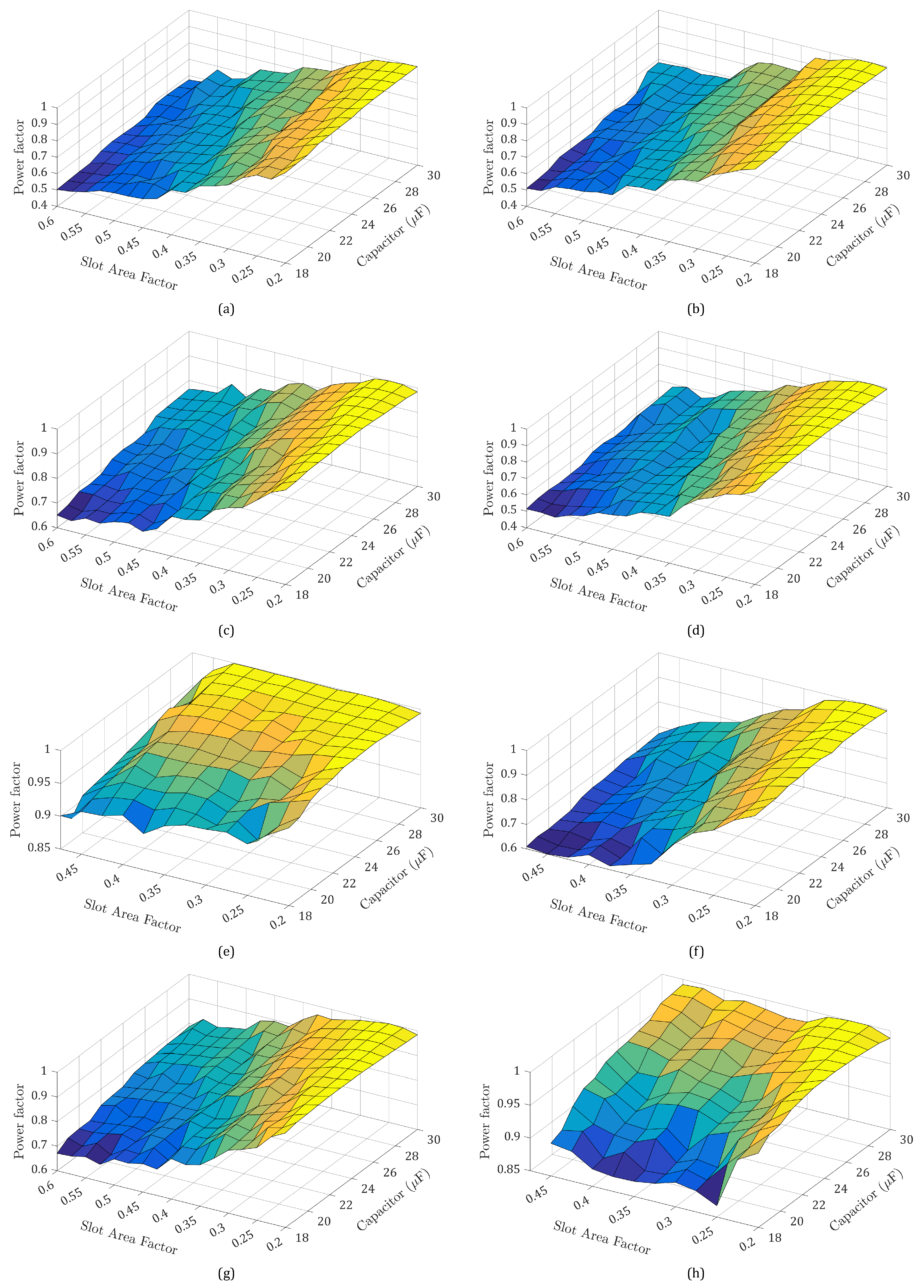
The design parameters and the performance quantities of the capacitor-run SPIMs with the highest efficiency (i.e., with k b a r = 0.2) are summarized in Table 3, Table 4, Table 5, Table 6, Table 7, Table 8, Table 9 and Table 10. The half-view (½) part of these machines as well as the magnetic flux density distribution under the motor’s nominal operation are shown in Figure 7. For the specific SPIMs, the subsequent comments can be made:
(a)
The constraints regarding: (i) the motor’s net mass (i.e., M 14.0 kg), (ii) the main/ auxiliary winding current densities (i.e., J m , J a ≤3.5 A/mm 2 ), and (iii) the starting to nominal torque ratio (i.e., T s t / T n 0.35) are met. Moreover, the starting to nominal current ratio ( I s t / I n ) is always lower than 8.0. The SPIMs with pent and rectangular rotor bars present the lowest values for this ratio, and they have clear advantage over the other models. The I s t / I n ratio ranges from 4.61 to 6.24 for the machines with bars of pentagonal shape. The ratio value ranges from 4.82 to 6.42 when rectangular bars are utilized. On the contrary, the topologies with trapezoidal bars exhibit the highest values for this ratio, i.e., 6.52–7.17. The starting current decreases notably as the rotor bar’s cross-sectional area becomes smaller and a capacitance of high value is used.
(b)
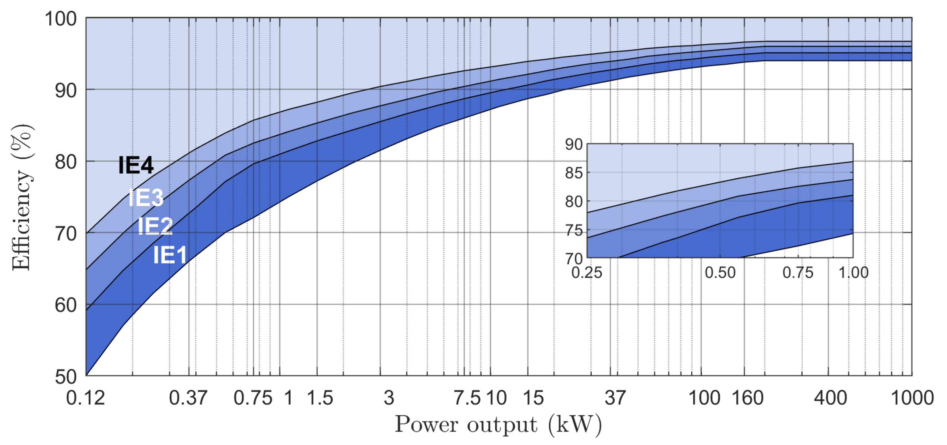
The efficiency of the SPIM with quadrangular bars and C r u n = 25 μ F is equal to 84.33%, and it is the maximum one among the highest recorded values. The minimum one (i.e., 83.91%) corresponds to the SPIM with C r u n = 26 μ F and bars of pent shape. The difference between the above efficiency values is equal to 0.42%. It comes as a result of the fact that the specific motor with quadrangular bars present lower stator windings copper losses and rotor ohmic losses. For given C r u n , the efficiency of the SPIMs with different rotor bar geometry exhibits considerable variation. The difference between the minimum and maximum efficiency values is lower than 0.5% when C r u n 26 μ F. The respective difference lies between 0.55% and 0.98% as the C r u n varies from 18 μ F to 25 μ F. This is due to the variation of: (i) the stator windings copper losses, (ii) the rotor ohmic losses, and (iii) the iron losses. Further information about the effect of the rotor bar’s shape on the rotor ohmic losses is given in Section 8. Generally-speaking, the efficiency ranges from 82.82% to 84.33%. The maximum value of the analyzed SPIMs is quite close to that of IE4 efficiency class (i.e., 85.7%).
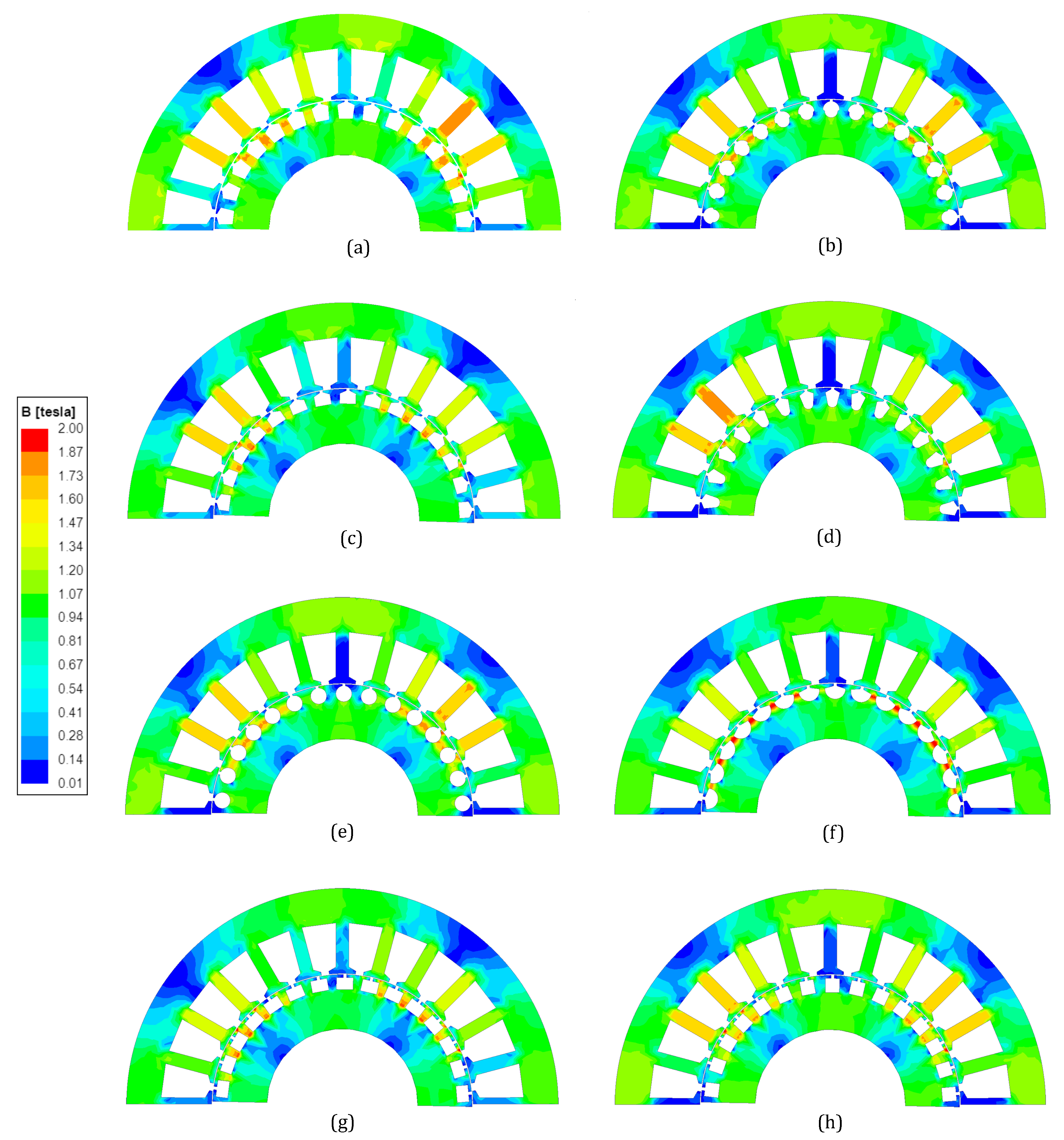
(c)
The motors with bars of rectangular and pent shape have the lowest stator and rotor core losses.
(d)
No severe magnetic saturation is observed at the SPIM’s stator and rotor teeth. The only exceptions are the models with bars of drop shape, where the magnetic flux density at the rotor’s teeth is higher than 1.70 T.
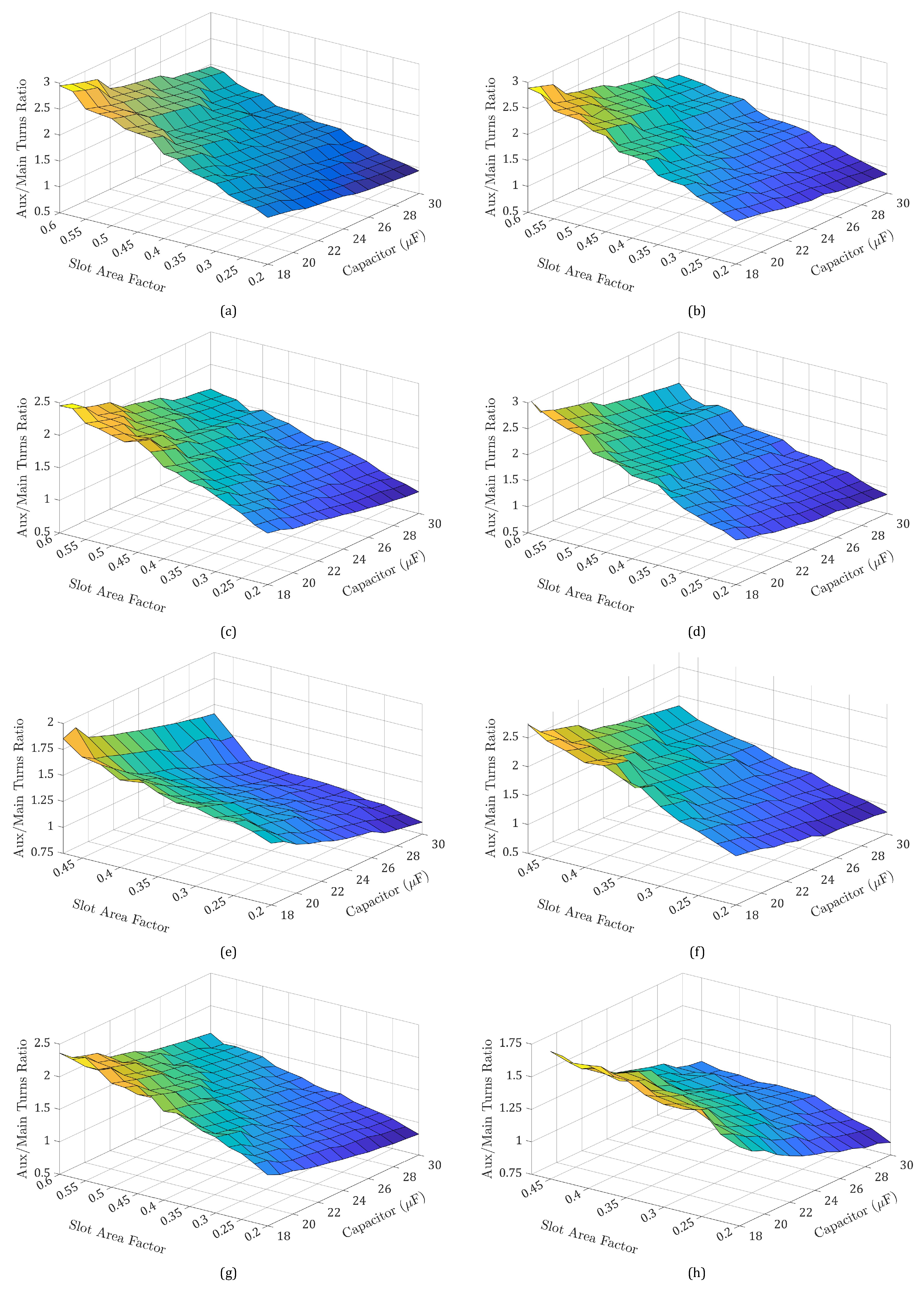
(e)
The angle between the currents of the main and auxiliary winding ( θ ) augments as a higher value is assigned to C r u n . Only a few exceptions exist at the final SPIMs. The shift angle is close enough or equal to the ideal value (i.e., 90 electrical degrees) for the whole variation range of C r u n . The achievement of the ideal angle value is crucial for two reasons. The first one refers to the generation of circular rotating fields. Unlike the three-phase IMs, circular rotating fields are not inherently formed at the capacitor-run SPIMs. Rotating fields with elliptical shape are produced due to the backward fields, especially when the shift angle is far away from 90 electrical degrees. When the above happens, the motor’s performance is substantially degraded. The second reason is related to the maximization of the SPIM’s delivered output torque for given absorbed current. A high value of C r u n is preferable at the machines with pent and rectangular bars, aiming for the currents shift angle to approach the ideal value. The shift angle becomes higher than 90 electrical degrees when trapezoidal bars are incorporated and C r u n 23 μ F. With respect to the ideal angle, a lower value is preferable rather than a higher one. In the latter case, the SPIM’s operation may be noisy due to the torque fluctuations and the vibrations.
(f)
A necessary condition for the SPIM’s torque ripple minimization (besides the slotting and higher-order current harmonics effect reduction) is the ratio of the main to auxiliary winding current amplitudes ( I m / I a ) to be equal to the turns ratio. This condition is fulfilled, as the value of the I m / I a ratio is almost equal to the turns ratio.
(g)
The breakdown torque ( T m ) declines when a higher capacitance is employed. At the commercial capacitor-run SPIMs with the same output power ratings and specifications, the breakdown to nominal torque ratio ( T m / T n ) ratio is usually equal to 1.80. This requirement is satisfied at the obtained SPIMs. The minimum (when C r u n = 30 μ F) and the maximum (when C r u n = 18 μ F) values of the T m / T n ratio are tabulated in Table 11. From the data given there, it is concluded that the SPIMs with trapezoidal bars are advantageous. For all the machines, it was found that the breakdown torque is proportional to the square of the main winding turns number. Furthermore, the T m is almost inversely proportional to the sum of: (i) the main winding resistance, (ii) the main winding leakage reactance, (iii) the rotor squirrel-cage resistance, and (iv) the rotor-squirrel-cage leakage reactance.

8. Further Considerations

This section provides insight into aspects concerning SPIM’s operational characteristics that have to be taken into account by the designer.

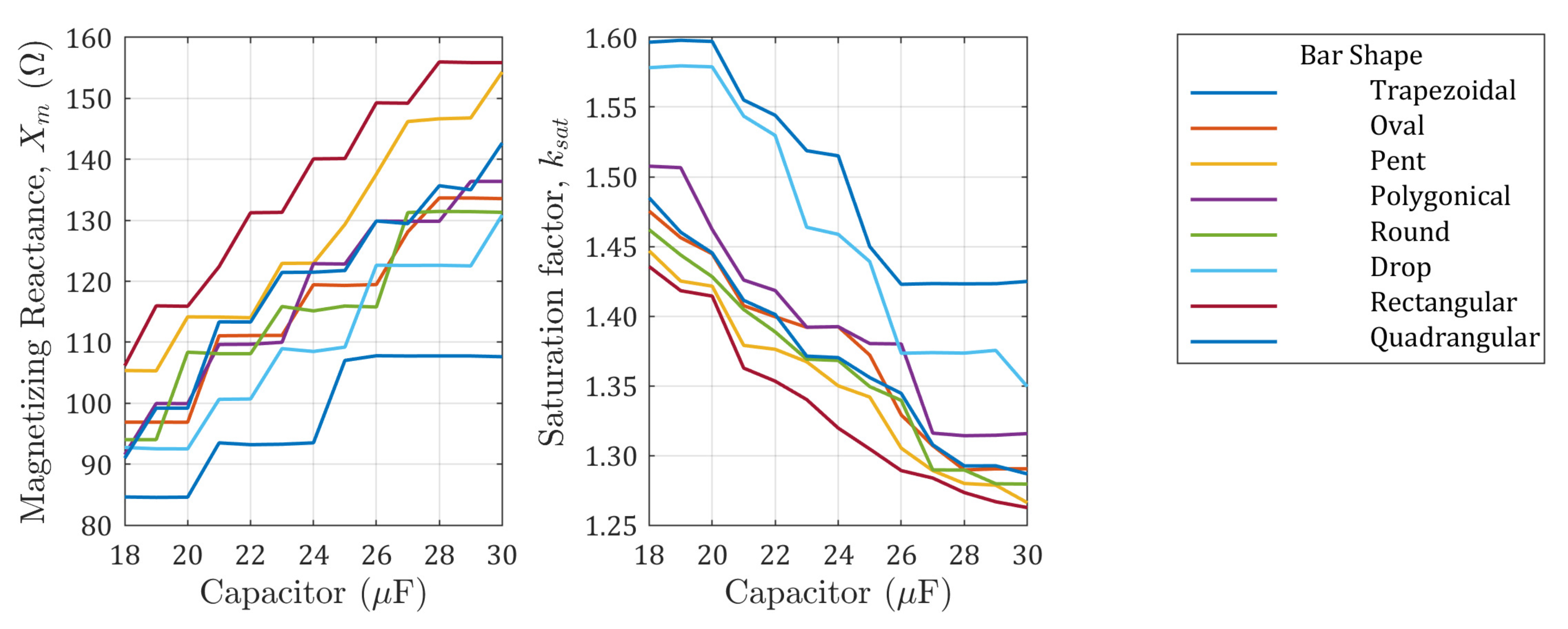
8.1. Effect of Capacitance on Magnetizing Reactance and Magnetic Saturation Factor

The magnetizing reactance ( X m ) variation as a function of the run-capacitor value ( C r u n ) for the SPIMs with k b a r = 0.2 is depicted in Figure 8. The X m increases as the C r u n becomes higher, since a larger number of main winding turns ( N m ) are utilized (Table 3, Table 4, Table 5, Table 6, Table 7, Table 8, Table 9 and Table 10). The specific quantity is strongly dependent on the N m . It is also affected by the rotor bar’s shape due to the resulted magnetic saturation. The above is apparent from the topologies with C r u n = 18 μ F, N m = 360, and trapezoidal, quadrangular, polygonical, and drop bars. Although the above motors have the same N m , their X m is different. The SPIM with trapezoidal bars has the lowest X m , while that with rotor slots of drop shape has the highest one. In general, the rotor squirrel-cage configurations with rectangular and pent bars conclude to the highest values for the X m .
The magnetic saturation factor ( k s a t ) variation as a function of C r u n for the machines with k b a r = 0.2 is also given in Figure 8. The k s a t represents the ratio of the total magnetomotive force to the airgap magnetomotive force. Its value declines as the C r u n augments. This coincides with the tendency of the SPIM’s iron losses, which become lower for a higher capacitance, as already mentioned in Section 6. Based on the k s a t values, it can be said that the magnetic saturation level is moderate. The highest k s a t is recorded for the SPIMs with trapezoidal and drop rotor bars.

8.2. Impact of Skin Effect on the Rotor Bars Resistance and Leakage Reactance

As noted in Section 5, the skin effect is a phenomenon that takes place at the squirrel-cage rotor bars. In order to demonstrate its influence on the rotor ohmic losses, the variation of the bars’ resistance coefficient ( K r ) and leakage reactance coefficient ( K x ) as a function of the motor’s slip is illustrated in Figure 9 for five indicative k b a r values. The results refer to the SPIMs with C r u n = 18 μ F and rectangular bars. The coefficients K r and K x establish the ratio between the AC and DC resistance as well as the reactance, respectively. From Figure 9, it can be seen that the K r tends to 1.0 for low slip values, independently of the k b a r value. This means that the impact of the skin effect can be neglected in this case. As the slip increases, the K r augments. The influence of this phenomenon is more intense when the rotor bar’s cross-sectional area is becoming larger. The K x follows a different trend. It is almost equal to 1.0 when the slip is close to zero and decreases with the slip increment. Once again, the impact of the skin effect is more prominent for high values of k b a r . The variation of K r and K x for k b a r = 0.2 indicates that the AC rotor ohmic losses are quite close to the DC ones. Thus, it seems that the skin effect is less important at the low-power SPIMs.

8.3. Effect of Bar’s Shape on the Rotor Ohmic Losses

The rotor bar’s shape affects greatly the rotor ohmic losses, as it can be concluded from the data of Table 12 and Table 13, where the certain losses are summarized for the minimum and maximum k b a r values examined in each case. The losses increase as the C r u n rises to higher values and the bar’s cross-sectional area is becoming larger. For k b a r = 0.2, the SPIMs with bars of rectangular and pent shape have the lowest losses of this type. The rotor ohmic losses minimization does not always coincide with the efficiency maximization. This is clear by considering the machines with trapezoidal bars. Despite the fact that these motors exhibit the lowest rotor ohmic losses for the whole variation range of C r u n , their efficiency is lower in some cases than the corresponding one of the other SPIMs according to the data of Table 3, Table 4, Table 5, Table 6, Table 7, Table 8, Table 9 and Table 10. This proves that the rotor bar’s geometry has also a significant impact on the rest of the SPIM’s particular losses and especially on the iron losses and stator windings copper losses.

9. Conclusions

In this paper, the impact of the rotor bar’s geometry on the capacitor-run SPIM’s efficiency was analyzed and presented. The findings indicate that the bar’s shape influences considerably the specific performance quantity. The difference between the minimum and maximum efficiency values of the SPIMs with the highest performance is equal to 0.42%. For given capacitance, the difference between the minimum and the maximum efficiency values of the SPIMs with different rotor bar geometry ranges from 0.31% up to 0.98%. In spite of the above, it was highlighted that the bar design has a notable effect on other SPIM’s operational characteristics, such as the motor’s particular losses, starting current, breakdown torque, currents shift angle, magnetic saturation, etc. Thus, useful conclusions were drawn through the analytical comparison of the derived SPIMs and the discussion of the results. The efficiency of these machines was found to be higher than that of the IE3 (premium) efficiency class and quite close to that of the IE4 (super premium) efficiency class. So, this work provides an insight into the development of capacitor-run SPIMs with enhanced efficiency, while it simultaneously deals with aspects such as the impact of skin effect on the rotor ohmic losses and the influence of capacitance on the motor’s magnetizing inductance. The efficiency target fulfillment is independent of the rotor bar’s shape and comes as a result of the bar’s cross-sectional determination in conjunction with the proper selection of the run-capacitor value and auxiliary to main winding turns ratio. Thus, the proposed design methodology offers to designers and manufacturers great flexibility in the rotor squirrel-cage design. In addition, the generalization of this design approach is validated, and its applicability is expanded.

Author Contributions

Conceptualization, I.D.C. and Y.L.K.; methodology, I.D.C. and F.S.; software, I.D.C. and Y.L.K.; validation, I.D.C., Y.L.K. and F.S.; formal analysis, I.D.C. and F.S.; investigation, I.D.C.; writing—original draft preparation, I.D.C.; writing—review and editing, Y.L.K. and F.S.; visualization, Y.L.K.; supervision, Y.L.K.; All authors have read and agreed to the published version of the manuscript.

Funding

This research received no external funding.

Institutional Review Board Statement

Not applicable.

Informed Consent Statement

Not applicable.

Conflicts of Interest

The authors declare no conflict of interest.

References

  1. Wang, X.; Zhong, H.; Yang, Y.; Mu, X. Study of a Novel Energy Efficient Single-Phase Induction Motor with Three Series-Connected Windings and Two Capacitors. IEEE Trans. Energy Convers. 2010, 25, 433–440. [Google Scholar] [CrossRef]
  2. Chasiotis, I.D.; Karnavas, Y.L. On the Design and Manufacturing of Small Single Phase Induction Motors toward Super Premium Efficiency Standards. In Proceedings of the 2020 International Conference on Electrical Machines (ICEM), Göthenburg, Sweden, 23–26 August 2020; pp. 2321–2327. [Google Scholar] [CrossRef]
  3. Lee, K.S.; Lee, S.H.; Park, J.H.; Kim, J.M.; Choi, J.Y. Experimental and Analytical Study of Single-Phase Squirrel-Cage Induction Motor Considering End-Ring Porosity Rate. IEEE Trans. Magn. 2017, 53, 1–4. [Google Scholar] [CrossRef]
  4. Yun, J.; Lee, S.B. Influence of Aluminum Die-Cast Rotor Porosity on the Efficiency of Induction Machines. IEEE Trans. Magn. 2018, 54, 1–5. [Google Scholar] [CrossRef]
  5. Chasiotis, I.D.; Karnavas, Y.L. Investigation on Single Phase Induction Motor Efficiency and Starting Capability Enhancement by Incorporating Magnesium Alloys Rotors. Int. J. Sci. Res. Mach. Technol. Mater. 2020, 14, 16–19. [Google Scholar]
  6. Liang, D.; Zhou, V. Recent Market and Technical Trends in Copper Rotors for High-Efficiency Induction Motors. In Proceedings of the International Power Electronics Conference (IPEC-Niigata 2018—ECCE Asia), Niigara, Japan, 20–24 May 2018; pp. 1943–1948. [Google Scholar] [CrossRef]
  7. Ferreira, F.J.T.E.; Baoming, G.; de Almeida, A.T. Reliability and Operation of High-Efficiency Induction Motors. IEEE Trans. Ind. Appl. 2016, 52, 4628–4637. [Google Scholar] [CrossRef]
  8. Sarac, V.; Atanasova-Pacemska, T. Multiparameter Analysis for Efficiency Improvement of Single-Phase Capacitor Motor. Math. Probl. Eng. 2019, 2019, 5131696. [Google Scholar] [CrossRef] [Green Version]
  9. De Almeida, A.T.; Ferreira, F.J.T.E.; Duarte, A.Q. Technical and Economical Considerations on Super High-Efficiency Three-Phase Motors. IEEE Trans. Ind. Appl. 2014, 50, 1274–1285. [Google Scholar] [CrossRef]
  10. Office of Energy Efficiency & Renewable Energy. Energy Conservation Program: Energy Conservation Standards for Small Electric Motors; Final Rule; Technical Report 86 FR 4885; U.S. Department of Energy: Washington, DC, USA, 2010.
  11. de Almeida, A.T.; Ferreira, F.J.T.E.; Baoming, G. Beyond Induction Motors?Technology Trends to Move Up Efficiency. IEEE Trans. Ind. Appl. 2014, 50, 2103–2114. [Google Scholar] [CrossRef]
  12. CLC/TC 2 Rotating machinery Technical Committee. Rotating Electrical Machines—Part 30-1: Efficiency Classes of Line Operated AC Motors (IE Code); Technical Report EN 60034-30-1; International Electrotechnical Commission (IEC): Geneva, Switzerland, 2014. [Google Scholar]
  13. Pillay, P.; Al-Badri, M.; Angers, P.; Desai, C. A New Stray-Load Loss Formula for Small and Medium-Sized Induction Motors. IEEE Trans. Energy Convers. 2016, 31, 1221–1227. [Google Scholar] [CrossRef]
  14. Bacher, J.; Waldhart, F.; Muetze, A. 3-D FEM Calculation of Electromagnetic Properties of Single-Phase Induction Machines. IEEE Trans. Energy Convers. 2015, 30, 142–149. [Google Scholar] [CrossRef]
  15. Kurt, M.S.; Fenercioglu, A. Rotor Slot Distance Effects on Output Parameters in Single Phase Induction Motors. Hittite J. Sci. Eng. 2018, 5, 31–35. [Google Scholar] [CrossRef] [Green Version]
  16. Lee, H.J.; Im, S.H.; Um, D.Y.; Park, G.S. A Design of Rotor Bar for Improving Starting Torque by Analyzing Rotor Resistance and Reactance in Squirrel Cage Induction Motor. IEEE Trans. Magn. 2018, 54, 1–4. [Google Scholar] [CrossRef]
  17. Yousefian, M.; Mosaddegh, H.R.; Zarchi, H.A. Optimal Design of a Single-Phase Two-Value Capacitor Induction Motor with Fan Load. In Proceedings of the Iranian Conference on Electrical Engineering (ICEE), Mashhad, Iran, 8–10 May 2018; pp. 1298–1303. [Google Scholar] [CrossRef]
  18. Mach, M.; Cipin, R.; Toman, M.; Hajek, V. Impact of Number of Rotor Slots on Performance of Three-Phase and Single-Phase Induction Machines. In Proceedings of the 2018 IEEE International Conference on Environment and Electrical Engineering and 2018 IEEE Industrial and Commercial Power Systems Europe (EEEIC/I CPS Europe), Palermo, Italy, 12–15 June 2018; pp. 1–6. [Google Scholar] [CrossRef]
  19. Heo, C.G.; Kim, H.M.; Park, G.S. A Design of Rotor Bar Inclination in Squirrel Cage Induction Motor. IEEE Trans. Magn. 2017, 53, 1–4. [Google Scholar] [CrossRef]
  20. Hosseini, S.M. Performance improvement of capacitor-run single-phase induction motors by non-orthogonal armature windings. In Proceedings of the International Symposium on Power Electronics, Electrical Drives, Automation and Motion (SPEEDAM), Anacapri, Italy, 22–24 June 2016; pp. 1336–1341. [Google Scholar] [CrossRef]
  21. Elkholy, M.M. Optimal Energy Saving for Variable Speed Single Phase Induction Motor Drives. In Proceedings of the 19th International Middle East Power Systems Conference (MEPCON), Cairo, Egypt, 19–21 December 2017; pp. 753–764. [Google Scholar] [CrossRef]
  22. Abdel-Khalik, A.S.; Diab, M.S.; Ahmed, S.; Massoud, A.M. A New Single Tooth Winding Layout for a Single-Phase Induction Motor with Segmented Stator. In Proceedings of the 41st Annual Conference of the IEEE Industrial Electronics Society IECON, Yokohama, Japan, 9–12 November 2015; pp. 102–107. [Google Scholar] [CrossRef]
  23. Mallard, V.; Parent, G.; Demian, C.; Brudny, J.F.; Delamotte, A. Increasing the Energy Efficiency of Induction Machines by the Use of Grain-Oriented Magnetic Materials and Die Casting Copper Squirrel Cage in the Rotor. IEEE Trans. Ind. Appl. 2019, 55, 1280–1289. [Google Scholar] [CrossRef]
  24. Liu, Y.; Han, P.; Bazzi, A.M. A Comparison of Rotor Bar Material of Squirrel-Cage Induction Machines for Efficiency Enhancement Purposes. In Proceedings of the 17th European Conference on Power Electronics and Applications (EPE’15 ECCE-Europe), Geneva, Switzerland, 8–10 September 2015; pp. 1–7. [Google Scholar] [CrossRef]
  25. Szab?, L. A Survey on the Efficiency Improve of Electrical Machines. In Proceedings of the 26th International Workshop on Electric Drives: Improvement in Efficiency of Electric Drives (IWED), Moscow, Russia, 30 January–2 February 2019; pp. 1–6. [Google Scholar] [CrossRef]
  26. Cavagnino, A.; Vaschetto, S.; Ferraris, L.; Gmyrek, Z.; Agamloh, E.B.; Bramerdorfer, G. Striving for the Highest Efficiency Class With Minimal Impact for Induction Motor Manufacturers. IEEE Trans. Ind. Appl. 2020, 56, 194–204. [Google Scholar] [CrossRef]
  27. Um, D.Y.; Park, G.S. Determination Scheme of Stator Parameters for Making Rotating Fields Circular in a Single-Phase Induction Motor. IEEE Trans. Magn. 2020, 56, 1–5. [Google Scholar] [CrossRef]
  28. Chasiotis, I.D.; Karnavas, Y.L. A Novel Design Methodology for the Compliance of Single Phase Induction Motors with Recent Industrial Premium Efficiency Standards. Eng. Rep. 2020, 2, e12265. [Google Scholar] [CrossRef]
  29. Karnavas, Y.L.; Chasiotis, I.D. Design and Manufacturing of a Single-Phase Induction Motor: A Decision Aid Tool Approach. Int. Trans. Electr. Energy Syst. 2017, 27, e2357. [Google Scholar] [CrossRef]
  30. Boldea, I.; Nasar, S.A. The Induction Machines Design Handbook, 2nd ed.; CRC Press: Boca Raton, FL, USA, 2010. [Google Scholar]
  31. Zhao, H.; Guo, X.; Eldeeb, H.H.; Xu, G.; Zhan, Y.; Mohammed, O.A. Design and Analysis of Inverter-Fed High-Speed Induction Motors with Closed Rotor Slots Taking Enclosure Effect into Account. In Proceedings of the IEEE Applied Power Electronics Conference and Exposition (APEC), New Orleans, LA, USA, 15–19 March 2020; pp. 729–733. [Google Scholar] [CrossRef]
  32. Donolo, P.; Bossio, G.; De Angelo, C. Analysis of Voltage Unbalance Effects on Induction Motors with Open and Closed Slots. Energy Convers. Manag. 2011, 52, 2024–2030. [Google Scholar] [CrossRef]
  33. Yang, W.; Huang, C.; Zhang, Q. Optimization of Squirrel-Cage Rotor for Amorphous Asynchronous Motor. In Proceedings of the 2019 Chinese Automation Congress (CAC), Hangzhou, China, 22–24 November 2019; pp. 2107–2110. [Google Scholar] [CrossRef]
  34. Makhetha, E.; Muteba, M.; Nicolae, D.V. Effect of Rotor bar Shape and Stator Slot Opening on the Performance of Three Phase Squirrel Cage Induction Motors with Broken Rotor Bars. In Proceedings of the Southern African Universities Power Engineering Conference/Robotics and Mechatronics/Pattern Recognition Association of South Africa (SAUPEC/RobMech/PRASA), Bloemfontein, South Africa, 28–30 January 2019; pp. 463–468. [Google Scholar] [CrossRef]
  35. Maloma, E.; Muteba, M.; Nicolae, D.V. Effect of Rotor Bar Shape on the Performance of Three Phase Induction Motors with Broken Rotor Bars. In Proceedings of the International Conference on Optimization of Electrical and Electronic Equipment (OPTIM) & 2017 Intl Aegean Conference on Electrical Machines and Power Electronics (ACEMP), Brasov, Romania, 25–27 May 2017; pp. 364–369. [Google Scholar] [CrossRef]
  36. Nardo, M.D.; Marfoli, A.; Degano, M.; Gerada, C.; Chen, W. Rotor Design Optimization of Squirrel Cage Induction Motor—Part II: Results Discussion. IEEE Trans. Energy Convers. 2021, 36, 1280–1288. [Google Scholar] [CrossRef]
  37. Lee, G.; Min, S.; Hong, J.P. Optimal Shape Design of Rotor Slot in Squirrel-Cage Induction Motor Considering Torque Characteristics. IEEE Trans. Magn. 2013, 49, 2197–2200. [Google Scholar] [CrossRef]
  38. Marfoli, A.; Nardo, M.D.; Degano, M.; Gerada, C.; Chen, W. Rotor Design Optimization of Squirrel Cage Induction Motor—Part I: Problem Statement. IEEE Trans. Energy Convers. 2021, 36, 1271–1279. [Google Scholar] [CrossRef]
  39. Sorgdrager, A.J.; Wang, R.J.; Grobler, A.J. Transient Performance Investigation and Taguchi Optimization of a Line-Start PMSM. In Proceedings of the 2015 IEEE International Electric Machines Drives Conference (IEMDC), Coeur d’ Alene, ID, USA, 10–13 May 2015; pp. 590–595. [Google Scholar] [CrossRef]
  40. Sorgdrager, A.J.; Wang, R.J.; Grobler, A.J. Multiobjective Design of a Line-Start PM Motor Using the Taguchi Method. IEEE Trans. Ind. Appl. 2018, 54, 4167–4176. [Google Scholar] [CrossRef]
  41. Lyskawinski, W.; Jedryczka, C.; Szelag, W. Influence of Magnet and Cage Shape on Properties of the Line Start Synchronous Motor with Powder Hybrid Rotor. In Proceedings of the International Symposium on Electrical Machines (SME), Naleczow, Poland, 18–21 June 2017; pp. 1–6. [Google Scholar] [CrossRef]
  42. Lu, W.; Luo, Y.; Zhao, H. Influences of Rotor Bar Design on the Starting Performance of Line-Start Permanent Magnet Synchronous Motor. In Proceedings of the 6th International Conference on Electromagnetic Field Problems and Applications (ICEF), Dalian, China, 19–21 June 2012; pp. 1–4. [Google Scholar] [CrossRef]
  43. Kersten, A.; Liu, Y.; Pehrman, D.; Thiringer, T. Rotor Design of Line-Start Synchronous Reluctance Machine with Round Bars. IEEE Trans. Ind. Appl. 2019, 55, 3685–3696. [Google Scholar] [CrossRef]
Figure 1. International efficiency classes for four-pole IMs at 50 Hz [12].
Energies 15 00717 g001
Figure 2. (a) Representation of the used stator topology and (b) 3D view of the SPIM topology under study.
Energies 15 00717 g002
Figure 3. The cross-section variation as a function of k b a r for the rotor bar with (a) trapezoidal, (b) oval, (c) pent, (d) polygonical, (e) round, (f) drop, (g) rectangular, and (h) quadrangular shape.
Energies 15 00717 g003
Figure 4. Impact of C r u n and k b a r on efficiency of SPIMs with rotor squirrel-cage bars of: (a) trapezoidal, (b) oval, (c) pent, (d) polygonical, (e) round, (f) drop, (g) rectangular, and (h) quadrangular shape.
Energies 15 00717 g004
Figure 5. Impact of C r u n and k b a r on power factor of SPIMs with rotor squirrel-cage bars of: (a) trapezoidal, (b) oval, (c) pent, (d) polygonical, (e) round, (f) drop, (g) rectangular, and (h) quadrangular shape.
Energies 15 00717 g005
Figure 6. Impact of C r u n and k b a r on auxiliary to main winding turns ratio of SPIMs with rotor squirrel-cage bars of: (a) trapezoidal, (b) oval, (c) pent, (d) polygonical, (e) round, (f) drop, (g) rectangular, and (h) quadrangular shape.
Energies 15 00717 g006
Figure 7. View (½) part and magnetic flux density distribution under nominal operation of the SPIM with C r u n = 18 μ F and rotor bars of: (a) trapezoidal, (b) oval, (c) pent, (d) polygonical, (e) round, (f) drop, (g) rectangular, and (h) quadrangular shape.
Energies 15 00717 g007
Figure 8. Variation of the SPIM’s magnetizing reactance (left) and magnetic saturation factor (right) as a function of the run-capacitor value for all the examined rotor bar shapes.
Energies 15 00717 g008
Figure 9. Variation of rotor bars resistance coefficient (left) and leakage reactance coefficient (right) as a function of the SPIM’s slip for different k b a r values.
Energies 15 00717 g009
Table 1. SPIM’s operational characteristics and applied constraints.
ParameterValue/Type
Rated output power, P n 746 W
Rated output torque, T n ≥4.8 Nm
Rated speed, n m ≥1400 rpm
Number of poles, 2 p 4
Supply voltage, U n 230 V
Supply frequency, f50 Hz
Line current at nominal operation, I n ≤5.0 A
Efficiency at nominal operation, η ≥82.5%
Power factor at nominal operation, c o s ϕ ≥0.9
Starting to nominal torque ratio, T s t / T n ≥0.35
Starting to nominal current ratio, I s t / I n ≤8.0
Main/aux. winding wire current density, J m / J a ≤3.50 A/mm 2
Net mass, M≤14.0 kg
MountingFoot
Insulation classB
Design typeN
Table 2. Minimum 50 Hz efficiency values defined in IEC/EN 60034-30-1:2014 for a four-pole/1.0 HP IM.
Efficiency Class Value (Minimum)
Standard EfficiencyIE172.1%
High EfficiencyIE279.6%
Premium EfficiencyIE382.5%
Super Premium EfficiencyIE485.7%
Table 3. Design parameters and performance quantities of the SPIMs with rotor bars of trapezoidal shape.
C run ( μ F) η % cos ϕ a N a N m I st (A) I st / I n M (kg) θ (deg) I m / I a
1883.020.9511.40050436029.467.1712.1488.631.460
1982.940.9561.35648836029.437.1812.0890.111.401
2082.820.9581.31147236029.397.1812.0392.021.368
2183.310.9781.23945636827.917.0111.9490.431.269
2283.530.9801.19644036827.877.0311.8092.501.232
2383.430.9831.17443236827.847.0411.8693.881.184
2483.350.9851.13041636827.807.0311.8295.411.161
2583.680.9951.04240038426.186.7311.7893.941.094
2684.090.9991.02139238425.426.5811.7493.861.035
2784.010.9991.00038438425.396.5611.7295.061.002
2883.931.0000.95836838425.356.5511.6896.490.981
2983.841.0000.93836038425.316.5411.6597.750.957
3083.761.0000.93836038425.286.5211.6498.620.917
Table 4. Design parameters and performance quantities of the SPIMs with rotor bars of oval shape.
C run ( μ F) η % cos ϕ a N a N m I st (A) I st / I n M (kg) θ (deg) I m / I a
1883.530.9721.32648836827.256.8212.0584.511.42
1983.450.9751.28347236826.916.7512.0086.411.38
2083.370.9771.23945636826.846.7411.9488.081.33
2183.510.9901.16744838425.336.4611.9286.391.23
2283.990.9951.12543238424.826.3911.8586.801.18
2383.920.9961.08341638424.586.3411.8188.571.15
2483.940.9991.04140839224.316.2911.7787.801.09
2583.710.9981.02040039223.446.0511.7590.921.05
2684.180.9990.98038439223.356.0411.7090.661.03
2783.990.9980.94037640021.635.5911.5489.080.99
2883.970.9950.90236840820.915.3911.5288.650.94
2983.900.9940.88236040820.875.3611.5089.900.92
3084.110.9920.86335240820.835.3611.4791.570.89
Table 5. Design parameters and performance quantities of the SPIMs with rotor bars of pent shape.
C run ( μ F) η % cos ϕ a N a N m I st (A) I st / I n M (kg) θ (deg) I m / I a
1883.630.9831.29249638424.626.2412.0781.351.39
1983.560.9861.25048038424.596.2512.0282.971.33
2083.720.9931.18446439223.446.0111.9482.091.27
2183.650.9951.14344839223.406.0111.9083.731.23
2283.740.9961.12244039223.376.0111.8886.101.18
2383.691.0001.06042440021.635.5811.6983.911.12
2483.621.0001.04041640021.595.5611.6585.731.09
2583.880.9990.98040040820.775.3711.6186.261.06
2683.910.9970.94239241619.885.1311.5984.880.99
2783.870.9930.90638442419.034.8911.5784.170.96
2883.840.9910.86836842418.994.8611.5385.350.94
2983.750.9910.84936042418.954.8511.5087.350.93
3083.670.9830.83336043218.154.6111.4985.880.87
Table 6. Design parameters and performance quantities of the SPIMs with rotor bars of polygonical shape.
C run ( μ F) η % cos ϕ a N a N m I st (A) I st / I n M (kg) θ (deg) I m / I a
1883.170.9641.35648836027.386.7712.0586.221.44
1983.480.9801.28347236826.046.5711.9884.781.34
2083.400.9831.23945636826.006.5711.9386.481.29
2183.930.9931.14644038424.536.2911.8885.581.23
2283.850.9941.10442438424.496.2911.8387.501.20
2383.790.9971.08341638423.826.1411.8087.751.14
2484.011.0001.02040039223.706.1211.7486.591.10
2584.221.0001.00039239222.705.8811.7188.051.05
2683.851.0001.00038438422.665.8711.6992.451.04
2783.810.9980.94037640020.995.4111.5388.480.98
2883.740.9970.92036840020.955.4011.4989.950.96
2983.790.9920.88236040820.245.1911.4988.970.90
3084.000.9910.86335240820.205.1811.4690.650.88
Table 7. Design parameters and performance quantities of the SPIMs with rotor bars of round shape.
C run ( μ F) η % cos ϕ a N a N m I st (A) I st / I n M (kg) θ (deg) I m / I a
1883.380.9681.34849636827.006.7412.0885.291.43
1983.300.9721.30448036826.966.7212.0586.921.37
2083.580.9861.22947238425.436.4611.9685.431.29
2183.960.9921.16744838424.726.3411.9185.761.22
2283.880.9941.12543238424.696.3311.8787.431.19
2383.970.9991.08242439223.546.0811.8386.311.12
2483.840.9991.06141639223.506.0711.7988.431.10
2583.770.9991.02040039223.466.0511.7589.701.06
2684.031.0001.00039239223.426.0711.7391.091.01
2783.950.9980.94138440820.985.4211.5688.150.98
2883.880.9970.90236840820.945.4011.5389.590.95
2983.810.9950.88236040820.915.3811.5090.820.93
3084.010.9940.86335240820.865.3811.4892.480.91
Table 8. Design parameters and performance quantities of the SPIMs with rotor bars of drop shape.
C run ( μ F) η % cos ϕ a N a N m I st (A) I st / I n M (kg) θ (deg) I m / I a
1883.370.9651.33348036028.066.9712.0686.121.44
1983.310.9701.31147236028.026.9712.0287.481.37
2083.210.9731.26745636027.696.9211.9689.291.33
2183.800.9861.19644036826.456.7411.8988.621.25
2283.580.9871.15242436826.416.7311.8590.671.21
2383.830.9961.08341638425.986.6811.8288.971.15
2483.780.9971.06240838424.926.4311.7990.041.09
2583.350.9881.04240038424.896.3211.7489.731.08
2684.251.0000.98038439223.055.9911.7189.471.01
2784.180.9990.95937639223.015.9711.6890.770.98
2884.110.9980.93936839222.975.9511.6492.160.96
2984.040.9970.91836039222.945.9311.6393.070.91
3084.110.9930.88035240021.265.4711.4791.990.88
Table 9. Design parameters and performance quantities of the SPIMs with rotor bars of rectangular shape.
C run ( μ F) η % cos ϕ a N a N m I st (A) I st / I n M (kg) θ (deg) I m / I a
1883.640.9841.28650439225.306.4212.1683.711.39
1983.770.9931.20048040023.335.9811.9483.041.34
2083.720.9951.16046440023.315.9811.9084.511.28
2183.750.9981.09844840822.525.8011.8584.801.25
2284.011.0001.05844041621.565.6011.8283.771.16
2384.041.0001.01942441621.525.5811.7785.601.14
2484.051.0000.98141642420.535.3111.7484.481.08
2583.980.9990.96240842420.495.3011.7186.251.06
2683.940.9950.90739243219.645.0611.6785.621.02
2784.160.9930.88938443219.605.0511.6587.060.98
2884.090.9890.85537644018.984.8611.6486.920.95
2984.060.9860.83636844018.954.8411.6287.760.91
3084.000.9830.81836044018.914.8211.5988.960.89
Table 10. Design parameters and performance quantities of the SPIMs with rotor bars of quadrangular shape.
C run ( μ F) η % cos ϕ a N a N m I st (A) I st / I n M (kg) θ (deg) I m / I a
1883.290.9631.35648836028.607.0712.0786.521.44
1983.600.9791.28347236827.066.8312.0085.201.34
2083.520.9821.23945636827.026.8311.9586.891.30
2184.020.9921.14644038425.516.5511.9086.231.24
2284.080.9961.10442438424.806.4011.8486.451.19
2384.201.0001.06141639223.676.1311.8185.011.12
2484.131.0001.04140839223.636.1211.7786.891.09
2584.331.0001.00039239223.596.1211.7388.581.06
2684.111.0000.96038440021.855.6611.5787.201.01
2784.050.9980.94037640021.825.6411.5488.360.97
2884.020.9950.90236840821.085.4411.5288.470.95
2983.930.9930.88236040821.055.4111.5189.370.91
3084.150.9880.84635241620.155.1611.4889.310.89
Table 11. Minimum and maximum T m / T n ratio values of the resulted SPIMs.
Rotor Bar Shapemin. T m / T n max. T m / T n
( C run = 30 μ F)( C run = 18 μ F)
Trapezoidal2.943.22
Oval2.472.99
Pent2.222.77
Polygonical2.423.05
Round2.473.01
Drop2.683.10
Rectangular2.272.83
Quadrangular2.403.14
Table 12. The SPIM’s rotor ohmic losses for the minimum and maximum k b a r values and indicative corresponding C r u n values, for rotor bars of trapezoidal, oval, pent and polygonical shape.
Bar Shape TrapezoidalOvalPentPolygonical
  k b a r 0.2 …0.60.2 …0.60.2 …0.60.2 …0.6
C r u n      
18 μ F 21.79 …6.7024.67 …6.8428.49 …11.4624.39 …6.30
20 μ F 21.83 …7.1124.56 …7.2229.82 …11.9825.64 …7.79
22 μ F 21.87 …8.1426.64 …8.2329.40 …12.6727.14 …8.83
24 μ F 21.93 …9.2727.89 …9.3231.16 …13.3327.81 …9.55
26 μ F 23.71 …10.0227.99 …9.6533.69 …14.5529.32 …10.65
28 μ F 23.83 …10.6830.48 …10.8435.35 …15.1130.80 …10.90
30 μ F 23.96 …11.8130.49 …10.6636.80 …16.3531.81 …12.36
Table 13. The SPIM’s rotor ohmic losses for the minimum and maximum k b a r values and indicative corresponding C r u n values, for rotor bars of round, drop, rectangular and quadrangular shape.
Bar Shape RoundDropRectangularQuadragular
  k b a r 0.2 …0.4750.2 …0.4750.2 …0.60.2 …0.45
C r u n      
18 μ F 24.72 …11.4923.23 …10.7928.19 …12.0923.19 …10.17
20 μ F 26.19 …13.6323.09 …12.0229.73 …12.6024.32 …10.78
22 μ F 26.87 …14.0024.19 …12.6132.12 …13.5426.57 …11.28
24 μ F 27.95 …15.5425.63 …14.2533.59 …13.9927.85 …11.92
26 μ F 28.70 …15.6127.75 …15.1035.14 …14.9629.29 …12.48
28 μ F 29.77 …17.7427.77 …16.5535.91 …15.5230.29 …13.35
30 μ F 30.64 …18.2829.27 …17.4636.19 …16.7331.79 …13.78
Publisher’s Note: MDPI stays neutral with regard to jurisdictional claims in published maps and institutional affiliations.

