
Cooling Effect of Water Channel with Vortex Generators on In-Wheel Driving Motors in Electric Vehicles


School of Mechanical Engineering, Yeungnam University, 280 Daehak-ro, Gyeongsan-si 712-749, Gyeongbuk-do, Korea
*
Author to whom correspondence should be addressed.
Energies 2022, 15(3), 722; https://0-doi-org.brum.beds.ac.uk/10.3390/en15030722
Submission received: 20 December 2021
/
Revised: 5 January 2022
/
Accepted: 6 January 2022
/
Published: 19 January 2022
(This article belongs to the Special Issue Numerical Simulation of Convective Heat Transfer)
Abstract
:Designing an effective cooling system for high-power-density in-wheel motors of electric vehicles is required to avoid the irreversible demagnetization of the permanent magnet due to a rise in its temperature. In this study, a water-cooling channel was used between the stator and housing to evaluate the cooling performance of a 25 kW in-wheel motor utilizing the commercially available software Ansys Fluent 19.2. Initially, cooling channels with a single or pair of vortex generators have been used with varying heights for pressure drop evaluation considering the allowable pressure drop of 0.7 bar for a water pump. The results indicates that both a single and a pair of vortex generators satisfy the limit of a pressure drop at the height of 4 and 3 mm, respectively, and the cooling performances of two vortex generators were evaluated at these heights. It has been found that the cooling performance of a permanent magnet is enhanced by 4.1% and 6.5% using a single and a pair of vortex generators, respectively, compared to the cooling channel without a vortex generator. Furthermore, considering the ram air effect on water-cooling channels of in-wheel motors under high-speed conditions, the temperature of the permanent magnet is decreased by about 2.1 °C and was found to be 148.8 °C under the temperature limit of demagnetization of the permanent magnet.
1. Introduction
In recent years, following the increase in worldwide awareness towards environmental issues such as climate change, stringent regulations have been established for greenhouse gas standards to achieve carbon neutrality. Accordingly, the development and commercialization of environmentally friendly electric vehicles have been accelerating, and the need for the research and development of core technologies for environmentally friendly power sources in electric vehicles has increased [1]. However, compared to the batteries used in internal combustion engines, the batteries used in electric vehicles are not sufficiently developed to produce large outputs; one of their limitations concerns battery thermal management for consistent performance [2,3]. Additionally, there is a decrease in mileage due to factors such as the weight of added parts. The in-wheel motor technology, which can reduce the vehicle weight, can be used to solve this problem. In an in-wheel motor, the suspension, steering, and braking components as well as the drive motor of the vehicle are built into the wheel; each motor is independently driven through distributed actuation [4]. In the case of the conventional inline motor method, significant power loss occurs when the power is delivered from the engine to the wheel. In contrast, the in-wheel motor method can reduce power loss with a minimized power delivery system and is advantageous for saving internal space. Furthermore, better steering performance compared to that of the inline motor method, which controls the drive shaft, can be achieved [4]. It is argued that the use of in-wheel motors increases the unsprung mass, leading to more discomfort of the passengers compared to the conventional powertrain system. Separate research is ongoing to eliminate the unsprung mass from the in-wheel motor for the sustainable development of in-wheel motors [5]. Considering the above facts, for the sustainable development of in-wheel motors, an effective thermal design is also necessary to regulate the temperature, which significantly affects the performance and durability of the in-wheel motor [6,7].
Cooling methods used for regulating the in-wheel motor temperature in electric vehicles are classified as air-cooling, oil-cooling, or water-cooling methods. In the air-cooling method, the heat generated by the motor is radiated through direct contact with external air. While driving, the heat generated from motor operation is dissipated through the heat exchange between the external housing surface encompassing the in-wheel motor and the surrounding air. A cooling groove on the housing surface, which is used for maximizing the heat exchange with the ram air, is crucial for these cooling methods, in which the air acts as a heat transfer medium [8]. The air-cooling method, which is the simplest among the three cooling methods, is adopted when the motor power is small or when there are difficulties in connecting the coolant pipes. However, the air-cooling method has limitations in controlling the amount of generated heat, which rapidly increases when the in-wheel motor rotates at a high speed as the vehicle drives. The oil-cooling method utilizes the pump with the oil as a cooling medium to circulate the oil inside and outside of the motor and reduce the heat. Oil has a higher convection coefficient than air. Therefore, the oil-cooling method demonstrates a higher thermal performance than the air-cooling method. It also enables direct spraying on the exothermic component [9]. Concurrently, cooling oil can be used for lubrication, which allows for an integrated module design with a reduction gear and increases the lifespan of the motor. However, the viscosity of the cooling oil may significantly vary according to the temperature at which a coolant is used to reduce the heat generated by the motor. The water-cooling method can use coolants with a higher convective heat transfer coefficient. Compared to other cooling methods, the water-cooling method exhibits a superior performance. When a coolant is used for the heat dissipation of the motor, the temperature of the permanent magnet and the winding temperature decrease by approximately 26% and 32%, respectively, compared to the case when a coolant is not used [10].
Various experimental and numerical studies have been carried out using water-cooling channels utilizing different configurations of the heat exchanger. Fasquelle and Laloy [11] used a water-cooling system applied in a permanent magnet synchronous motor and obtained the desired cooling performance of the synchronous motor. Another three-dimensional numerical study by Rehman and Seong utilized the cooling water jacket for the housing for a three-phase induction motor [12]. A higher cooling performance was reported for a six-pass cooling jacket with two-port configuration at a flow rate of 10 LPM for the safe operation at the maximum motor output. The oil-cooling channel with three cooling positions was studied for a traction motor of a hybrid electric vehicle in a numerical investigation by Huang et al. [13]. The authors reported that direct cooling methods were found to depict the smaller temperature rise of the stator. A water loop placed at the bottom of the teeth with two parallel flow paths by Li et al. [14], unlike the conventional water cooling in their experimental investigation, was found to be a promising method of end-winding cooling for an electric motor. In a numerical analysis, different shapes of cooling ducts such as spiral, U-shaped (one duct), U-shaped (bifurcated), and an axial water jacket were used between the housing and stator to investigate the cooling performance of the induction machine by Satrustegui et al. [15]. The authors reported a higher pressure drop for the axial water jacket than the spiral water jacket for the same heat transfer. Studies have also been carried out using water–ethylene glycol in the spiral cooling channel of an electric motor by Deriszadeh et al. [16]. The authors reported that the cooling performance of the motor increased with the increase in ethylene glycol concentration and number of turns for the spiral channel, and the heat transfer coefficient subsequently increased. Furthermore, the increase in the heat transfer coefficient was more significant than the increase in the pressure drop. Yang et al. [17] tested and simulated oil jacket cooling for an electric motor. It was suggested that the cooling performance of the motor was better at a smaller height and width of the channel but at the cost of a higher pressure drop.
It is evident from the above literature that numerous designs of the cooling channel have been used at different locations of the electric motor. However, more designs need to be identified that deliver a higher cooling performance for an electric motor. In addition, there have been no studies utilizing the different turbulence enhancers (vortex generator) for a water-cooling channel. A higher cooling performance is expected when the coolant proceeds in a turbulent flow by joining the different passages of the water channel with multiple corners, compared to the case when the coolant proceeds via a plain water channel in a laminar flow [18]. Moreover, to avoid problems associated with insulation or corrosion, direct contact between the motor components and the coolant should be prevented. Therefore, a separate water-cooling channel is thus necessary. In addition, water mixed with ethylene glycol lowers the freezing point of water. The heating of the permanent magnet in the motor leads to its demagnetization and therefore, the magnetic force of the motor decreases. When the temperature exceeds 180 °C, irreversible demagnetization occurs, wherein the magnetic force is no longer restorable [19,20]. In addition, the coil insulator melts when its temperature exceeds the temperature corresponding to heat resistance; subsequently, the stator core and coil directly come into contact, which results in serious problems such as motor operation failure. Considering the safety factor according to the various operating conditions of the in-wheel motor, which is the target object of this study, the maximum temperature for the rotating and fixed unit components must be set to 150 °C or lower.
Following the above reasons for the requirement of the cooling of in-wheel motor and considering the aforementioned limitations in the literature, a water-cooling method was applied to a 25 kW interior permanent-magnet-type in-wheel motor for effective heat dissipation in the present study. Furthermore, two types of vortex generators modified from a trapezoidal vortex generator were designed, and their thermal performances were compared and evaluated through a computational fluid dynamics (CFD) analysis. Initially, the cooling channel is designed with single vortex generator for enhancing the turbulence intensity inside flow regime. Later, considering the higher turbulence intensity, the cooling channel is designed with pair type vortex generator. Further, the investigation has been made to evaluate the cooling performance of the water channel considering the ram air effect under high-speed operating conditions of an actual in-wheel motor.
2. Numerical Analysis Method
2.1. Physical Model
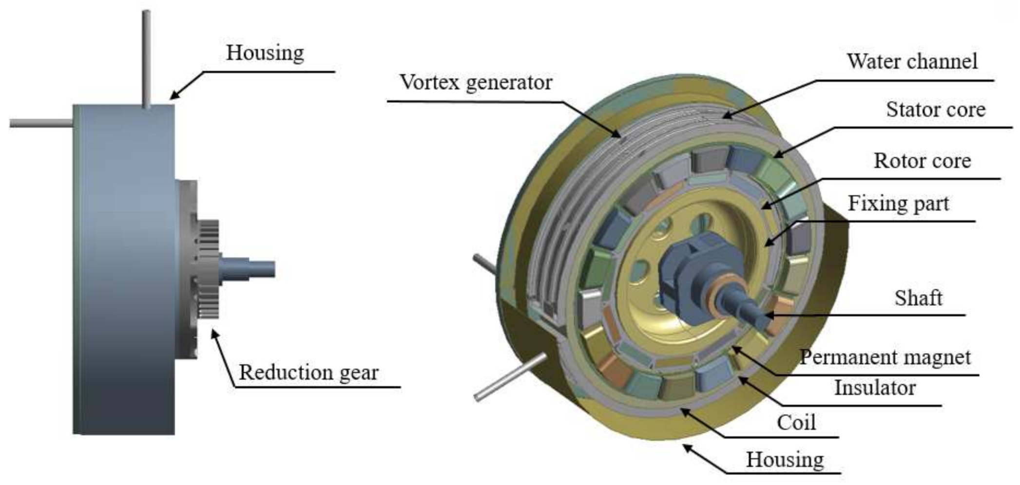
In this study, a 25 kW in-wheel motor for electric vehicles was designed as an enclosed structure for protection from the external environment and for the adoption of the water-cooling method. The in-wheel motor is mainly composed of fixed and rotating units. The rotating unit located inside the motor is composed of the rotor core, permanent magnet, shaft, and other parts, and the external fixed unit is composed of the housing, coil, insulator, stator core, and other parts. As shown in Figure 1, the in-wheel motor consists of the shaft, rotor core, permanent magnet, insulator, stator core, and housing in the order moving from the core towards the outside. The reduction gear is attached at the front along with the front cover.
As shown in Figure 2, the water channel for water cooling used in this study was installed between the stator core and the housing. The external portion of the water channel was designed with a 10 mm height and a 50 mm width to allow the channel to be installed between the stator core and the housing. Laminar flow could proceed in a spiral-type water channel with multiple layers. Thus, the water channel was designed as an elbow type to increase the turbulent flow and the thermal performance. If the cross-sectional width decreases to 10 mm or less, water channels with a rectangular cross-section experience a sudden pressure loss; to prevent such a pressure loss, the model was designed as a 15 mm, three-pass structure [21]. Therefore, the external thickness and inner height of the cross-section were set as 2 and 6 mm, respectively, excluding the thickness of the external shape. The rectangular-shaped flow cross-section corner was rounded to reduce the unnecessary pressure loss. The coolant was injected through the inlet; after the heat exchange process within the motor, it was discharged through the outlet.
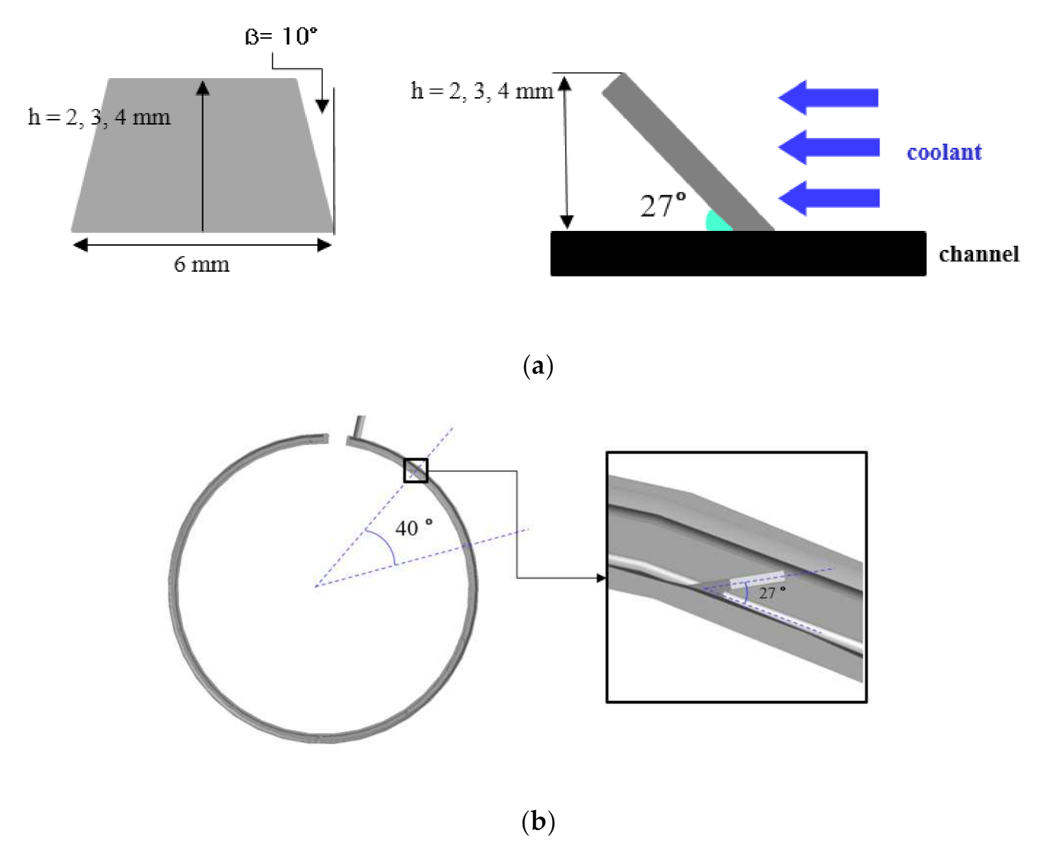
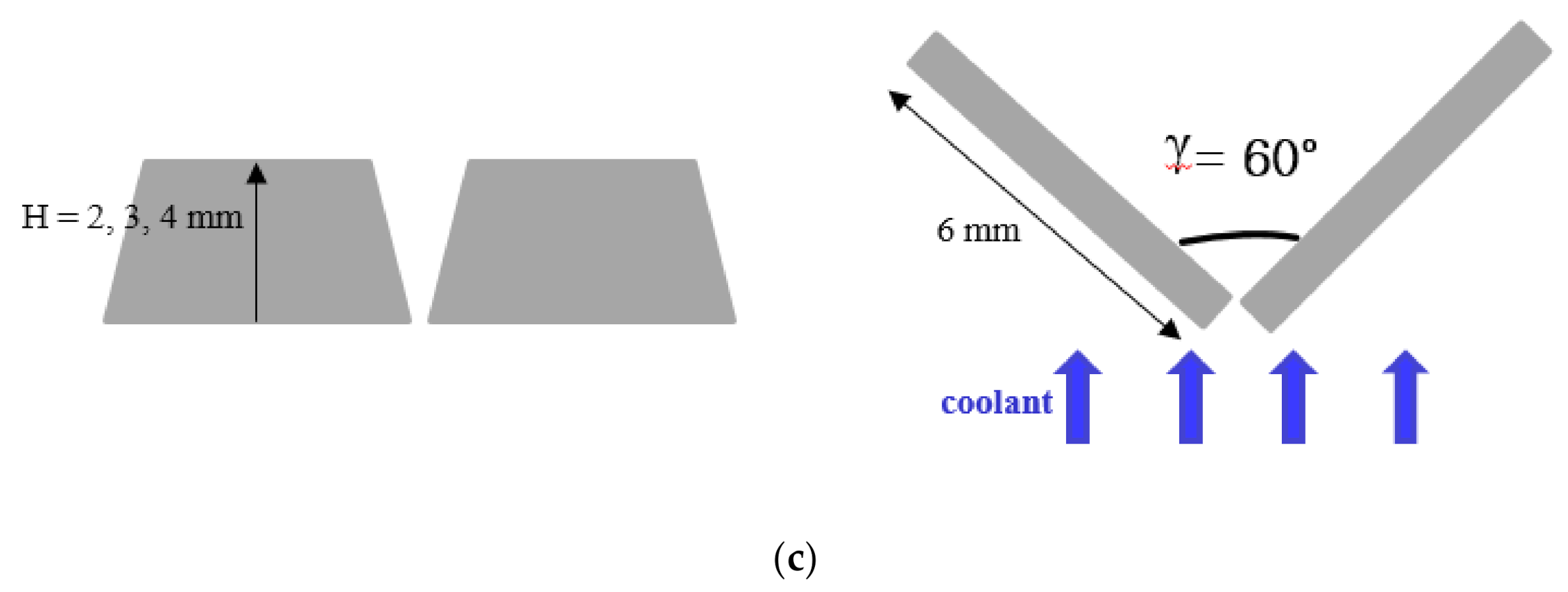
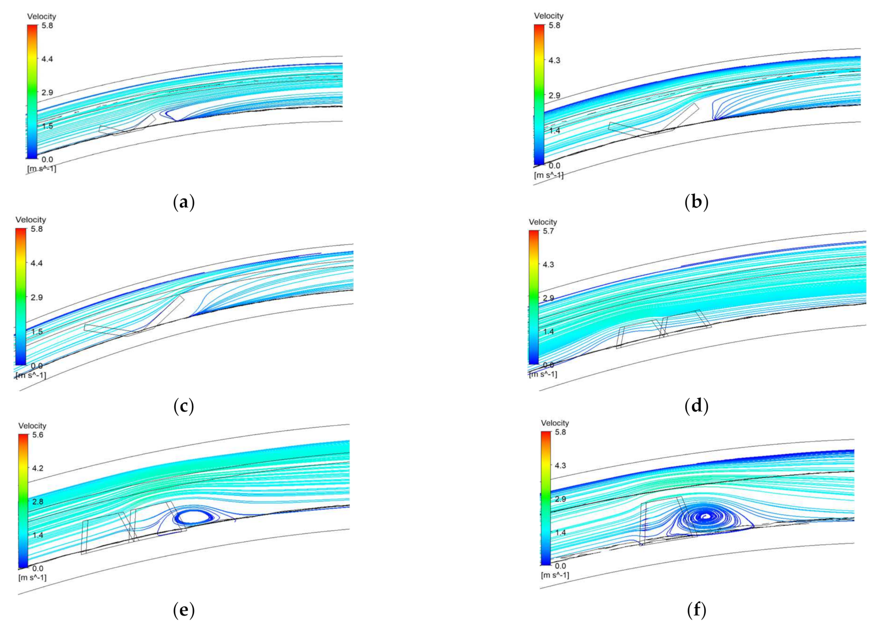
Of the two selected models, one was a simple, single-type vortex generator, and the other was a pair-type vortex generator. These models were chosen to examine the cooling effect of the in-wheel motor according to the application of the vortex generator in the water channel. As shown in Figure 3a, the trapezoidal vortex generator was installed at an angle of attack of 27° in the water channel with a single-type vortex generator, which generated hairpin vortices to sustain the turbulence. The pair of counter-rotating vortices, due to the trapezoidal shape, increased the flow mixing effect, from which a greater turbulence effect could be expected [22,23]. The angle of attack did not significantly affect the thermal performance; however, to obtain manufacturing margin considering a pressure drop for water pump specifications, it was set at 27°. In addition, better thermal performance can be expected because the trapezoidal vortex generator shows a flow similar to that installed in a complex type of vortex generator [24]. The base of the trapezoidal shape was 6 mm, and the side angle β was 10°. Flow analysis was performed to determine the height, h, corresponding to the pressure drop conditions. The base of the trapezoidal shape was 6 mm, and the side angle β was 10°. Flow analysis was performed to determine the height, h, corresponding to the pressure drop conditions. As shown in Figure 3b, the vortex generator was installed inside the cooling channel at a 40° angular pitch, and a total of 27, with nine for each pass. As shown in Figure 3c, a pair of trapezoidal vortex generators with height, H, were arranged in the water channel with a pair-type vortex generator. Flow analysis was performed to determine the suitable H for the pressure drop conditions. To increase the turbulence effect, the angle γ between the pair, with reference to the opposite direction of the flow, was determined as 60°. The optimal heights of the vortex generators under the pressure drop conditions were determined from the flow analysis. The corresponding results are presented in Figure 4. Based on these results, the optimal heights for the models with the applications of a single-type vortex generator and a pair-type vortex generator were determined to be 4 and 3 mm, respectively. As presented in Table 1, the values presented in the 25 kW air-cooled in-wheel motor for electric vehicles were used for the major components of the motor, excluding the water channel [8], and 6061 aluminum was used for the 30 kW water-cooled in-wheel motor for the water channel [20]. In addition, a fluid mixed with 1:1 ethylene glycol and water was used as the coolant flowing within the water channel to prevent freezing at low temperatures and to minimize internal corrosion.
The base speed and maximum speed of the in-wheel motor under the conditions of continuous rating were set as 1250 and 5000 RPM, respectively. As shown in Table 2, the external conditions were natural convection at room temperature, and the temperature of the working fluid coolant, which was injected at 7 LPM, was 65 °C in summer. Considering the pump performance at 7 LPM, the permitted pressure drop was set at 0.7 bar for the water pump for the coolant supply. The values of generated heat from the motors due to loss during operating conditions at 1250 and 5000 RPM are presented in Table 3.
2.2. Mathematical Background
The numerical analysis of the base and maximum speed conditions of the in-wheel motor was performed using Fluent (ver. 19.2). Three dimensions, a normal state, and an incompressible turbulent flow were the conditions assumed for the analysis. When effectively expressing the flow inside a water channel, there are some limitations in computation power; hence, the commonly used k-ε turbulent model was used for analysis. The k and ε values of this model were obtained through the following equations.
where Gk denotes the source term of the turbulent kinetic energy due to the average velocity gradient, and Gb denotes the turbulent kinetic energy generation due to buoyancy. The parameters σk and σε denote the turbulent Prandtl number, and μt denotes the turbulent viscosity. C1, C1ε, and C2 are the turbulence constants, and C1 is calculated using Equation (3). The parameter in Equation (3) is defined as the function of the turbulent kinetic energy k and the turbulent dissipation rate ε as shown in Equation (4). The parameter S in Equation (4) is expressed as the function of the average strain rate Sij as shown in Equation (5).
The moving reference frame technique was applied to simulate the rotational force of the rotating unit of the motor, and a coupled algorithm and pseudo-transient were used to increase the residual convergence. In addition, the enhanced wall treatment was used to ensure the validity of the analysis near the wall.
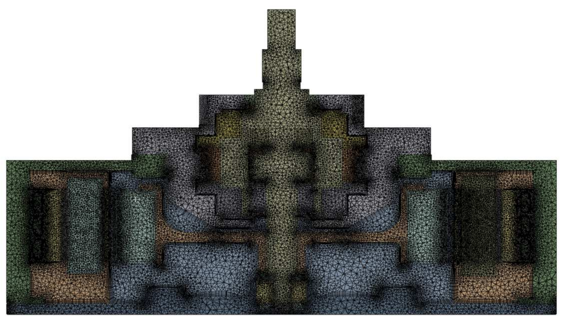
To shorten the duration of the analysis and improve convergence, the coil part wound with copper wires was simplified as a single solid shape, and the shape of the hole, which was used for fastening, was omitted. As shown in Figure 5, the mesh for analysis was structured as a tetrahedron so that the in-wheel motor model shape was comparable to the actual one. A prism mesh was used for the fluid area of the water channel to improve the accuracy of the analysis near the wall. The grid independence test was performed, and the optimum number of mesh elements was found to be 40 million.
The present numerical model was used to evaluate the performance of the 25 kW in-wheel motor for the evaluation of the cooling performance with modified grooved housing under ram air effect without using cooling channel in our previous study [8]. Using modified motor housing, the coil temperature was found to be 132.7 °C and 131.4 °C in numerical and experimental analyses, respectively [8], which depicts the good agreement between the experimental and numerical results and therefore, the present numerical model was deemed to be validated for use in the present analysis.
3. Results and Discussion
3.1. In-Wheel Motor with Simple Water Channel
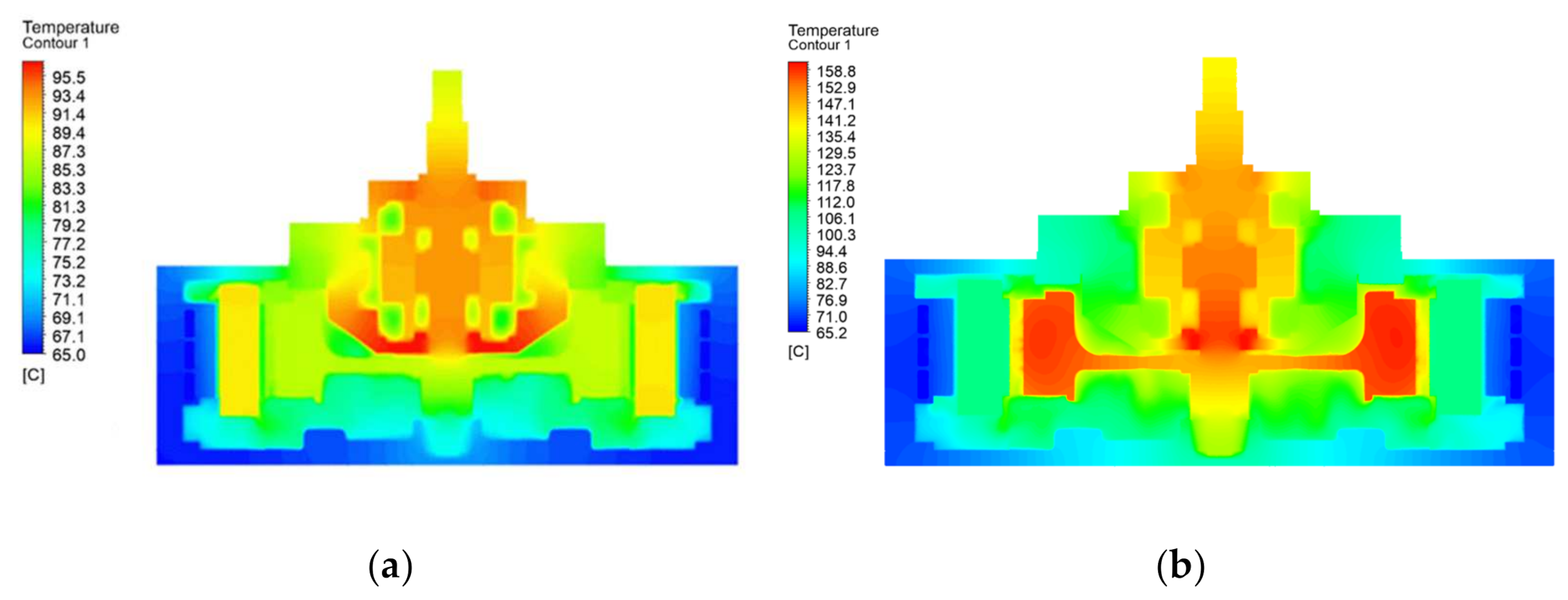
Table 4 shows the volumetric average temperature for each main component under a base speed of 1250 RPM and maximum speed of 5000 RPM in the analysis model for the in-wheel motor with a simple water channel. Figure 6 presents the temperature distribution in the motor shaft center cross-section with respect to rotational speed. The analysis results were considered to converge when the residual energy value was less than 10−6 and the residual value of the rest was less than 10−3. At a base speed of 1250 RPM, the temperatures at the fixed unit coil and rotating unit motor shaft were relatively high but significantly lower compared to the target temperature.
The heat generated by the coil travels through the stator and is delivered to the water channel and then to the housing, as shown in Figure 6a. Subsequently, it is released mainly through the coolant and partially through the external air through natural convection. In contrast, the heat generated from the rotor dissipates inside the motor due to the rotation, or it propagates to the shaft for discharge into the external air, where the cooling effect is relatively insignificant. As shown in the temperature distribution in Figure 6b, an overall higher temperature was observed at maximum-speed compared to that at base-speed conditions. Based on the properties of the interior permanent magnet motor, the amount of heat generated from iron loss and eddy current core loss under maximum-speed conditions was considerably higher than that under base-speed conditions. Thus, high-temperature distributions were observed at the rotor core and permanent magnet. In particular, the volumetric average temperature of the permanent magnet was 156.9 °C, which was associated with risks of irreversible demagnetization and motor performance degradation. Therefore, the cooling performance of the water channel needs to be improved for effective dissipation of motor heat.
3.2. In-Wheel Motor with Enhanced Water Channels
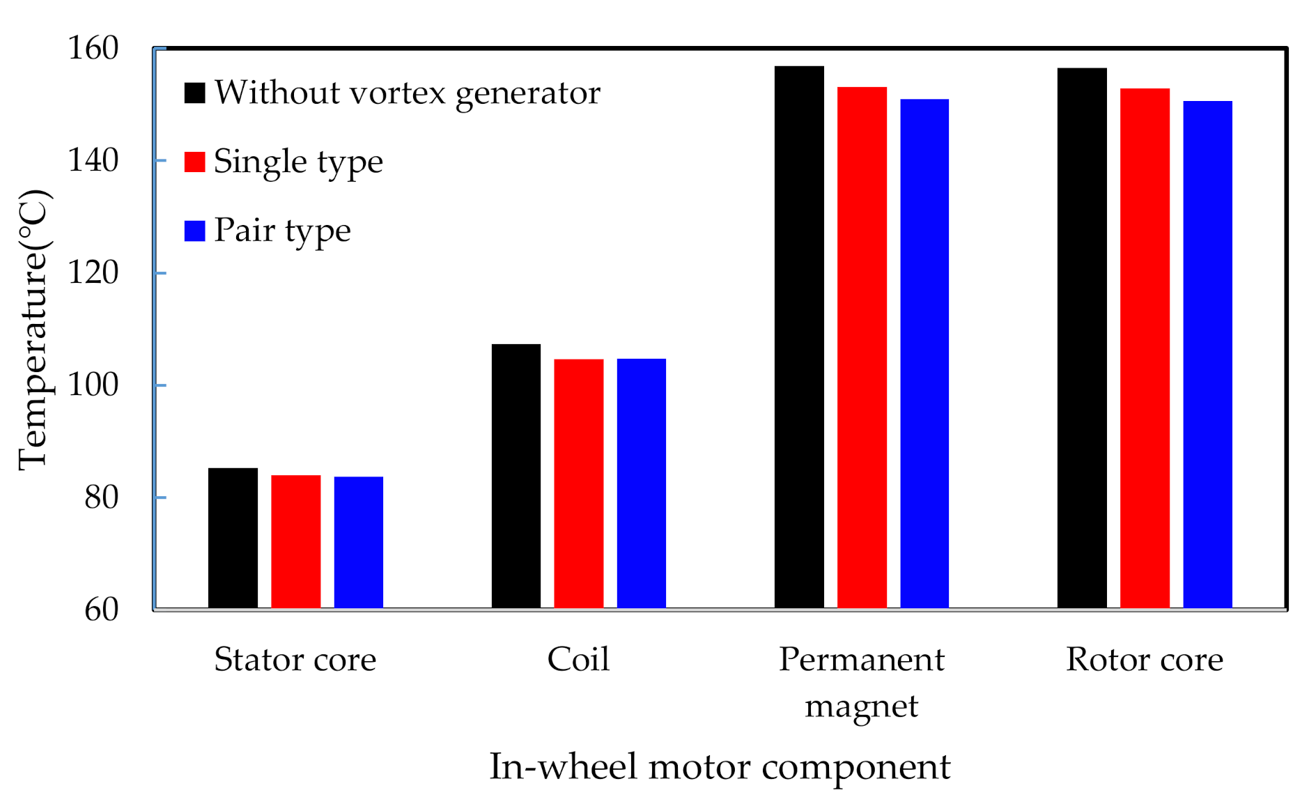
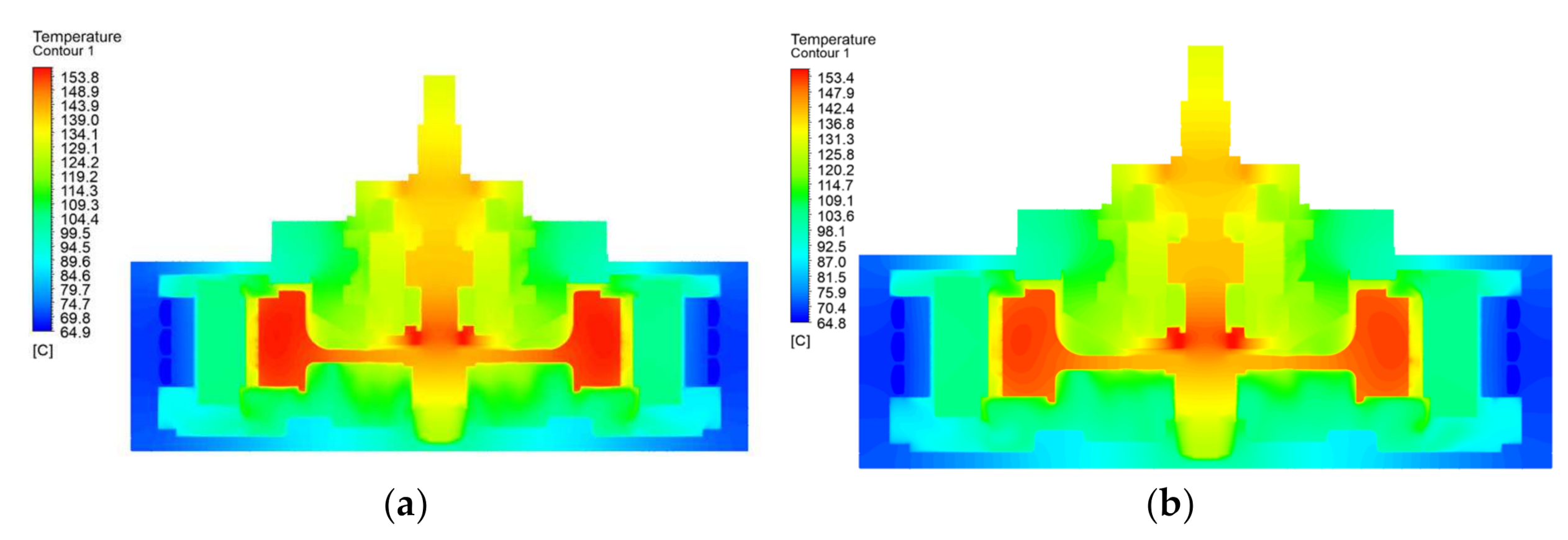
High temperatures were observed under the maximum-speed conditions of the in-wheel motor with a simple water channel; therefore, vortex generators were employed to decrease the temperature of the rotating unit, including the rotor core and permanent magnet. The average temperatures of the various components of the improved models with the single-type vortex generator and the pair-type vortex generator are summarized in Figure 7, and the temperature distribution of each model is provided in Figure 8. Compared to those in the simple model, the temperatures of (1) the stator core, which is in contact with the inner surface of the water channel and is the main cooling path of both the improved models, (2) the fixing unit insulator that successively cools down along with the stator core, and (3) the coil decreased in the improved models. The temperatures of the permanent magnet in the rotating unit are 153.1 and 150.9 °C, respectively. They decreased by 3.8 °C and 6.0 °C in the models with a single-type and a pair-type vortex generator, respectively. Table 5 shows 4.1% and 6.5% improvements in the in-wheel motor thermal performance, as defined based on the coolant entrance temperature, were achieved in the enhanced models with single-type and pair-type vortex generators, respectively. The areas of the heat transfer surfaces at the water channels of the models with the single-type and pair-type vortex generators were 0.0380 m2 and 0.0381 m2, which were 0.0015 m2 and 0.0016 m2 greater than that of the model without the vortex generator, respectively. Moreover, as vortices were intentionally generated and wake flows sustained, the convection heat transfer coefficients in the models with the single-type vortex generator and the pair-type vortex generator increased by 598 Wm−2 k−1 and 1511 Wm−2 k−1, respectively.
3.3. In-Wheel Motor Considering Ram Air Effect
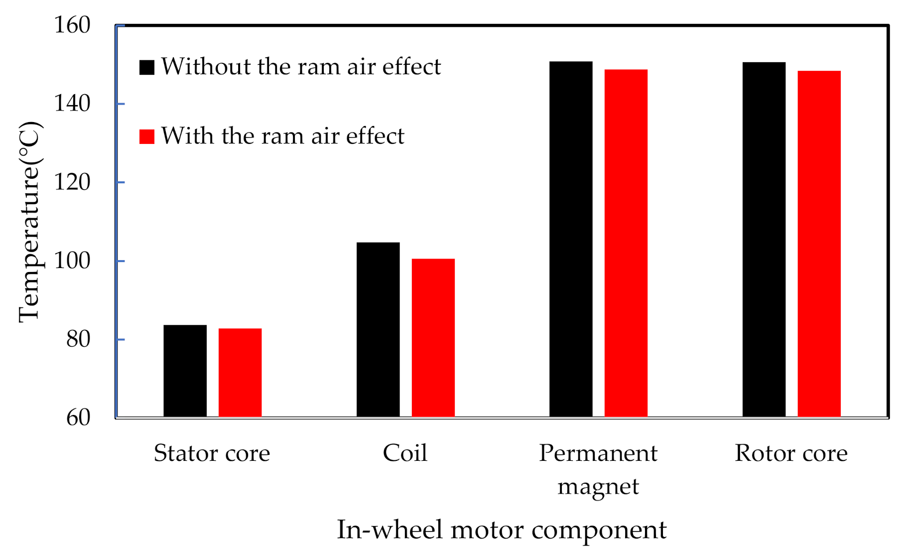
Until now, the external air of the in-wheel motor was assumed to flow according to natural convection, which led to an overestimation of the temperature. While the vehicle is running, ram air affects the cooling performance of the in-wheel motor drive. Under high-speed conditions, the housing is cooled by forced convection under the ram air effect, resulting in a higher convective heat transfer coefficient. Owing to the ram air stream observed in actual high-speed driving conditions, the in-wheel motor discharges heat through forced convection, which is considered to contribute to the motor exhibiting a lower temperature than estimated. In the maximum-speed conditions of 5000 RPM in a previous study that interpreted the impact of ram air on an in-wheel motor, the ram air entered the in-wheel motor at 13.2 m s−1 and 35° [9]. These were the average flow velocity and flow direction of the air around the housing when the vehicle was traveling at 120 km/h, which is similar under conditions wherein the rotation speed of the in-wheel motor is 5000 RPM. By setting the boundary conditions as 13.2 m s−1 and 35°, which are the ram air data corresponding to the high-speed condition of the in-wheel motor, and performing a precedence interpretation, the motor housing convection heat transfer coefficient of 31.2 W m−2 k−1 was obtained.
Among the enhanced models, for the model with the pair-type vortex generator, the convection heat transfer coefficient of 31.2 W m−2 k−1 obtained under maximum-speed conditions was applied when proceeding with the thermal flow analysis of the motor. This reflected the ram air effect under high-speed driving conditions. The average temperature of each component in the model with the pair-type vortex generator under the conditions of forced convection due to ram air is provided in Figure 9. The housing and shaft are cooled by forced convection owing to the ram air effect, and this effect cools the permanent magnet sequentially. Therefore, the temperature of the in-wheel motor was attained at a maximum permanent magnet temperature of 148.8 °C after a 2.1 °C decrease. A similar observation for the ram air effect as made by Kim et al. [8] in our previous work.
4. Conclusions
In this study, a water channel was designed to water-cool an in-wheel motor, and thermal flow analyses were performed at base and maximum speeds to determine the durability and performance of the in-wheel motor for electric vehicles. Accordingly, the thermal performance and temperature of each component were estimated. A vortex generator was installed inside the water channel to generate coolant vortices and induce wake flows to improve the thermal performance of the in-wheel motor.
(1) The in-wheel motor without a vortex generator, which only possessed a simple water channel, showed high temperatures at the permanent magnet and rotor core under maximum-speed conditions. In particular, the volumetric average temperature of the permanent magnet was 156.9 °C, which involved risks of irreversible demagnetization of the magnet and motor performance degradation. Therefore, the cooling performance of the water channel must be improved to effectively discharge the motor heat.
(2) Upon using vortex generators placed inside the water channels of the in-wheel motors, the temperature of the permanent magnet of the rotating unit in the models with a single-vortex generator and pair-type vortex generator decreased by 3.8 °C and 6.0 °C, corresponding to 4.1% and 6.5% improvements, respectively, in the in-wheel motor thermal performance based on the coolant entrance temperatures.
(3) Under high-speed driving conditions of the vehicle and maximum speed conditions of the in-wheel motor, upon considering the ram air effect, the maximum temperature of the permanent magnet decreased by 2.1 °C. The resulting maximum temperature of 148.8 °C satisfied the design limit of the in-wheel motor temperature.
Author Contributions
J.C.B. and H.R.C. performed the numerical analyses and drafted the manuscript. S.Y. discussed the results and edited the manuscript. S.C.K. organized the overall evaluation and reviewed the manuscript. All authors have read and agreed to the published version of the manuscript.
Funding
This work was supported by the National Research Foundation of Korea (NRF) with a grant funded by the Korea government (MSIT) (No.2020R1A2C1007068).
Institutional Review Board Statement
Not applicable.
Informed Consent Statement
Not applicable.
Data Availability Statement
Not applicable.
Conflicts of Interest
The authors declare no conflict of interest.
Nomenclature
| k | Turbulent kinetic energy |
| ε | Turbulent dissipation rate |
| μ | Viscosity |
| ρ | Density of a fluid or a solid |
| t | Time |
| Velocity | |
| Distance | |
| Dynamic viscosity |
References
- Foley, A.; Tyther, B.; Calnan, P.; Gallachoir, B.O. Impacts of Electric Vehicle charging under electricity market operations. Appl. Energy 2013, 101, 93–102. [Google Scholar] [CrossRef]
- Mokashi, I.; Khan, S.A.; Abdullah, N.A.; Azami, M.H.; Afzal, A. Maximum temperature analysis in a Li-ion battery pack cooled by different fluids. J. Therm. Anal. Calorim. 2020, 141, 2555–2571. [Google Scholar] [CrossRef]
- Jilte, R.; Afzal, A.; Panchal, S. A novel battery thermal management system using nano-enhanced phase change materials. Energy 2020, 219, 119564. [Google Scholar] [CrossRef]
- Kim, D.; Shin, K.; Kim, Y.; Cheon, J. Integrated Design of In-Wheel Motor System on Rear Wheels for Small Electric Vehicle. World Electr. Veh. J. 2010, 4, 597–602. [Google Scholar] [CrossRef] [Green Version]
- Nie, S.; Zhuang, Y.; Chen, F.; Wang, Y.; Liu, S. A method to eliminate unsprung adverse effect of in-wheel motor-driven vehicles. J. Low Freq. Noise Vib. Act. Control. 2018, 37, 955–976. [Google Scholar] [CrossRef] [Green Version]
- Lu, S.; Xu, X.; Chen, L.; Wang, F.; Wang, W. Coordinated Control of Electronic Differential and Differential Assist Steering for Electric Vehicle Driven by In-Wheel Motors. Chin. J. Mech. Eng. 2017, 53, 78–85. [Google Scholar] [CrossRef]
- Kim, M.-S.; Lee, K.-S.; Um, S. Numerical investigation and optimization of the thermal performance of a brushless DC motor. Int. J. Heat Mass Transf. 2009, 52, 1589–1599. [Google Scholar] [CrossRef]
- Kim, S.C.; Kim, W.; Kim, M.S. Cooling performance of 25 kW in-wheel motor for electric vehicles. Int. J. Automot. Technol. 2013, 14, 559–567. [Google Scholar] [CrossRef]
- Park, M.H.; Kim, S.C. Thermal characteristics and effects of oil spray cooling on in-wheel motors in electric vehicles. Appl. Therm. Eng. 2019, 152, 582–593. [Google Scholar] [CrossRef]
- Chen, Q.; Shao, H.; Huang, J.; Sun, H.; Xie, E.J. Analysis of Temperature Field and Water Cooling of Outer Rotor In-Wheel Motor for Electric Vehicle. IEEE Access 2019, 7, 140142–140151. [Google Scholar] [CrossRef]
- Fasquelle, A.; Laloy, D. Water cold plates cooling in a permanent magnet synchronous motor. IEEE Trans. Ind. Appl. 2016, 53, 4406–4413. [Google Scholar] [CrossRef]
- Rehman, Z.; Seong, K. Three-D Numerical Thermal Analysis of Electric Motor with Cooling Jacket. Energies 2018, 11, 92. [Google Scholar] [CrossRef] [Green Version]
- Huang, Z.; Nategh, S.; Lassila, V.; Alakula, M.; Yuan, J. Direct oil cooling of traction motors in hybrid drives. In Proceedings of the 2012 IEEE International Electric Vehicle Conference, Greenville, SC, USA, 4–8 March 2012. [Google Scholar] [CrossRef]
- Li, J.; Lu, Y.; Cho, Y.-H.; Qu, R. Design an Analysis of a Water-Cooled Axial Flux Permanent-Magnet Machine for Large Power Direct-Driven Applications. In Proceedings of the 2018 XIII International Conference on Electrical Machines (ICEM), Alexandroupoli, Greece, 3–6 September 2018; pp. 118–124. [Google Scholar] [CrossRef]
- Satrústegui, M.; Martinez-Iturralde, M.; Ramos, J.C.; Gonzalez, P.; Astarbe, G.; Elosegui, I. Design criteria for water cooled systems of induction machines. Appl. Therm. Eng. 2017, 114, 1018–1028. [Google Scholar] [CrossRef]
- Deriszadeh, A.; de Monte, F.; Villani, M.; Di Leonardo, L. Hydrothermal Performance of Ethylene Glycol and Water Mixture in a Spiral Channel for Electric Motor Cooling. In Proceedings of the 2019 21st European Conference on Power Electronics and Applications (EPE 19 ECCE Europe), Genova, Italy, 3–5 September 2019. [Google Scholar] [CrossRef]
- Yang, C.; Wang, H.; Niu, X.; Zhang, J.; Yan, Y. Design and Analysis of Cycling Oil Cooling in Driving Motors for Electric Vehicle Application. In Proceedings of the 2016 IEEE Vehicle Power and Propulsion Conference (VPPC), Hangzhou, China, 17–20 October 2016; pp. 1–6. [Google Scholar] [CrossRef]
- Liang, P.; Chai, F.; Shen, K.; Liu, W. Thermal design and optimization of a water-cooling permanent magnet synchronous in-wheel motor. In Proceedings of the 2019 22nd International Conference on Electrical Machines and Systems (ICEMS), Harbin, China, 11–14 August 2019. [Google Scholar] [CrossRef]
- Choi, G. Analysis and Experimental Verification of the Demagnetization Vulnerability in Various PM Synchronous Machine Configurations for an EV Application. Energies 2021, 14, 5447. [Google Scholar] [CrossRef]
- Luo, L.; Chang, J.; Wu, J.; Zhu, B.; Zheng, M.; Zhang, N. Design and Analysis of a Water-Cooling System in a New Yokeless and Segmented Armature Axial In-Wheel Motor for Electric Vehicles. J. Therm. Sci. Eng. Appl. 2021, 13, 1–12. [Google Scholar] [CrossRef]
- Cuiping, L.; Zhengwei, G.; Junhui, L.; Bing, Z.; Xiucui, D. Optimal design of cooling system for water cooling motor used for mini electric vehicle. In Proceedings of the 2017 20th International Conference on Electrical Machines and Systems (ICEMS), Sydney, Australia, 11–14 August 2017; pp. 1–4. [Google Scholar] [CrossRef]
- Gretta, W.J.; Smith, C.R. The Flow Structure and Statistics of a Passive Mixing Tab. ASME J. Fluids Eng. 1993, 115, 255–263. [Google Scholar] [CrossRef]
- Kwon, B.; Liebenberg, L.; Jacobi, A.M.; King, W.P. Heat transfer enhancement of internal laminar flows using additively manufactured static mixers. Int. J. Heat Mass Transf. 2019, 137, 292–300. [Google Scholar] [CrossRef]
- Jiang, Y.; Chen, B.; Duan, C.; Yan, X.; Wang, L. Flow and heat transfer characteristics in square channel with concave–convex vortex generators based on numerical simulations. Asia-Pac. J. Chem. Eng. 2021, 16, e2601. [Google Scholar] [CrossRef]
Figure 1.
Geometry of 25 kW in-wheel driving motor.

Figure 2.
Inlet, outlet, and section of simple water channel model with flow mechanism.

Figure 3.
Flow mechanism and variables of enhanced models with vortex generators: (a) Front view and side view of single-vortex generator; (b) side view of water channel with single-vortex generator; (c) Front view and top view of pair-type vortex generator.
Figure 3.
Flow mechanism and variables of enhanced models with vortex generators: (a) Front view and side view of single-vortex generator; (b) side view of water channel with single-vortex generator; (c) Front view and top view of pair-type vortex generator.


Figure 4.
Flow results according to height of enhanced models with vortex generators: (a) single type (h = 2 mm); (b) single type (h = 3 mm); (c) single type (h = 4 mm); (d) pair type (H = 2 mm); (e) pair type (H = 3 mm); (f) pair type (H = 4 mm).
Figure 4.
Flow results according to height of enhanced models with vortex generators: (a) single type (h = 2 mm); (b) single type (h = 3 mm); (c) single type (h = 4 mm); (d) pair type (H = 2 mm); (e) pair type (H = 3 mm); (f) pair type (H = 4 mm).

Figure 5.
Grid model of whole configuration.

Figure 6.
Temperature contour of in-wheel motor with simple water channel: (a) Base speed; (b) maximum speed.
Figure 6.
Temperature contour of in-wheel motor with simple water channel: (a) Base speed; (b) maximum speed.

Figure 7.
Comparison of average temperature of major parts of in-wheel motor with enhanced water channels.
Figure 7.
Comparison of average temperature of major parts of in-wheel motor with enhanced water channels.

Figure 8.
Temperature contour of enhanced models with each type of vortex generator: (a) Single-type vortex generator; (b) pair-type vortex generator.
Figure 8.
Temperature contour of enhanced models with each type of vortex generator: (a) Single-type vortex generator; (b) pair-type vortex generator.

Figure 9.
Comparison of average temperature of major parts of in-wheel motor considering the ram air effect.
Figure 9.
Comparison of average temperature of major parts of in-wheel motor considering the ram air effect.


Table 1.
Thermal properties of the in-wheel motor parts.
| Parts | Density | Specific Heat | Thermal Conductivity |
|---|---|---|---|
| kg m−3 | J kg−1 K−1 | W m−1 K−1 | |
| Bearing | 7805 | 460 | 27 |
| Coil | 8900 | 376 | 388 |
| Housing | 2698 | 896 | 180 |
| Insulator | 1090 | 1840 | 0.41 |
| Permanent magnet | 7700 | 440 | 9 |
| Rotor core | 7600 | 4700 | 24 |
| Stator core | 7600 | 470 | 24 |
| Reduction gear | 7861 | 473 | 42.6 |
| Water channel | 2700 | 903 | 166.9 |
Table 2.
Boundary conditions.
| Parameter | Value |
|---|---|
| Ambient temp. | 20 °C |
| Ambient heat transfer coefficient | 13 W m−2 k−1 |
| Coolant temp. | 65 °C |
| Flow rate of coolant | 7 LPM |
| Motor power | 25 kW |
| Motor speed | 1250 RPM, 5000 RPM |
Table 3.
Values of generated heat.
| Speed | Iron Loss (W) | Copper Loss (W) | Eddy Current Loss (W) | Mechanical Loss(W) | Reduction Gear (W) | Torque (N-m) |
|---|---|---|---|---|---|---|
| 1250 RPM | 94.9 | 257.4 | 15.2 | 38.9 | 268 | 76.5 |
| 5000 RPM | 566.6 | 262.9 | 192.7 | 295.9 | 262 | 200 |
Table 4.
Average temperature of each part of in-wheel motor with simple water channel.
| Parts | Temperature (°C) | ||
|---|---|---|---|
| 1250 RPM | 5000 RPM | ||
| Housing | 69.4 | 75.7 | |
| Stator core | 73.7 | 85.3 | |
| Fixed parts | Coil | 90.2 | 107.3 |
| Insulator | 83.9 | 99.8 | |
| Reduction gear | 89.9 | 113.1 | |
| Shaft | 91.7 | 146.2 | |
| Rotating parts | Rotor core | 86.4 | 156.6 |
| Permanent magnet | 86.5 | 156.9 | |
Table 5.
Comparison of the thermal performance of the simple and enhanced models.
| Parameter | Simple Model without Vortex Generator | Enhanced Model with Single-Type Vortex Generator | Enhanced Model with Pair-Type Vortex Generator |
|---|---|---|---|
| Water channel inner surface area (m2) | 0.0365 | 0.0380 | 0.0381 |
| Heat transfer coefficient at inner surface of coolant (Wm−2 k−1) | 6527 | 7125 | 8038 |
| Thermal performance (%) | - | 4.1 | 6.5 |
Publisher’s Note: MDPI stays neutral with regard to jurisdictional claims in published maps and institutional affiliations. |
© 2022 by the authors. Licensee MDPI, Basel, Switzerland. This article is an open access article distributed under the terms and conditions of the Creative Commons Attribution (CC BY) license (https://creativecommons.org/licenses/by/4.0/).
Share and Cite
MDPI and ACS Style
Bae, J.C.; Cho, H.R.; Yadav, S.; Kim, S.C. Cooling Effect of Water Channel with Vortex Generators on In-Wheel Driving Motors in Electric Vehicles. Energies 2022, 15, 722. https://0-doi-org.brum.beds.ac.uk/10.3390/en15030722
AMA Style
Bae JC, Cho HR, Yadav S, Kim SC. Cooling Effect of Water Channel with Vortex Generators on In-Wheel Driving Motors in Electric Vehicles. Energies. 2022; 15(3):722. https://0-doi-org.brum.beds.ac.uk/10.3390/en15030722
Chicago/Turabian StyleBae, Jae Chang, Hyeon Rae Cho, Saurabh Yadav, and Sung Chul Kim. 2022. "Cooling Effect of Water Channel with Vortex Generators on In-Wheel Driving Motors in Electric Vehicles" Energies 15, no. 3: 722. https://0-doi-org.brum.beds.ac.uk/10.3390/en15030722
Note that from the first issue of 2016, this journal uses article numbers instead of page numbers. See further details here.