
A Prediction Method for Hydrocarbon Distribution Associated with Fault-Shale Caprock Configuration Leakages

College of Earth Science, Northeast Petroleum University, Daqing 163318, China
Energies 2022, 15(8), 2867; https://0-doi-org.brum.beds.ac.uk/10.3390/en15082867
Submission received: 3 March 2022
/
Revised: 7 April 2022
/
Accepted: 11 April 2022
/
Published: 14 April 2022
(This article belongs to the Special Issue Shale Oil and Gas Accumulation Mechanism)
Abstract
:A prediction method of hydrocarbon distribution associated with fault-shale caprock configuration leakages is established through superposing hydrocarbon distribution at deep basin fault-shale caprock configuration leakages, and conducting faults to understand distribution of shallow reservoirs of “lower generation, upper accumulation” in petroliferous basins based on fault-shale caprock configuration leakage mechanism. Prediction of hydrocarbon distribution at the Ed-3 Member in the south of the northern Dagang area of Bohai Bay Basin was used to demonstrate the application of the proposed method. Results show that predicted oil and gas at the Ed-3 Member are mainly distributed in the middle of the north and in the middle of the south edge, where fault-shale caprock configuration leakages in the middle of the Sha-1 Member contributed positively to oil and gas migration from the hydrocarbon reservoir at deep basin to the shallow reservoirs. The prediction matches well with discovered oil and gas in this area, proving the validity of this method.
1. Introduction
Oil and gas exploration practices suggest that hydrocarbon supply plays an important role in the development and distribution of shallow reservoirs of “lower generation, upper accumulation”, where hydrocarbon migration from the deep to the shallow is significantly controlled by fault-shale caprock configurations. For instance, traps can be effectives ones when they are located at or close to the fault-shale caprock configuration leakages. Hence, accurately predicting positions of fault-shale caprock configuration leakages is critical for shallow oil and gas exploration in petroliferous basins.
Predecessors have studied and discussed oil and gas leakage at fault-shale caprock configurations, which can be summarized as follows. Firstly, oil and gas leakage can occur at fault-shale caprock configurations only when faults are continuously or connected with each other at mudstone shale caprocks [1,2,3,4,5,6,7,8]. Secondly, oil and gas leakage can occur when shale caprock faulted-contact thickness (the difference between shale caprock thickness and fault throw) is lower than the maximum value required for connecting discontinued faults at shale caprocks, which can be used to predict fault-shale caprock configuration leakages [9,10,11,12,13,14]. However, primary positions of upward fault-shale caprock configuration leakages are poorly investigated [15,16,17,18,19], and no work has been performed to superimpose fault-shale caprock configuration leakages, predominant pathways in fault systems, and hydrocarbon distribution at deep basin to seek fault-shale caprock configuration leakages at shallow basin, which brings risks to shallow oil and gas exploration. Therefore, investigating prediction method for fault-shale caprock configuration leakages is of great significance for correctly understanding the distribution of shallow oil and gas reservoirs of “lower generation, upper accumulation” in petroliferous basins, and thus in guiding oil and gas exploration.
2. Mechanism and Distribution of Fault-Shale Caprock Configuration Leakages
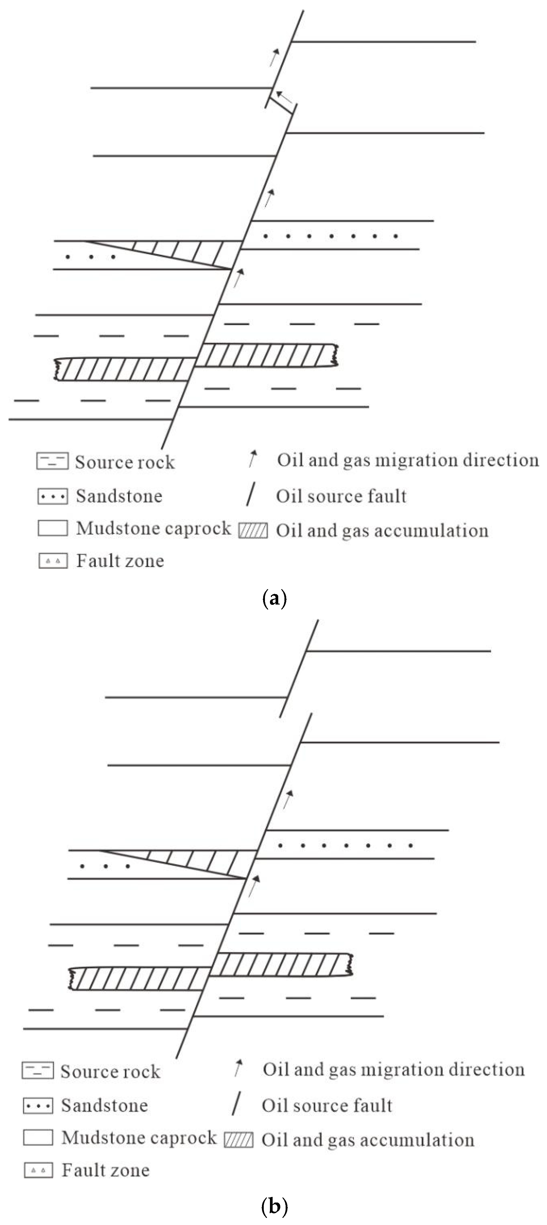
Oil and gas can migrate to the shallows through fault-shale caprock configurations when faults are connected at shale caprocks, as shown in Figure 1a. On the contrary, oil and gas cannot migrate to the shallows via faults (Figure 1b).
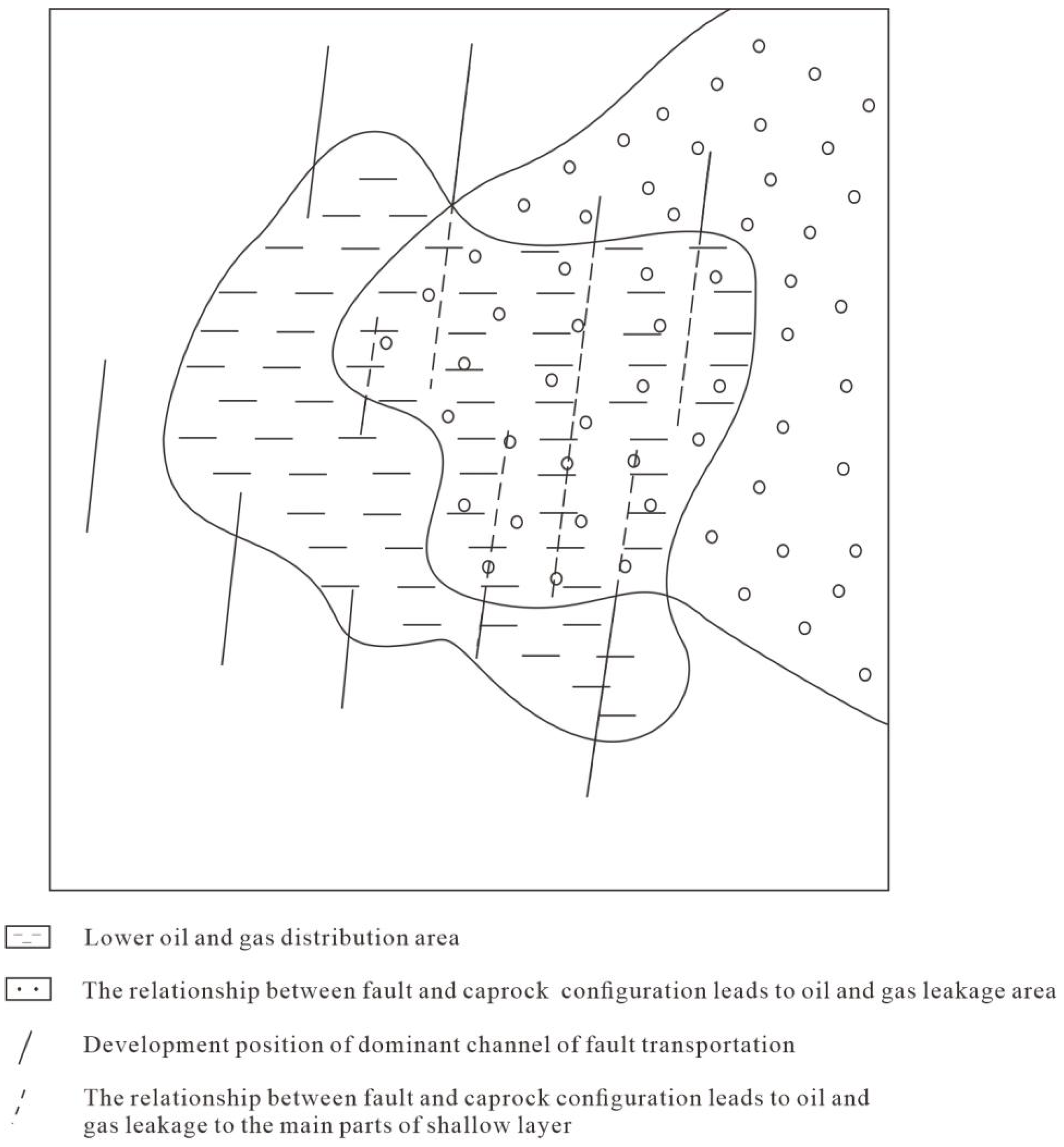
Oil and gas distributions at shallow basin are commonly coupled by hydrocarbon distribution at deep basin, fault-shale caprock configuration leakage, and predominant pathways in fault systems (Figure 2).
3. Prediction Methods for Hydrocarbon Distribution Associated with Fault-Shale Caprock Configuration Leakages
As shown in the analysis above depicting a hydrocarbon reservoir at deep basin, fault-shale caprock configuration leakage and conducting faults are essential to predict hydrocarbon distribution associated with fault-shale caprock configuration leakages.
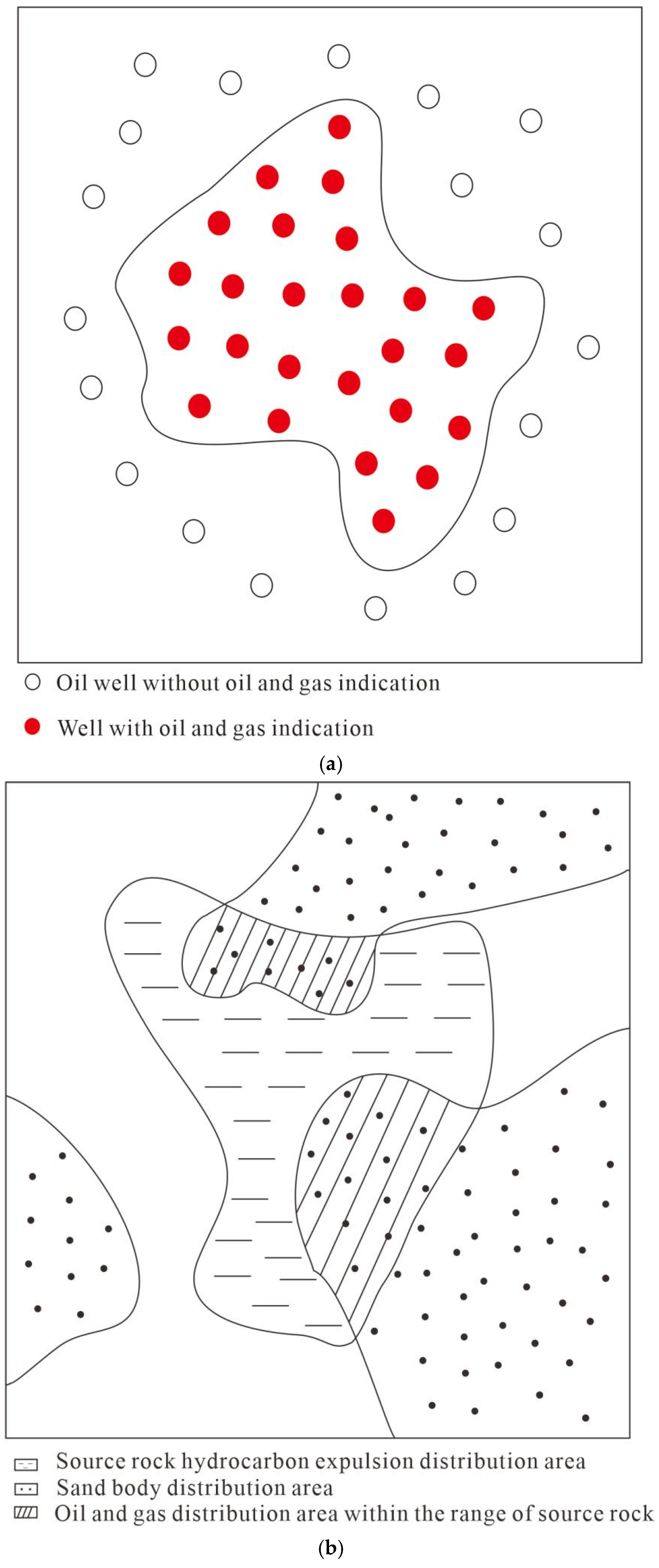
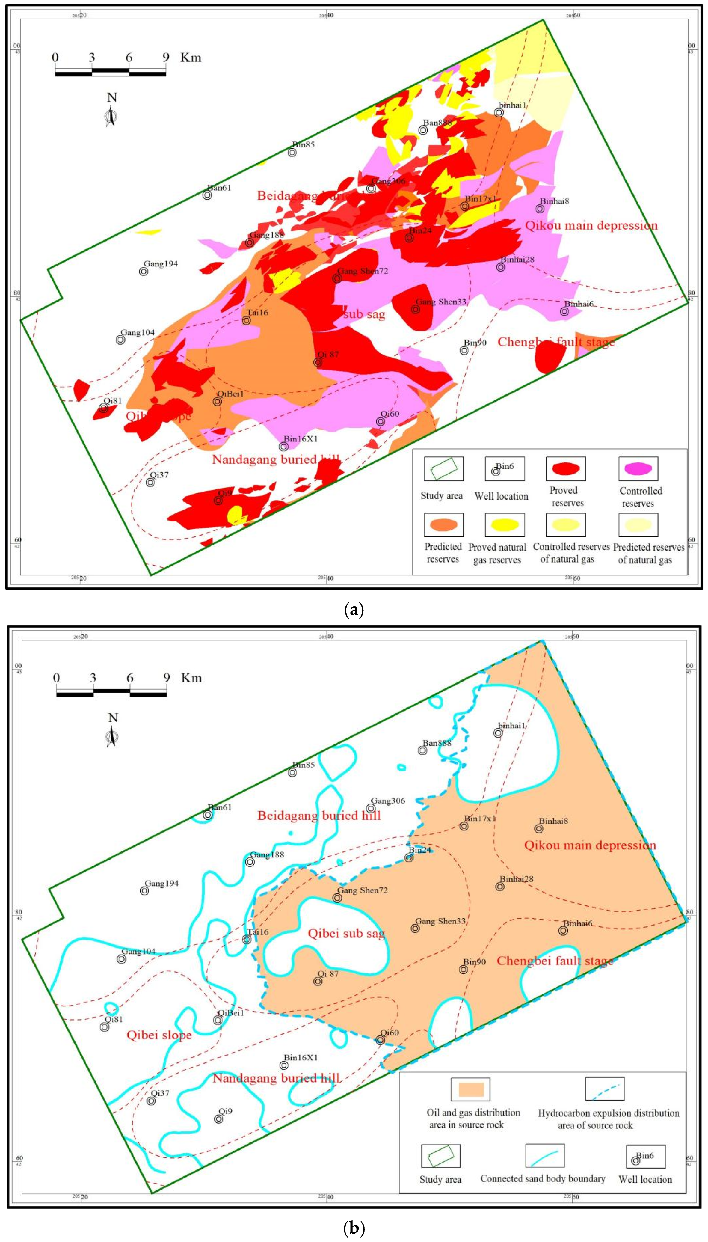
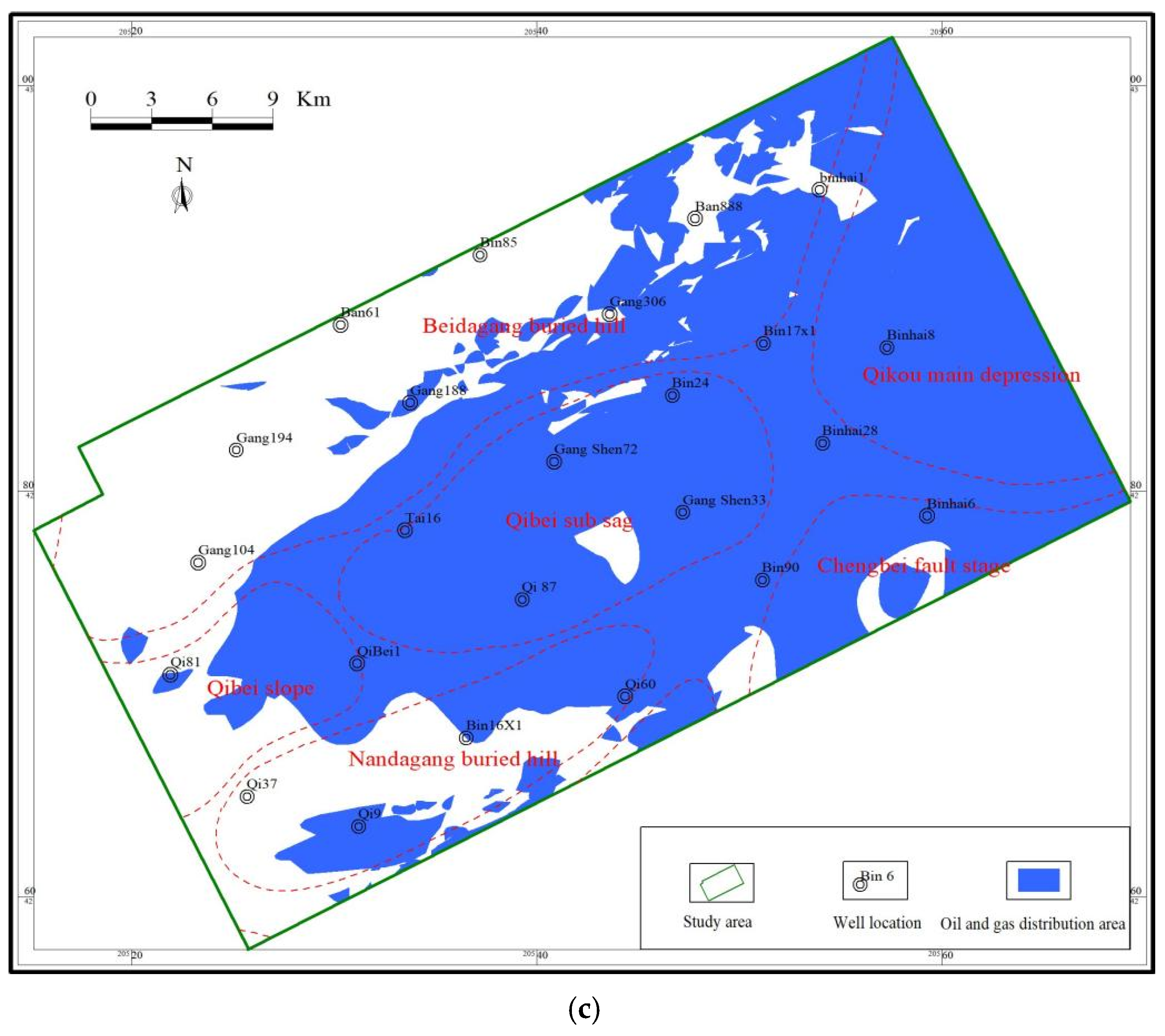
Hydrocarbon distribution at deep basin can be divided into two units, i.e., hydrocarbon outside source rocks, and hydrocarbon within source rocks, while the former can be determined with drilling data (Figure 3a). It is approximated that hydrocarbon distribution within source rocks is controlled by connected sand bodies within source rocks, because these sand bodies have the advantage of preferentially capturing oil and gas. Hydrocarbon expulsion thresholds can be identified based on a method proposed by reference [20], with variations of (S1 + S2)/TOC with depth, which can be further used to map distribution of expelled hydrocarbon (Figure 3b). Sand ratios within source rocks can be acquired with drilling data, and the minimum value required for sandstone connection [21] can be used to describe the distribution of connected sand bodies (Figure 3b). Distributions of expelled hydrocarbon and connected sand bodies can be superposed to determine hydrocarbon distribution within source rocks (Figure 3b). Hydrocarbon distributions outside and within source rocks can be superposed to identify hydrocarbon distributions at deep basin (Figure 2).
Current fault throws at shale caprocks, and shale caprock thickness, can be acquired with drilling and seismic data. After that, fault throw and shale caprock thickness during hydrocarbon accumulation can be restored with the maximum fault throw subtraction method [22] and the palaeo thickness restoration method [23]. The shale caprock faulted-contact thickness then can be calculated by subtracting the palaeo fault throw from the palaeo shale caprock thickness. The maximum shale caprock faulted-contact thickness required for connecting discontinuous faults in the shale caprocks can be determined with the method in reference [24]. Finally, the fault shale caprock configuration leakages can be identified through comparing the shale caprock faulted-contact thickness with the maximum shale caprock faulted-contact thickness (Figure 2).
Conducting faults are those both connecting source rocks and reservoirs, and faulting during oil and gas accumulation, which can be determined with seismic data. Fault throws of conducting faults at reservoirs also can be determined with seismic data, and corresponding palaeo fault throws during oil and gas accumulation can be restored via the maximum fault throw subtraction method [22]. Palaeoactivity rate of faults can be calculated through dividing palaeo fault throws by fault activity periods. The minimum activity rate required for faults to migrate oil and gas in the study area can be determined with the method from reference [25]. After that, development positions of conducting faults can be obtained by comparing the activity rate of faults at the study area and the required minimum value (Figure 2).
Oil and gas distribution associated with fault-shale caprock configuration leakages can be mapped through superposing hydrocarbon distribution at deep basin, fault-shale caprock configuration leakages, and conducting faults (Figure 2).
4. Application Example
Taking the south of the northern Dagang area at Qikou Sag in Huanghua Depression of Bohai Bay Basin as an example, this paper used the above method to predict oil and gas leakage from the middle part of the first Member of the Shahejie Formation (Sha-1 Member) to the third Member of Dongying Formation (Ed-3 Member). Predictions were compared with oil and gas discovered in the Ed-3 Member to verify the feasibility of this method.
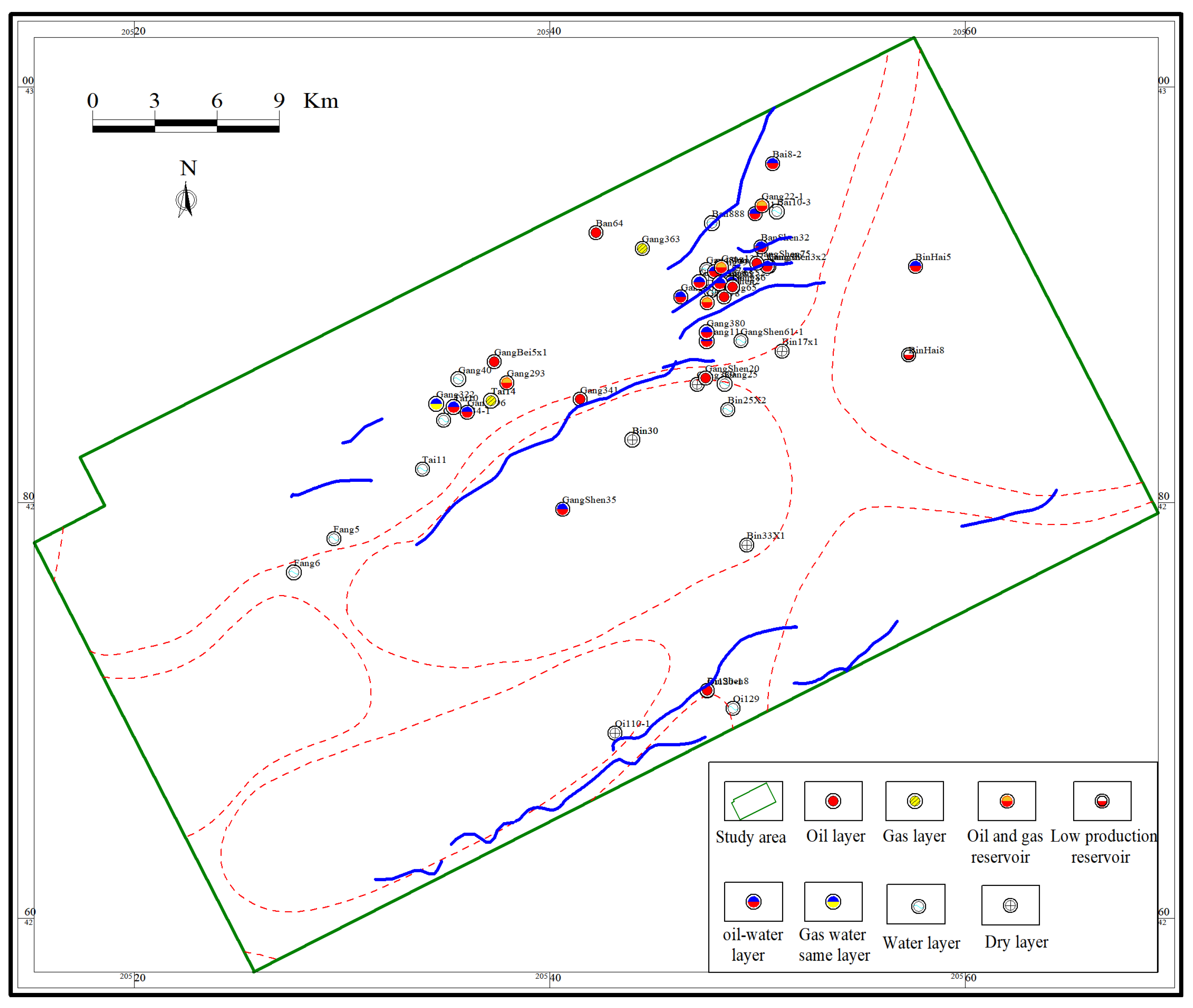
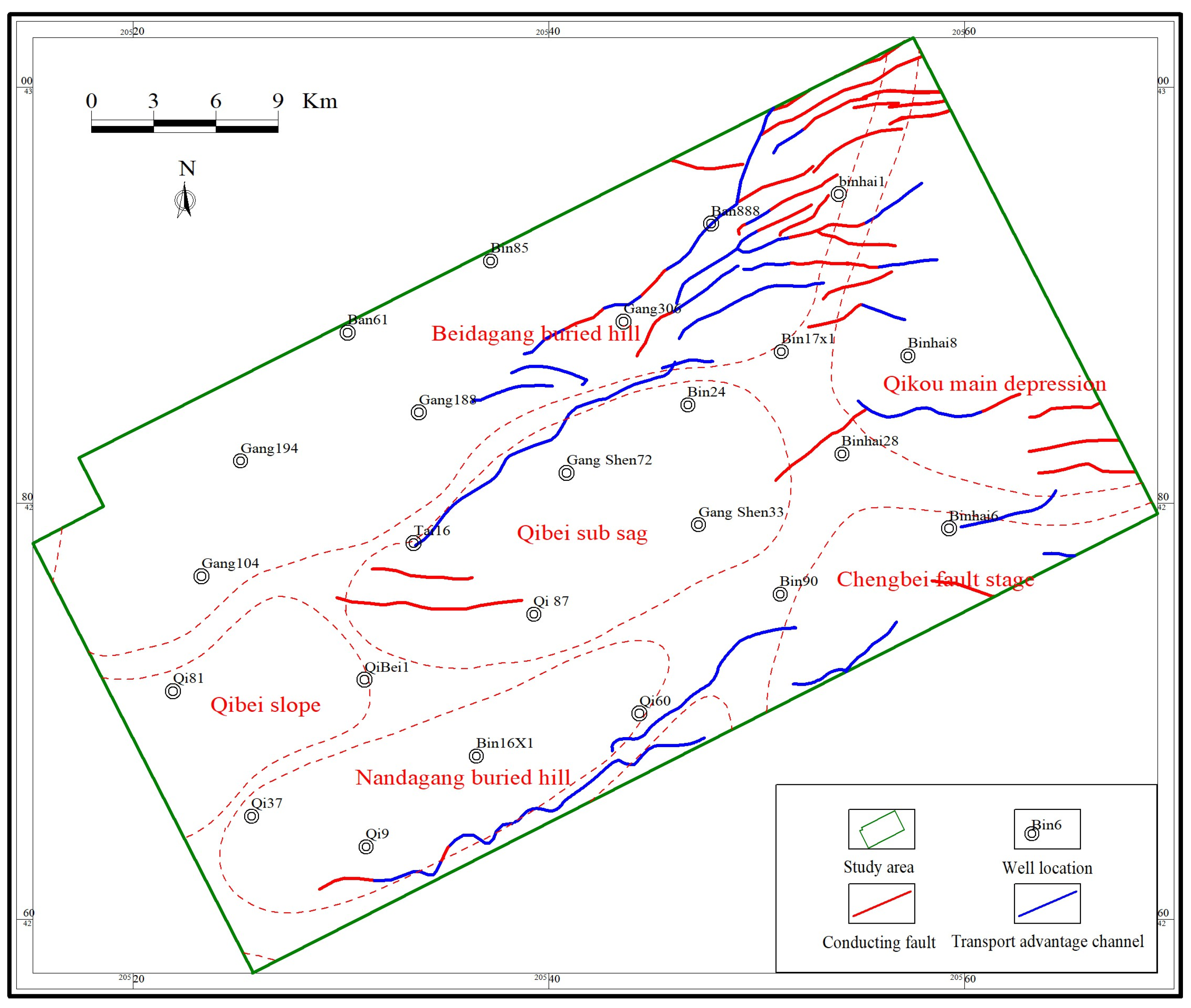
The south of the northern Dagang area is located in the central and northern parts of Qikou Sag. Structurally, it can be divided into the Qibei sub-sag, the south Dagang buried hill, the southern and central part of north Dagang buried hill, the north of Qibei slope, the southwest of Qikou sag, and the northwest of Chengbei fault-step zone (Figure 4). The strata drilled in this area mainly include the Palaeogene (Kongdian Formation, Shahejie Formation and Dongying Formation), the Neogene (Guantao Formation and Minghuazhen Formation), as well as the Quaternary. Currently, discovered oil and gas are mainly distributed at Shahejie Formation, with a small proportion at Dongying Formation and Guantao Formation, which was mainly derived from the Es-3 Member. The oil and gas generated by the Es-3 source rocks can be accumulated at the Ed-3 Member, which have to migrate through the regional shale caprock at the middle part of the Sha-1 Member. Figure 4 shows that oil and gas discovered at the Ed-3 Member at the south of the northern Dagang area are mainly distributed in the north, with a minor amount in the middle of the south edge. Besides traps and sand bodies, it is mainly controlled by fault-shale caprock configuration leakages at the Sha-1 Member. Therefore, accurately predicting oil and gas distribution at the Ed-3 Member associated fault-shale caprock configuration leakages is critical for oil and gas exploration in the south of the northern Dagang area.
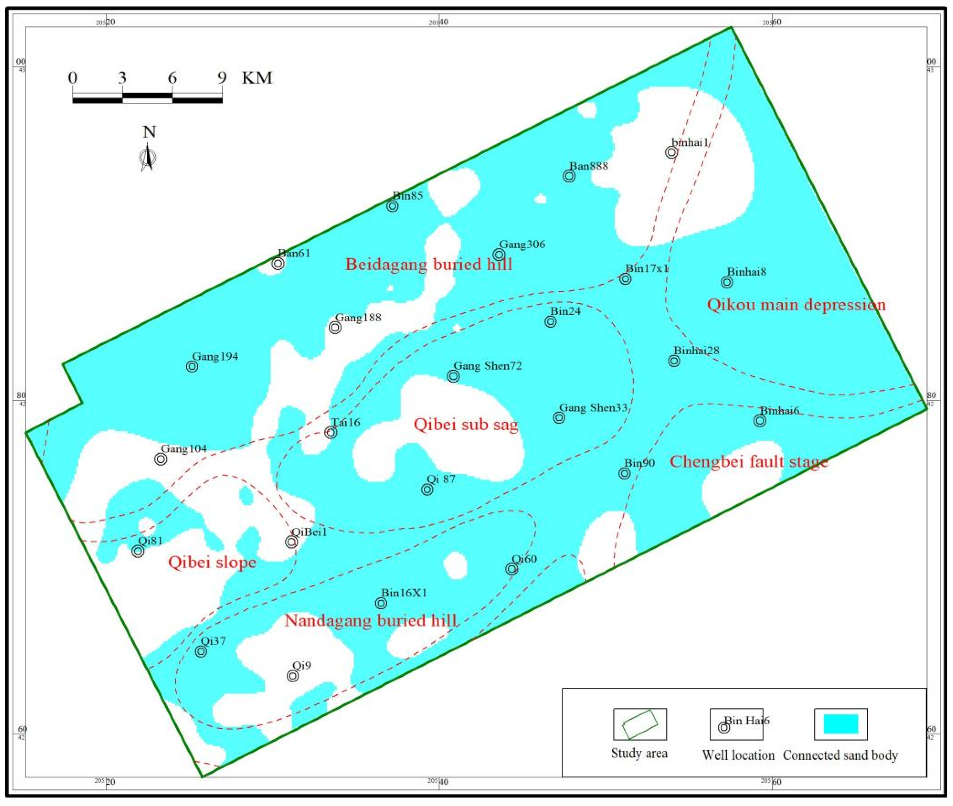
Drillings into reservoirs below the Ed-3 Member are enveloped to represent hydrocarbon outside the source rocks in the south of the northern Dagang area (Figure 5a), which is mainly distributed in most areas except the surrounding area. The hydrocarbon expulsion threshold of the Sha-3 source rocks in the south of the northern Dagang area is about 3500 m, which is used to determine the hydrocarbon expelled distribution at the south of the northern Dagang area. Figure 5b shows that expelled hydrocarbon is mainly distributed in the eastern and central parts. The sand ratios of Sha-3 source rocks are determined with drilling data, while the high is mainly distributed in the east, the north, and the southwest, with values up to 30%. These values decrease to zero towards the northeast, the southwest, and the north. The minimum sand ratio required for sand body connection at the Qikou Sag is about 15% [21], which is used to determine the distribution of connection in the Sha-3 source rocks in the south of the northern Dagang area (Figure 6). Most sand bodies within Sha-3 source rocks are connected, except sand bodies at the northeast, the southern edge, and the central part of the west. The distributions of expelled hydrocarbon and connected sand bodies are superposed to map hydrocarbon accumulations within source rocks (Figure 5b). After that, the hydrocarbon accumulations outside and within source rocks are enveloped to describe distribution of hydrocarbon reservoirs below the Ed-3 Member. Figure 5c shows that hydrocarbon is widely distributed in the south of the northern Dagang area, except local positions, e.g., the north, the west, and the southwest edge.
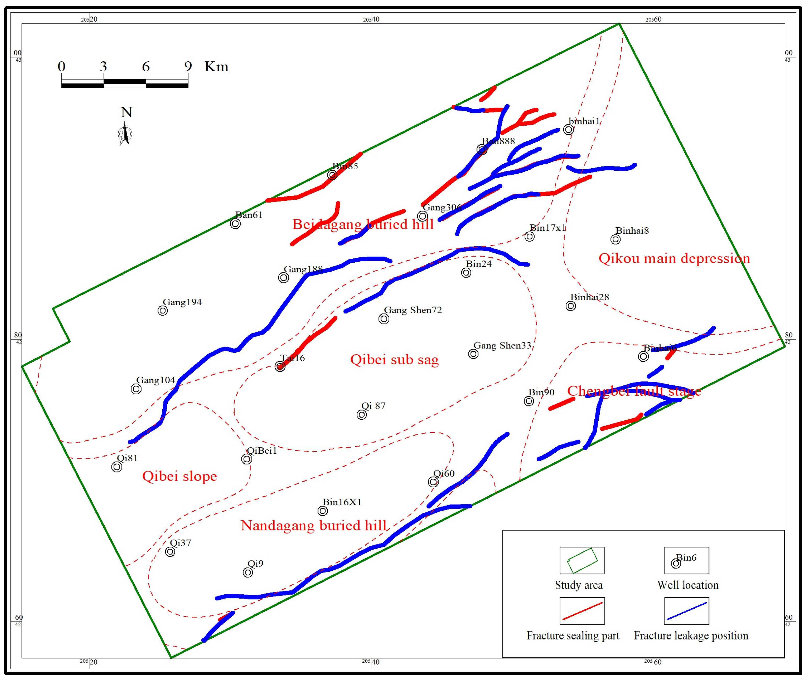
Faults connecting the Sha-3 source rocks and the Ed-3 Member in the south of the northern Dagang area are identified based on seismic data, while active ones during hydrocarbon accumulation, i.e., middle to later Minghuazhen period [26,27], are considered as conducting faults. Figure 7 shows that conducting faults at the Ed-3 Member in the south of the northern Dagang area are mainly distributed in the east, with minor faults in the north and in the south. Fault throws at the Sha-1 shale caprocks and thickness of corresponding shale caprocks are acquired with 3D seismic data, which are used to restore palaeo fault throws and palaeo shale caprock thickness during the middle to later Minghuazhen period [22,23]. Subsequently, the palaeo fracture thickness is calculated by subtracting the palaeo fault throw from the palaeo shale caprock thickness. Fault-shale caprock configuration leakages in the middle part of Sha-1 Member are determined, with the maximum shale caprock faulted-contact thickness required for connecting discontinuous faults at shale caprocks in Qikou Sag of 170–180 m [24], which is mainly distributed in the middle of the north and the south edge.
Current fault throws of conducting faults at the Ed-3 Member in the south of the northern Dagang area are calculated with 3D seismic data, which is used to restore ancient fault throws during oil and gas accumulation period [22], e.g., the middle and late Minghuazhen period. They are then divided by fault activity period to determine the paleoactivity rate. Predominant pathways in fault systems at the Ed-3 Member are determined using the required minimum fault activity rate at Qikou Sag of 4 m/Ma [25], and are primarily developed at the middle of the north and at the middle of the south edge.
Hydrocarbon distribution at the Ed-3 Member in the south of the northern Dagang area can be mapped through superposing hydrocarbon distribution below the Ed-3 Member, fault-shale caprock configuration leakages at the Sha-1 Member, and conducting faults at the Ed-3 Member (Figure 4). As Figure 4 shows, hydrocarbon at the Ed-3 Member is mainly distributed in the middle of the north and at the middle of the south edge.
Figure 8 suggests that oil and gas discovered at the Ed-3 Member are mainly distributed in the middle of the north and in the middle of the south edge. It matches well with the fault-shale caprock configuration leakages at the Sha-1 Member, indicating that these positions have high-quality conducting faults connecting below hydrocarbon accumulation and reservoirs at the Ed-3 Member.
5. Discussion
As the most common structure in petroliferous basins, faults are very key to oil and gas accumulation, and oil source faults are an important channel for oil and gas migration [28,29,30,31,32,33]. However, due to the limited oil and gas generated by the source rocks in the study area during the period of fault activity, it cannot meet the needs of shallow oil and gas accumulation, and there should be oil and gas reservoirs (i.e., early formed oil and gas reservoirs) under it. Petroleum geologists put forward the concept of a “transfer station” of oil and gas migration. The research on the “transfer station” of oil and gas migration can be summarized in the following three aspects: first, study the existence of the “transfer station” of oil and gas migration according to the distribution relationship between source rocks, faults and sand bodies [34]; second, use various geochemical means to study the relationship between shallow oil and gas reservoirs and oil and gas “transfer stations” [35]; and third, by studying the role of a “transfer station” in shallow oil and gas accumulation, study its favorable position for supplying oil and gas to shallow layer [34]. As for whether the transfer fault can supply oil and gas, the main consideration is to consider the relationship between several reservoir-forming elements such as source rock, fault, and sand body in the transfer fault. Predecessors have carried out some research and discussion on this subject, which can be summarized in the following three aspects: first, study the oil and gas migration conditions of the transfer fault according to the coupling relationship between the transfer fault and source rock and sand body [36]; second, study its oil and gas migration capacity according to the differences of shallow transfer fault activities [37]; and third, study the oil and gas supply period of shallow transfer faults according to the relationship between the activity period of transfer faults and the hydrocarbon expulsion period of source rocks [38]. The fault zone has a complex internal structure [39,40,41,42,43], and different parts develop different degrees of connectivity. Therefore, not all parts of the fault can migrate oil and gas. There are dominant oil and gas migration channels in it; not all cover-breaking configurations can leak oil and gas upward. Where did oil and gas leak to the upper reservoir during fault activity? Where is the favorable location for shallow oil and gas accumulation? Previous studies have mainly considered the influence of active fault parts and source rock hydrocarbon expulsion distribution areas on the vertical migration of oil and gas in Qikou Sag, but there are few studies on the leakage parts of fault cap configuration, let alone on the favorable parts of vertical migration of oil and gas. This paper innovatively brings fine research of the lower oil and gas reservoir into broader research on the prediction method of the main parts of upward leakage oil and gas in the fault cap configuration. The prediction results are consistent with the actual situation, which shows that this method is feasible. Furthermore, this method also has certain limitations, which is valid to predict oil and gas accumulating at shallow reservoirs of “lower generation, upper accumulation” associated with fault-shale caprock configuration leakages in petroliferous basins.
6. Conclusions
- (1)
- The hydrocarbon distribution associated with fault-shale caprock configuration leakages is jointly determined by hydrocarbon accumulation at deep basin, fault-shale caprock configuration leakages, and predominant pathways in fault systems. The more developed they are, the more favorable it is for the lower oil and gas to accumulate and form reservoirs in the shallow layer. On the contrary, it is not conducive to oil and gas accumulation.
- (2)
- A determination method for oil and gas distribution at shallow basin is established through superposing oil and gas accumulation at deep basin, fault-shale caprock configuration leakages, and conducting faults. It is demonstrated by predicting hydrocarbon distribution at the Ed-3 Member in the south of the northern Dagang area.
- (3)
- Predicted oil and gas distribution at the Ed-3 Member in the south of the northern Dagang area are mainly occurred in the middle of the north and in the middle of the south edge. This matches well with discovered oil and gas in this area.
- (4)
- This method is valid to predict oil and gas accumulating at shallow reservoirs of “lower generation, upper accumulation” associated with fault-shale caprock configuration leakages in petroliferous basins.
Funding
This work was supported by the National Natural Science Foundation of China (No. 42002140) and the Natural Science Foundation of Heilongjiang Province (No. LH2019D005).
Institutional Review Board Statement
Not applicable.
Informed Consent Statement
Not applicable.
Data Availability Statement
The original contributions presented in the study are included in the article, further inquiries can be directed to the corresponding authors.
Acknowledgments
The author gratefully acknowledges the Science and Technology Innovation Team in Heilongjiang Province. The research topic of this team is “Oil and gas accumulation and preservation”.
Conflicts of Interest
Author B.W. Zhang is employed by Northeast Petroleum University. The author declares that the research was conducted in the absence of any commercial or financial relationships that could be construed as a potential conflict of interest.
References
- Liu, Z.; Lü, Y.F.; Sun, Y.H. Characteristics and significance of syngenetic fault segmentation in hydrocarbon accumulation, an example of Yuanyanggou fault in western sag, Liaohe depression. J. China Univ. Min. Technol. 2012, 41, 793–799. [Google Scholar]
- Lv, Y.; Wan, J.; Sha, Z.; Fu, X.; Fu, G. Evaluation method and application of sealing ability of shale caprock damaged by fault. Geosciences 2008, 43, 162–174. [Google Scholar]
- Wang, H.; Wang, F.; Wu, T.; Fu, X.F.; Meng, L.D.; Feng, Y.G.; Liu, S.F. Trends and application of fault vertically segmented growth in the hydrocarbon exploration and production. Prog. Geophys. 2019, 34, 2336–2345. [Google Scholar]
- Fu, X.; Sun, B.; Wang, H.; Meng, L.D. Fault segmentation growth quantitative characterization and its application on sag hydrocarbon accumulation research. J. China Univ. Min. Technol. 2015, 44, 271–281. [Google Scholar]
- Hu, C.; Fu, G.; Zhan, M. Hydrocarbon Upward Uigration Condition in Different Directions and Prediction Method of Distribution Area. Geol. Rev. 2018, 64, 227–236. [Google Scholar]
- Shi, J.; Li, L.; Fu, G. Quantitave Evaluation Method and Application of Vertical Sealing Property of Faults in shale caprock. J. Jilin Univ. 2012, 42, 162–170. [Google Scholar]
- Liu, B.; He, S.; Meng, L.; Fu, X.; Gong, L.; Wang, H. Sealing mechanisms in volcanic faulted reservoirs in Xujiaweizi extension, northern Songliao Basin, northeastern China. AAPG Bull. 2021, 105, 1721–1743. [Google Scholar] [CrossRef]
- Liu, B.; Liu, K.; Abarghani, A.; Khatibi, S.; Kong, L.; Rafieepour, S.; Li, X.; Ostadhassan, M. 1D mechanical earth modeling in the Permian Lucaogou Shale of the Santanghu Basin, Northwest China, from a complete set of laboratory data. Interpretation 2021, 9, T357–T372. [Google Scholar] [CrossRef]
- Schmatz, J.; Vrolijk, P.J.; Urai, J.L. Clay smear in normal fault zones—The effect of multilayers and clay cementation in water-saturated model experiments. J. Struct. Geol. 2010, 32, 1834–1849. [Google Scholar] [CrossRef]
- Fu, G.; Hu, X. Method and application of judging fault vertical sealing property by using argillaceous content of fault rock. Acta Geosci. Environ. 2016, 38, 660–667. [Google Scholar]
- Zhan, M.; Fu, G. Effective sealed part prediction in the fault-shale caprock configuration on seismic data. Oil Geophys. Prospect. 2018, 53, 842–848. [Google Scholar]
- Fu, G.; Yang, J. Sealing of matching between fault and shale caprock to oil gas migration along faults: An example from middle and shallow strata in Nanpu Depression. Earth Sci. 2013, 38, 783–791. [Google Scholar]
- Mu, D.; Fu, G.; Chen, X. Oil and gas leakage positions of fault cap rock configuration and its control on hydrocarbon accumulation of Ng3 in Nanpu 1 structure area. J. Jilin Univ. 2018, 48, 1008–1017. [Google Scholar]
- Lv, Y.; Wang, W.; Hu, X.; Guang, F.; Chao, W.; Jiang, W. Quantitative evaluation method of fault lateral sealing. Pet. Explor. Dev. 2016, 43, 310–316. [Google Scholar]
- Yuan, H.; Cao, W.; Yu, Y.; Zhang, Y. Determination method and application of leakage period for oil and gas of fault-shale caprock configuration. Geol. Rev. 2021, 67, 420–428. [Google Scholar]
- Fu, G.; Dong, J.; Peng, W. Determination method and application for the conversion period of fault-shale caprock configuration leakage and sealing. Acta Sedimentol. Sin. 2020, 38, 868–875. [Google Scholar]
- Fu, G.; Liang, M.; Zou, Q.; Mu, D.; Li, Q. Research method and its application to effectiveness of time matching of source-fault-shale caprock. J. China Univ. Pet. 2020, 44, 25–33. [Google Scholar]
- Wang, X.; Liu, Y.; Hou, J.; Li, S.; Kang, Q.; Sun, S.; Ji, L.; Sun, J.; Ma, R. The relationship between synsedimentary fault activity and reservoir quality—A case study of the Ek1 formation in the Wang Guantun area, China. Interpretation 2020, 8, sm15–sm24. [Google Scholar] [CrossRef]
- Wang, X.; Zhou, X.; Li, S.; Zhang, N.; Ji, L.; Lu, H. Mechanism Study of Hydrocarbon Differential Distribution Controlled by the Activity of Growing Faults in Faulted Basins: Case Study of Paleogene in the Wang Guantun Area, Bohai Bay Basin, China. Lithosphere 2022, 2021, 7115985. [Google Scholar] [CrossRef]
- Fan, B.; Dong, Y.; Pang, X. Establishment of effective source rock and hydrocarbon expulsion quantity: Taking Nanpu Sag for example. J. Cent. South Univ. 2012, 43, 229–237. [Google Scholar]
- Fu, G.; Zhan, M. Conversion condition analysis for vertical migration along faults and lateral migration along sand bodies of oil and gas: Taking the local structure of Bohai Bay basin as an example. J. China Univ. Min. Technol. 2017, 46, 336–344. [Google Scholar]
- Zhou, X.; Niu, C.; Teng, C. The relationship between fault activity and hydrocarbon accumulation during the neotectonic movement in the Bozhong area. Oil Gas Geol. 2009, 30, 469–475. [Google Scholar]
- Tong, Y.; Song, L.; Zeng, S.; Cheng, T.; Wei, Y. A new method of recovering stratum denuded thickness by using vitrinite reflectivity. J. Palaeogeogr. 2005, 7, 417–424. [Google Scholar]
- Fu, G.; Wang, H.; Hu, X. Prediction method and application of shale caprock faulted-contact thickness lower limit for hydrocarbon sealing in fault zone. J. China Univ. Pet. 2015, 39, 30–37. [Google Scholar]
- Fu, G.; Wang, H. Determination method and its application of favorable positions for hydrocarbon transport in oil-source fault during different periods. Acta Pet. Sin. 2018, 39, 180–188. [Google Scholar]
- Jiang, Y.; Su, S.; Liu, H.; Wang, Y.; Cui, X. Differential hydrocarbon enrichment of the Paleogene and its main controlling factors in the Bohai Bay Basin. Oil Gas Geol. 2020, 41, 248–257. [Google Scholar]
- Allan, U.S. Model for hydrocarbon migration and entrapment within faulted structures. Am. Assoc. Pet. Geol. Bull. 1989, 73, 803–811. [Google Scholar]
- Aydin, A. Fractures, faults, and hydrocarbon entrapment migration and low. Mar. Pet. Geol. 2000, 17, 797–814. [Google Scholar] [CrossRef]
- Brandes, C.; Tanner, D. Fault mechanics and earthquakes. In Understanding Faults: Detecting, Dating, and Modeling; Tanner, D., Brandes, C., Eds.; Elsevier: Amsterdam, The Netherlands, 2020; pp. 11–80. [Google Scholar]
- Fisher, Q.J.; Harris, S.D.; McAllister, E.; Knipe, R.J.; Bolton, A.J. Hydrocarbon flow across faults by capillary leakage revisited. Mar. Pet. Geol. 2001, 19, 251–257. [Google Scholar] [CrossRef]
- Manzocchi, T.; Childs, C.; Walsh, J.J. Faults and fault properties in hydrocarbon flow models. Geofluids 2010, 10, 94–113. [Google Scholar]
- Moretti, I. The role of faults in hydrocarbon migration. Pet. Geosci. 1988, 4, 81–94. [Google Scholar] [CrossRef]
- Schultz, R. Introduction to Geologic Structural Discontinuities. In Geologic Fracture Mechanics; Schultz, R., Ed.; Cambridge University Press: Cambridge, UK, 2019; pp. 1–26. [Google Scholar]
- Deng, Y. Practical effrct of the “transfer station” model for oil-gas migration in rift basin: A case study on the Tertiary in the Bohai oil province. Acta Pet. Sin. 2012, 33, 18–24. [Google Scholar]
- Zhang, Z.; Zeng, Y.; Zhang, X.; Yuan, D.; Xu, X. The Geochemistry Characteristics and Accumulation-History of Crude Oil in the Bonan Sub-Sag of the Zhanhua Sag, the Bohaiwan Basin. Pet. Geol. Exp. 2006, 28, 54–58. [Google Scholar]
- Xue, Y.; Deng, Y.; Yu, H. Progress and New Knowledge of Exploration for Oil and Gas in Bohai Sea Area in Recent Yaers. China Pet. Explor. 2008, 13, 1–7. [Google Scholar]
- Liu, P.; Jiang, Y.; Liu, H. The relationship between fault-activity and hydrocarbon accumulation of Neogene in Zhanhua Deoression, Bohai Bay. Nat. Gas Geosci. 2013, 24, 541–547. [Google Scholar]
- Jiang, G.; Fu, G.; Sun, T. Seismic data is used to determine the transportation oil-gas ability of oil source faults and the difference of oil-gas accumulation. Prog. Geophys. 2017, 32, 160–166. (In Chinese) [Google Scholar]
- Aydin, A.; Johnson, A.M. Analysis of faulting in porous sandstones. J. Struct. Geol. 1983, 5, 19–31. [Google Scholar] [CrossRef]
- Bruhn, R.L.; Parry, W.T.; Yonkee, W.A.; Thompson, T. Fracturing and hydrothermal alteration in normal fault zones. Pure Appl. Geophys. 1994, 142, 609–644. [Google Scholar] [CrossRef]
- Caine, J.S.; Evans, J.P.; Forster, C.B. Fault zone architecture and permeability structure. Geology 1996, 24, 1025–1028. [Google Scholar] [CrossRef]
- Evans, J.P.; Forster, C.B.; Goddard, J.V. Permeability of fault-related rocks, and implications for hydraulic structure of fault zones. J. Struct. Geol. 1997, 19, 1393–1404. [Google Scholar] [CrossRef]
- Childs, C.; Walsh, J.J.; Watterson, J. Complexity in fault zone structure and implications for fault seal prediction. Nor. Pet. Soc. Spec. Publ. 1997, 7, 61–72. [Google Scholar]
Figure 1.
Schematic diagram showing mechanism of fault-shale caprock configuration leakages. (a) Occurrence of fault-shale caprock configuration leakage. (b) No occurrence of fault-shale caprock configuration leakage.
Figure 1.
Schematic diagram showing mechanism of fault-shale caprock configuration leakages. (a) Occurrence of fault-shale caprock configuration leakage. (b) No occurrence of fault-shale caprock configuration leakage.

Figure 2.
Schematic diagram showing determination of oil and gas distribution at shallow basins associated with fault-shale caprock configuration leakages.
Figure 2.
Schematic diagram showing determination of oil and gas distribution at shallow basins associated with fault-shale caprock configuration leakages.

Figure 3.
Diagram of identifying oil and gas distribution at deep basin. (a) Hydrocarbon distribution outside source rocks. (b) Hydrocarbon distribution within source rocks.
Figure 3.
Diagram of identifying oil and gas distribution at deep basin. (a) Hydrocarbon distribution outside source rocks. (b) Hydrocarbon distribution within source rocks.

Figure 4.
Coupling of fault-shale caprock configuration leakages at the Sha-1 Member and discovered oil and gas at the Ed-3 Member in the south of the northern Dagang area.
Figure 4.
Coupling of fault-shale caprock configuration leakages at the Sha-1 Member and discovered oil and gas at the Ed-3 Member in the south of the northern Dagang area.

Figure 5.
Oil and gas distribution in the lower section of the Ed-3 Member in the south of the northern Dagang area. (a) Hydrocarbon reservoirs outside source rocks in the lower section of the Ed-3 Member. (b) Hydrocarbon reservoirs within source rocks in the lower section of the Ed-3 Member. (c) Oil and gas distribution at the lower section of the Ed-3 Member.


Figure 6.
Connected sand bodies in Sha-3 source rocks in the south of the northern Dagang area.

Figure 7.
Distribution of fault-shale caprock configuration leakages at the middle part of Sha-1 Member in the south of the northern Dagang area.
Figure 7.
Distribution of fault-shale caprock configuration leakages at the middle part of Sha-1 Member in the south of the northern Dagang area.

Figure 8.
Distribution of the predominant pathways in fault systems at the Ed-3 Member in the south of the northern Dagang area.
Figure 8.
Distribution of the predominant pathways in fault systems at the Ed-3 Member in the south of the northern Dagang area.

Publisher’s Note: MDPI stays neutral with regard to jurisdictional claims in published maps and institutional affiliations. |
© 2022 by the author. Licensee MDPI, Basel, Switzerland. This article is an open access article distributed under the terms and conditions of the Creative Commons Attribution (CC BY) license (https://creativecommons.org/licenses/by/4.0/).
Share and Cite
MDPI and ACS Style
Zhang, B. A Prediction Method for Hydrocarbon Distribution Associated with Fault-Shale Caprock Configuration Leakages. Energies 2022, 15, 2867. https://0-doi-org.brum.beds.ac.uk/10.3390/en15082867
AMA Style
Zhang B. A Prediction Method for Hydrocarbon Distribution Associated with Fault-Shale Caprock Configuration Leakages. Energies. 2022; 15(8):2867. https://0-doi-org.brum.beds.ac.uk/10.3390/en15082867
Chicago/Turabian StyleZhang, Bowei. 2022. "A Prediction Method for Hydrocarbon Distribution Associated with Fault-Shale Caprock Configuration Leakages" Energies 15, no. 8: 2867. https://0-doi-org.brum.beds.ac.uk/10.3390/en15082867
Note that from the first issue of 2016, this journal uses article numbers instead of page numbers. See further details here.