
Exploiting Olive Mill Wastewater via Thermal Conversion of the Organic Matter into Gaseous Biofuel—A Case Study

 , ,
, ,  and
and
Abstract
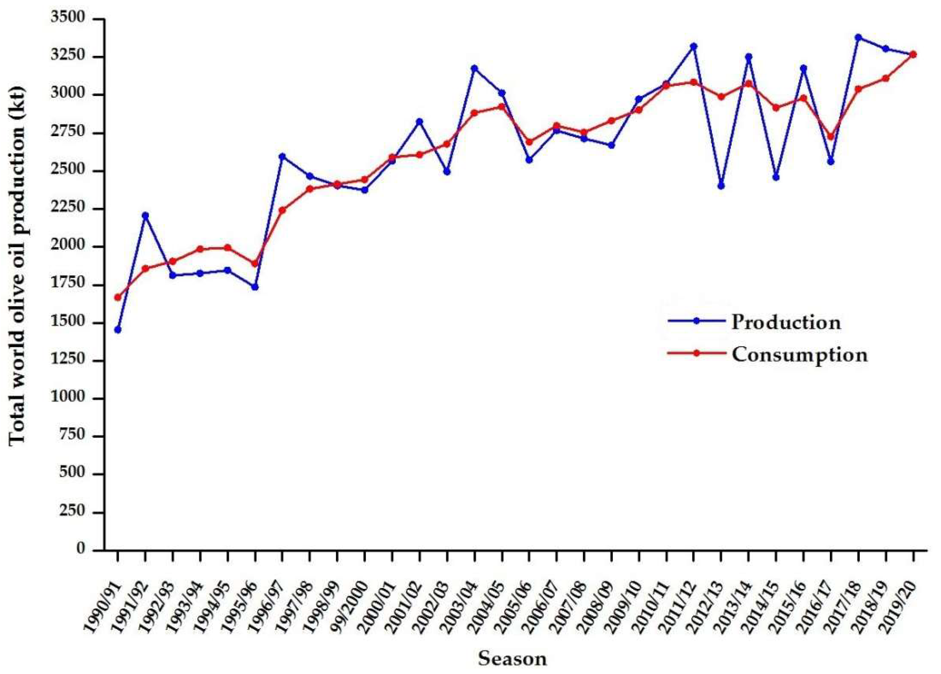
:1. Introduction
2. Materials and Methods
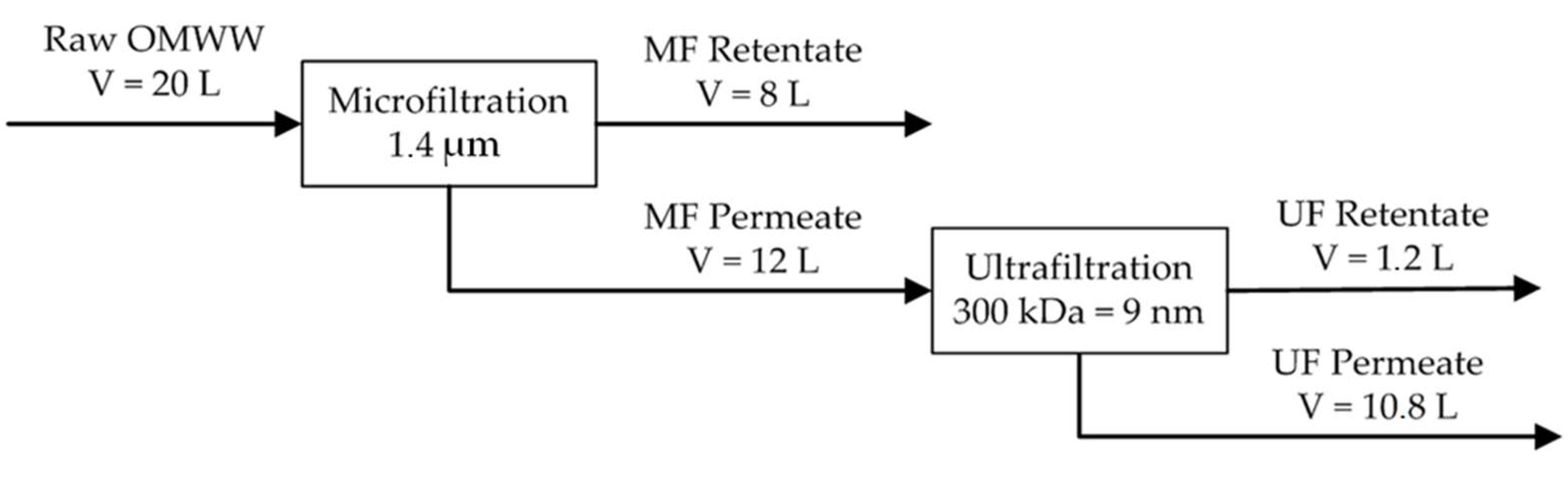
2.1. Experimental
2.2. Conversion Reactions
2.2.1. Thermal Cracking
2.2.2. Steam Reforming
2.2.3. Methanation
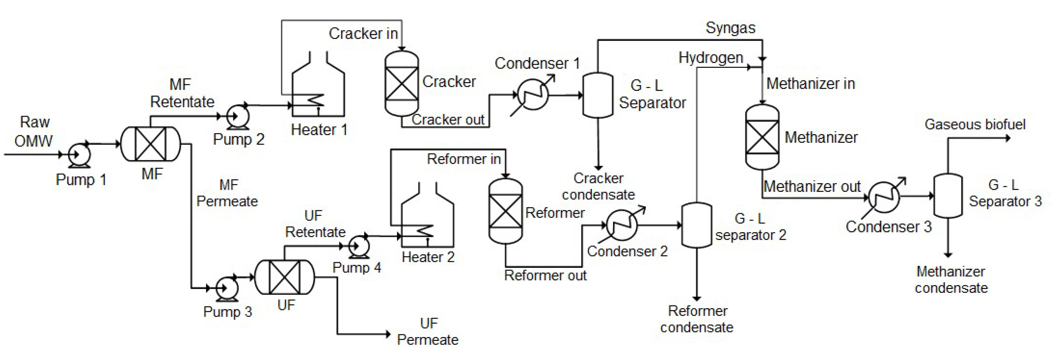
2.3. Conversion Process
3. Results
3.1. Process Simulation
3.1.1. Design Basis
3.1.2. Simulation Software and Assumptions
- gaseous phase: hydrogen, carbon monoxide, carbon dioxide, water, light hydrocarbons up to C4;
- liquid phase: toluene, benzene, and water;
- solid phase: graphitic carbon.
- adiabatic reactors were assumed for all the conversion steps;
- the reactors were modeled based on free Gibbs energy minimization criterion to reach chemical and phase equilibrium conditions, based on the knowledge of the following information: operating pressure; operating temperature, or thermic power exchanged, and chemical compounds present in the outlet stream;
- Furnaces Heater 1 and Heater 2 supply to the feed both the heat to reach the reaction temperature and that required by the endothermic cracking and reforming reactions; it is assumed the reaction to take place inside the furnace, but two distinct units were needed for simulation purpose;
- the exothermic methanation reaction was assumed as isothermal; accordingly, the equipment should be provided with a proper cooling system (jacket, coils, or external recirculation) to remove the reaction heat;
- membrane separation units were simulated based on the cut-off mass balances resulting from the experiments;
- volumetric lobular type (Pumps 1 and 2) and gear type (Pumps 3 and 4) pumps were selected, due to the low flow rate and high viscosity of the liquids streams.
3.2. Results of the Simulation
3.2.1. Thermal Cracking Section
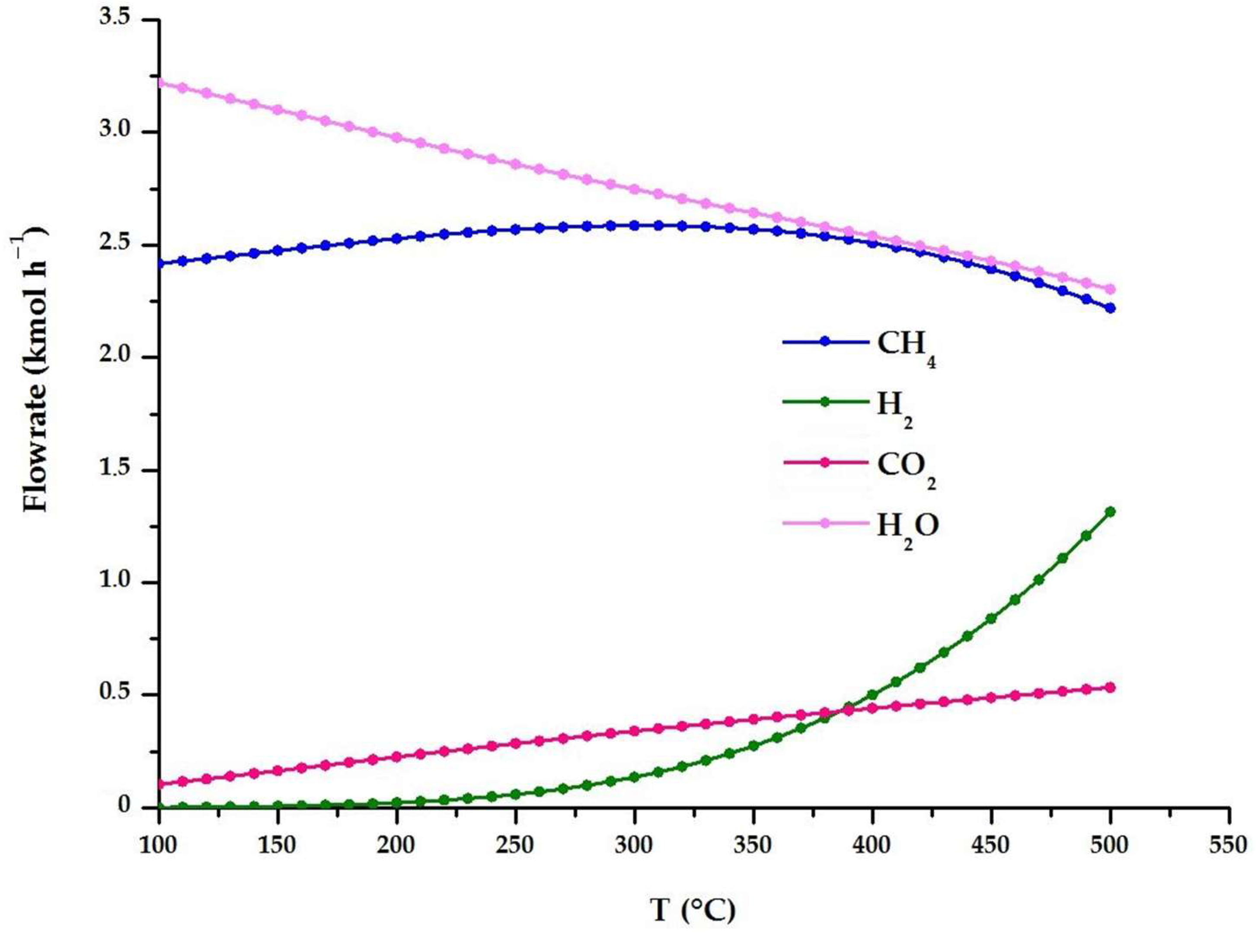
3.2.2. Steam Reforming Section
3.2.3. Methanation Section
4. Discussion
4.1. Alternative Process Options
4.2. Biofuel Composition
4.3. Heat Balance
5. Conclusions
Author Contributions
Funding
Acknowledgments
Conflicts of Interest
References
- International Olive Oil Council (IOOC). Available online: https://www.internationaloliveoil.org/wp-content/uploads/2020/12/HO-W901–17–12–2021-C.pdf (accessed on 17 January 2022).
- International Olive Oil Council (IOOC). Available online: https://www.internationaloliveoil.org/wp-content/uploads/2020/12/HO-W901–17–12–2021-P.pdf (accessed on 17 January 2022).
- The EU Olive and Olive Oil Sector—Main Features, Challenges and Prospects, Briefing, September 2017. Available online: https://www.europarl.europa.eu/thinktank/en/document/EPRS_BRI(2017)608690 (accessed on 17 January 2022).
- Morillo, J.A.; Antizar-Ladislao, B.; Monteoliva-Sánchez, M.; Ramos-Cormenzana, A.; Russell, N.J. Bioremediation and biovalorization of olive-mill wastes. Appl. Microb. Biotech. 2009, 82, 25–39. [Google Scholar] [CrossRef] [PubMed]
- Tsagaraki, E.; Lazarides, H.N.; Petrotos, K.B. Olive mill wastewater treatment. In Utilization of By-Products and Treatment of Waste in Food Industry; Oreopoulou, V., Winfried, R., Eds.; Springer Science + Business Media: New York, NY, USA, 2007; pp. 133–157. [Google Scholar]
- Amaral, C.; Lucas, M.S.; Coutinho, J.; Crespi, A.L.; Anjos, M.D.R.; Pais, C. Microbiological and physicochemical characterization of olive mill wastewaters from a continuous olive mill in Northeastern Portugal. Bioresour. Technol. 2008, 99, 7215–7223. [Google Scholar] [CrossRef] [PubMed]
- Coz, A.; Villegas, M.; Andre, A.; Viguri, J.R.; Mantzavinos, D.; Xekoukoulotakis, N.P. Management scenarios for olive oil mill waste based on characterization and leaching tests. J. Chem. Technol. Biotechnol. 2011, 86, 1542–1547. [Google Scholar] [CrossRef]
- De Marco, E.; Savarese, M.; Paduano, A.; Sacchi, R. Analytical, nutritional and clinical methods e characterization and fractionation of phenolic compounds extracted from olive oil mill wastewaters. Food Chem. 2007, 104, 858–867. [Google Scholar] [CrossRef]
- Davies, L.C.; Vilhena, A.M.; Novais, J.M.; Martins-Dias, M. Olive mill wastewater characteristics: Modeling and statistical analysis. Grasas Aceites 2004, 66, 233–241. [Google Scholar] [CrossRef]
- Sierra, J.; Marti, E.; Garau, M.; Cruanas, R. Effect of the agronomic use of olive oil wastewater: Field experiments. Sci. Total Environ. 2007, 378, 90–94. [Google Scholar] [CrossRef]
- Fiorentino, A.; Gentili, A.; Isidori, M.; Monaco, P.; Nardelli, A.; Parrella, A. Environmental effects caused by olive mill wastewaters: Toxicity comparison of low-molecular-weight phenol components. J. Agric. Food Chem. 2003, 51, 1005–1009. [Google Scholar] [CrossRef]
- Koutsos, T.M.; Chatzistathis, T.; Balampekou, R.L. A new framework proposal, toward a common EU agricultural policy, with the best sustainable practice for the re-use of olive mill wastewater. Sci. Total Environ. 2017, 622–623, 942–953. [Google Scholar] [CrossRef]
- Ochando-Pulido, J.M.; Pimentel-Moral, S.; Verardo, V.; Martinez-Ferez, A. A focus on advanced physico-chemical processes for olive mill wastewater treatment. Sep. Purif. Technol. 2017, 19, 161–174. [Google Scholar] [CrossRef]
- Gebreyohannes, A.Y.; Mazzei, R.; Giorno, L. Trends and current practices of olive mill wastewater treatment: Application of integrated membrane processes and its future perspectives. Sep. Purif. Technol. 2016, 162, 45–60. [Google Scholar] [CrossRef]
- Russo, C. A new membrane process for the selective fractionation and total recovery of polyphenols, water and organic substances from vegetation waters (VW). J. Membr. Sci. 2007, 288, 239–246. [Google Scholar] [CrossRef]
- Cassano, A.; Conidi, C.; Giorno, L.; Drioli, E. Fractionation of olive mill wastewaters by membrane separation techniques. J. Hazard. Mater. 2013, 248–249, 185–193. [Google Scholar] [CrossRef] [PubMed]
- Roig, A.; Cayulea, M.L.; Sánchez-Monedero, M.A. An overview on olive mill wastes and their valorization methods. Waste Manag. 2006, 26, 960–969. [Google Scholar] [CrossRef] [PubMed]
- Stoller, M.; Azizova, G.; Mammadova, A.; Vilardi, G.; Di Palma, L.; Chianese, A. Treatment of olive oil processing wastewater by ultrafitration, nanofiltration reverse osmosis and biofiltration. Chem. Eng. Trans. 2016, 47, 409–414. [Google Scholar]
- Casanovas, A.; Galvis, A.; Llorca, J. Catalytic steam reforming of olive mill wastewater for hydrogen production. Int. J. Hydrogen Energy 2015, 40, 7539–7545. [Google Scholar] [CrossRef] [Green Version]
- Tosti, S.; Accetta, C.; Fabbricino, M.; Sansovini, M.; Pontoni, L. Reforming of olive mill wastewater through a Pd-membrane reactor. Int. J. Hydrogen Energy 2013, 38, 10252–10259. [Google Scholar] [CrossRef]
- Tosti, S.; Sansovini, M. A process for treating waste waters of oil mills by means of reforming reactions, and plant therefor. European Patent No. 13829002.8, 15 February 2017. [Google Scholar]
- Tosti, S.; Cavezza, C.; Fabbricino, M.; Pontoni, L.; Palma, V.; Ruocco, C. Production of hydrogen in a Pd-membrane reactor via catalytic reforming of olive mill wastewater. Chem. Eng. J. 2015, 275, 366–373. [Google Scholar] [CrossRef]
- Tosti, S.; Fabbricino, M.; Pontoni, L.; Palma, V.; Ruocco, C. Catalytic reforming of olive mill wastewater and methane in a Pd-membrane reactor. Int. J. Hydrogen Energy 2016, 41, 5465–5474. [Google Scholar] [CrossRef]
- Alique, D.; Bruni, G.; Sanz, R.; Calles, J.A.; Tosti, S. Ultra-Pure Hydrogen via Co-Valorization of Olive Mill Wastewater and Bioethanol in Pd-Membrane Reactors. Processes 2020, 8, 219. [Google Scholar] [CrossRef] [Green Version]
- Messineo, A.; Picciotto Maniscalco, M.; Volpe, R. Biomethane recovery from olive mill residues through anaerobic digestion: A review of the state of the art technology. Sci. Total Environ. 2020, 703, 135508. [Google Scholar] [CrossRef]
- Della Toffola. Available online: www.dellatoffola.it (accessed on 26 January 2022).
- Crialesi, A. Trattamento delle Acque di Vegetazione dei Frantoi Oleari Mediante un Processo di Separazione a Membrane e Reforming. Master’s Thesis, “Sapienza” University of Rome, Rome, Italy, 20 January 2021. [Google Scholar]
- Singleton, V.L.; Orthofer, R.; Lamuela-Raventós, R.M. Analysis of total phenols and other oxidation substrates and antioxidants by means of Folin-Ciocalteu reagent. Methods Enzymol. 1999, 299, 152–178. [Google Scholar]
- Rocha, C.; Soria Luís, M.A.; Madeira, M. Screening of commercial catalysts for steam reforming of olive mill wastewater. Renew. Energy 2021, 169, 765–779. [Google Scholar] [CrossRef]
- Rocha, C.; Soria Luís, M.A.; Madeira, M. Use of Ni-containing catalysts for synthetic olive mill wastewater steam reforming. Renew. Energy 2022, 185, 1329–1342. [Google Scholar] [CrossRef]
- Paraskeva, P.; Diamadopoulos, E. Technologies for olive mill wastewater (OMW) treatment: A Review. J. Technol. Biotechnol. 2006, 81, 1475–1485. [Google Scholar] [CrossRef]
- Idem, R.O.; Katikaneni, S.P.R.; Bakhshi, N.N. Thermal cracking of Canola oil: Reaction products in the presence and absence of steam. Energy Fuel 1996, 10, 1150–1162. [Google Scholar] [CrossRef]
- Goula, A.M.; Adamopoulos, K.G. A Method for Preparing a Novel Solid Product from Olive Mill Wastewater: Wastewater Characterization and Product Recovery, Drying Technology. Dry Technol. 2013, 31, 339–349. [Google Scholar] [CrossRef]
- International Olive Oil Council (IOOC). Olive Oil Quality Improvement; International Olive Oil Council: Madrid, Spain, 1990. [Google Scholar]


| Characteristics of the Membranes | Value |
|---|---|
| Number of channels | 7 |
| Diameter of each channel | 2 mm |
| Length of each module | 0.25 m |
| Permeable surface | 0.034 m2 |
| Trans-membrane pressure | 1.5 bar (MF)/2 bar (UF) |
| Tangential flux velocity | 2.5 m s−1 (UF)/3 m s−1 (MF) |
| Permeate flux | 60 L h−1 m−2 (UF)/90 L h−1 m−2 (MF) |
| Sample | TOC (g L−1) | TOCSt. Dev. (g L−1) | COD (gO2 L−1) | Total Solids (mL L−1) | Total Polyphenols [28] 1 (gGAE L−1) |
|---|---|---|---|---|---|
| Raw OMW | 12.46 | ±0.58 | 91.70 | 100 | 0.39 |
| MF Retentate | 22.77 | ±1.41 | 77.75 | 150 | 0.04 |
| MF Permeate | 3.57 | ±1.12 | 32.67 | <10 | 0.25 |
| UF Retentate | 10.35 | ±0.49 | 29.75 | 10 | 0.45 |
| UF Permeate | 2.33 | ±0.07 | 34.25 | <10 | 0.12 |
| Stream | Flow Rate (L h−1) | TOC (g L−1) | Oleic Acid Equivalents (g L−1) | Oleic Acid Organic Load (kg h−1) |
|---|---|---|---|---|
| Raw OMW | 5000 | 12.46 | 16.29 | 81.472 |
| MF Retentate | 2000 | 22.77 | 29.78 | 59.544 |
| MF Permeate | 3000 | 3.57 | 4.67 | 14.006 |
| UF Retentate | 300 | 10.35 | 13.54 | 4.061 |
| UF Permeate | 2700 | 2.33 | 3.05 | 8.227 |
| Operating Condition | Cracker | Condenser 1 | G-L Separator 1 |
|---|---|---|---|
| Flow rate (kg h−1) | 2055.7 | 2055.7 | 2055.7 |
| Pressure (bar) | 5.0 | 4.8 | 4.5 |
| Inlet/outlet temperature (°C) | 40.0/355.9 | 355.9/60.0 | 60.0/59.9 |
| Heat supplied (+) or removed (−) (kW) | +1730 | −1591 | - |
| Variable | Syngas Stream | |
|---|---|---|
| Flow rate | (kg h−1) | 102.8 |
| CH4 | (mol.%) | 18.98 |
| H2 | (mol.%) | 57.06 |
| CO2 | (mol.%) | 19.54 |
| CO | (mol.%) | 0.06 |
| H2O | (mol.%) | 4.37 |
| Operating Condition | Reformer | Condenser 2 | G-L Separator 2 |
|---|---|---|---|
| Flow rate (kg h−1) | 303.5 | 303.5 | 303.5 |
| Pressure (bar) | 7.0 | 6.8 | 6.6 |
| Inlet/outlet temperature (°C) | 40.0/702.1 | 702.1/60.0 | 60.0/60.0 |
| Heat supplied (+) or removed (−) (kW) | +324 | −303 | - |
| Variable | Hydrogen Stream | |
|---|---|---|
| Flow rate | (kg h−1) | 7.91 |
| CH4 | (mol.%) | 0.01 |
| H2 | (mol.%) | 81.38 |
| CO2 | (mol.%) | 14.91 |
| CO | (mol.%) | 0.72 |
| H2O | (mol.%) | 2.99 |
| Variable | Methanizer in Stream | |
|---|---|---|
| Flow rate | (kg h−1) | 110.7 |
| CH4 | (mol.%) | 16.99 |
| H2 | (mol.%) | 59.60 |
| CO2 | (mol.%) | 19.05 |
| CO | (mol.%) | 0.13 |
| H2O | (mol.%) | 4.23 |
| Operating Condition | Methanizer | Condenser 3 | G-L Separator 3 |
|---|---|---|---|
| Flow rate (kg h−1) | 110.7 | 110.7 | 110.7 |
| Pressure (bar) | 4.0 | 3.8 | 3.5 |
| Inlet/outlet temperature (°C) | 60.0/300.0 | 300.1/50.0 | 50.0/50.0 |
| Heat supplied (+) or removed (−) (kW) | −41.2 | −49 | - |
| Variable | Biofuel Gas | |
|---|---|---|
| Flow rate | (kg h−1) | 59.7 |
| CH4 | (mol.%) | 81.30 |
| H2 | (mol.%) | 4.34 |
| CO2 | (mol.%) | 10.97 |
| CO | (mol.%) | 0.01 |
| H2O | (mol.%) | 3.38 |
Publisher’s Note: MDPI stays neutral with regard to jurisdictional claims in published maps and institutional affiliations. |
© 2022 by the authors. Licensee MDPI, Basel, Switzerland. This article is an open access article distributed under the terms and conditions of the Creative Commons Attribution (CC BY) license (https://creativecommons.org/licenses/by/4.0/).
Share and Cite
Crialesi, A.; Mazzarotta, B.; Santalucia, M.; Di Caprio, F.; Pozio, A.; Santucci, A.; Farina, L. Exploiting Olive Mill Wastewater via Thermal Conversion of the Organic Matter into Gaseous Biofuel—A Case Study. Energies 2022, 15, 2901. https://0-doi-org.brum.beds.ac.uk/10.3390/en15082901
Crialesi A, Mazzarotta B, Santalucia M, Di Caprio F, Pozio A, Santucci A, Farina L. Exploiting Olive Mill Wastewater via Thermal Conversion of the Organic Matter into Gaseous Biofuel—A Case Study. Energies. 2022; 15(8):2901. https://0-doi-org.brum.beds.ac.uk/10.3390/en15082901
Chicago/Turabian StyleCrialesi, Alfredo, Barbara Mazzarotta, Marco Santalucia, Fabrizio Di Caprio, Alfonso Pozio, Alessia Santucci, and Luca Farina. 2022. "Exploiting Olive Mill Wastewater via Thermal Conversion of the Organic Matter into Gaseous Biofuel—A Case Study" Energies 15, no. 8: 2901. https://0-doi-org.brum.beds.ac.uk/10.3390/en15082901