Article

An Effective DC-Link Voltage Control Strategy for Grid-Connected PMVG-Based Wind Energy Conversion System

by
Thirumoorthy Ramasamy
,
Ameerkhan Abdul Basheer
,
Myung-Hwan Tak
,
Young-Hoon Joo
* and
Seong-Ryong Lee
*
School of IT Information and Control Engineering, Kunsan National University, 588 Daehak-ro, Gunsan-si 54150, Jeonbuk, Korea
*
Authors to whom correspondence should be addressed.
Submission received: 10 March 2022 / Revised: 12 April 2022 / Accepted: 14 April 2022 / Published: 15 April 2022
(This article belongs to the Special Issue Advances in Wind Energy Control)

Abstract

:
This study presents an effective control strategy for regulating the DC-link voltage in a variable-speed direct-driven (DD) wind energy conversion system (WECS) using a permanent magnet vernier generator (PMVG). To do this, at first, the overall system is configured using back-to-back (BTB) voltage source converters, and the whole system’s dynamical equations are modeled and presented. Following that, a non-linear sliding mode control strategy is introduced as the grid-side converter’s DC-link voltage controller to improve the dynamic performance of the PMVG system and achieve the stable power transfer with the grid. To accomplish this, a proportional and integral (PI)-based sliding surface is designed, and a hybrid reaching law is proposed to suppress chattering and deliver a faster response of DC-link voltage with negligible steady-state tracking error. Finally, the effectiveness and superiority of the proposed control strategy are validated through comparisons with existing methods using simulation and experimental results from a 5-kW PMVG system.

Graphical Abstract

1. Introduction

Due to the higher penetration of wind power into the modern electrical network, the direct-drive (DD) permanent magnet synchronous generator (PMSG)-based larger wind turbines (WTs) are mostly preferred despite their bulky size and heavy weight [1]. On this front, the researchers have been testing the permanent magnet vernier generator (PMVG) in WT applications as a possible replacement for the conventional PMSG because of its smaller size, improved power density, high torque at low speed, and reduced moment of inertia [2]. With this advantage on its side, the design of PMVG-based WT system has been presented in [3]. Similarly, in [4], the authors have indicated how PMVGs can be installed for a small-scale passive wind energy conversion system (WECS). Very recently, in [5], a detailed design and performance comparison of the PMVG and conventional PMSG in WT application on a much larger scale of 15-kW has been presented and it has been further verified that the PMVG can be a viable alternative to the PMSG. Furthermore, for applying DD-based PMVG in multi-megawatt WECS, the feasibility study has been made by the authors in [6]. Also, the benefits and challenges of using PMVG for DD offshore wind system has been investigated in [7]. As a result, it is very essential to investigate the new and efficient control methods to improve the dynamic performance of the emerging PMVG-based WECS. One such investigation of developing an efficient control for maximum power efficiency on a PMVG-based WECS has been very recently made by the authors in [8].
In order to effectively control the overall WECS, the power electronic system bridges the control link between the generator and the grid. Among the many power electronic topologies, a back-to-back (BTB) pulse width modulated (PWM) converter interconnected by a common DC-link capacitor can achieve good performance and efficiency [9]. Furthermore, with this BTB PWM converter, the user can control the machine-side converter (MSC) and the grid-side converter (GSC) independently. Because the DC-link plays a vital role in the transfer of produced power from the generator to the grid, any grid-connected WECS requires an effective DC-link voltage controller to prevent frequent DC-link fluctuations caused by rapid changes in wind power, which may eventually result in total system failure [10,11]. On the other hand, the designed DC-link voltage controller must be capable of providing stable operation and reliable dynamic response over the entire operating range in order to achieve a stable and high-quality power transfer to the grid.
To do this, the GSC control structure is designed to control both voltage and current simultaneously. As a result, the GSC controller must provide an effective DC-link voltage control as well as faster grid current regulation [12]. To achieve these objectives, different control approaches such as model predictive control (MPC) [13,14], direct power control [15,16] (DPC), and vector-oriented control [17] (VOC) have been developed. Even though MPC offers better dynamic characteristics, the need for proper knowledge over plant models and high computational complexity has been resulted in limited success over real-time implementations. Following that, DPC has been found as an alternative control to MPC because of its simple structure and low dependency on the parameters. However, due to its variable switching frequency, there are high ripples associated with flux/torque. As a result, VOC has been mostly preferred over the other two methods, due to its reference transformation approach based on d q decoupling in the synchronous reference frame.
Using the VOC approach, a proportional-integral (PI) controller can be easily implemented for DC-link voltage regulation. Moreover, to meet the various constraints such as stability, dynamic performance, and disturbance rejection, different PI control design techniques based on pole-zero cancellation, pole placement, and optimum criteria method have been proposed in [18]. Further to enhance the PI controller performance, PI with feed-forward compensation technique [19], adaptive PI controllers [20], and observer-based feed-forward compensation technique [21] have been proposed over the recent years. Further, in [22], an improved DC-link voltage fast control scheme based on predictive method has been presented for a PWM rectifier-inverter system. However, these methods do not consider the non-linear nature of the DC-link dynamics, which makes their performance unsatisfactory. To deal with the non-linear dynamics of DC-link, various non-linear control techniques such as input–output linearization [23], feedback linearization [24], backstepping control [25], and sliding mode control (SMC) [26] have been proposed. Even though a better dynamic response can be achieved with the above methods, most of them are prone to the parameter uncertainties. As a result of its superior dynamic performance and resistance to parametric changes, SMC has been widely preferred in voltage control of grid-connected converter systems [27].
Following that, an improved DC-link voltage regulation strategy using SMC for grid-connected converters has been recently proposed in [28]. To extend further, a complimentary SMC technique to suppress the uncertainties in DC-link voltage model has been proposed in [29]. However, the discontinuous control variables involved in SMC lead to the chattering phenomenon, which hinders the SMC implementation. As a result, interesting works in [30,31] have introduced the approaches of selecting the higher-order sliding surface and improved reaching law-based methods for the chattering elimination. Particularly, the reaching law-based approach in SMC allows for the use of an adaptive gain rather than a constant gain, which aids in the chattering reduction [32]. Using this approach, it is possible to achieve a higher gain value for a larger error value and a lower gain value for a smaller error value, eventually resulting in a zero gain as the error approaches zero. As a result, the adaptive gain-based reaching law approach of SMC has found greater success in the DC-link voltage control of PMSG-based wind system [33,34]. Very recently, by using the adaptive gain reaching law employed in [35], improvements in the stable maximum power extraction and DC link voltage regulation problems of PMVG-based WECS have been addressed in [36].
Inspired by the above works and based on adaptive gain approach, this study presents an SMC method with a hybrid reaching law for improved dynamic performance in DC-link voltage controller of the PMVG-based WECS. The following are the overall contributions of the presented study:
  • This study focuses on the development of novel control design aspects for the emerging WECS based on the PMVG as compared to the traditional PMSG-based WECS.
  • An efficient DC-link voltage control is proposed based on non-linear SMC strategy in the GSC control of the PMVG-based WECS which presents improved transient performance.
  • The presented PI-based sliding surface with a hybrid reaching law can achieve a reduced level of chattering and a faster convergence rate with a negligible value of steady-state tracking error.
  • Finally, the effectiveness of the proposed control strategy is demonstrated in both simulation and experiment by comparisons with the conventional methods using a 5-kW PMVG model.
In this study, the remaining sections are organized in the following manner. The system configuration and its mathematically modeled equations are presented in Section 2. The detailed design of SMC with a hybrid reaching law is explained and applied to the PMVG system in Section 3. Section 4 presents the simulation and experimental results of the intended study. Finally, the overall study’s findings are concluded in Section 5.

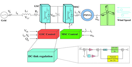
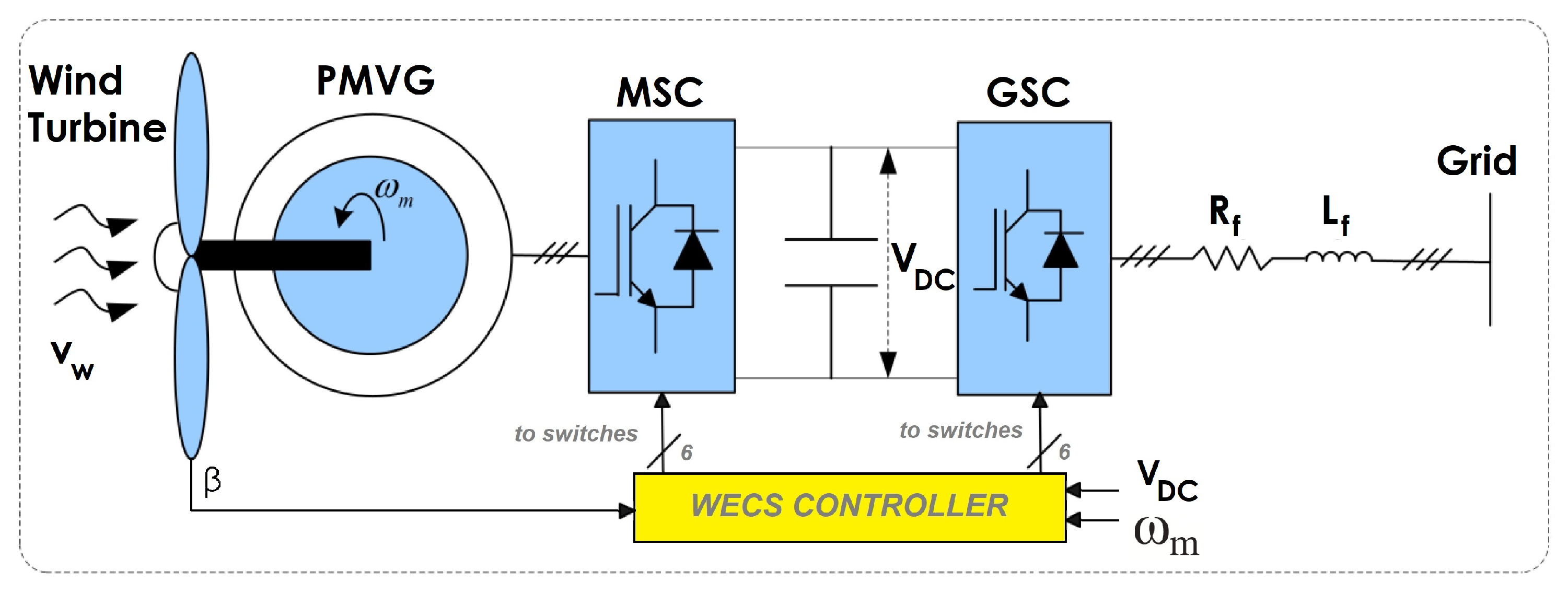
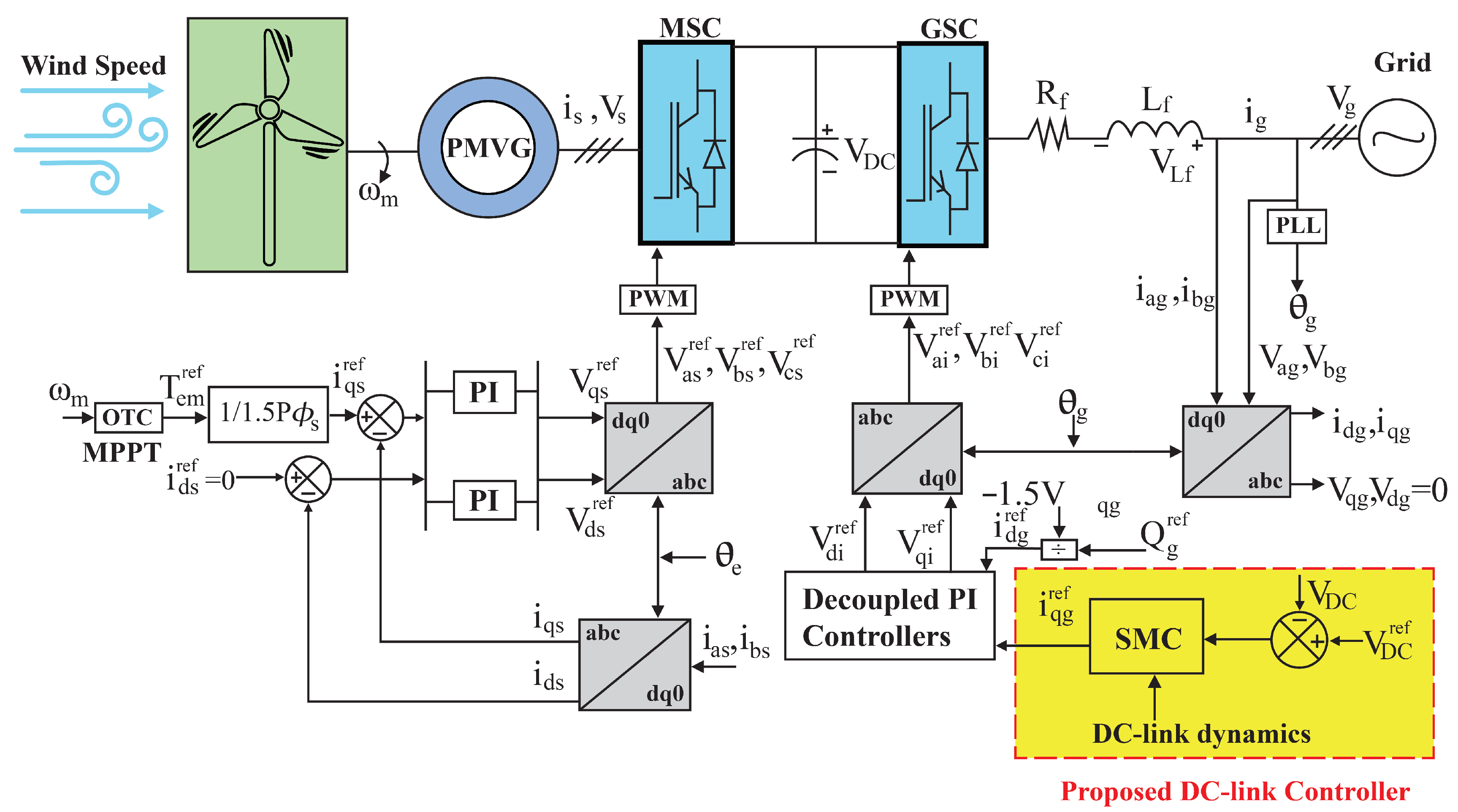
2. System Configuration of PMVG-Based WECS and Its Mathematical Modeling

This section briefly discusses the mathematical modeling of PMVG-based WT with its governing equations. The system configuration of the PMVG-based wind system is shown in Figure 1. From the aerodynamic model of the wind turbine, the developed mechanical torque T m e is given by
T m e = P m ω m = 1 2 ρ π R 3 v w 2 C p ( λ , β ) λ = 1 2 ρ π R 5 ω m 2 C p ( λ , β ) λ 3
where ρ is the air density, R is the rotor blade radius, v w is the wind velocity, ω m is the mechanical rotor speed, and C p is the turbine power coefficient which is a function of blade pitch angle β and tip-speed ratio λ . Next, the dynamical equations of PMVG along with MSC in the synchronous reference frame ( d q ) are stated from [36]:
L d s d i d s d t = R s i d s + ω e L q s i q s + V d s L q s d i q s d t = R s i q s ω e L d s i d s ω e ϕ s + V q s J d ω m d t = T m e T e m B ω m
where J and B are the inertial and frictional coefficients, respectively. L d s , L q s , R s , i d s , i q s , V d s , and V q s are the inductances, resistance, currents, and voltages of the stator-side, respectively. Next, ω e denotes the electrical rotor speed, where ω e = P ω m in which P denotes the generator pole-pairs.
Because the PMVG considered in this study is of surface-mounted, the stator inductances in the perpendicular axes are always equal i.e., L d s = L q s . Furthermore, in order to achieve the optimal operating conditions, the d-axis current is set to zero using the VOC approach from [17], which aligns the q-axis current with the generator torque. As a result, the electromagnetic torque of the PMVG can be finally expressed as:
T e m = 1.5 P ϕ s i q s
where ϕ s denotes the modulation flux linkage, which allows the PMVG to generate a larger back-EMF than the PMSG due to the vernier principle as explained in [2]. From (3), the q-axis stator current ( i q s ) can be used to control the generator torque by employing optimal torque control (OTC) as the maximum power point tracking (MPPT) method. Following that, the dynamical modeling of GSC in the synchronous reference frame can be expressed from [36]:
L f d i d g d t = V d i R f i d g + ω g L f i q g V d g L f d i q g d t = V q i R f i q g ω g L f i d g V q g
where L f , R f , and ω g denote the filter inductance, resistance, and angular velocity of the grid-side. Next, i d g , i q g , V d g , and V q g denote the d q currents and voltages of the grid-side, with V d i and V q i denoting the d q voltages of the inverter. Based on the VOC approach from [17], V d g is made zero and hence, the active power of the system can be obtained as follows:
P g = 3 2 V q g i q g
Finally, the governing equations in order to regulate the DC-link voltage using GSC control can be modeled as
C d V D C d t = i g i s
where i g is the current between the grid and the DC-link, i s is the current between the DC-link and the generator, and C denotes the capacitance of DC-link. Assuming that the inverter is ideal and neglecting the effects of inductor energy as the inductance value is very low for the considered system, the active power on both sides of the inverter can be simplified as follows:
V D C i g = 3 2 V q g i q g
Finally, from (6) and (7), the DC-link voltage dynamics can be obtained as
d V D C d t = 3 V q g 2 C V d c i q g i s C
Using the above modeled equations of the PMVG-based wind system, the overall control structure along with the designed voltage controller in GSC is shown in Figure 2.

3. Design of DC-Link Voltage Control Based on SMC Strategy for PMVG-Based WECS

The operating principle of SMC with its basic structure has been detailed in [37]. From this, it is very clear that the SMC method consists of two basic steps: The first step involves the selection of a proper sliding surface, so that the system state can reach the sliding surface in a finite amount of time. The second step deals with the design of reaching law to ensure faster reaching mode with no chattering. Based on these steps, the design of SMC strategy for the DC-link voltage regulation in PMVG-based WECS has been carried out.

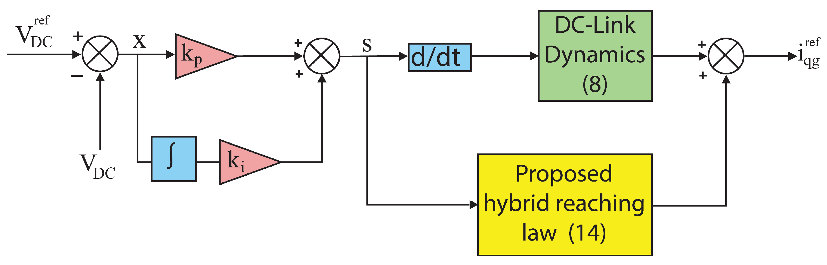
3.1. Sliding Surface Design

The main objective of the design is to achieve a constant DC-link voltage in the PMVG-based WECS that ensure a stable power transfer with the grid. Thus, the tracking error of the DC-link voltage is considered as the state variable, which is given by,
x = V D C r e f V D C
where x is the tracking error of DC-link voltage, V D C r e f is the reference value and V D C is the present value. With these notations, the following sliding surface is designed as a function of proportional and integral of the state variable, given by
s = k p x + k i 0 t x d t
where the gain values of k p and k i are strictly positive which determines the convergence speed of the state variable to the final steady-state reference value ( V D C r e f ) in a finite time. Following that, the key points for selecting the PI-type sliding surface are enlisted below:
1.
Choosing the PI-type sliding equation can help in achieving the properties of both conventional sliding equation and integral-type sliding equation.
2.
By selecting the integral-type sliding equation alone, one can easily eliminate the steady-state error due to its integral action; nevertheless, in the presence of large uncertainties, its response is slow and oscillatory.
3.
Hence, by including the proportional action in the sliding equation, the proposed PI-type sliding equation can ensure the better transient response under the larger uncertainties as well.

3.2. Design of Hybrid Reaching Law (HRL)

This subsection carefully formulates the proposed hybrid reaching law, which ensures reduced chattering levels and faster convergence time. In general, to attain the sliding condition s s ˙ 0 , s ˙ is adopted from the conventional constant gain reaching laws of the following forms [31]:
1 . C o n s t a n t r a t e r e a c h i n g l a w ( C R R L ) s ˙ = α s g n ( s )
2 . C o n s t a n t p r o p o r t i o n a l r a t e r e a c h i n g l a w ( C P R R L ) s ˙ = α s g n ( s ) β s
where α , β > 0 and s g n denotes the signum function. With the selection of proper gain values of α and β , we can guarantee the sliding manifold reaching phase at a constant speed. In CRRL, a higher α value is needed for faster convergence, and as a result of this, it invariably causes an increased chattering level. Next, in CPPRL, due to the additional gain parameter β , it can achieve faster convergence but at the cost of excessive control signal generation when the rate of change of the switching variable is very high. From the above inference, it can be argued that both the reaching laws suffer from the same problem i.e., gain adaptation is not possible depending on the magnitude of sliding surface. Due to this, both of them find limited applications in the SMC design for non-linear dynamical systems.
Hence, an adaptive gain-based reaching law has been explored for robotic applications in the name of exponential reaching law (ERL) in [32], which is given by
s ˙ = α η + ( 1 η ) e δ | s | ψ s g n ( s )
where α , δ , and ψ are positive scalars with 0 < η < 1. This exponential term in the denominator of ERL allows the controller to dynamically adapt the gain value based on the magnitude of | s | . For higher | s | , the gain tends to α / η which is more than α when compared to CRRL and CPPRL. Similarly, when | s | decreases, the exponential term becomes one which allows the gain to switch to α . Even though with gain adaptations, due to the absence of proportional gain term, it has resulted in poor power quality when applied in the PMSG-based WECS [35].
As a result of the above, hybrid reaching law (HRL) can be arrived by inheriting the properties of both CPPRL and ERL along with the inclusion of further improvements. With these added dynamical features, the proposed HRL can achieve better transient performance and reduced chattering levels given as
s ˙ = π ( x , s ) s g n ( s ) β | x | q s π ( x , s ) = α η + 1 + 1 | x | p η e δ | s |
where s and x represent the sliding surface and system state variable with α > 0 , 0 < η < 1, p 1 , δ > 1 , β > 0 and 0 < q < 2.
Here, while considering the first term in (14), when the state variable is far away from the sliding surface, due to higher | s | value, the term e δ | s | will be very small. As a result, the denominator of π ( x , s ) will tends to η , which ultimately converges π ( x , s ) to α / η . If δ is chosen sufficiently larger enough, the state variable can approach the switching surface in a faster manner. On the other hand, when the state variable is close to the switching surface, x and s will become very small, and as a result of this, the denominator term of π ( x , s ) will become larger, which will gradually decrease the reaching rate of the state variable. Finally, when the state variable reaches the sliding surface, π ( x , s ) becomes approximately equal to zero, which will result in reduced system chattering near the sliding surface. Further, with the proportionate term in (14), | x | q makes sure a higher reaching rate at the initial stage is achieved and also helps in the elimination of the steady-state tracking error of DC-link voltage.
Thus, from the above inference, the proposed HRL can achieve the control gain adaptation more elaborately spanning the entire range of sliding surface, irrespective of the error function magnitude.

Reaching Time Calculation

In order to prove that the reaching time of the proposed HRL is faster, the reaching time of CRRL is derived as
t r C R R L = | s ( 0 ) | α
To calculate the reaching time of the proposed HRL in a convenient manner, the reaching law can be rewritten by ignoring the second term as
s ˙ = α η + 1 + 1 | x | p η e δ | s | s g n ( s )
Now, by taking the integration of (16) from 0 to t r H R L , we can obtain the following
s ( 0 ) s ( t r H R L ) 1 s g n ( s ) η + + 1 + 1 | x | p η e δ | s | d s = 0 t r H R L α d t
As s ( t r H R L ) is always going to be zero, we can obtain the reaching time of HRL as follows:
t r H R L = 1 α η | s ( 0 ) | + 1 δ 1 + 1 | x | p η 1 e δ | s ( 0 ) |
Since 1 e δ | s ( 0 ) | < 1 , (18) becomes
t r H R L < 1 α η | s ( 0 ) | + 1 δ 1 + 1 | x | p η
When δ is chosen large enough such that δ 1 + 1 | x | p η , (19) can be expressed as
t r H R L < η | s ( 0 ) | α
Since η < 1 , we can confirm that t r H R L < t r C R R L and a faster dynamic response can be achieved.

3.3. Control Input Design Using the Proposed SMC-HRL

Figure 3 depicts the final control input design for the DC-link voltage regulation using the proposed SMC-HRL. The SMC design goal is to obtain a final control input i q g r e f that can regulate the DC-link at its reference value under various operating conditions. To do that, the time derivatives of (9) and (10) are calculated as follows:
x ˙ = V ˙ D C r e f V ˙ D C s ˙ = k p x ˙ + k i x
Next, from the DC-link dynamics (8) along with the combination of (21), we can arrive at the following expression
s ˙ = k p V ˙ D C r e f k p 3 V q g 2 C V D C i q g r e f + i s C + k i x
Finally, based on (14) and (22), we get the final control input as the following:
i q g r e f = 2 3 C V D C V q g k p k p V ˙ D C r e f + k p i s C + k i x + π ( x , s ) s g n ( s ) + β | x | q s

3.4. Stability Analysis

This subsection presents the stability analysis of the designed DC-link voltage control based on SMC-HRL strategy. To do this, the following Lyapunov function is considered and given by
v = 0.5 s 2
By taking the derivative of (24) with respect to time, it is then expressed as follows:
v ˙ = s s ˙
Using the combination of (22) and (23), the above equation (25) can be further simplified to
v ˙ = s [ π ( x , s ) s g n ( s ) β | x | q s ] = π ( x , s ) | s | β | x | q s 2
where α > 0 ,   β > 0 , 0 < η < 1 due to which V ˙ < 0 can be established. Therefore, from the Lyapunov stability theorem, it is proven that the designed DC-link controller is asymptotically stable which guarantees the system state driven into the sliding surface in finite time.

4. Simulation and Experimental Validation

This section investigates the performance evaluation of the SMC-based DC-link voltage control strategy on a 5-KW PMVG-based WECS [3] in both simulation and experimentation. Table 1 shows the detailed system specifications used in both the simulation and experimental tests. Furthermore, the performance of the proposed SMC-HRL is compared to the conventional PI control, SMC-CPPRL, and SMC-ERL control methods based on constant gain and adaptive gain approaches, demonstrating the significant improvement over these methods.

4.1. Simulation Results

The overall system depicted in Figure 2 is modeled in MATLAB/Simulink with PI-based current control on both MSC and GSC with PI gain values of 5 and 100, respectively. To analyze controller performance in a broad manner, different testing conditions such as system startup period, DC-link reference change, wind speed fluctuations, and grid-side fault are applied and the dynamic responses of all the control methods are observed.

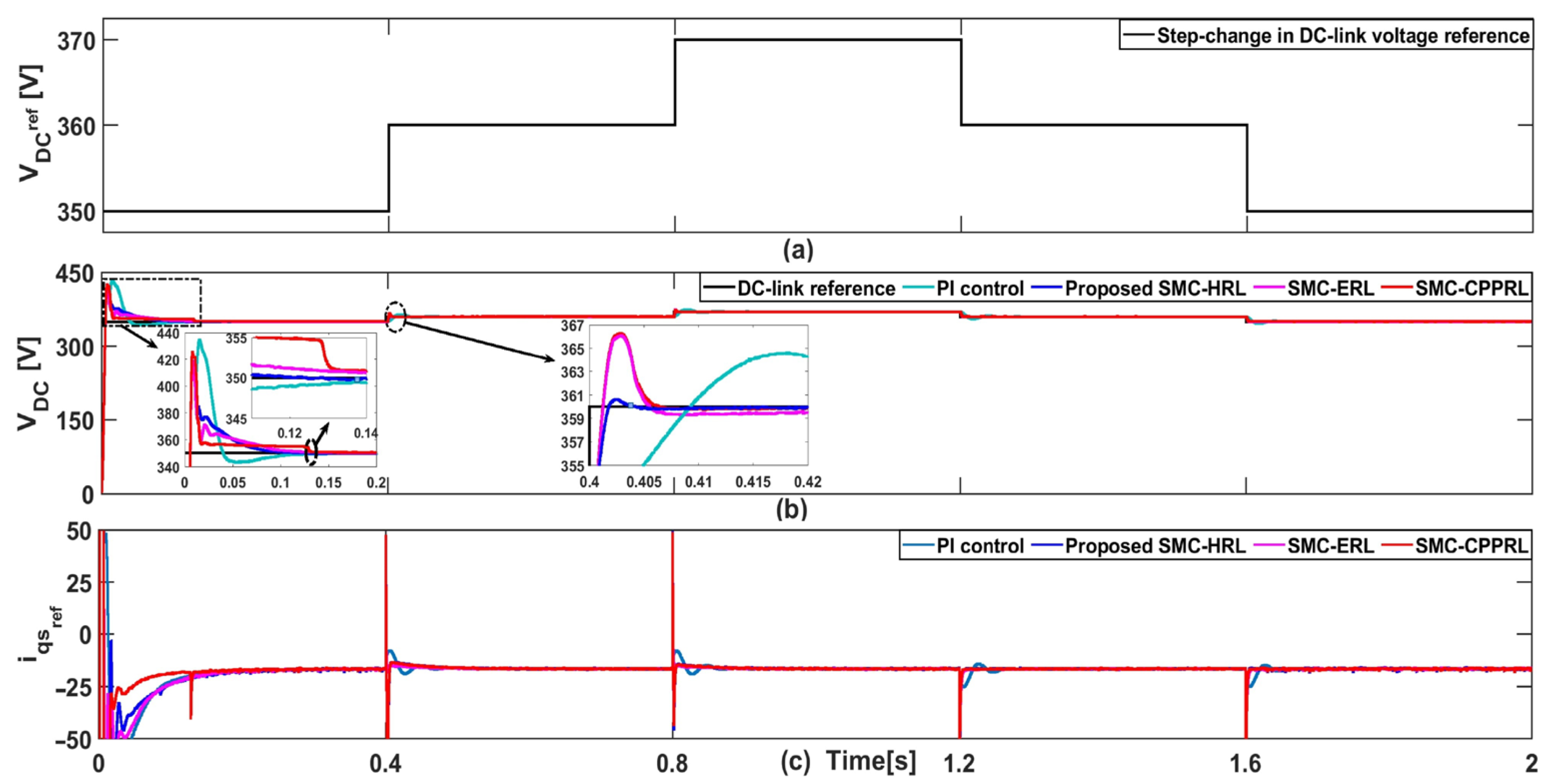
4.1.1. Controller Performance Analysis during the System Startup and DC-Link Reference Change

The simulation responses of all the control methods during the system startup transient period and DC-link reference change are plotted in Figure 4. From this plot, when observing the zoomed part in Figure 4b, we can see the charging instant of DC-link voltage initially from 0 to 350 V during the transient time from 0 s to 0.2 s. After carefully investigating the peak overshoot and settling time of different controllers tested during the system startup, PI control has shown poor dynamic performance with higher overshoot over all other methods. Following that, considering the performance of the various SMC control methods, we can see that SMC-ERL has achieved lower overshoot and faster settling time over SMC-CPPRL, mainly due to its gain adaptation. Finally, by validating the proposed SMC-HRL controller performance over the other methods, we can confirm that the proposed control has achieved an outstanding result in terms of reduced overshoot with very fast convergence towards the reference value. Thus, it is verified that the proposed control has achieved improved dynamic performance during the system startup transient period.
Next, to test the tracking performance of the proposed SMC-HRL over the other control methods, a step-change in DC-link reference voltage is applied and the dynamic responses are plotted in Figure 4. From Figure 4a, it can be observed that a 10 V incremental-change in DC-link reference is applied at an interval of 0.4 s. Accordingly, the tracking performance of all the control methods is observed very closely in the zoomed part of Figure 4b. Based on these observations, it is very clear that though the PI control has achieved lower overshoot than the SMC-CPPRL and SMC-ERL control methods, it has produced a very slow tracking response for all the step-changes applied. After this, the tracking performances of various SMC-based control methods are analyzed in detail. From this analysis, it is evident that both the SMC-ERL and SMC-CPPRL have a similar kind of overshoot in which the SMC-ERL has shown poor steady-state performance due to its higher steady-state tracking error. At this point, it is worth mentioning that the proposed SMC-HRL control is a hybrid mixture of both SMC-CPPRL and SMC-ERL with a few additional developments, it has resulted in better tracking performance with very low overshoot as well as faster settling time with negligible steady-state error. Finally, the control action input i q g r e f of all the control methods are displayed in Figure 4c. From this plot, it is evident that the SMC-CPPRL has produced excessive control signal magnitude to obtain faster convergence, which has been its main limitation as stated earlier. Because of better gain adaptation in the proposed SMC-HRL method, it has resulted in a better regulation over the generation of the control signal magnitude. Hence, based on the overall discussions, we confirmed that the proposed SMC-HRL control has outperformed every other control method.

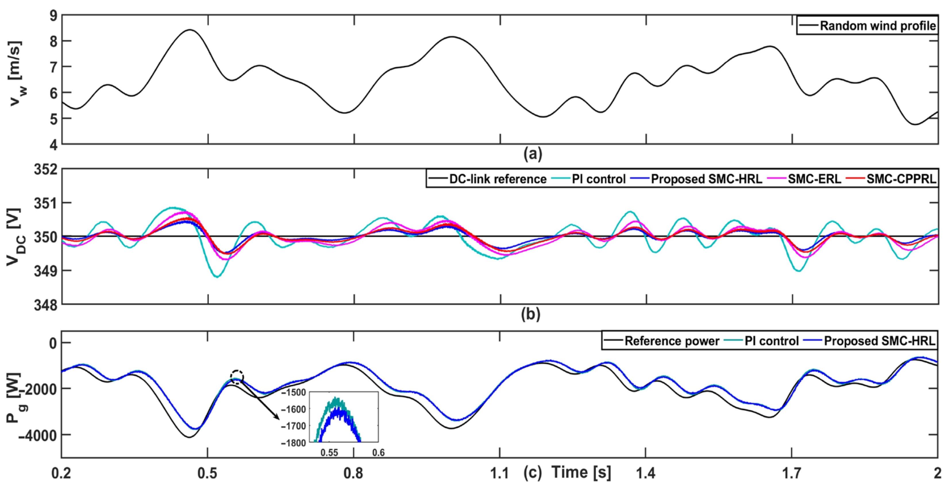
4.1.2. Controller Performance Analysis under the Wind Fluctuations and Grid-Side Fault Conditions

Because wind systems are highly vulnerable to transient disturbances such as frequent wind fluctuations, and intermittent grid-side faults, it may result in the frequent oscillations of the DC-link voltage. As a result, an effective DC-link controller must be designed to ensure a smooth and stable power transfer with the grid. Since the nature of wind is highly unpredictable, we have considered two kinds of wind profile, based on the step-change and the random-change. Thus, by simulating both the wind speed variations along with the grid-side fault scenario for the PMVG-based wind system, the overall responses obtained for all the control methods are depicted in Figure 5 and Figure 6.
For the given step-change wind profile as shown in Figure 5a, all the controller performances are observed and plotted in Figure 5b. As can be seen from Figure 5b, the sudden wind change shifts the generated power which triggers the DC-link oscillation. However, due to the control input action of the individual methods, the overshoot and undershoot in DC-link voltage are arrested, which results in the voltage finally settling at the reference value. From the first zoomed part of Figure 5b, it is evident that the PI control experiences larger overshoot and undershoot with longer settling time as well. Further, when comparing the performance of SMC-based control methods, the proposed SMC-HRL has outperformed both the SMC-ERL and SMC-CPPRL methods in terms of lower overshoot and faster steady-state reaching time as well. As a result of the proposed SMC-HRL control’s improved dynamic performance, more stable active power is delivered with the grid when compared to PI control, as shown in Figure 5c.
Next, to test the controller performance under a grid-side fault, a sudden voltage drop of 30 % from its nominal value is performed at 1 s and restored back at 1.5 s. Due to this fault, unbalanced power flows between the generator and the GSC which has resulted in the rising magnitude of DC-link voltage. As a result, the DC-link voltage begins to fluctuate, as shown in the zoomed portion of Figure 5b. At the same time, each control method produces the required input action to keep the DC-link voltage at its reference value. However, because of its poor dynamic performance, PI control has resulted in an increased overshoot and a very longer settling time. On the other hand, when comparing the performance of SMC-based control methods, the proposed SMC-HRL controller reacts faster, resulting in reduced DC-link voltage overshoot and faster convergence than its peers.
At last, the simulation responses of various control methods under the random wind profile have been plotted in Figure 6. As can be seen from the random wind profile depicted in Figure 6a, it is evident that the DC-link voltage fluctuation is inevitable due to the continuous variations in the wind speed. But, from observing the individual controller performances as shown in Figure 6b, we can see that the PI control has produced poor dynamic performance over the SMC-based methods. However, from the performance comparison of the SMC-based methods, it is evident that the proposed SMC-HRL has produced a faster response, resulting in a much-reduced overshoot and undershoot. Because of the improved dynamic performance of the proposed SMC-HRL, there is a significant improvement in the grid-side active power over the PI control, as can be noticed from the zoomed region of Figure 6c. Based on the above results, we confirmed that the proposed SMC-HRL control has ensured a better DC-link voltage regulation and improved active power delivery to the grid.
Finally, in Table 2, an overall summary of all of these results has been presented and compared with the conventional control methods. From these results, we confirmed that the proposed SMC-HRL control for the DC-link regulation has outperformed the other three methods by achieving lower overshoot and faster convergence time.

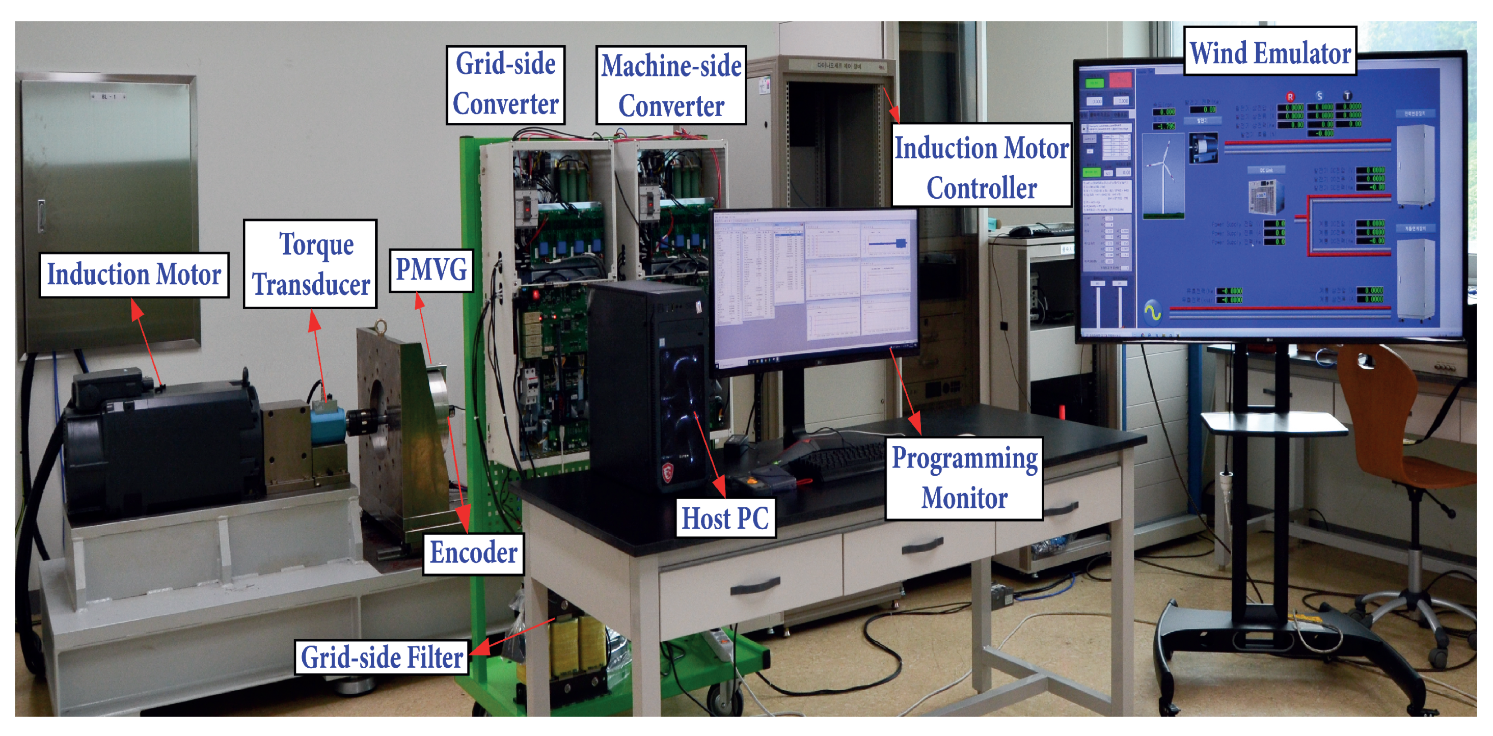
4.2. Experimental Validation and Results

The effectiveness of the proposed DC-link voltage controller is now validated using a grid-connected 5-kW PMVG-based WECS as depicted in Figure 7. The experimental system consists of a wind turbine emulator modeled in LabVIEW that drives an induction motor as the prime mover. Following that, a BTB PWM converter with 1200 V/100 A rated IGBT modules is used to configure the overall system, and using Hall-effect-based sensors, the required voltage and current signals are measured. The DC-link voltage is measured after it has been passed through a low pass filter to remove high-frequency noises. Finally, the MSC and GSC controller algorithms are implemented using TMS320F28335 digital system.
For the experimental validation, three conditions which includes system startup, step-change in DC-link reference, and wind speed variation are considered for testing the controller performances. Accordingly, the output responses under the above testing conditions for the same control methods used in simulation have been obtained as data points and then plotted.

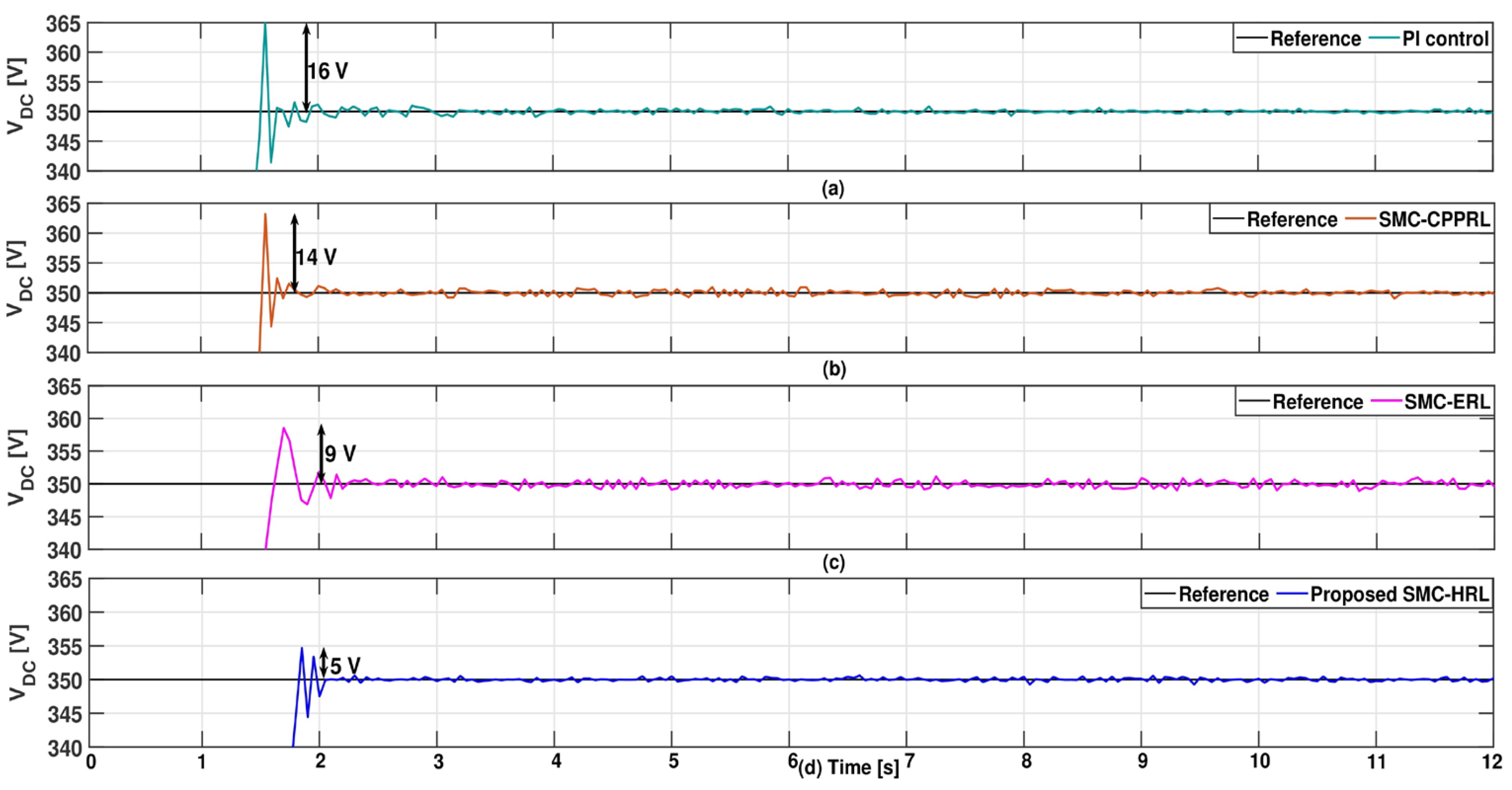
4.2.1. Experimental Verification of Controller Performance during the System Startup Condition

The experimental responses of all the control methods during system startup, when the DC-link voltage is charged from 0 to 350 V, are plotted in Figure 8. From Figure 8a, it is evident that the DC-link response under the PI control has poor dynamic performance with the largest overshoot and very slow convergence time among the different controllers tested. Next, the responses of DC-link voltage for the SMC-based CPPRL and ERL control methods for the same condition are plotted in Figure 8b,c. Both plots show that SMC-ERL outperforms SMC-CPPRL in terms of overshoot, whereas SMC-CPPRL outperforms SMC-ERL in terms of reduced steady-state error. Here, it is attributed to the fact that the SMC-ERL controller’s poor steady-state performance compared to the other SMC-control methods is due to the absence of the necessary proportionate gain term in its reaching condition, which minimizes the steady-state error. Finally, the DC-link voltage response under the proposed controller is plotted in Figure 8d. Because of the added necessary proportional gain term along with its gain adaptation over the entire range of switching function, the proposed SMC-HRL control has been able to generate a response with significantly reduced overshoot, faster convergence speed, and negligible steady-state error. Thus, based on the above discussions on different controller performances, we can easily conclude that the proposed SMC-HRL outperforms all other control methods in terms of superior transient and steady-state performance. Finally, a comparison analysis of all the controller’s performance was presented in Table 3.

4.2.2. Experimental Verification of Controller’s Tracking Performance for the Step-Change in DC-Link Reference

Following that, a step-change in DC-link reference is applied and tested to validate the tracking performance of the proposed controller along with the other control methods. Accordingly, the tracking responses of the DC-link voltage for all the control methods are plotted in Figure 9. The DC-link responses at the time of step-change from 350 V to 360 V in reference have been presented in a zoomed region to analyze the performance of each control method in a detailed manner. At first, by observing the zoomed region in Figure 9a, it is evident that the dynamic performance of PI control is very poor, with higher overshoot and longer settling time towards the reference value. Next, the DC-link responses of SMC-CPPRL and SMC-ERL methods are examined using the zoomed regions in Figure 9b,c. The results of the preceding analysis show that, while SMC-ERL has produced better transient performance than SMC-CPPRL control, it is unable to produce better steady-state performance due to its large steady-state error margin. At last, by looking at the DC-link voltage tracking response in the zoomed region of Figure 9d, the performance of the proposed controller is then analyzed. Based on this analysis, it is very much confirmed that the proposed SMC-HRL control for DC-link regulation has achieved a response with minimum overshoot as well as faster convergence time. As a result, we can conclude that the proposed controller has performed significantly better in terms of tracking the DC-link reference voltage.

4.2.3. Experimental Verification of Controller’s Dynamic Performance for the Wind Speed Variation Condition

Figure 10 depicts the measured experimental responses of DC-link voltage for the wind speed variation condition with step-change profile. We know from the previous testing conditions that the SMC-CPPRL method generates too much magnitude in the control input, whereas the SMC-ERL method always produces a higher steady-state error. As a result, neither of these control methods is taken into account for validation here, and the proposed SMC-HRL control performance is only evaluated by comparing to the PI controller. For the applied step-change wind profile as shown in Figure 10a, the DC-link voltage responses of the PI and proposed control method are measured and plotted in Figure 10b,c, respectively. At every instant of wind speed change, the sudden shift in the generated power has resulted in the fluctuation of DC-link voltage. However, as can be seen from the measured responses of the PI and proposed controller, both control methods exhibit DC-link voltage overshoot as well as undershoot, with the proposed SMC-HRL control outperforming the PI control with less overshoot and undershoot. As a result of the proposed SMC-HRL control’s improved dynamic performance in DC-link regulation, the active power transfer from the GSC to the grid is more smooth and stable as shown in Figure 10d. Finally, Table 4 presents a comparison of the controller’s performance for both the step-change in DC-link reference condition and the wind speed variation condition.
Finally, based on the experimental verification results, we can conclude that the proposed DC-link voltage control based on SMC-HRL strategy ensures a improved dynamic performance of the system in terms of reduced overshoot and faster convergence, allowing the PMVG-based WECS for a smooth and stable power transfer with the grid.

5. Conclusions

An effective DC-link voltage control strategy for the PMVG-based wind energy system based on the non-linear SMC method has been investigated in this study. A detailed design analysis of the proposed DC-link controller, which uses a PI-type sliding surface with a hybrid reaching law, has been presented to demonstrate that it has a faster reaching time than the conventional reaching law methods. Furthermore, the sliding manifold’s stability condition has been derived using the Lyapunov stability theorem which guarantees the asymptotic stability of the closed-loop system. Moreover, the comparative analysis of the proposed SMC-HRL control is carried out with the existing control methods such as PI, SMC-CPRRL, and SMC-ERL based methods. Finally, we have demonstrated that a wide range of testing conditions were used both in simulation and experiment, and the proposed controller has outperformed the above mentioned conventional control methods in terms of improved transient performance with negligible steady-state tracking error as well.

Author Contributions

Conceptualization, T.R.; investigation, T.R.; methodology, T.R. and A.A.B.; validation, T.R.; formal analysis, A.A.B. and M.-H.T.; visualization, T.R. and A.A.B.; writing—original draft preparation, T.R.; writing—review and editing, T.R., Y.-H.J. and S.-R.L.; supervision, Y.-H.J.; project administration, M.-H.T.; funding acquisition, Y.-H.J. and S.-R.L. All authors have read and agreed to the published version of the manuscript.

Funding

This work was partially supported by the Basic Science Research Program through the National Research Foundation of Korea (NRF) funded by the Ministry of Education (NRF- 2016R1A6A1A03013567, NRF-2021R1A2B5B01001484).

Institutional Review Board Statement

Not applicable.

Informed Consent Statement

Not applicable.

Data Availability Statement

Not applicable.

Conflicts of Interest

The authors declare no conflict of interest.

References

  1. Semken, R.S.; Polikarpova, M.; Röyttä, P.; Alexandrova, J.; Pyrhönen, J.; Nerg, J.; Mikkola, A.; Backman, J. Direct-drive permanent magnet generators for high-power wind turbines: Benefits and limiting factors. IET Renew. Power Gener. 2012, 6, 1–8. [Google Scholar] [CrossRef]
  2. Kim, B.; Lipo, T.A. Operation and design principles of a PM vernier motor. In Proceedings of the 2013 IEEE Energy Conversion Congress and Exposition, Denver, CO, USA, 15–19 September 2013; pp. 5034–5041. [Google Scholar]
  3. Kim, B. Design method of a direct-drive permanent magnet vernier generator for a wind turbine system. IEEE Trans. Ind. Appl. 2019, 55, 4665–4675. [Google Scholar] [CrossRef]
  4. Labuschagne, C.; Kamper, M. Permanent magnet Vernier generator design for a small-scale passive wind generator system. In Proceedings of the 2021 IEEE International Electric Machines & Drives Conference (IEMDC), Hartford, CT, USA, 17–20 May 2021; pp. 1–7. [Google Scholar]
  5. Tlali, P.M.; Wang, R.J.; Gerber, S.; Botha, C.D.; Kamper, M.J. Design and performance comparison of vernier and conventional PM synchronous wind generators. IEEE Trans. Ind. Appl. 2020, 56, 2570–2579. [Google Scholar] [CrossRef]
  6. Padinharu, D.K.K.; Li, G.J.; Zhu, Z.Q.; Clark, R.; Thomas, A.S.; Azar, Z. System-Level Investigation of Multi-MW Direct-Drive Wind Power PM Vernier Generators. IEEE Access 2020, 8, 191433–191446. [Google Scholar] [CrossRef]
  7. Padinharu, D.K.K.; Li, G.J.; Zhu, Z.Q.; Clark, R.; Thomas, A.; Azar, Z.; Duke, A. Permanent Magnet Vernier Machines for Direct-Drive Offshore Wind Power: Benefits and Challenges. IEEE Access 2022, 10, 20652–20668. [Google Scholar] [CrossRef]
  8. Mayilsamy, G.; Natesan, B.; Joo, Y.H.; Lee, S.R. Fast Terminal Synergetic Control of PMVG-Based Wind Energy Conversion System for Enhancing the Power Extraction Efficiency. Energies 2022, 15, 2774. [Google Scholar] [CrossRef]
  9. Senthilnathan, K.; Annapoorani, K.I. A review on back-to-back converters in permanent magnet synchronous generator based wind energy conversion system. Indonesian J. Electr. Eng. Comput. Sci. 2016, 2, 583–591. [Google Scholar] [CrossRef] [Green Version]
  10. Yao, J.; Li, H.; Liao, Y.; Chen, Z. An improved control strategy of limiting the DC-link voltage fluctuation for a doubly fed induction wind generator. IEEE Trans. Power Electron. 2008, 23, 1205–1213. [Google Scholar]
  11. Yuan, X.; Wang, F.; Boroyevich, D.; Li, Y.; Burgos, R. DC-link voltage control of a full power converter for wind generator operating in weak-grid systems. IEEE Trans. Power Electron. 2009, 24, 2178–2192. [Google Scholar] [CrossRef]
  12. Wu, Q.; Sun, Y. Modeling and Modern Control of Wind Power; John Wiley & Sons: Hoboken, NJ, USA, 2018. [Google Scholar]
  13. Yaramasu, V.; Wu, B. Model Predictive Control of Wind Energy Conversion Systems; John Wiley & Sons: Hoboken, NJ, USA, 2016. [Google Scholar]
  14. Mohapatra, G.; Debnath, M.K. A Novel Fuzzy-Based Model Predictive Adaptive Controller for a PMSG Wind Turbine. In Innovation in Electrical Power Engineering, Communication, and Computing Technology; Mishra, M., Sharma, R., Kumar Rathore, A., Nayak, J., Naik, B., Eds.; Springer: Singapore, 2022; pp. 65–73. [Google Scholar]
  15. Louar, F.; Ouari, A.; Omeiri, A.; Senani, F.; Rahab, A. Direct power control (DPC) of PMSG based wind energy conversion system. In Proceedings of the 2015 4th International Conference on Electrical Engineering (ICEE), Boumerdes, Algeria, 13–15 December 2015; pp. 1–6. [Google Scholar]
  16. Ayalew, B.E.; Elmoursi, M.S.; El-Saadany, E.F. Enhanced DC Voltage Regulation and Transient Response for Multi-terminal VSC-HVDC System Using Direct Power Control. IEEE Trans. Power Syst. 2021. [Google Scholar] [CrossRef]
  17. Wu, B.; Lang, Y.; Zargari, N.; Kouro, S. Power Conversion and Control of Wind Energy Systems; John Wiley & Sons: Hoboken, NJ, USA, 2011; Volume 76. [Google Scholar]
  18. Bajracharya, C.; Molinas, M.; Suul, J.A.; Undeland, T.M. Understanding of tuning techniques of converter controllers for VSC-HVDC. In Proceedings of the Nordic Workshop on Power and Industrial Electronics (NORPIE/2008), Espoo, Finland, 9–11 June 2008. [Google Scholar]
  19. Luo, A.; Xu, X.; Fang, L.; Fang, H.; Wu, J.; Wu, C. Feedback-feedforward PI-type iterative learning control strategy for hybrid active power filter with injection circuit. IEEE Trans. Ind. Electron. 2010, 57, 3767–3779. [Google Scholar] [CrossRef]
  20. Merai, M.; Naouar, M.W.; Slama-Belkhodja, I. An improved DC-link voltage control strategy for grid connected converters. IEEE Trans. Power Electron. 2017, 33, 3575–3582. [Google Scholar] [CrossRef]
  21. Song, G.; Cao, B.; Chang, L.; Shao, R.; Xu, S. A novel DC-link voltage control for small-scale grid-connected wind energy conversion system. In Proceedings of the 2019 IEEE Applied Power Electronics Conference and Exposition (APEC), Anaheim, CA, USA, 17–21 March 2019; pp. 2461–2466. [Google Scholar] [CrossRef]
  22. Yin, L.; Zhao, Z.; Lu, T.; Yang, S.; Zou, G. An improved DC-link voltage fast control scheme for a PWM rectifier-inverter system. IEEE Trans. Ind. Appl. 2013, 50, 462–473. [Google Scholar] [CrossRef]
  23. Gui, Y.; Li, M.; Lu, J.; Golestan, S.; Guerrero, J.M.; Vasquez, J.C. A voltage modulated DPC approach for three-phase PWM rectifier. IEEE Trans. Ind. Electron. 2018, 65, 7612–7619. [Google Scholar] [CrossRef] [Green Version]
  24. Nguyen, A.T.; Lee, D.C. Advanced LVRT strategy for SCIG-based wind energy conversion systems using feedback linearization and sliding mode control. J. Power Electron. 2021, 21, 1180–1189. [Google Scholar] [CrossRef]
  25. Youness, E.L.; Abdelaziz, E.G.; Aziz, D.; Jamal, B.; Najib, E.O.; Othmane, Z.; Khalid, M.; Bossoufi, B. Implementation and validation of backstepping control for PMSG wind turbine using dSPACE controller board. Energy Rep. 2019, 5, 807–821. [Google Scholar] [CrossRef]
  26. Periyanayagam, A.R.; Joo, Y.H. Integral sliding mode control for increasing maximum power extraction efficiency of variable-speed wind energy system. Int. J. Electr. Power Energy Syst. 2022, 139, 107958. [Google Scholar] [CrossRef]
  27. Zhang, M.; Li, Y.; Liu, F.; Luo, L.; Cao, Y.; Shahidehpour, M. Voltage stability analysis and sliding-mode control method for rectifier in DC systems with constant power loads. IEEE J. Emerg. Select. Top. Power Electron. 2017, 5, 1621–1630. [Google Scholar] [CrossRef]
  28. Gui, Y.; Blaabjerg, F.; Wang, X.; Bendtsen, J.D.; Yang, D.; Stoustrup, J. Improved DC-link voltage regulation strategy for grid-connected converters. IEEE Trans. Ind. Electron. 2020, 68, 4977–4987. [Google Scholar] [CrossRef]
  29. Huang, Y.; Zhang, Z.; Huang, W.; Chen, S. DC-link voltage regulation for wind power system by complementary sliding mode control. IEEE Access 2019, 7, 22773–22780. [Google Scholar] [CrossRef]
  30. Merabet, A.; Ahmed, K.T.; Ibrahim, H.; Beguenane, R. Implementation of sliding mode control system for generator and grid sides control of wind energy conversion system. IEEE Trans. Sustain. Energy 2016, 7, 1327–1335. [Google Scholar] [CrossRef]
  31. Gao, W.; Hung, J.C. Variable structure control of nonlinear systems: A new approach. IEEE Trans. Ind. Electron. 1993, 40, 45–55. [Google Scholar]
  32. Fallaha, C.J.; Saad, M.; Kanaan, H.Y.; Al-Haddad, K. Sliding-mode robot control with exponential reaching law. IEEE Trans. Ind. Electron. 2010, 58, 600–610. [Google Scholar] [CrossRef]
  33. Jeeranantasin, N.; Nungam, S. New sliding mode control of a three-phase AC/DC converter with exponential rate reaching law. In Proceedings of the 2018 International Electrical Engineering Congress (iEECON), Krabi, Thailand, 7–9 March 2018; pp. 1–4. [Google Scholar] [CrossRef]
  34. Huang, J.; Zhang, Z.; Han, J.; Jiang, W. Sliding mode control of permanent magnet generator system based on improved exponential rate reaching law. IET Electr. Power Appl. 2020, 14, 1154–1162. [Google Scholar] [CrossRef]
  35. Mozayan, S.M.; Saad, M.; Vahedi, H.; Fortin-Blanchette, H.; Soltani, M. Sliding mode control of PMSG wind turbine based on enhanced exponential reaching law. IEEE Trans. Ind. Electron. 2016, 63, 6148–6159. [Google Scholar] [CrossRef]
  36. Joo, Y.H.; Antonysamy, R.; Ramasamy, T.; Lee, S.R. Stable maximum power extraction and DC link voltage regulation for PMVG-based WECS. IEEE Trans. Ind. Electron. 2022. [Google Scholar] [CrossRef]
  37. Slotine, J.J.E.; Li, W. Applied Nonlinear Control; Prentice Hall: Englewood Cliffs, NJ, USA, 1991; Volume 199. [Google Scholar]
Figure 1. System configuration of WECS based on PMVG.
Energies 15 02931 g001
Figure 2. Overall control structure of PMVG-based WECS with proposed DC-link controller.
Energies 15 02931 g002
Figure 3. DC-link voltage controller design using the proposed SMC-HRL strategy.
Energies 15 02931 g003
Figure 4. Simulation responses of DC-link voltage for step-change reference value. (a) Step-change in DC-link reference. (b) DC-link voltage. (c) DC-link control input.
Energies 15 02931 g004
Figure 5. Simulation responses of DC-link voltage for step-change wind speed and grid-side fault. (a) Wind speed. (b) DC-link voltage. (c) Grid-side active power.
Energies 15 02931 g005
Figure 6. Simulation responses of DC-link voltage under random wind profile. (a) Wind speed. (b) DC-link voltage. (c) Grid-side active power.
Energies 15 02931 g006
Figure 7. 5-kW PMVG-based experimental system set-up.
Energies 15 02931 g007
Figure 8. DC-link voltage responses in experiment for the system startup condition. (a) PI control. (b) SMC-CPPRL control. (c) SMC-ERL control. (d) Proposed SMC-HRL control.
Energies 15 02931 g008
Figure 9. Experimental tracking responses of DC-link voltage under step-change in DC-link reference condition. (a) PI control. (b) SMC-CPPRL control. (c) SMC-ERL control. (d) Proposed SMC-HRL control.
Energies 15 02931 g009
Figure 10. Experimental responses of DC-link voltage for the wind speed variation condition. (a) Step-change wind profile. (b) PI control. (c) Proposed SMC-HRL control. (d) Grid-side active power.
Energies 15 02931 g010
Table 1. Main parameters of the PMVG-based wind energy system [3].
ParameterValueParameterValue
Rated power5 kWPole-pairs10
Air density1.225 kg/m 3 Stator resistance0.4  Ω
Blade radius2.8 mStator inductance17.5 mH
Optimum TSR 7.1 Flux linkage0.4459 wb
Maximum power coefficient 0.45 Grid-side voltage220 V
Inertia coefficient0.18 kg·m 2 DC-link voltage reference350 V
Viscous coefficient0.0004924 N·m·sDC-link capacitance415  μ F
Cut-in wind speed3 m/sGrid-side frequency60 Hz
Rated wind speed9 m/sGrid-side filter inductance6 mH
Cut-out wind speed15 m/sSwitching frequency10 kHz
Table 2. Comparison analysis of DC-link voltage performance of four control methods from the simulation results.
Test ConditionsControl MethodsOvershoot (%)Convergence Time (s)
System start-upPI24.570.21
SMC-CPPRL21.430.182
SMC-ERL200.16
Proposed SMC-HRL190.13
Step-change in DC-link referencePI1.390.12
SMC-CPPRL1.810.09
SMC-ERL1.670.06
Proposed SMC-HRL0.280.01
Wind variation (step-change profile)PI20.19
SMC-CPPRL1.710.15
SMC-ERL1.140.12
Proposed SMC-HRL0.860.09
Grid-side faultPI1.00.31
SMC-CPPRL0.570.26
SMC-ERL0.710.22
Proposed SMC-HRL0.430.18
Table 3. Comparison analysis of DC-link voltage performance during the system startup condition from the experimental results.
Control MethodsOvershoot (%)Convergence Time (s)
PI4.571.7
SMC-CPPRL40.8
SMC-ERL2.570.75
Proposed SMC-HRL1.430.3
Table 4. Proposed SMC-HRL controller performance compared with other control methods for the step-change in DC-link reference and wind speed variation based on the experimental results.
Control MethodsTest ConditionOvershoot (%)Test ConditionUndershoot (%)
PI 2.5 2.29
SMC-CPPRLStep-change in1.94Wind speed-
SMC-ERLDC-link reference1.11variation-
Proposed SMC-HRL 0.69 1.43
Publisher’s Note: MDPI stays neutral with regard to jurisdictional claims in published maps and institutional affiliations.

