Article

Study on the Effect of Spoiler Columns on the Heat Dissipation Performance of S-Type Runner Water-Cooling Plates

1
College of Mechanical and Electrical Engineering, Shihezi University, Shihezi 832002, China
2
Xinjiang Gold Wind Science & Technology Co., Ltd., Urumqi 830000, China
*
Author to whom correspondence should be addressed.
Submission received: 1 February 2022 / Revised: 12 March 2022 / Accepted: 20 April 2022 / Published: 22 April 2022
(This article belongs to the Topic District Heating and Cooling Systems)

Abstract

:
To solve the problem of low heat dissipation efficiency for the conventional S-type runner water-cooling plate of the fan converter IGBT module, two new water-cooling plates were designed with rectangular and elliptical column structures in the S-shaped runner of the water-cooling plate. The heat dissipation performance, the fluidity of cooling water, and pressure drop of different spoiler column structures were compared using Fluent software for the simulation and experiment. The comparative results show, compared with the water-cooling plate without a spoiler column in the flow channel of the control group, that the spoiler column structure in the flow channel significantly improved the heat dissipation performance of the water-cooling plate. When the inlet velocity of the water-cooling plate was 2 m/s, the highest temperature inside the water-cooling plate with a rectangular spoiler column structure was 12.25 °C, lower than the control water-cooling plate. The highest temperature inside the water-cooled plate with an elliptical structure was 12.40 °C, lower than the control water-cooled plate. The obstructive effect of the elliptical spoiler column structure on water flow was smaller than in the rectangular spoiler column structure. The fluidity of the cooling water inside the elliptical spoiler column structure water-cooling plate was better. When the inlet velocity of the water-cooling plate was 2 m/s, the cooling water flowing through the former was 282 L more than the latter in half an hour. Compared to the pressure drop, we found that in the design group, the pressure drop of the water-cooled plate with a rectangular spoiler column structure was 40,988.3 Pa. The pressure drop of the water-cooled plate with an elliptical spoiler column structure was 25,576.6 Pa. The difference between the two was 15,411.7 Pa, which proves that the energy loss inside the latter is smaller. To further explore the relationship between the heat dissipation and energy consumption of the two types of water-cooled plates, the comprehensive evaluation index η was calculated, ηb = 26.2, ηc = 31.6; therefore, ηb was significantly smaller than ηc. The overall performance of the water-cooled plate with an elliptical spoiler column structure was superior.

1. Introduction

As the power of the fan increases, its loss also increases. Much heat is generated during the working process. Among the many influencing factors, the temperature has the greatest impact on the life of electronic devices. When the ambient temperature exceeds the allowable working temperature, the service life reduces by half for every 10 °C increase [1]. The IGBT (insulated gate bipolar transistor) module is the core component of the wind turbine. The performance of the IGBT module significantly affects the reliability of the wind turbine. Therefore, designing an efficient heat sink for IGBT modules is of great significance in improving the reliability of wind turbines [2,3,4,5].
With the continuous increase in wind turbine power, more efficient liquid cooling technology has become the development direction of IGBT modules. It has always been considered the most efficient heat dissipation method in terms of heat dissipation in high-power converters. The heat dissipation efficiency of liquid cooling is mainly affected by the internal flow channel structure of the water-cooling plate. Scholars have explored the optimal flow channel structure inside the water-cooling plate [6,7,8]. On the other hand, the micro-channel structure based on fins and water-cooled plates that enhance heat transfer also greatly promotes the heat dissipation performance of cold plates [9,10,11,12,13]. Fluidity is also an important indicator for evaluating the performance of water-cooled plates. Fluidity indicates the degree of obstruction in the cooling water of the water-cooled plate during flow [14,15,16,17]. Relevant scholars have studied the heat transfer capacity of the cold plate from different aspects. Based on the field synergy theory, it was proven that the existence of the curvature of the corrugated channel leads to convection chaos in the flow channel and the enhancement of heat transfer. Coolant flow and temperature work together to affect the heat transfer performance of the cold plate. Under low heat flux density, the surface heat transfer coefficient at different positions inside the flow channel is unchanged along the flow direction. Under high heat flux density, the surface heat transfer coefficient at the exit of the runner shows an upward trend [18,19,20].
By aiming at the problem of low heat dissipation efficiency of the existing S-shaped runner water-cooling plate, we designed two new water-cooling plates with rectangular and elliptical spoiler column structures in the S-shaped runner of the water-cooling plate. In this study, we propose a method to increase the disorder degree of cooling water and improve the heat transfer capacity of water-cooled plates by designing rectangular spoiler column structure and elliptical spoiler column structure, respectively, in the S-shaped channel of the water-cooled plate. The obstruction degree of the water-cooling plate with the elliptical spoiler column structure for cooling water is lower than the rectangular spoiler column structure. Our research can guide the further optimization of the water-cooling device of the fan converter. Furthermore, we propose a comprehensive evaluation index η, which is the ratio of the heat dissipation and energy consumption of the water-cooled plate. This indicator can evaluate the comprehensive performance of the water-cooled plate.

2. Structural Design

The external structure of the water-cooled plate is shown in Figure 1. Three IGBT modules are arranged on the upper part of the flow channel of the water-cooling plate. Based on the S-shaped runner, a spoiler column was designed inside the runner of the water-cooled plate to improve its heat transfer capacity. The cooling water flowing through the flow channel is disturbed by the spoiler column arranged in the flow channel, which enhances the turbulent flow effect of the cooling water, increasing the heat transfer coefficient of the water-cooled plate and increasing its heat transfer capacity. There are two cross-sectional shapes of the spoiler column that are rectangular and elliptical. In order to explore the influence of the spoiler column on the heat dissipation performance of the water-cooling plate, a water-cooling plate without an internal spoiler column was set up as a control group for the rectangular spoiler column water-cooling plate, and an elliptical spoiler column water-cooling plate. There were rectangular and elliptical spoiler water-cooling plates in the design group. The internal flow path structures of the three water-cooled plates are shown in Figure 2a–c.

3. Simulation

Two types of S-shaped runner structures with spoiler columns were designed: a rectangular spoiler column runner and an elliptical spoiler column runner. A water-cooled plate without a spoiler column inside the runner was set up as a control group.
In order to investigate their heat dissipation performance, the simulation software Fluent was used to simulate the heat dissipation capability of each water-cooling plate.

3.1. Parameter Setting of the Simulation Process

(1) The heat source selection is an important part of the simulation process. Infineon’s IGBT module model FF1200R17KE_B2 is mostly used in wind farms. The size of the IGBT module in this model was 140 × 130 × 15 mm. The voltage level was 1700 V. The static loss of the IGBT module was 659 W. The dynamic loss was 508 W. The static loss of the diode was 58 W. The dynamic loss of the switch was 226 W. The total loss was 1451 W;
(2) For the structure of the water-cooled plate, a default HD mesh was used in the pre-processing mesh division. The lowest grid quality of the water-cooled plate in Group a was 0.28. The lowest grid quality of the Group b water-cooling plate was 0.28. The lowest grid quality of the water-cooled plate in Group c was 0.26. The simulation results showed that the maximum static temperature of each surface of the three groups of water-cooled plates was almost constant and stable when the calculation grids were 2.01 million, 4.03 million, and 4.25 million, respectively. Therefore, in the final calculation, the grid numbers of the three groups of water-cooled plates obtained the three values above. The water-cooling plate material was aluminum. The ambient temperature was set to 25 °C. The water-cooled plate inlet water temperature was set to 25 °C. The inlet flow rate was 2 m/s, and the number of iterative steps was 400. The zero-equation turbulence model was selected for calculation.

3.2. Mesh Independence Test

In order to improve the computational efficiency and ensure the accuracy of the model, a mesh independence test is needed. When the meshes of a, b, and c water-cooled plates were 2.01 million, 4.03 million, and 4.25 million, respectively, the maximum surface static temperature of the three water-cooled plates remained almost unchanged, as shown in Figure 3. Therefore, the final simulation results are based on the number of meshes at this time.

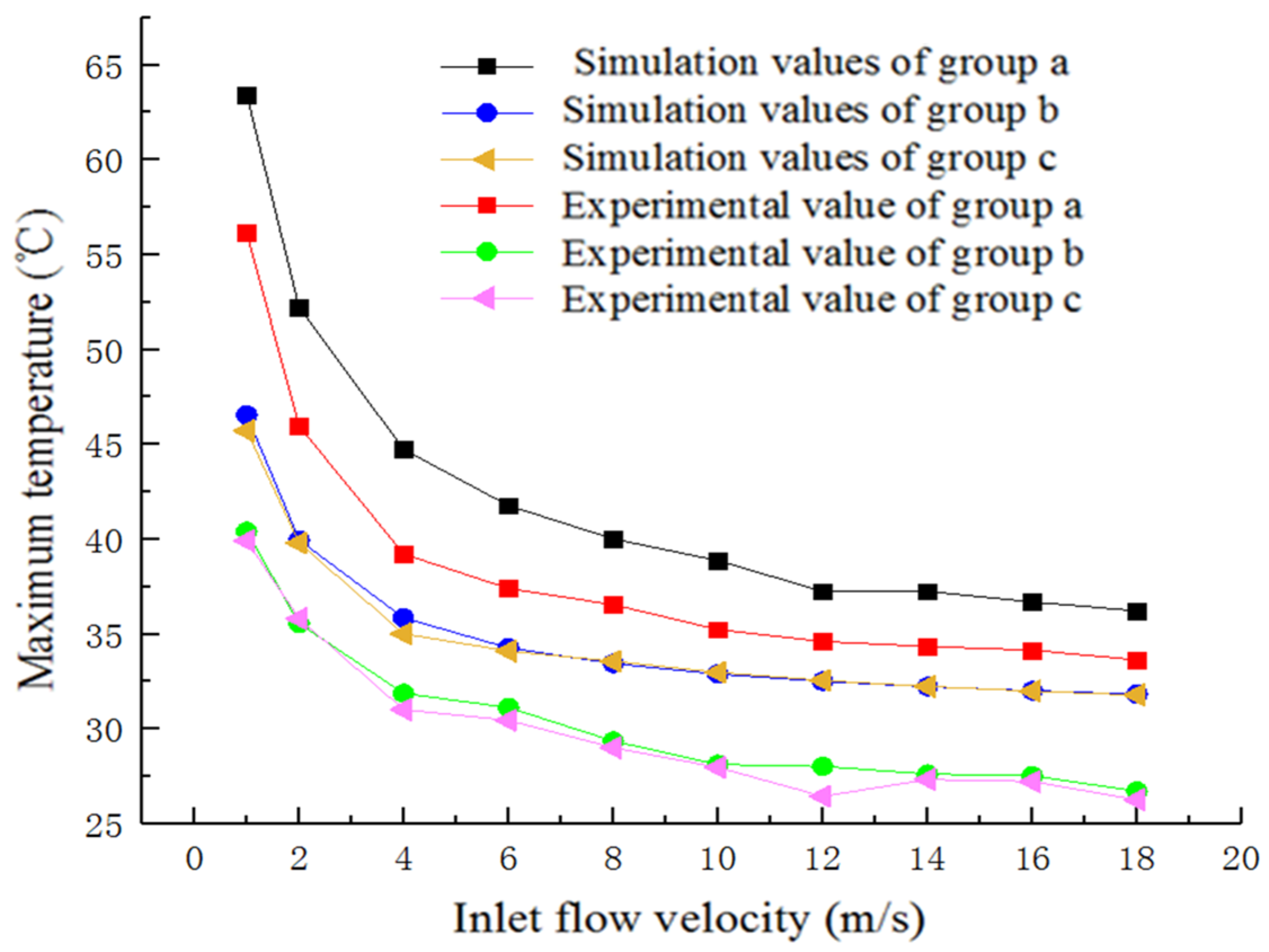
3.3. Analysis of Simulation Results

The simulation results for the three water-cooled plates are shown in Figure 4, Figure 5 and Figure 6:
Temperature:
Figure 4. Comparison between the temperature clouds of three types of water-cooled plates. (a) No Spoiler Column. (b) Rectangular Spoiler Column. (c) Elliptical Spoiler Column.
Energies 15 03085 g004
As shown in Figure 4, The heat dissipation capacity of the two water-cooling plates in the design group is significantly better than in the control group. The maximum temperature of the two water-cooled plates in the design group is 10 °C lower than the control group. The temperature distribution of the water-cooled plate of the design group is also more uniform, and the temperature difference of each part is slight.
Flow Rate:
Figure 5. Comparison between the flow velocity clouds of three types of water-cooled plates. (a) No Spoiler Column. (b) Rectangular Spoiler Column. (c) Elliptical Spoiler Column.
Energies 15 03085 g005
As shown in Figure 5, the maximum flow rate of all three water-cooled plates occurs at the outlet. Compared to the control group, the flow velocity of the two water-cooled plates in the design group reduces by 0.05 m/s and 0.07 m/s, respectively. Although the structure of the spoiler column increases the heat transfer coefficient of the water-cooled plate, it also has a certain obstructive effect on the cooling water, reducing the flow rate. The flow velocity distribution inside the a-type water-cooled plate is more uniform than in the b- and c-type groups. Within the design group, the flow velocity at the edge of the individual runner of the b-type water-cooled plate is higher. The overall flow velocity distribution of the c-type water-cooled plate is more uniform.
Pressure:
Figure 6. Comparison between pressure distribution cloud diagrams of three types of water-cooled plates. (a) No Spoiler Column. (b) Rectangular Spoiler Column. (c) Elliptical Spoiler Column.
Energies 15 03085 g006
As shown in Figure 6, when the inlet flow rate is 2 m/s, the pressure loss of the control water-cooled plate is 8366.6 Pa. The pressure loss of the two water-cooled plates in the design group is significantly higher than the control group due to the spoiler column structures in the two water-cooled plates in the design group. The pressure loss of the b-type rectangular spoiler water-cooled plate is 40,988.3 Pa. The pressure loss of the c-type elliptical spoiler water-cooled plate is 25,576.6 Pa. The pressure loss difference of the latter is less than the former, which proves that there is less internal energy loss for the latter. In comparing this index, the c-type water-cooling plate performed better. The elliptical spoiler column structure effectively reduces the degree of obstruction to the coolant and reduces energy loss.

3.4. Relationship between Cooling Water Inlet Flow Rate and Maximum Static Temperature of Water-Cooled Plate Surface

Ten different inlet flow rate values were set to investigate the relationship between the cooling water inlet flow rate and the maximum static temperature of the water-cooled plate surface. The maximum static temperature of the water-cooled plate surface corresponding to different inlet flow rates was recorded. The results are shown in Table 1.
As shown in Figure 7, the maximum surface static temperature of water-cooled plates of b- and c-types in the design group is significantly lower than water-cooled plates of type a in the control group. By averaging the temperature difference values in the control and design groups at different inlet flow rates, we found that the average temperature difference between the b-type water-cooled plate and a water-cooled plate with different flow rates is 7.69 °C. The average temperature difference between the c-type water-cooled plate and a water-cooled plate with different flow rates is 7.73 °C.

3.5. Relationship between the Inlet Flow Rate and the Maximum Flow Rate Inside the Water-Cooled Plate

In this section, the inlet flow rate was gradually increased from 2 m/s to 18 m/s, and the magnitude of flow loss inside the three water-cooled plates is recorded.The results are shown in Table 2.
As shown in Figure 8, the arrangement of rectangular and elliptical spoiler columns in the flow channel causes some obstruction to the flow of cooling water. Therefore, the maximum internal flow rate of the two water-cooled plates in the design group is lower than the control group. Inside the design group, the cooling water is less obstructed in the streamlined structure of the elliptical spoiler column than in the rectangular spoiler column; therefore, the flow rate inside the water-cooled plate of the elliptical spoiler column structure is higher than in the rectangular spoiler column. The simulation results prove that the streamlined structure of the elliptical spoiler column is more advantageous in terms of the flow of the coolant inside the water-cooled plate. This advantage increases with the increase in the inlet flow rate.

4. Experiment

Based on the previous simulation results, an experiment was set to assess the cooling performance of the three designed water-cooling plates in real operation. In this section, we further investigate the cooling performance of the water-cooling plates by building an experimental platform and designing an experimental process. The experimental platform is shown in Figure 9.

4.1. Fabrication and Selection of Key Components for the Laboratory Bench

The most critical part of this experiment was the water-cooling plate. In order to ensure that the water-cooled plate had good thermal conductivity, aluminum was selected as the material of the water-cooled plate. An even heat plate was installed between the heat source and the water-cooled plate to ensure that the water-cooled plate could evenly absorb the heat generated by the heat source. The even heat plate was fabricated from pure copper. The surfaces of the water-cooled plate and even heat plate were flat and in good contact with each other. In order to further reduce the thermal resistance of the contact between the water-cooled plate and even heat plate, a layer of thermally conductive silicone grease was applied to the surfaces in contact with each other. To prevent heat exchange between the water-cooled plate and the surrounding environment, the surface of the water-cooled plate was covered with foamed silicone. A cast aluminum heating plate was selected as the heat source. During the experiment, the total thermal power of the three IGBT modules was represented by the power of a whole cast aluminum heating plate for ease of arrangement. A hall flow meter was used to measure the flow rate of the cooling water flowing through the water-cooled plate. The static temperature of the water-cooled plate surface was measured with a handheld infrared thermometer.

4.2. Experimental Procedure

During the experiment, the even heat plate was preheated for 5 min, then started to pass water to cool down the temperature. Twelve temperature measurement points were set up on the surface of the water-cooled plate. The temperature change of the measurement points was dynamic when the water passed to cool down. The temperature of each measuring point finally obtained its value in the steady-state. The temperature value of each water-cooled plate at different inlet flow rates was obtained as the average of the steady-state temperatures for 12 temperature measurement points. The statistical analysis results of the data are shown in Table 3. In order to verify the results of the previous simulation and compare the real heat dissipation capacity between the three water-cooled plates, the simulation values of the maximum static temperature and experimental values of the average static temperature of the surfaces for the three water-cooled plates at different inlet flow rates were plotted and analyzed. The results are shown in Figure 10.

4.2.1. The Relationship between Cooling Water Inlet Flow Rate and the Average Static Temperature of the Three Water-Cooled Plates’ Surface

As shown in Figure 10, the overall trend of the experimental numerical results and simulated numerical results are consistent. (1) The thermal performance of the two water-cooling plates in the design group was significantly better than the control group; (2) the heat dissipation capacity of all three water-cooled plates increased as the inlet flow rate increased; (3) within the design group, the heat dissipation capacity of the water-cooling plate with an elliptical spoiler column structure was similar to the water-cooling plate with a rectangular spoiler column structure. The former was slightly stronger than the latter; (4) compared with the simulation value, the overall experimental value was lower. The thermal resistance between the surface of the water-cooling plate and even heat plate and between the even heat plate and heat source surface resulted in the heat of the even heat plate not transferring to the surface of the water-cooled plate quickly. On the other hand, this may have been caused by a part of the heat from the heat source being radiated into the air. Since there is no spoiler column structure inside the water-cooling plate of Group a, its heat dissipation capacity was poor, and there was more remaining heat on the surface of the even heat plate. Due to thermal resistance, there was more heat that could not be quickly transferred to the water-cooling plate. The difference between the simulated and experimental values in Group a is higher than in Groups b or c.

4.2.2. Experimental Research on the Pressure Drop of Three Types of Water-Cooled Plates

Our experiment aimed to explore the pressure loss of three types of water-cooled plates. The greatest pressure loss was at the inlet of the water-cooled plate. There was increasingly less pressure along the path of the fluid flow. In this experiment, by measuring the pressure values at the inlet of the three types of water-cooling plates, the maximum pressure loss values were compared. When the inlet flow rate was 2 m/s, the pressure loss of a type a water-cooled plate was 8366.6 Pa; the pressure loss of a type b water-cooled plate was 40,988.3 Pa, and the pressure loss of a type c elliptical spoiler water-cooled plate was 25,576.6 Pa. The comparison results of the experimental and simulation values were the same. The pressure loss of the two water-cooled plates in the design group was significantly greater than in the control group. Within the design group, the pressure loss of a type b water-cooling plate was greater than a type c water-cooling plate, verifying the simulation results. The overall experiment value was higher than the simulation value due to the external pipeline’s increased resistance loss during the actual experiment process.

4.3. Comparison of the Flow through a Water-Cooled Plate under Different Powers of the Pump

We set this indicator to investigate the obstruction effect of different spoiler column structures on the water flow. However, the actual measurement of the flow rate inside the water-cooled plate is difficult to obtain. By measuring the size of the flow rate through different water-cooled plates while the pump was running at different powers for 30 min, this purpose could also be achieved. The experimental numerical statistics are shown in Figure 11.
As shown in Figure 11, (1) the flow rate of the water-cooled plate in the control group per unit time is significantly greater than the two water-cooled plates in the design group. The turbulent column structure inside the water-cooling plate’s flow channel in the design group had a hindering effect on the cooling water flowing through; (2) within the design group, the flow rate per unit time of the water-cooled plate of the elliptical column structure was significantly higher than the rectangular column structure, proving that the obstruction effect of the elliptical column structure on the water flow was less than the rectangular column structure. As the pump power increased, the flow rate of cooling water through the water-cooled plate increased; this difference also gradually increased. This conclusion is the same as the simulation results in Figure 7.

4.4. Analysis and Calculation of the Relationship between Energy Consumption and Heat Dissipation of the Water-Cooled Plate of the Design Group

In order to create a more comprehensive evaluation of the two water-cooling plates’ performance in the design group, a physical quantity η reflecting the heat dissipation capacity and the energy consumption is introduced in this section. η is the heat dissipation ratio and Q to the power consumption W. The higher the value of η is, the heat decreases with less power consumption, and the overall performance of the water-cooling plate is better.
η = Q W
where Q = P1t; W = Pt; P1 is heating power; and P is water pump power. As shown in Section 3.1, the heating power P1 is 1451 W. When the inlet flow rate is 2 m/s, the pump power corresponding to the type b water-cooling plate is Pb = 42 W, and the pump power corresponding to the type c water-cooling plate is Pc = 35 W. In unit time t, the total calorific value is 1451t, and the total energy consumption is Pt. t refers to the time for the surface temperature of the water-cooling plate to decrease to a stable value. During the actual cooling process, the time for the maximum static temperature of the two water-cooled plates to reach a steady-state value is the same. In order to simplify the calculation, t has the same value of 10 min. When the steady-state is reached, the remaining heat on the water-cooling plate b is Qb = mbcTb, and the remaining heat on the water-cooling plate c is Qc = mccTc. Among them, mb and mc are the masses of the two water-cooled plates, and Tb and Tc are the maximum static temperatures of the surfaces of the two water-cooled plates when the steady-state is reached. The heat dissipation of the two water-cooling plates in this process are: Qbl = 1451tQb = 1451tmbcTb, Qcl = 1451tQc = 1451tmccTc. After measurement, mb = 6.2 kg and mc = 6.1 kg. As shown in the cloud image of the simulation results, Tb = 39.96 °C, Tc = 39.81 °C. The material of the water-cooling plate is aluminum alloy, and its heat capacity is c = 846 J/(kg·°C). Each physical quantity was inserted into the formula to calculate: Qbl = 661,001 J, Qcl = 665,156 J, Wb = 25,200 J, Wc = 21,000 J. These values were inserted into Formula (1), where the η of the two water-cooled plates could be obtained: ηb = 26.2, ηc = 31.6. ηb is significantly smaller than ηc; therefore, the overall performance of the c-type water-cooling plate is superior.

5. Conclusions

Rectangular and elliptical spoiler column structures were designed inside the flow channel of the S-shaped flow channel water-cooling plate. The heat dissipation and cooling water flow performance of three water cooling plates were investigated through simulations and experiments. After proving the advantages of the two water-cooling plates in the design group over the control group and evaluating the comprehensive heat dissipation performance of the two water-cooling plates more comprehensively, the ratio of the energy consumption and heat dissipation of the two water-cooling plates was calculated. Our conclusions include:
(1) The water-cooling plate in the design group shows a significant improvement in cooling capacity compared with the control group. After reaching the steady-state, the maximum static temperature of the surface of the control group was 52.20 °C. The maximum static temperature of the two water-cooled plates b and c in the design group was 39.96 °C and 39.81 °C, respectively. The average temperature difference between the water-cooled plate b and the control group at different flow rates was 7.69 °C. The average temperature difference between the water-cooled plate c and the control group at different flow rates was 7.73 °C, proving that designing a spoiler column inside the flow channel of the water-cooled plate is an effective way to improve the heat transfer capacity of the water-cooled plate. However, the maximum static temperature on the surface of the water-cooled plate decreases with the increase in the inlet flow rate. The increased heat transfer capacity of the water-cooled plates b and c is slightly lower than that of type a;
(2) Within the design group, the flow rate of the type c water-cooling plate per unit time is significantly larger than the type b water-cooling plate. When the inlet velocity of the water-cooling plate was 2 m/s, the cooling water flowing through the former was 282 L more than the latter in half an hour, proving that the obstructive effect of the elliptical spoiler column structure on water flow was less than on the rectangular spoiler column structure. The elliptical spoiler column structure improved the heat exchange capacity of the water-cooled plate while ensuring the fluidity of the cooling water. With the increased pump power, the inlet flow velocity of the water-cooled plate gradually increased from 2 m/s to 18 m/s; this difference also gradually increased, proving that when the flow velocity increases, the advantage of the elliptical spoiler in reducing the obstructed water flow is also more apparent.
(3) By comparing pressure drop, we found that in the design group, the pressure drop of the water-cooled plate of the rectangular spoiler column structure was 40,988.3 Pa, and the pressure drop of the elliptical spoiler column structure water cooling plate was 25,576.6 Pa. The difference between the two was 15,411.7 Pa, proving that the energy loss inside the latter is lower. In order to further explore the relationship between the heat dissipation and energy consumption of the two types of water-cooled plates, the comprehensive evaluation index η can be calculated as: ηb = 26.2, ηc = 31.6. ηb is significantly smaller than ηc. Therefore, the comprehensive performance of the c-type water-cooling plate was better.
(4) Considering the low heat dissipation efficiency of existing water-cooled heat sinks, this paper proposes a method to improve the heat dissipation capacity of water-cooled plates. The heat transfer capacity of the water-cooled plate was improved by designing a rectangular spoiler column structure inside the flow channel. Given the significant energy loss inside the water-cooled plate after the rectangular spoiler structure was designed, the design was further optimized, and an elliptical spoiler structure with better overall performance was designed.

Author Contributions

This study was conceptualized by X.Z. (Xiongfei Zheng) and X.H. The structures were designed by X.Z. (Xiongfei Zheng) and validated by X.H. and L.Z.; X.Z. (Xiongfei Zheng) finished the simulation process. The experimental platform was set up by X.Z. (Xiongfei Zheng) and X.Z. (Xinwang Zhang). The original draft of the manuscript was prepared by X.Z. (Xiongfei Zheng); F.C. and C.M. reviewed and edited the manuscript; X.H. assisted with project administration and L.Z. managed funding acquisition. All authors have read and agreed to the published version of the manuscript.

Funding

This research was funded by the National Natural Science Foundation of China, grant number 51665052, and the development and application of new water-cooled plates for wind turbines, grant number KH0073, and the design and research of wind turbine converter cooling system, grand number CXPY202012.

Conflicts of Interest

The authors declare no conflict of interest.

Nomenclature

ηComprehensive evaluation index, 1
IGBTInsulated gate bipolar transistor
QHeat output, J
WPower consumption, J
Δ P Differential pressure drop between inlet and outlet, Pa
tCooling time, s
mquantity of water-cooling plate, kg
TMaximum static temperature, °C
QlRemaining calories
JcSpecific heat capacity, J (kg·°C)
P1Heating power, W
PPump power, W

References

  1. Li, H.; Hu, Y.; Wang, K.; Quan, R.; Xia, G. Wind power converter IGBT power module dynamic junction temperature calculation and thermal distribution considering the influence of stray inductance. Trans. Chin. Soc. Electr. Eng. 2019, 34, 4242–4250. [Google Scholar]
  2. Reichl, J.; Berning, D.; Hefner, A.; Lai, J.-S. Six-pack IGBT dynamic electro-thermal model: Parameter extraction and validation. In Proceedings of the IEEE Applied Power Electronics Conference & Exposition, Anaheim, CA, USA, 22–26 February 2004. [Google Scholar]
  3. Choi, U.M.; Blaabjerg, F.; Lee, K.B. Study and Handling Methods of Power IGBT Module Failures in Power Electronic Converter Systems. IEEE Trans. Power Electron. 2014, 30, 2517–2533. [Google Scholar]
  4. Liu, S. Design and Simulation of Liquid-Cooled Cold Plate Structure for Megawatt-Class Wind Power Converters. Ph.D. Thesis, Zhejiang Agriculture and Forestry University, Hangzhou, China, 2015. [Google Scholar]
  5. Tang, S. Optimal Design of Cold Plate Structure for Megawatt Wind Power Converter. Ph.D. Thesis, Zhejiang University, Hangzhou, China, 2016. [Google Scholar]
  6. Fu, J.; Xu, X.; Li, R. Battery module thermal management based on liquid cold plate with heat transfer enhanced fin. Int. J. Energy Res. 2019, 43, 4312–4321. [Google Scholar]
  7. Om, N.I.; Zulkifli, R.; Gunnasegaran, P. Influence of the oblique fin arrangement on the fluid flow and thermal performance of liquid cold plate. Case Stud. Therm. Eng. 2018, 12, 717–727. [Google Scholar]
  8. Anbumeenakshi, C.; Thansekhar, M.R. Experimental Investigation of Header Shape and Inlet Configuration on Flow Maldistribution in Microchannel. Exp. Therm. Fluid Sci. 2016, 75, 156–161. [Google Scholar]
  9. Jin, L.; Lee, P.; Kong, X.; Fan, Y.; Chou, S. Ultra-thin minichannel LCP for EV battery thermal management. Appl. Energy 2014, 113, 1786–1794. [Google Scholar]
  10. Cao, J.; He, Y.; Feng, J.; Lin, S.; Ling, Z.; Zhang, Z.; Fang, X. Mini-channel cold plate with nano phase change material emulsion for Li-ion battery under high-rate discharge. Appl. Energy 2020, 279, 115808. [Google Scholar]
  11. Shen, J.; Wang, Y.; Yu, G.; Li, H. Thermal Management of Prismatic Lithium-Ion Battery with Minichannel Cold Plate. J. Energy Eng. 2020, 146, 04019033.1–04019033.11. [Google Scholar]
  12. Li, J.; Xiao, W.; Ge, Y. Research on the shape and arrangement of heat sink fins of liquid-cooled cold plates. Fluid Mach. 2020, 48, 5. [Google Scholar]
  13. Ren, H.; Fang, J.; Zhang, G. Research on Heat Dissipation Characteristics of Microchannel Liquid-cooled Cold Plate. Radar Sci. Technol. 2021, 19, 6. [Google Scholar]
  14. Liu, H.; Li, P.; Van Lew, J.; Juarez-Robles, D. Experimental study of the flow distribution uniformity in flow distributors having novel flow channel bifurcation structures. Exp. Therm. Fluid Sci. 2012, 37, 142–153. [Google Scholar]
  15. Lu, G.; Zhao, J.; Lin, L.; Wang, X. A new scheme for reducing pressure drop and thermal resistance simultaneously in microchannel heat sinks with wavy porous fins. Int. J. Heat Mass Transf. 2017, 111, 1071–1078. [Google Scholar]
  16. Zhao, Z.-N. Study of pressure and flow distribution of collector system-(I) Analytical solution in U-shaped arrangement. J. Sol. Energy 1999, 4, 377–384. [Google Scholar]
  17. Zhao, Z.-N. Study on pressure and flow distribution of collector system(II)-analytical solution in Z-shaped arrangement. J. Sol. Energy 2001, 3, 363–366. [Google Scholar]
  18. Wang, J.; Yan, W.; Li, S. Research on the optimization of the micro-channel structure of the electric vehicle battery cold plate. Automot. Eng. 2020, 42, 9. [Google Scholar]
  19. Yang, G.; Cheng, L.; Wei, Q. Numerical study on the flow and heat transfer characteristics of a series-parallel flow channel cold plate. J. China Acad. Electron. 2021, 16, 7. [Google Scholar]
  20. Hu, L.; Fang, Y.; Yang, W.; Xu, D.; Sun, L.; Li, K. Experimental study on heat transfer characteristics of direct cooling plates in parallel small channels. Acta Refrig. 2021, 42, 6. [Google Scholar]
Figure 1. External structure of water-cooled plate.
Energies 15 03085 g001
Figure 2. The internal structure of three types of water-cooled plates. (a) No spoiler column. (b) Rectangular spoiler. (c) Elliptical spoiler.
Energies 15 03085 g002
Figure 3. Mesh independence test.
Energies 15 03085 g003
Figure 7. Relationship between cooling water inlet flow rate and maximum static temperature of water-cooled plate surface.
Energies 15 03085 g007
Figure 8. The relationship between the maximum flow rate and inlet flow rate of the water-cooled plate with different spoiler column structures.
Energies 15 03085 g008
Figure 9. Picture of the experimental setup.
Energies 15 03085 g009
Figure 10. Comparing the relationship between experimental and simulated values of maximum static temperature and inlet flow velocity for different spoiler column structures.
Energies 15 03085 g010
Figure 11. Water pump at different powers flowing through the three water-cooled plate and the flow rate size relationship.
Energies 15 03085 g011
Table 1. Maximum static temperature values of three water-cooled plate surfaces at different inlet flow rates.
ParametersNumerical Value
Flow Rate (m/s)124681012141618
Group a (°C)63.4252.2144.7441.7840.0238.8837.2637.2636.7036.23
Group b (°C)46.5539.9635.8634.2933.4532.9032.5232.2432.0231.84
Group c (°C)45.7239.8136.0234.4633.5732.9832.5632.2532.0031.80
Table 2. Maximum flow rate values inside the three water-cooled plates at different inlet flow rates.
ParametersNumerical Value
Flow Rate (m/s)124681012141618
Group a (m/s)1.292.585.157.7210.2012.8715.4418.0120.5823.15
Group b (m/s)1.222.444.877.309.7412.1914.6317.0819.5221.96
Group c (m/s)1.252.515.017.5210.0312.5415.0617.5820.1022.62
Table 3. Average static temperature values of three water-cooled plate surfaces at different inlet flow rates.
ParametersNumerical Value
Flow Rate (m/s)124681012141618
Group a (°C)58.1345.9637.2336.4137.5633.2531.1232.2630.1629.65
Group b (°C)40.4235.5631.8831.1329.3628.1428.0327.6327.5427.23
Group c (°C)39.9235.8130.0230.4629.0227.9826.4627.3527.2427.28
Publisher’s Note: MDPI stays neutral with regard to jurisdictional claims in published maps and institutional affiliations.

