
A Review on Crosswind Airborne Wind Energy Systems: Key Factors for a Design Choice


IDMEC, Instituto Superior Técnico, Universidade de Lisboa, Av. Rovisco Pais, 1049-001 Lisboa, Portugal
*
Author to whom correspondence should be addressed.
Energies 2023, 16(1), 351; https://0-doi-org.brum.beds.ac.uk/10.3390/en16010351
Submission received: 30 November 2022
/
Revised: 20 December 2022
/
Accepted: 22 December 2022
/
Published: 28 December 2022
(This article belongs to the Special Issue Airborne Wind Energy Systems)
Abstract
:Airborne wind energy (AWE) has received increasing attention during the last decade, with the goal of achieving electricity generation solutions that may be used as a complement or even an alternative to conventional wind turbines. Despite that several concepts have already been proposed and investigated by several companies and research institutions, no mature technology exists as yet. The mode of energy generation, the type of wing, the take-off and landing approaches, and the control mechanisms, to name a few, may vary among AWE crosswind systems. Given the diversity of possibilities, it is necessary to determine the most relevant factors that drive AWE exploration. This paper presents a review on the characteristics of currently existing AWE technological solutions, focusing on the hardware architecture of crosswind systems, with the purpose of providing the information required to identify and assess key factors to be considered in the choice of such systems. The identified factors are categorized into four distinct classes: technical design factors (aerodynamic performance, mass-to-area ratio, durability, survivability); operational factors (continuity of power production, controllability, take-off and landing feasibility); fabrication and logistical factors (manufacturability, logistics); and social acceptability factors (visual impact, noise impact, ecological impact, safety).
1. Introduction
During the last decades, the global energy consumption has been growing, mainly driven by the growth of the industry sector in several countries in the Middle East, Asia, and Africa [1]. The total energy consumption is expected to keep increasing up to 22% by the end of 2050 [2]. Although this increase embodies a worldwide technological development, it also represents one of the most urgent challenges faced nowadays by humankind. This is mainly due to the fact that, with the current distribution of energy production among the different sources, costs to human health and the environment are becoming unbearable. To date, fossil fuels (coal, natural gas, and oil) account for more than 80% of the global primary energy demand [3], as illustrated in Figure 1.
The combustion of these fuels releases chemical compounds as sulfur and nitrogen oxides, as well as carbon dioxide . On one hand, the first two are major air pollutants that cause adverse human health effects, reduction of agricultural yields, damage to forests and fisheries (acid rain), and damage to buildings and infrastructure. On the other hand, the increase of the concentration in the atmosphere is the main cause of global warming and its ensuing detrimental effects—climate change, biodiversity reduction, and increase of mean sea level, to name a few [4].
In order to address these problems, it is imperative to pursue the usage of a suitable combination of alternative and sustainable energy sources. One of such alternatives is the exploitation of wind energy for electricity production. Nowadays, this resource is mostly explored by using wind turbines (WTs) both on- and offshore. Their main components are the tower (for elevation), the blades (typically three), the nacelle which contains the electric generator, the gearbox, and the control systems. The land occupation of the present wind farms is about 7–8 and 2–3 turbines per , respectively, for onshore and offshore, considering 2–4 , 90–120 diameter turbines. The corresponding power output density is about onshore and offshore, which is 100–300 times lower than that of large thermal plants [5]. Moreover, due to wind intermittency, a wind farm is able to produce an average power that is only a fraction of its rated power (capacity factor). All these issues make current wind energy production not competitive with respect to fossil energies.
According to an assessment carried out by Archer and Caldeira [6], the higher the altitude, the stronger and more consistent the winds are, both on- and offshore. This allows not only increasing rated powers but achieving higher capacity factors as well. For example, in the land mass and coastal areas of Europe at a variable height up to , the wind power density, which is available of the time, doubles when comparing to that at a fixed height of a conventional WT [7]. Marvel et al. [8] showed that the extraction of “only” (i.e., a quantity comparable with the world power demand at today’sdate) of , possible in the whole atmospheric layer, would not produce significant damaging effects at a global scale. Hence, the geophysical potential is huge. Nevertheless, taking advantage of high-altitude wind with the conventional technology would be financially very costly, since higher and structurally more resistant towers would be needed as well as more reliable foundations (the tallest wind turbine is Haliade-X, at [9]). Additionally, only part of the blades contributes efficiently to power production: the outer of the blades account for more than half of the production [10]. Hence, most of the components serve only as structural support.
Thereby, the scenario of finding a technology capable of harvesting the power from winds at higher altitudes than conventional wind turbines ( to ), allowing for larger capacity factors while increasing the productivity of all system constituents, presented itself. Accordingly, the concept of airborne wind energy (AWE) arose, first introduced by [11] in the eighties. Roughly speaking, AWE systems are formed by a flying energy harvesting system, connected to a ground station through a tether, which replaces the conventional WT’s tower and inner part of the blades. This idea represents a substantially smaller material investment per unit of usable power than most other renewable energy sources ( saving as compared to conventional WTs [12]). However, that comes at a cost: while a conventional wind turbine is a stationary construction on the ground, an AWE system operates while flying and, whenever a malfunction occurs, the prospect of a total system destruction comes to light. As a consequence, there are several aspects that must be taken into account in the choice and design of these systems. In addition, despite the high power-to-mass ratio promised by AWE, there is still no mature technology available in the market to enable the large-scale deployment of this technology at comparably low costs. Only in the most recent years have companies such as Kitepower and SkySails commercially deployed systems in the Caribbean [13] and Mauritius islands [14], respectively.
The ultimate goal in this industry is to reach a technically reliable and economically viable technology [15] that can be produced at scale in order to reduce energy costs and help in the present energetic crisis. Accordingly, the most adequate and propitious system for a given site must be identified. Hence, this paper aims to review the scientific advances accomplished all around the world [16] on the most promising AWE systems and, based on this knowledge, identify the key factors determining the choice of a particular system so that an assessment of the design options can be performed.
The review is structured as follows: Section 2 presents a classification of the AWE systems; in Section 3, a description of crosswind systems, addressing their physical foundations and types, is given; in Section 4, the types of wings used in AWE crosswind systems are presented; in Section 5, the relevant characteristics of a system’s tether are mentioned; in Section 6, the take-off/landing subsystems are addressed; Section 7 discusses the integration of these systems in a large-scale scenario; in Section 8, the key factors for a design choice are introduced and discussed; and, finally, Section 9 provides concluding remarks.
2. Types of Airborne Wind Energy Systems
There are several ways to classify AWE systems, e.g., with respect to the means of electricity generation, the flight principles and operation, or the type of flying wing, to name a few. The aim of this section is to present a general description of the existing systems, categorized in such a way that will introduce the upcoming sections. This classification is summarized in Figure 2, where a list of companies/research institutions with accomplished work in prototypes of each category is also provided.
In the first sublevel, these systems are separated according to their in-flight behavior, i.e., if they are subjected to crosswind motion or not. The benefits of flying in crosswind were introduced by Loyd [11]. It basically consists of flying in a transverse direction (or close to it) with respect to the wind flow, which can be implemented through reciprocating patterns, such as figure eights, or returning patterns, such as circles. Usually, the former pattern is preferred since it avoids the twisting of the tether [17]. This kind of motion also allows an increase of the relative velocity of the flying wing. Its principles are presented in Section 3.1.
Crosswind systems are then divided into two groups in line with the location of their electricity generators, which also coincides with the distinction between lift-mode and drag-mode given by Loyd. Power production can be achieved either in a ground station or on-board of the flying wing. The first of these cases is referred to as lift-mode and is analyzed in detail in Section 3.2. One can further split the systems in consonance with the ground station in-operation mobility, i.e., if the station is fixed in one position or moving along a given path while producing power. The second case is designated as drag-mode and is explored in Section 3.3. Here, the flying wing carries on-board generators and sends down the electric current through the tether.
Despite belonging to the same categories, all the systems show certain singularities distinguishing them, such as wing rigidity, flight control, take-off and landing operations, and more.
It is noteworthy that the Alphabet’s subsidiary Makani Power, the main pursuer of on-board generation systems, was shut down in February 2020. The reason given for this outcome was the fact that “the road to commercialization is longer and riskier than hoped”, and that those risks would “outweigh the potential upsides” [18]. In addition, Ampyx Power, explorer of the lift-mode concept, failed to find financial investment and went bankrupt [19]. Even so, these companies contributed strongly to technological developments in AWE, and therefore their ideas and prototypes are also the subject of analysis in the present review.
With respect to noncrosswind systems, a separation of concepts is performed based on the flight operation along with the aircraft configuration. One distinguishes between systems that are fully in rotation (circular flight path) or use rotorcrafts to produce electricity, and systems that use the buoyancy flying principle (meaning that a lighter-than-air gas is utilized). Illustrations of some of these kind of systems, per institution, are showcased in Figure 3. Systems only requiring aerostatic lift are also mentioned, such as the ladder and pumping mill [20]. In addition, it is also possible to establish the distinction between on-ground and on-board generation.
Based on the number of institutions with developed technology in each category, a clear preference for crosswind systems may be identified. In fact, Loyd [11] showed that the power output was larger in these systems due to the increase in relative velocity of the flying wing—see Section 3.1. For these reasons, the analysis conducted in this paper is restricted to AWE crosswind systems only. Moreover, with respect to these, recent studies show that both on-board and on-ground generation systems still have a similar chance of achieving design dominance, with a slight advantage to the latter [26].
3. Principles of AWE Crosswind Systems
3.1. Physical Foundations of Crosswind Motion
In this section, the fundamentals of AWE exploitation using crosswind motion are presented. The potential power that any given wing can extract from a wind field is also established. The following concepts and deductions can be looked up in more detail in [27,28].
As mentioned earlier, it is well known that flying in crosswind with a velocity , in the sense indicated in Figure 4, larger than the true wind speed (assumed to be uniform and constant, parallel to the ground plane), maximizes performance. The wing, as well as the tether, “sees” an airflow with an apparent airspeed, , whose intensity may be substantially larger than . In this way, in comparison with noncrosswind generation, the aerodynamic forces lift (L) and drag (D) are stronger, providing one or two orders of magnitude higher power [11]. These quantities are represented in Figure 4 as resultant forces applied at a single point (pressure center), and are given by Equations (1) and (2), where is the local air density, denotes the wing area, and and stand for the lift and drag coefficients, respectively.
According to Prandtl lifting-line theory [29], the lift coefficient of a finite wing can be obtained from Equation (3), where is the angle of attack, measured between the mean chord of the wing and the velocity vector ; is the zero-lift angle of attack; represents the rate of variation of lift with the angle of attack, in the linear region of a two-dimensional airfoil [29]; and is the aspect ratio of the wing, where b denotes the wingspan.
Regarding the drag coefficient, it is calculated as the sum of both wing and tether drag coefficients. On one hand, the wing drag coefficient () is given as the sum of the profile drag and the induced drag . The former is due to viscous effects and it can be considered constant in the linear region of (before stall occurs); the latter, again in accordance with the lifting-line theory, is obtained from Equation (4), where e stands for the Oswald efficiency.
On the other hand, the tether’s drag coefficient () can be easily calculated if a straight tether of length l, with a cross-section of width w, and a perpendicular drag coefficient are assumed [28]:
Hence, the total drag coefficient of a typical AWE crosswind system is the result of the following summation:
Finally, the total aerodynamic force is given by Equation (7), where denotes an extra drag force coefficient applied by an on-board power generation device (e.g., on-board turbine), if it is the case:
The key point is that the high speed of the wing can be maintained by the wind flow. On one hand, in drag-mode, the on-board turbines are facing the airflow as if they were thrust generators, rotating by action of a drag force, thus producing electrical power. On the other hand, in lift-mode, the high speed leads to the generation of the aerodynamic force (in great part, the lift force) that will traction the tether. The consequent movement can be made useful for harvesting part of the power that the moving wing can potentially extract from the wind field. Furthermore, using crosswind motion also brings an advantage when considering variable wind speed: when the wing is higher, the intensity of the local (and useful) wind speed can be kept constant by reducing the crosswind speed.
Figure 4 sketches an idealized situation where the power extracted from the wind field by the AWE system is maximum. However, in practice, as shown in Figure 5, the AWE system needs an elevation angle to be able to reach some altitude. That makes the crosswind velocity not entirely perpendicular to the wind velocity. Note that, in both cases, the wing is in a completely downwind position. Assuming the tether is completely straight, and hence is in balance with the tether tensile force (as Loyd did [11]), then the real total power that a flying wing can extract from the wind field is given by:
This is called the cosine loss and gives an upper bound on the usable power. Another source of cosine losses is the weight of the airborne system, which leads to the need to impose a larger on the vertical component of in order to compensate the weight. Loyd [11] assumed that both this force and inertia forces were relatively small compared to aerodynamic forces. In fact, for most of the systems flying at strong enough wind speeds, the cosine losses due to gravity can be neglected in power estimations. As detailed in [27], a very small increase of suffices to acquire the mentioned balance of forces. Additionally, numerical simulations presented in [30] showed an increase in power of only when neglecting those forces. Even so, in accurate system modeling studies, these forces must be accounted for.
3.1.1. Power Limit of AWE by Loyd and Diehl
In order to derive a physical upper limit on usable power that any given wing can extract from a wind field, one considers the situation sketched on Figure 5, i.e., . Then, the usable power P is defined as , where comes from Equation (8) and are the power losses. One can argue that, at least, these losses are the ones due to the drag forces of the wing and tether, so as a lower bound, . Thus, by combining all of these considerations, by taking into account Equation (7), and by defining a wing speed ratio , one obtains [27]:
To obtain the upper bound of the available power, one can maximize the right-hand side of Equation (9) over the wing speed ratio. Accordingly, the maximum available power is obtained for a wing speed ratio , resulting in
thus corresponding to an optimal operational wing airspeed, as follows:
This is interpreted as the fundamental upper limit of usable power that can be extracted by any wing flying downwind in any given wind field, irrespective of its direction, and on which any other possible nonaerodynamic forces may act. The limit is both valid for lift-mode and drag-mode, as no such distinction was made in its derivation. One can also determine the tether traction force that maximizes power extraction by substituting in Equation (7) by the optimal operation airspeed, as follows:
Furthermore, the following conclusions can be deduced:
- At optimal operational wing airspeed,meaning that an optimal operated AWE can only harvest one third of the available power. This is due to the fact that the optimization was performed to obtain the maximum usable power, which is the ultimate goal, rather than achieving maximum aerodynamic efficiency [27]. Hence, two thirds of the power are dissipated as drag losses.
- The impact of the elevation angle on the maximum usable power arises in the form of , which can be seen as the cosine efficiency. Thus, flying with a mean elevation of , for example, means the available power is only of the maximum possible. One may assume the mean elevation in this estimate, if considering that the wing flies with a constant speed in a circular or figure-eight path with a maximum variation of elevation from the center of or below [31].
- If the aerodynamic efficiency (also referred to as gliding ratio) is high and is comparatively small (for drag-mode systems), then one can assume that , which is the same as saying that . This is usually a good assumption for AWEs. In this way, the gliding ratio enters the power limit quadratically, which means that it is beneficial to have low drag coefficients. For efficient airfoils, the wing drag is low, so, typically, the most significant term is the tether drag.
It is important to reinforce that this limit is really idealized and it carries some limitations due to the assumptions made. Firstly, the presumption of a straight cable with a known tension is not valid for very long tethers; by removing it, a fourth-order polynomial shape function arises [32], which is more accurate. Secondly, the hypothesis of steady flight should also be removed when considering very long tethers, since in unsteady conditions, the lower part of the cable could reasonably move less, thus dissipating a smaller amount of energy [28].
Furthermore, when considering very high efficient airfoils, more specifically when one takes the drag coefficient to zero, the maximum power (cf. Equation (10)) goes to infinity, as does the airspeed (Equation (11)), which clearly departs from reality. One way to cope with this situation is to consider that the wing, as it flies, slows down the wind moving through its path, such that the wind speed reaching the wing should only be a fraction of the undisturbed wind speed. In this way, the conservation of energy in the interaction wind/wing is properly taken into account [33]. This issue is addressed in detail in the following subsection.
3.1.2. Power Limit of AWE Using Actuator Disc Theory
For conventional wind turbines, it is usual to define a power coefficient which is a measure of the performance of the energy-extracting device. It is defined as the ratio of the extracted power by the turbine rotor to the available power in the wind (first equality in Equation (14), where is the area swept by the blades). By applying the actuator disc theory [34], this coefficient is computed as follows:
where a is the induction factor—it measures the interference of the disc on the air flow. When the induction factor takes the value of , the Betz–Joukowsky limit is achieved () [35]. It is the maximum possible value for this power coefficient.
In [36], Archer states that the of AWEs is, to date, unknown. In addition, the relevance of the Betz–Joukowsky limit for this kind of system is questionable due to the fact that the concept of a disc-like swept area is not applicable. Loyd’s point of view [11] is that the criteria for the efficiency in flying wings and its turbines are different from those used by Betz and that the maximum power is achieved when the induction factor is minimized, so he neglects its effects, as previously seen. Moreover, in [37], the researchers argue that the area swept by the flying wing is generally very large; thus, the Betz–Joukowsky limit “cannot meaningfully be applied”.
Despite the previous considerations, some authors ([33,38]) applied the actuator disc theory to crosswind AWE systems in order to estimate the potential impact of the induction factor in the amount of harvestable power. For the sake of simplicity, one presents here the general assumptions made and the final expressions obtained for the power limit and induction factor for both the lift-mode and the drag-mode, which will be different to each other in this case. For additional details, the reader is referred to [38]. One assumes that the flying wing of area sweeps an annulus of area in perfect crosswind (Figure 4). In this direction, the induction factor is considered negligible, while in the wind direction, an average induction factor is computed. For that matter, the crosswind velocity is taken as constant along the wingspan, the flying wing is assumed to have a rectangular planform, and the airfoil sections along the span are of the same shape. Moreover, aerodynamic efficient wings are considered; thus, . In lift-mode, Equations (15) and (16) are obtained for the induction factor and power limit, using the previously presented quantities, as follows:
The induction factor depends on the area ratio , which can be called the solidity factor of the wing, and on the aerodynamic efficiency. The first inference that can be performed is that if the swept area is largely greater than the wing area such that the induction factor can be neglected, as mentioned in [37], then the power limit is the same as that obtained in Section 3.1.1—Equation (10). Secondly, Equation (16) shows that neglecting a small induction factor of a few percent (e.g., ) in power calculations results in a significant overestimation of the maximum amount of power available (e.g., ). In the same paper ([38]), numerical results present a strong dependence of the harvestable power on the solidity factor.
In drag-mode, the extra drag term is written as a factor k of the wing and tether drag coefficient: . Hence, the equations obtained for the induction factor and power limit are, respectively, (17) and (18):
Once again, by considering a comparatively large swept area, and thus , the maximum available power is obtained for . The factor k and the induction factor are interdependent, so the dependence of the power limit on a is not as clear as in lift-mode. Nevertheless, numerical results show that there is also a strong dependence on it—the greater it is, the smaller the harvestable power.
3.1.3. Remarks
Following the presentation of two views regarding which is the maximum power that is possible to extract from the wind field, it is important to clarify their relevance in the context of the present review. In fact, these upper bounds are only presented in order to emphasize key factors for the design of an airborne wind energy system. In both perspectives, the term appears to be critical when integrating with the size of the flying wing (area ). Theoretically, a flying wing that harvests a certain power can be replaced by a smaller but more aerodynamically efficient wing. However, according to the actuator disk theory, this also leads to an increase of the induction factor. In this case, another important factor perceived is the area swept by the wing in the flight path.
3.2. On-Ground Generation Systems
In on-ground generation systems, electrical energy is produced on the ground station by means of converting mechanical work. This is performed by a traction force of intensity , on which the term is zero (Equation (7)). That force is transmitted by one or more tethers connected to the flying wing, and the way it produces motion on the ground generator is the differentiating aspect of the existing configurations. As introduced in Section 2, there are two major classes. Most of the research and implemented prototypes encompass a fixed ground station, namely, the pumping-cycle AWE system. With respect to moving ground station systems, the relevant configurations are the vertical axis generator and the railway generator. These three concepts are analyzed next.
3.2.1. Pumping-Cycle System
A typical pumping-cycle system has the following main components [39]:
- (i)
- (ii)
- Tether for mechanical work and additional cables for control actuation (e.g., bridle line system in case of soft or hybrid wings).
- (iii)
- (iv)
- Mechanical power converter: drum winch, gearbox to increase rotation speed and motor/generator, placed on the ground station.
- (v)
- Electrical converter: battery, inverter, transformer and other electrical components, placed on the ground station.
- (vi)
- Launching and landing systems/platforms: major part of the ground station.
As its designation points out, this kind of system operates in cycles. Each cycle has three consecutive phases: traction, transition, and retraction [50], as sketched in Figure 6.
In the first phase, electrical energy is produced. The wing operates at a high angle of attack in order to generate high lift force and, thus, high traction force in the tether. The tether is continuously reeled out with a constant velocity of , where is a constant factor. The reeling out makes a drum rotate. This mechanical energy is then converted to electrical energy, for which to be maximized, the wing must fly in fast crosswind maneuvers. Typically, it flies in figures of eight (instead of circles) only in order to avoid twisting of the tether, since it has been shown that the power produced by loop is independent of the chosen trajectory topology [51]. In this configuration, for a wing with high aerodynamic efficiency and, thus, , the apparent wind speed “seen” by the wing is given by . Assuming a low-mass flying system and a quasi-steady motion, the corresponding traction force is then approximately:
The traction phase lasts until the maximum variation of tether length () is reached. Hence, the duration of this phase simply takes the value . In practice, this reel-out phase can be further subdivided by implementing a three-stage strategy, according to the wind speed variation while climbing [52]. This strategy aims to limit the tether force to an upper bound (to preserve the longevity of the tether and for safety reasons) as well as to curb the amount of power produced, so that overloading of the generator may be avoided.
At the end of the reel-out, the transition phase begins and lasts through a time . This stage has approximately no power production nor consumption and should be as short as possible. During it, arrangements are performed in order to reduce the traction force to a minimum value, so that the power consumed in the third phase is also minimal (wing depower). For that purpose, there are two main possibilities [53], as follows. The first consists of increasing the elevation angle up to 90°, which leads to a cease of the crosswind motion, and thus the apparent wind speed would be equal to the wind speed. However, this approach is relatively slow, so what is usually performed is to keep the current elevation angle and decrease the angle of attack by pitching the wing in a nose down direction, as shown in Figure 7. This decreases the term and, consequently, the traction force as well. Although this approach leads to a larger power consumption in the third phase, it allows high reel-in speeds, therefore compensating in the overall cycle power.
Finally, in the retraction phase, the generator is switched to a motor configuration and reels in the tether during an amount of time , where is the retraction velocity. Since there is power consumption, this stage should be kept, once again, as short as possible. Ideally, the traction force in this phase only has to compensate the wing profile drag (i.e., ). In practice, the zero-lift condition is not feasible and the minimal tether force needed to reel in the wing in a controlled way can be considerably more than its drag [52]. According to Figure 7 and by applying the law of cosines, the apparent airspeed in this phase is given by:
In turn, the (idealized) traction force needed to reel in is computed in Equation (21), as follows:
After completely reeling in, there is a short transition to the initial position, and the production phase begins again. However, the main disadvantage of this kind of system is that the pumping-cycle generators present a highly discontinuous power output, with long alternating time periods of energy generation and consumption, which brings the need to integrate electrical rectification components, such as large capacitors and extra batteries [28].
Based on the foregoing considerations, the overall power in the cycle is therefore given by [52,54]:
It is noteworthy that if the retraction phase is carried out at infinite speed () without resistance (), then the maximum power is achieved for . This result can also be obtained by making in Equation (10) equal to , which shows accordance with the upper limit of power derived by Diehl. Therefore, in reality, the reel-out speed should be smaller than one third of the wind speed (optimal case when ) in order to maximize the net power of the cycle [55]. Moreover, numerical results illustrate that optimal power generation is most sensitive to the cycle time, tether length, and wind speed [56].
The power deduced in Equation (22) concerns only the resultant mechanical power. On top of that, in order to obtain the total power output, one should consider the mechanical and electrical efficiencies, and subsequent optimizations [57]. The first is related to, for example, the efficiency of the motor brakes, of the spindle motor that moves the drum, and/or of the gearbox that transmits the mechanical torque from the drum to the electrical generator [58]. The second covers the efficiencies of batteries and mainly of the electric generator/motor, which mainly depends on its type and size (larger generators have better efficiencies). Typically, using synchronous generators (with direct drive, i.e., no gearbox included) provides good efficiencies [17].
At last, one must describe three adaptations of the usual pumping-cycle system, as follows. The first two configurations differ in the way mechanical power transfer is performed, whereas the third presents a modification in the tether that increases the cycle efficiency. It is relevant to note that only the first concept was experimentally tested.
- KG-yoyo from KiteGen [59]: This system consists of a soft wing connected to the ground station by two tethers, as illustrated in Figure 8. The wing is controlled by differential pulling of these two tethers. Each one unreels from a different generator/motor. The resultant aerodynamic force is distributed by the two cables, which implies that the traction force in each one is smaller. This allows having tethers with smaller widths and therefore smaller drag. The reeling-out speeds of each tether may be different and depend on the flight path. In addition, special care must be taken in order to prevent the entanglement of the tethers.
- High-speed mechanical power conversion system: a first approach is described in [60]. Two wings are connected to a fixed point on a rotating platform (that guarantees the system to be omnidirectional) through tethers of constant length. The mechanical power is transferred to the generator by a belt that only moves in the reel-out direction, thus not producing any drag. The top end of the belt is attached to a motion transfer cable. In the traction phase, which lasts about to of the entire cycle, the wings move in order to pull the belt at very high speed and to make a sprocket rotate. Electricity is then produced by the generator. In the retraction phase, the wings return to the initial position with minimum power consumption. The extremely high speed is found to be problematic, and must be controlled.The second variant of this concept is described in [61] and illustrated in Figure 9. The working principle is the same as the previous, differing in the mechanism of motion transfer only. The two wings move in counterphase, which allows continuous operation and thus increases the cycle efficiency. No drum is necessary since the belt is connected directly between the two wings and therefore is always in the air, as long the wings are flying. Moreover, two thirds of the fixing tether is common to both wings, which reduces the drag produced.Although the second variant’s belt has a slower motion than the first, both configurations allow significantly higher reel-out speeds than one third of the wind speed. Therefore, the angular velocity of the drum/sprocket is superior to the ones in typical pumping-cycle systems, which eliminates the need for a gearbox before connecting to the generator. However, these systems present other challenges, namely, with respect to controlled flight operations or installation/maintenance, which may be critical enough, thereby precluding this concept from being experimentally implemented to date.
- “Dancing kites” [62]: this third variant uses two wings but only one tether to transfer mechanical power. The wings are connected to the main tether via secondary cables joined at a common point, as illustrated in Figure 10. In traction phase, they fly in antisymmetric trajectories, which allows the main tether to remain almost static, thus reducing the drag force produced. The ultimate consequence is the possibility of a greater power output. The retraction phase also benefits, since the kites can be flown in trajectories where the forces on the secondary cables nearly cancel each other out, thus significantly reducing the pulling force in the main tether. Despite these advantages, there are serious challenges for a practical implementation, namely, guaranteeing that the flight trajectories in traction phase are completely antisymmetric, or ensuring that the kites do not collide in case of turbulence. Therefore, the controllers to be designed are complex, and studies are being carried out [63] using nonlinear model-predictive control [64,65].
3.2.2. Vertical Axis Generator
This is a moving ground station system, first introduced in [66] by KiteGen with the name “KiWiGen Carousel generator”. It consists of a horizontal circular tensor structure turning on a vertical axis, whose pivotal center is geared with a conventional alternator [67]. Several kite units are connected through tethers to the periphery of the rotor, as illustrated in Figure 11. This rotor has a large diameter (projected to be about for of power). The tethers are retractable to allow parking of the kite units in the carousel arms.
The operation of this kind of system is composed of two distinct phases, namely, traction and passive phases. For a given wind direction, the flying wings can produce energy for about of carousel rotation. Thus, in traction phase, the wings have to be controlled in order to pull the rotor arms in the right sense of rotation. The produced mechanical power is computed as the total torque of the kites (), in traction phase, times the angular velocity of the rotor (), which remains constant. The torque produced by each kite is given by the exterior product between its traction force () and its position ()—Equation (23) (mechanical and electrical efficiencies must be considered after).
The passive phase corresponds to the remaining of the carousel rotation. Here, since the wings are flying against the wind, energy has to be consumed to drag them through the correspondent fraction of the circular path. As in the retraction phase described in Section 3.2.1, the kites are controlled in such a way that power consumption is minimum. With that purpose, this phase can be subdivided in three stages: in the first and longest, kite orientation is continuously adapted to minimize traction force; in the second and third stages, the kite is prepared to restart production phase. Simulations have shown that in passive phase, only of the generated energy is used [69].
As mentioned earlier, this on-ground crosswind system requires a rotor of large dimensions, which creates the necessity of extensive land areas. In addition, the costs associated with the structure itself are relatively high. Subsequently, the authors of this configuration have proposed an evolution of the concept to a railway generator, which is addressed next.
3.2.3. Railway Generator
In this type of system, ground stations are integrated on rail vehicles and electric energy is generated from vehicle motion—electric drives are connected to the wheels.This energy generation approach resembles the reverse operation of an electric train. The railways can be open loops or closed ones. The latter was proposed and studied by KiteGen [70], but only X-wind power plants (NTS-GmbH) experimentally implemented the concept [71], which is illustrated in Figure 12.
Besides the control of the kite units needed to optimize both power production in traction phase and power consumption in passive phase, as in previously presented concepts, regulation of the vehicle speed is required here as well. This is achieved by controlling the electric drives. Two variants were investigated by KiteGen: constant or variable length of the kite units’ tethers. On one hand, the first alternative is identical to the carousel configuration described in the previous section—the traction and passive phases are the same. On the other hand, the configuration with variable tether length eliminates the phase of purely energy consumption, thus assuring continuous power production. In fact, the operation is based on two phases of energy production: the traction and unroll phases. While the first coincides with the previous traction phases, when the kite units start feeling opposition of the wind and electric drives start acting as motors to drag the vehicles, the wings are reeled out of a drum and energy is also produced as in a pumping-cycle system [70]. Naturally, the difference between produced and consumed energy must be positive.
A comparison between these railway configurations and the KG-yoyo system, mentioned in Section 3.2.1, was conducted in [72]. It was observed that the constant tether length railway configuration and the pumping-cycle system had similar power outputs. Nevertheless, even though the variable tether length railway system exhibited better maximal overall power generation, it is not enough to disregard its disadvantages, namely, higher cost (electrical and mechanical components) and construction complexity. Hence, it was concluded that there were no clear advantages of railway (and by extension of carousel) configurations over pumping-cycle systems.
3.3. On-Board Generation Systems
The second type of crosswind systems produce electric power on-board of the flying wing by on-board rotors directly connected to on-board electric generators, as illustrated in Figure 13. In these configurations, the tether remains at constant length, since power is produced not by the traction force acting on the tether but by a drag force, , generated by the turbines. Considering a flying unit with rotors/generators, then the mechanical power produced is [27]:
In order to compute the optimal turbine’s drag coefficient, one matches Equations (24) and (10). By substituting as in Equation (11), one concludes that on-board generators have to be projected to increase the intrinsic system drag (from wing and tether) by —see Equation (25). The same result was already obtained in Section 3.1.2.
The principle of energy extraction is identical to that of conventional wind turbines, but with extremely lower rotor areas () and at a significantly higher airspeed due to crosswind. For that reason, power extraction is subjected to Betz limit. According to the actuator disk theory [34], the turbine’s thrust coefficient (nondimensionalized by ) is given by , where is the induction factor due to the rotor. Thus, the turbine’s drag coefficient then results as [74]: . By matching it to Equation (25), one obtains the optimal ratio between rotor area and wing area, as follows:
The foregoing deductions assume ideal efficiency. By applying blade element theory [75], i.e., taking into account the geometric and aerodynamic characteristics of the rotor blades, one can obtain a better estimation of the drag force generated by the turbines. Furthermore, in order to obtain the electric power output, one must still multiply the mechanical power by the generator efficiency.
These systems display two main particularities that are seen as advantages with respect to on-ground generation systems. Firstly, they have a continuous power production since there is only energy consumption at take-off (reel-out of the tether until reach desired altitude) and landing (reel-in of the tether) maneuvers, and for staying aloft through a lull in the wind. Secondly, the on-wing turbines can act as propellers, which allows easier take-off and landing operations.
The on-board generators are typically mounted on the wing, thus it must be structurally more sound than in on-ground generation-rigid wing type. The assembly of the generators also needs to guarantee lateral symmetry, in order not to disturb the position of the center of mass of the aircraft. Moreover, it has to guarantee that the rotors’ wake effects do not negatively affect the wing’s aerodynamics, namely, its lift generation. In fact, unsteady aerodynamic analysis shows that the wakes of rotors, mounted as in the prototype of Figure 13, lead to an additional increase in force [76]. Another important aspect is to optimize each rotor with respect to the local airflow conditions. The inboard rotors are in a slower airflow than the outboard ones. Furthermore, the lower rotors also “see” a slower airflow than the upper ones, due to wing recirculation. Makani Power, with their prototype, noticed a great reduction in power produced, since they did not account for this and used the same rotors along the wing.
Concerning the tether, since electricity has to be conducted to and from the ground station, it has to include electric cables and therefore be insulated. For those reasons, these tethers are expected to be thicker than the ones from ground generation, thus exhibiting greater weight and drag. Contemplating a reduction of tether drag, systems based on dual airfoils are being studied [77]. This variation consists of controlling the aircraft’s trajectories so that the forces on the main tether are balanced, thus minimizing its motion.
Finally, it is important to mention that these flying units resemble a typical aircraft, hence all sensors and control actuators are on-board. Therefore, the ground station only has to ensure a platform for take-off and landing, and handle the electric power.
4. Types of Wings in AWE Crosswind Systems
The flying wing is arguably the most important component of an airborne wind energy crosswind system. It must have a high strength-to-weight ratio since it has to withstand large traction loads during climbing and sustaining itself at high altitudes. It must also to be controllable in order to be able to operate autonomously (take-off, stay aloft, power production/consumption flight, landing). Moreover, it needs to be resistant to adverse weather conditions (e.g., storms) as well as endure mechanical and chemical wearing (e.g., abrasion, corrosion). Many of these characteristics encompass conflicting requirements to achieve an optimal solution. Therefore, several trade-offs must be made in the design of the flying wing.
Currently, in the industry, both soft flexible wings and rigid wings are being used, with hegemony of the latter (as inquired in 2015 [78]), which are also considered to be more technically mature wings. However, there is still no certainty on which design will achieve dominance [79]. The following subsections describe in detail the various types and characteristics of soft and rigid wings employed in crosswind AWE systems. Middle-rigidity wings are addressed as well.
4.1. Soft Wings
Soft wings have been implemented in the industry for some time, e.g., in payload-carrying systems and meteorology studies [80], so their account for energy production as AWEs was easily recognized. Their minimal weight per planform area and compactness, as well as their stable flight behavior and low manufacturing costs (kite-surfing industry experience) [81], are clear advantages. Moreover, due to the fact that they are usually made of fabric, they are more crash-resistant than rigid wings.
On the downside, they have a poor depower behavior (essential for minimal power consumption in pumping-cycle systems, as seen in Section 3.2.1), since at that stage there is almost no line tension in the steering system. Soft wings completely rely on line steering systems for control, similarly to kite surfing; thus, line tension is a key factor to keep the wings airborne [82]. Another drawback is their lifetime, which is very limited due to the textile involved, so the choice of the material is of extreme importance. Fabrics based on high-tensile fibers (e.g., aramid) were found to be lightweight and to improve durability [83]. The two main types of soft wings are the leading edge inflatable wings and the ram-air wings. Both show advantages and disadvantages to be discussed next.
4.1.1. Leading Edge Inflatable Wings
The simplest concept of a leading edge inflatable (LEI) kite consists of a span-wise inflated tubular frame on the leading edge (LE) with an attached single lightweight fabric skin called a canopy [84]. For steering and transmit power, a set of lines is used and the place of attachment to the kite distinguishes two types of LEI wings, as follows:
- Supported leading edge (SLE) kites: In this configuration, a set of bridle lines is connected to the leading edge and/or to the struts. These are used to control and maintain the structural shape and orientation of the wing. Specific bridle lines can be pulled to change the kite’s angle of attack (power lines—connected to the LE) or to initiate a turn (control lines—connected to the tips) [85]. The lines are actuated by an airborne control pod with micro-winches, at some distance below the wing (cf. Figure 14 on the right). The control pod is then linked to the tether. The traction force provided by the lines in the wing’s central region makes the kite flatter than C-kites (see below), which is claimed to improve its aerodynamic efficiency [28].
- C-kites: This configuration does not feature a bridle system. The kite lines (one up to four) are directly connected to the tips and they can be controlled both by a flying control unit and from the ground station [86]. The main characteristic of this kind of LEI wing is its anhedral arc. As the anhedral angle increases (i.e., the kite shape moves more towards a C), the lift forces contribute less to the tether tension, thus reducing power production capabilities (smaller planform area). In addition, drag forces also increase, but since there are fewer lines used than in SLE kites, this drawback is somehow compensated [87].
In general, SLE kites are preferred to C-kites, as is the case of KiteGen and KitePower, as illustrated next.
The structural components of these wings are the span-wise inflated leading edge and the chord-wise struts. The LE profile is typically circular, and the larger its diameter is the more stable the kite is, hence the more power it can provide. However, this brings a scalability issue, as the tubing must be oversized in the case of large wings [28]. The struts act as wing ribs and influence the power and stability. Structural resistance of the kite increases with the number of struts, thus providing more power and stability to its flight [88]. Nevertheless, this leads to a larger mass and subsequent negative effects, such as the need for stronger wind speeds for take-off or steeper operational elevation angles. Detailed structural studies are provided in [86,89].
In terms of aerodynamics, the lightweight flexible construction of the wing allows it to greatly deform while flying, hence significantly influencing the flow field—it carries a poorer aerodynamic performance than other soft wings. Some studies show that, in order to upgrade the role of LEI wings in pumping-cycle generation, the aerodynamic performance of the LEI kite could be improved by delaying the boundary layer transition during the traction phase and tripping it in the retraction phase [90]. Although its great flexibility brings negative effects on aerodynamics, it still allows the wing to operate at a wider range of angles of attack (compared to ram-air wings), thus giving it better depowering capabilities [91]. Besides the already mentioned investigations, comprehensive studies on the aerodynamics of these wings are reported in [92] (modeling with nonlinear vortex lattice method), [93] (airfoil optimization), [94] (aeroelastic simulations), [95] (experimental aerodynamic characterization), and [96] (influence of chord-wise struts on aerodynamic performance).
4.1.2. Ram-Air Wings
A ram-air kite, also called a foil kite, is a hollow double-skin soft wing. It is normally composed of ribs, topskins, bottomskins, lines, and eventual risers. The space between two ribs is a cell. For instance, SkySails Power [45] and Kitenergy [48] kites, illustrated in Figure 15, do not contain any rigid elements (the ribs are made of fabric as well), so they can deflect, twist, and fold in ways LEI wings cannot. Moreover, a ram-air wing requires no preinflation, as its stiffness and aerodynamic shape are acquired in flight [97]. In fact, this wing is inflated with high-pressure air that is forced into the wing through openings at the stagnation line (region of maximum air pressure in a wing section) on the wing’s leading edge. The wing should operate at relatively high angles of attack to keep the stagnation line over the air intake, preventing the air from flowing in and out of the wing [98].
The structural elements of a ram-air kite are the ribs. The control and power lines are attached along their chord (in order to reduce drag); thus, they need to sustain high tension loads. For that reason, they contain fabric reinforcements, whose layout has a strong influence on the wing profile during flight as well as on the lifetime of the fabric [99]. Another characteristic of the ribs is that they have holes to allow span-wise internal airflow for pressure equalization, incidentally also providing a reduction in weight.
Regarding aerodynamic performance of ram-air kites, it is greater than in LEI kites, despite that the former have a more dense bridle line system, which increases drag. This is due to the larger thickness and planform area of these wings that come at the expense of a higher weight. Detailed studies on the wing aerodynamics are reported in [98,100], and regarding its aeroelastic behavior in [101].
Finally, although this type of wing does not exhibit scalability issues, its greatest limitation is the need for a very specific and stable planform, trim, and anhedral arc (essential for flight stability), whereas an LEI wing, for example, displays a much wider range of wing geometry options. All the design constraints are well described in [97] and included references.
4.2. Rigid Wings
While soft wings were considered due to their previous history in handling high tensions, rigid wings were taken into account because of their employment in conventional aircraft. The several decades of experience in developing and optimizing them constitute a good advantage. In AWE, these wings are always used in on-board generation systems (see examples in Figure 16), but they are also utilized in on-ground generation, as illustrated in Figure 17. In fact, in the case of pumping-cycle generation, rigid wings are claimed to have faster and more efficient traction phases [102].
This kind of wing has a much more superior aerodynamic efficiency due to its high aspect ratio, to the usage of profiles with high gliding numbers [103], and to the fact that it almost does not deform. Therefore, the wing withstands great aerodynamic loads, which causes high bending moments [104]. In addition, in the case of on-board generation, the wings have to support the generators too. Hence, the wing is usually made of carbon or glass fiber composites [99]. These materials, although more expensive and denser than fabric, have excellent strength-to-weight ratios and are very resistant to wearing, both chemical and mechanical [105]. Thus, with regular maintenance, rigid wings have a substantial higher durability, which provides high process repeatability.
Figure 16.
Rigid wings in on-board generation from Makani Power [106] (left) and KiteKraft [107] (right). Reproduced with permission. All rights reserved.

Figure 17.
Rigid wings in on-ground generation from Ampyx Power [40] (left), Kitemill [41] (center), and TwingTec [42] (right). Reproduced with permission. All rights reserved.

However, these advantages come at the price of more expensive manufacturing and of a higher system mass, which limits their performance in low-wind-speed conditions [28]. For example, it has higher cut-in speeds (minimum wind speed for operation) and it implies an external power source for taking off (e.g., on-board propellers, launching mechanisms). However, one should mention that due to the substantially higher aerodynamic performance, for the same intended power output, rigid wings with smaller areas can be used. Thus, the increase in the weight per planform area ratio may not be that big. Another disadvantage is that, in the case of an accident, it is unlikely that the wing will be recovered undamaged.
The controlled flight of these wings is typically achieved using on-board actuators, similar to a typical aircraft with tail and fuselage (gliders): elevator for pitch, ailerons for roll, and rudder for yaw. This adds extra mass to the wing and the need to have thicker tethers to pass communication cables, even though that necessity was already entailed by the high aerodynamic loads, leading to higher traction forces, and by the electricity conduction in the case of on-board generation. In order to reduce weight and reduce complexity of the wing by eliminating some actuators, control lines can steer the wing, similarly to a kite, as is performed by TwingTec [81].
Another type of rigid wing is implemented for on-ground generation by EnerKite—see Figure 18. It has a smaller mass, since there is neither fuselage nor tail, and it does not require on-board actuation. This company uses a swept rigid wing, whose flight control and stability is achieved by a bridle system [108] and by the sweep angle. Furthermore, this wing requires a mechanical system for launching, such as a rotating arm.
Finally, one mentions the concept of morphing wings which are rigid wings with the potential to achieve optimal performance at different flight conditions by tailoring their airfoil shape and lift distribution at different levels along the wingspan [109]. For example, in a pumping-cycle system, one can adapt the wing shape to maximize the gliding number while in traction phase, and then adapt it to minimize the drag coefficient to the retraction phase. A detailed aerostructural study on this type of wing is carried out in [110].
4.3. Other Wing Concepts
In this section, we mention three other concepts of wings that were studied and implemented. Firstly, we address the concept of the kiteplane [111], which was conceptualized in order to combine the lightweight flexible membrane design of soft wings and the favorable control characteristics of gliders [112]. Several versions were tried, but durability, scalability, and, ultimately, controllability and aeroelastic phenomena led to the abandonment of the concept [85].
Secondly, inflatable kites using the concept of tensairity were tackled. These kites combine inflatable structures with struts, cables, and, especially, fabric webs in the airbeam. This allows to build lightweight wings with bigger aspect ratios and to integrate properties such as dihedral, sweep, and twist in a way that regular soft wings cannot [113]. Some of these concepts were then introduced in the current LEI wings.
Finally, KiteGen introduced a semirigid curved wing that aims to be lightweight, similar to soft wings, and to handle high loads, similar to rigid wings. It is illustrated in Figure 19. This wing is constituted by nine ashlars hinged together by flexible joints, thanks to which it can easily change configuration in order to vary the wing lift distribution [46]. Therefore, the aerodynamics of each curvature should be the target of analysis [114] in order to maximize performance. The controllability of these wings is harder than for regular soft wings.
5. Tether
The present section aims to state important considerations about the tether that are inherent to all AWE crosswind systems. The function of this crucial component is, as already mentioned, to connect the flying wing(s) to the ground station, restraining its flight movement. Therefore, it has to withstand a high traction force which arises from the aerodynamic forces generated by the wing. Hence, the tether is designed to handle a maximum load, which should not be overtaken within the flight—active control is necessary to guarantee this requirement.
The maximum allowable load is a main design criteria for all systems. In addition, on-board generation systems have to consider the conduction of electrical power through the tether, and pumping-cycle systems have to account for the bending behavior. Thus, with the purpose of designing the tether for a certain system, creep lifetime and bending fatigue checks have to be performed, and these must satisfy a certain expected lifetime [115]. To make considerations about the tether lifetime, three important parameters should be defined: material (breaking strength), dimensions (e.g., width and length), and construction type.
An obvious choice for the tether material is a high-performance fiber that has an elevated strength-to-weight ratio. This characteristic not only reduces the impact of gravitational forces on power production, but also allows tethers to have smaller widths, thus reducing the drag. An example is the ultra-high-molecular-weight polyethylene fiber (e.g., Dynemma® [116]) that not only has a great creep resistance, but also a good abrasion resistance (very beneficial for offshore sites, for example) and ultraviolet stability (important for on-board generation systems).
In terms of construction, there are two main types of tethers, depending on the interlacing technique: laid or braid tethers. The latter is mostly used, as it does not twist when subjected to a load and it has a hollow core that can be used, for example, to contain conductive cables for electricity transfer or communication.
Besides the tensile loads, one needs also to consider the aerodynamic drag, centrifugal force, and gravitational force, which lead to tether sag [117]. It influences the wing angle of attack, thus reducing power production efficiency. Numerical simulations show that the peak of power production occurs when sag disappears and the tether straightens out [118]-maximum traction force. As the wind speed increases, this force also increases, but the tether sag angle remains almost the same [32], which is particularly important for stability of the wing movement.
The centrifugal and gravitational forces depend on the tether mass, which is directly linked to the operational altitude. As the latter rises with the purpose of increasing power production, the tether length and, consequently, its weight (and drag) grow. The direct implication is in the operational elevation angle—it has to be bigger, leading to an increase in gravity-caused cosine losses [119]. The existence of an optimal operational altitude is, then, obvious.
The aerodynamic drag forces are mainly due to the tether dimensions, geometry, and aerostructural phenomena. As pointed out by Equation (5), the bigger the tether width, length, and , the bigger the drag. Therefore, it is clear that systems that require conductive cables inside the tether have a bigger aerodynamic resistance. With respect to the dynamic effects, vortex-induced vibration (e.g., lock-in) and galloping phenomena can increase the drag up to and , respectively [120]. These effects have to be carefully studied. An option proposed to make the tether less susceptible to all forms of vibration-induced drag and to reduce (when compared to the traditional circular-section shape) was a faired tether, whose cross-sectionis streamlined [121]. This tether has a flow-alignment passive mechanism to guarantee the mentioned positive outcomes. It is also relevant to mention that the larger the AWE system is, the less sensitive to tether drag it becomes [119].
Finally, the tethers have an important role in assuring the ground station integrity, namely, the generator safety in case of on-ground systems, when thunderstorms occur. There is a great possibility that the tether triggers a flash-over along its surface, conducting a huge amount of electric power downwards, which may damage the generator [122]. Therefore, lightning protection systems as well as good cable insulation have to be considered.
6. Take-Off and Landing Approaches in AWE Crosswind Systems
This section aims to present different studied and implemented strategies for launching and landing the previous AWE crosswind systems. The necessary platforms/mechanisms are the main constituents of the ground station (apart from the generator). The ground station provides the supportive structure and the power, if it is the case, for these maneuvers to occur.
The alternatives depend on the type of wing since rigid wings and soft wings really vary in mass and flight behavior, thus requiring distinct approaches. At the end of this section, we address the possibility of using a tower.
6.1. Approaches for Rigid Wings
The take-off approaches for rigid wings may be divided into linear and rotational motion. Furthermore, in linear take-off, one can have vertical or horizontal motion. The different alternatives are introduced next.
6.1.1. Linear Horizontal Take-Off and Landing
The idea for this approach is to resemble the take-off and landing of a typical aircraft by using a runway (with specific tracks). In order to reduce the platform dimensions, one uses an external power source to faster accelerate the flying unit. This can be achieved either by using a catapult technology or by using the winch that unreels the tether.
The first option is used if no additional power is available during climb. Hence, all the energy necessary to reach the operational height has to be “in” the aircraft as kinetic energy from the time of take-off.The high acceleration is obtained by using a linear induction motor [123]. An example of this solution is the Electromagnetic Aircraft Launch System [124].
In the second, and most common, option, the aircraft has one or two on-board propellers, so that after launching with high acceleration, they can be employed to sustain the forward speed during the climb to the operational altitude. While still in the ground station, the tether passes through a series of pulleys, the last of which is installed on a slide able to move on linear rails [125]. This slide is controlled by a motor which gives the necessary power for acceleration [126]. One of the companies using this alternative is Ampyx Power [127], and, as seen in Figure 20, it is a quite compact solution. Its platform is omnidirectional (it can rotate), in order to align with every wind direction.
For landing, in both options, the tether is controlled to help the aircraft align with the railway tracks. The landing velocity should be small, but some brakingmechanisms may be necessary [128].
6.1.2. Linear Vertical Take-Off and Landing
In this approach, the aircraft is equipped with propellers that provide enough thrust to overcome the flying system weight and take-off vertically. It implies only a platform with more or less the size of the aircraft, similar to an heliport. Thus, it requires a small land occupation.
The propellers can be assembled similar to a quadcopter, as per TwingTec and Kitemill (see Figure 21 on the right), or similar to a typical airplane, as per Makani Power and Kitekraft (see Figure 21 on the left). In the latter, it is necessary to tilt the aircraft vertically in order to use the propellers, and when the operational altitude is reached, a transition phase starts to reset its normal orientation [129]. This approach is taken due to the on-board generation mode, but it requires a very reliable controller to guarantee a stable take-off. It was shown that this alternative is not robust against high wind velocities [130]. In addition, if it has a tail plane configuration, it requires a certain elevation of the ground station.
When the propellers are mounted as in a quadcopter, then, if the operation is in drag-mode, they would have to be tiltable in order to regain an orientation parallel to the aircraft. If in the case of lift-mode, then they are turned off and the blades are retracted so that they have a smaller drag contribution.
6.1.3. Rotational Take-Off and Landing
In this approach, the hull of the aircraft is initially attached at the tip of a rotating arm. The roll angle of the aircraft at this point depends on the elevation of the platform. The rotation will generate aerodynamic forces, as well as a centrifugal force, which will reel out the tether and drive the aircraft in a helix flight path [131]. When the operational altitude is achieved, the rotation is slowly stopped.
In order to facilitate the take-off, a tilting platform can also be considered [132]. This strategy was first studied at KU Leuven, and a control strategy was developed [133]. Regarding landing, the operation is reversed: the tether is slowly reeled in until the aircraft attaches itself to the rotating arm.
Currently, for rigid wings, only EnerKite exploits this alternative, mainly due to the fact they use a swept rigid wing, thus making it easier to hold it in the arm.Moreover, in order to increase the airflow at the wing while rotating and to increase the launching height, a telescopic arm is used. Pictures of the system are showcased in Figure 22.
6.1.4. Approaches for Soft Wings
With respect to soft wings, the take-off strategies can be divided into passive and active approaches. Passive approaches count only on the wind speed at the launching platform to generate enough lift force on the kites. Due to the wind shear, the wind speed at the ground generation is typically low, so an arm or mast (might be rotating and telescopic or not) is used in order to elevate the kite to heights where the wind speed reaches the cut-in values. Companies such as SkySails Power and KiteGen currently pursue this strategy—see Figure 23. The latter, since it employs an LEI kite which starts upside down, may use on-ground fans to generate airflow to lift the kites. The landing is simply performed by reeling in the tether with minimal energy consumption [134].
Active approaches were suggested but not implemented yet, mainly due to the fact that they introduce extra airborne mass, power consumption, or costs that are seen as not worth it. Nevertheless, further studies are being carried out. One option suggested was the use of propellers on the control pod that would generate enough thrust to take the kites to cut-in wind speed altitudes [135]. A downside of this approach, besides those mentioned above, is the fact that the propeller’s downwash induces an opposing lift force on the kite, which would have to be overcome. Another option proposed was the use of an aerostat to take the kite to operational altitudes by using the buoyancy of a lighter-than-air gas [136].
6.1.5. Use of a Tower for Take-Off
The use of a tower in AWE systems is also considered due to its advantages in reducing the elevation angle of the wing, in reducing tether mass and drag (shorter tethers are necessary), and in facilitating take-off and landing maneuvers [31]. These towers are not comparable with conventional wind turbine towers in terms of cost (it is far lower). The tower may be a steel framework supported by suspension lines which reduce the bending moment absorbed by the tower itself and its foundations. The advantages that it would bring for each of the previous approaches are summarized in the following:
- Linear horizontal take-off: It would allow for a tilted runway, which would lead to a highly upward takeoff; in landing, it would eliminate the necessity for brakingsystems since the kinetic energy could be transformed to potential energy to overcome the inclination (landing in the downer part).
- Linear vertical take-off: In a case such as Makani’s, it would easily allow longer tails and eliminate the necessity for the use of tiltable propellers; a heliport could be placed on top of the tower for systems such as TwingTec’s.
- Rotational take-off: It would allow easier holding mechanisms of the aircraft since roll angles would be possible.
- Soft wings take-off: Passive take-offs would be an even more viable option since the elevation would expose the kites to stronger wind speeds. It should be noted that, to some extent, the solutions presented in Section 6.1.4 are already using towers.
Besides the advantages previously described, the use of towers would only imply a small land occupation; thus, the surroundings could be utilized for other activities such as agriculture, in the case of onshore generation. Furthermore, the steel framework tower, after its lifetime, has a high recyclability.
The disadvantages of using a tower are the increase of material demand, construction and maintenance costs, the installation complexity, and the visual impact.
7. Airborne Wind Energy Farms
AWE systems are considered to be a very attractive choice for small-scale remote and mobile applications [137]; however, the clustering of units into a large kite farm, similarly to conventional wind turbines, is of interest. The efficient use of an area (on- or offshore) by a set of AWEs depends on the topography of the area, on the tether length, and on the operational elevation angle. Although the swept areas are bigger than in conventional wind turbines, the wake effects of each unit are negligible; thus, the relative distance between them can be significantly reduced which increases the produced power per area. Therefore, with a coordinated collective operation, which includes collision avoidance control and interconnection between units, a continuous net electricity output and a reduced levelized cost of energy are achieved [138]. Even the integration of units in already existing conventional wind parks can be economically advantageous [139].
One possible criterion for designing an optimal AWE farm can be the maximization of the generated power [140], but, as its size increases, the power output may suffer large fluctuations, since the flying units may be subjected to different conditions, thus producing different amounts of power. These fluctuations are an obstacle to a large-scale deployment of AWE systems in the power grid, and they can be mitigated by power-averaging the whole farm. This leads to performance losses, which are expected to be small, especially for pumping-mode systems [141].
One may also consider a scale-up of a single system, but that is only beneficial if the scaling is performed at a constant weight/area. Otherwise, it is much more advantageous to build a larger number of smaller units. A wind farm composed with that large number is more robust to failures (losing one unit represents only a small fraction of the power output) and to unexpected environmental factors [142]. Its disadvantages lie in the increased difficulties of installation.
8. Key Decision Factors
After presenting the types of crosswind airborne wind energy generation and its fundamentals, after introducing the different existing system configurations, and after displaying the main variants of its components/subsystems (flying wings, control systems, tether, taking-off/landing mechanisms/platforms), we address the most relevant factors that should be taken into account when deciding on a certain AWE system. In order to facilitate a future design structuralization, all factors are associated with one of the following classes: technical design factors, operational factors, fabrication and logistical factors, and social acceptability factors.
8.1. Technical Design Factors
This class focuses on performance-related aspects of the airborne subsystems, namely, the flying wing and the associated tether and steering system (if it is the case). A summary of the technological characteristics that perform better in technical design factors is presented at the end of this subsection in Table 1.
8.1.1. Aerodynamic Performance
Aerodynamic performance is one of the major design drivers of an AWE system, specifically of the flying wing. As seen by Equations (10), (16), and (18), or even (22), the term , which in aerodynamically efficient crosswind systems can be approximated by , appears to be critical to achieve maximum power production. In fact, a global sensitivity analysis carried out in [143] showed the high dependency of the annual energy production on the aerodynamic performance.
For this matter, there are two possible ways of thinking, which do not bring consensus yet: maximizing the gliding number, which appears squared, or maximizing the lift coefficient, which appears to the power of three, on the account of a substantial increase in . The second option was suggested for on-board generation, in [144], and it was implemented by using a biplane rigid wing, similar to the Kitekraft prototype [107]. The simulations showed that, despite having more wing and tether drag, this option led to higher power production and economical profits than a monoplane, in addition to maximizing strength-to-weight ratio of the airframe. In addition, simulations of another work [145] showed that wings with higher lead to a higher production, although being disadvantageous for low wind speeds. Regarding the first option, a sensitivity analysis [143] showed that it was better to have extremely low drag and moderate lift, especially for on-ground generation (pumping-cycle), since for traction phase, high was required, but for retraction, small , especially , was essential.
The previous considerations are closely related to the airfoil characteristics. For a more direct comparison, one may remark that rigid wings perform substantially better aerodynamically than soft wings: ∼20–35 for rigid [119] and ∼4–10 for soft [82,86]. Among soft wings, ram-air wings are the ones which perform better.
In order to minimize wing drag, wings with an elliptical lift distribution are better, as well as wings with higher aspect ratios (); however, larger than 10 do not constitute a major benefit [81]. Moreover, in the case of soft wings, it is more aerodynamically beneficial to reduce the anhedral angle than to increase aspect ratio [146].
Finally, several simulations showed the significant negative impact of tether drag in small-scale systems performance. Therefore, it is important to mention that the thicker the tether (Equation (5)), the larger the drag. Hence, in on-board generation, the tether aerodynamic resistance is higher. Solutions such as the “dancing kites” (see Section 3.2.1) constitute improvements in this matter.
According to these considerations, an on-ground generation system with a rigid wing seems more promising.
8.1.2. Mass-to-Area Ratio
An AWE system’s mass and size are directly related to the rated power for which it is developed. Larger masses and sizes are implied by higher rated powers. The goal must be to achieve the lowest for the desired power.
As seen in Section 3.1, the heavier the system, the larger the cosine losses, and the smaller the power to be extracted from the wind. Larger masses also lead to larger inertia loads and increase the necessity for stiffer airframes and tethers. Another major implication is the increase of the minimum wind speed for take-off and operation, which has a strong impact on the potential of power production in a given site. Tether weight is also an important factor. The higher the operational altitude, the longer the tether and, consequently, its weight. The same happens with thicker tethers.
With respect to the flying wing size, larger areas allow for higher power outputs (e.g., Equation (10)), larger swept areas while flying (lower induction factors), and a reduction in tether drag impact [119]. The required structural mass should be taken into account when increasing the area, though. Not having very high , as mentioned in the previous topic, results in longer chord lengths, which imply thicker wings (structurally more stiff), and thus lower structural weight [143]. Having a lightweight large wing planform area is, then, ideal as it also allows to harvest more energy at low wind speeds.
Therefore, using soft wings is better to achieve a small , with slight advantage to LEI kites. When using rigid wings, on-ground generation systems are lighter since no on-board generators have to be carried.
8.1.3. Durability
Durability is a term that defines the “period of service life of a given material or system under specified conditions of outdoor and indoor climate and construction of the assembly” [147]. Therefore, it is directly related to the properties of the materials used in each subsystem and to the exposure conditions. A system has a lifetime when it is designed, and this lifetime should be as extended as much as possible.However, maintenance and replacement expenses must be balanced with longevity. For example, a system can have a shorter lifetime but have a replacement cost that is inferior to the overall maintenance cost of another system with a longer projected lifetime. A trade-off has to be achieved, and this can be complex.
In this framework, one can evaluate the flying wing’s robustness based on its components. Fabric is used in soft wings, while glass or carbon fiber composites, which are far more structurally reliable, are used in rigid wings. As a result, they will hold up better against bending, shear, and torsion loads as well as abrasion. Therefore, it is anticipated that such wings’ maintenance will be less frequent and less expensive.
For on-ground generation systems, specifically pumping-cycle generation, tether durability is anticipated to be typically lower because reeling cycles cause fatigue and are linked to significant bending forces. In on-board generation, despite also being subjected to high traction forces, these are more constant in time. Hence, the mechanical failure is usually due to creep, and this takes longer to happen.
Regarding the durability of the entire system, one can say that the higher the number of components, the higher the expected maintenance costs. However, as addressed, the durability issues are generally related to the airborne components, not to the ground station.
Taking all these aspects into account, in terms of durability, an on-board generation system seems more promising. The same was concluded in a previous sensitivity analysis [143], in terms of profit, as long as the kite is rarely or never replaced.
It is important to mention that the relevance of this factor depends on the site conditions in two aspects. It is related tothe potential of the site to harm the system (e.g., offshore sites induce stronger wearing), and the accessibility for maintenance (e.g., a remote location will have extra maintenance costs).
8.1.4. Survivability
This criterion refers to the capacity of the system to remain operational with small or no repairafter a malfunction or accident. This factor can be essentially assessed based on the cost of replacement of the system and on the existence of mechanisms of adaptation to hazardous conditions (e.g., extreme wind conditions).
Concerning the flying unit, although rigid wings have greater durability, they also have inferior survivability in the case of a crash. This is made worse in the case of on-board generating because such situations typically make on-wing turbines vulnerable. Regarding soft wings, LEI kites have less survivability, primarily due to the preinflated leading edge, which is more difficult to recover. A ram-air wing would probably experience damage to one of the skins, which are easier to patch.
Additionally, systems with alternative connections to the ground station (such as an on-ground steering system) or with on-board controllers offer improved survivability in the event of tether break or detachment.
8.2. Operational Factors
This class focuses on aspects of the system’s overall energy production operation, such as the system’s ability to provide energy constantly, the viability of its automated controlled flying unit, and the viability of its take-off and landing subsystems. A summary of the technological characteristics that perform better in operational factors is presented at the end of this subsection in Table 2.
8.2.1. Continuity of Power Production
Supplying electric power without oscillations involves having a simpler ground station and connection to the grid, due to the fact that fewer electrical rectification components, such as capacitors and batteries, are required to maintain supply stability [28].
Therefore, in this matter, on-board generation systems are preferable since ideally there is only power consumption at the beginning and ending of the operation (for take-off and landing), whereas in on-ground generation (exception made to the second variant described in Section 3.2.3) there is a highly discontinuous power output. However, this weakness can also be offset when integrating several systems dephased in a wind farm [141].
In terms of soft wings, LEI kites have shorter retraction phases than ram-air wings, which results in greater power generation continuity. These kites also have stronger depower capabilities.
8.2.2. Controllability
The study of characteristics of the existing control strategies are out of the scope of this paper; thus, for that matter the reader is referred to [148], which is a review on two decades of advanced control research. Nevertheless, controllability of the system is an extremely important factor for AWE, since it is the main feature that allows fully automated operation, which is absolutely mandatory for a safe and reliable system [149] and its posterior commercialization [150].
As their shape is always well specified, rigid wings provide more reliable automation and controllability [151]. Since the actuation surfaces of a rigid wing are on-board, these are more effective (minimal lag between input and response). The only limitations are the need for a power source (on-board or via cable, which adds weight) and a communication channel between the aircraft and the ground station (via cable, which leads to an increase of tether weight; or wireless, where problems may arise with long distances).
Regarding only soft wings control, this can be performed either with an airborne control unit that uses micro-winches to manage a bridle line system, or a ground station that incorporates steering and depowering actuators. Despite the fact that the first option eliminates the extra heft of an airborne unit, the numerous tethers increase aerodynamic drag. The major benefits of the airborne control pod are its usage for more accurate wind speed measurement and the small mechanical delay between activation of the micro-winches and dynamic reaction of the wing. Additionally, if the primary tether breaks, the kite can still be controlled via this option. However, the airborne unit needs a power source and a robust long-distance communication link to the ground, similar to rigid wings [152]. Based on industry advances, the airborne kite control unit appears to be the best choice.
In terms of actual operation control, it is evident that on-board generation is less complex than on-ground generation because it has a continuous phase of power production.
8.2.3. Take-Off/Landing Feasibility
The take-off and landing systems should be as simplistic as possible because this lowers associated costs and makes controller development simpler. For the same reasons as before, it should further enable an automated and secure operation.
Regarding rigid wings, a linear vertical take-off/landing maneuver, such as that used by TwingTec or Kitemill (not Makani Power), has the least complexity because it takes the least amount of ground space and the device can hover, although, according to published numerical simulations [153], the optimum option from a technical and financial perspective is a linear horizontal take-off maneuver with a ground acceleration phase and on-board propellers, as described in Section 6.1.1. It requires fewer on-board propellers, which significantly reduces weight (especially when scaling-up) as well as increases aerodynamic performance. Moreover, it uses the winch that is already employed in power generation, hence the ground station complexity is not large.
Concerning soft wings, the passive approach appears preferable since it does not add extra mass and drag to the flying system. Additionally, according to a sensitivity analysis published in the literature [143], using a tower may be advantageous, particularly in locations with low ground station wind speeds, but further studies should be followed.
8.3. Fabrication and Logistical Factors
This class addresses factors related to the complexity and cost of manufacturing AWE systems, as well as to the logistics, such as their storage, shipping, and installation. A summary of the technological characteristics that perform better in fabrication and logistical factors is presented at the end of this subsection in Table 3.
8.3.1. Manufacturability
The difficulty and expense of producing AWE systems are included in this class. There is an obvious requirement for a functional and trustworthy system, which should be attained with the lowest amount of complexity and by using materials that are as widely available as possible. Thereby, the costs associated with the fabrication procedures will be as low as possible.
Concerning airborne components, fabricating the tether for on-board generation becomes more difficult and expensive due to the requirements of integrating electric cables and being extremely well insulated. The same is true for on-ground generating, which needs to be linked to the ground station. In terms of the wing, the composite materials and construction methods used in rigid wings are much more expensive [154], although with a propensity to becoming cheaper over time (integration of technologies such as digital manufacturing and 3D printing) [155,156]. Since soft wings are essentially made using cutting tables and sewing machines, their materials and manufacturing techniques are typically less expensive; however, when their size scales up, new obstacles arise [97], minimizing the differences between the two types of wings.
Since a system’s nominal power is typically a significant cost factor driver, the generators, electronics, and gearboxes (if applicable) significantly affect the cost of fabricating the system [157]. Firstly, the use of a gearbox is preferably disregarded due to its high manufacturing and, mainly, maintenance costs. Hence, direct-drive permanent magnet generators are generally used [158]; however, this brings challenges in synchronization and controlling voltage [159]. Moreover, electronic components for energy storage (e.g., capacitors, batteries, and flywheels) are also to be considered for an economically viable fabrication of the system. It was shown that, for low- to mid-altitude ranges, ultracapacitor-based systems are the most viable, whereas for high altitude, ground stations equipped with advanced batteries (such as sodium–sulfur and flow batteries) are the most adequate [160]. Furthermore, according to a previously published sensitivity analysis [143], the electronic cost of on-board generation is lower than that of on-ground generation.
8.3.2. Logistics
The size of the systems and the number of components have a significant impact on the logistics complexity and associated costs. Using fewer units may result in cost savings at many points throughout the supply chain because facilities for manufacture, packing, installation, and maintenance will all be sized around the system. For transportation, shipping anything that can fit in a standard shipping container will be significantly less expensive than shipping anything that requires special accommodations [142].
The ground station and associated subsystems, such as the take-off/landing platforms, are the main players when it comes to installation. The higher the number of parts and the complexity of the foundations, the worse regarding this factor. Thus, systems as described in Section 3.2.2 and Section 3.2.3 are the most disadvantageous in this aspect. Moreover, systems whose take-off platforms require towers or masts may need stronger and more complex foundations.
Lastly, it is pertinent to note that when access to the exploration location becomes more challenging, the significance of this factor increases.
8.4. Social Acceptability Factors
This class focuses on elements that are essential to the systems’ social acceptance, such as their visual and noise impact, ecological and environmental implications, and safety. It is important to emphasize that the relevance of this class increases with the system’s proximity to populated areas. A summary of the technological characteristics that perform better in social acceptability factors is presented at the end of this subsection in Table 4.
8.4.1. Visual Impact
The visual impact of AWE systems is considered to be lower than that of conventional WTs, due to the fact that these systems fly at greater altitudes and do not occupy any airspace while off-operation [150,161]. The airborne system’s smaller size and aesthetic flight pattern result in a lower visual impact. It is clear that rigid wing designs have a less significant influence in terms of size. The advantage of the drag-mode operation is that it operates perpetually in figures of eight, which is more appealing in terms of the visual attractiveness of the flight trajectories.
Although the visual impact of the ground station is rather low, it is possible to make distinctions: the largest systems, the vertical axis and railways generators, have the highest visual impact. Additionally, stations with take-off platforms that are flat may be regarded as more aesthetically pleasing than those with towers [162].
8.4.2. Noise Impact
Similarly to visibility of AWE systems, the sound emissions are also expected to be lower than for conventional WTs. It is crucial to abide by local noise limitations since noise can make people uncomfortable and cause health problems such as sleep disturbances [161]. Sound pressure levels above 40 dB are reported to cause these problems [163].
The generator’s noise impact is the main distinguishing aspect between systems. Since the generator for on-ground generation is located on the ground station, the noise effects are minimal if the station is soundproof [164]. On-board generation cannot use this option, hence these systems have the greatest noise impact.
8.4.3. Ecological Impact
The effect of AWE systems on the local flora and fauna, as well as on migratory species that may use the airspace of the exploration site, is another important consideration for social acceptability. Although nothing is known about how animals may interact with these systems, electricity lines, conventional WTs, and aviation can all be used as references.
The most decisive aspect was determined to be the mortality caused by the moving aircraft and tether. A study carried out by Ampyx Power for its rigid wing system led to an expected number of fatalities (birds and bats) of 13–24 per year, for an all-year-round operation with a long tether in a site with moderate bird activity [165]. These values were comparable to the ones registered for conventional WTs, which are shown not to be a very critical factor. In fact, in other studies, the potential impact of an AWE system was found to be low [166,167]. Even so, ecologists and biologists recommend avoiding known sensitive or high-abundance sites, including bat roost locations, orographic uplift areas preferred by eagles, and prairie grouse lek sites [168]. Moreover, including bird impact detection systems, as in [169], may be considered.
Given that soft wings have a larger surface area, they will likely have a slightly lower ecological impact than rigid wings among AWE systems since they are more visible to animals and are less likely to cause a collision. As on-board generation is noisier in rigid wing systems, it might also lessen the likelihood of collision.
8.4.4. Safety
Regulations must be implemented in order to certify AWE systems since they must demonstrate their ability to operate safely in order for society to accept them [170,171]. For the purposes of this work, the relative safety of these technologies can be evaluated by taking into account the dangers to property and human life in the event of a flying wing failure and crash. Due to the use of lighter materials than rigid or hybrid wings, people may believe soft wings to be safer [151]. This lower risk is not entirely evident, though, as soft wings are more likely to hurt people in an uncontrolled crash (rigid wings have higher controllability, as seen in Section 8.2.2) [161]. Additionally, how electricity is produced affects how the public views safety: using on-board generation may cause people to worry about electric tethers flying through the air [172].
9. Conclusions
Airborne wind energy systems, namely, crosswind systems, are foreseen as a viable renewable energy technology. By exploiting high-altitude wind, they are expected to play an important role in the future of sustainable electrical energy production. Although there are many ideas studied and prototypes developed, there is still no mature technology available in the market. Therefore, it is of great importance to clearly identify the determinant factors associated with the design of an AWE system to better assess the suitability of a certain system in a certain scenario. With that purpose, the present work presented an overview on crosswind airborne wind energy systems.
This review provided information about the two modes of energy generation (on-ground and on-board) and their variations, about their working principles and their main components (wing and tether), about the existing alternatives for launching and landing of the wing, and about the integration of the systems at a larger scale. This allowed an evaluation and comparison of the systems regarding technical design factors, which include aerodynamic performance of both wing and tether, mass-to-area ratio of the flying system, durability, and survivability; regarding operational factors, which address the continuity of power production, the flying system and operation controllability, and take-off/landing feasibility; regarding fabrication and logistical factors; and regarding social-acceptance-related factors, namely, visual, noise, and ecological impact of the system as well as its safety.
Author Contributions
Conceptualization, A.F.C.P. and J.M.M.S.; methodology, A.F.C.P.; investigation, A.F.C.P.; writing—original draft preparation, A.F.C.P.; writing—review and editing, A.F.C.P. and J.M.M.S.; supervision, J.M.M.S.; funding acquisition, J.M.M.S. All authors have read and agreed to the published version of the manuscript.
Funding
This research was supported by FCT, through IDMEC, under LAETA, in the framework of project UIDB/50022/2020.
Data Availability Statement
Not applicable.
Conflicts of Interest
The authors declare no conflict of interest.
Abbreviations
The following abbreviations are used in this manuscript:
| AWE | Airborne wind energy |
| LEI | Leading edge inflatable |
| SLE | Supported leading edge |
| WT | Wind turbine |
References
- Enerdata. Total Energy Consumption. Available online: https://rb.gy/kxsbv8 (accessed on 15 March 2022).
- Enerdata. Total Primary Energy Consumption. Available online: https://rb.gy/taiw22 (accessed on 15 March 2022).
- Ritchie, H.; Roser, M. Energy. Available online: https://rb.gy/xzrx9v (accessed on 15 March 2022).
- Markandya, A.; Saygin, D.; Miketa, A.; Gielen, D.; Wagner, N. The True Cost of Fossil Fuels: Saving on the Externalities of Air Pollution and Climate Change; Technical Report; International Renewable Energy Agency: Abu Dhabi, United Arab Emirates, 2016; ISBN 978-92-95111-87-5. [Google Scholar]
- Enevoldsen, P.; Jacobson, M.Z. Data investigation of installed and output power densities of onshore and offshore wind turbines worldwide. Energy Sustain. Dev. 2020, 60, 40–51. [Google Scholar] [CrossRef]
- Archer, C.L.; Caldeira, K. Global Assessment of High-Altitude Wind Power. Energies 2009, 2, 307–319. [Google Scholar] [CrossRef] [Green Version]
- Bechtle, P.; Schelbergen, M.; Schmehl, R.; Zillmann, U.; Watson, S. Airborne wind energy resource analysis. Renew. Energy 2019, 141, 1103–1116. [Google Scholar] [CrossRef]
- Marvel, K.; Caldeira, K.; Kravitz, B. Geophysical limits to global wind power. Nat. Clim. Chang. 2013, 3, 118–121. [Google Scholar] [CrossRef]
- GE Renewable Energy. Meet the Haliade-X-Powering 16,000 Homes. Available online: https://www.ge.com/renewableenergy/stories/new-wind-turbine-to-increase-efficiency-in-offshore-wind-farms (accessed on 16 March 2022).
- Burton, T.; Jenkins, N.; Sharpe, D.; Bossanyi, E. Wind Energy Handbook, 2nd ed.; John Wiley & Sons: Hoboken, NJ, USA, 2011. [Google Scholar]
- Loyd, M.L. Crosswind Kite Power. J. Energy 1980, 4, 106–111. [Google Scholar] [CrossRef]
- Khan, Z.; Rehan, M. Harnessing Airborne Wind Energy: Prospects and Challenges. J. Control. Autom. Electr. Syst. 2016, 27, 728–740. [Google Scholar] [CrossRef]
- PR.com. Airborne Wind Energy Takes Off in the Caribbean with Kitepower. Available online: https://www.pr.com/press-release/846763 (accessed on 23 March 2022).
- SkySails Power. Kitepower for Mauritius. Available online: https:://skysails-poer.com/kite-power-for-mauritius (accessed on 23 March 2022).
- Lunney, E.; Ban, M.; Duic, N.; Foley, A. A state-of-the-art review and feasibility analysis of high altitude wind power in Northern Ireland. Renew. Sustain. Energy Rev. 2016, 68, 899–911. [Google Scholar] [CrossRef] [Green Version]
- Mendonça, A.K.d.S.; Vaz, C.R.; Lezana, Á.G.R.; Anacleto, C.A.; Paladini, E.P. Comparing Patent and Scientific Literature in Airborne Wind Energy. Sustainability 2017, 9, 915. [Google Scholar] [CrossRef] [Green Version]
- Fechner, U.; Schmehl, R. Model-Based Efficiency Analysis of Wind Power Conversion by a Pumping Kite Power System. In Airborne Wind Energy, 1st ed.; Ahrens, U., Diehl, M., Schmehl, R., Eds.; Green Energy Technology; Springer: Berlin/Heidelberg, Germany, 2014; Chapter 14; pp. 248–269. [Google Scholar] [CrossRef]
- Insider. Google’s Parent Company Is Shutting Down Power-Generating Kite Subsidiary Makani: ‘The Road to Commercialization Is Longer and Riskier Than Hoped’. Available online: https://www.businessinsider.com/makani-power-generating-kite-shutting-down-2020-2 (accessed on 23 March 2022).
- Silicon Canals. The Hague-Based Ampyx Power Goes Bankrupt; Fails to Find Investors for Its Airborne Wind Energy Technology. Available online: https://siliconcanals.com/news/startups/ampyx-power-bankrupt-wind-energy-technology/ (accessed on 23 June 2022).
- Ockels, W.J.; Lansdorp, B. Comparison of concepts for high-altitude wind energy generation with ground based generator. In Proceedings of the 2nd China International Renewable Energy Equipment & Technology Exhibition and Conference, Beijing, China, 7–8 November 2005. [Google Scholar]
- Kitewinder. Available online: https://kitewinder.fr/ (accessed on 28 March 2022).
- Windswept & Interesting Ltd Kite Turbines. Available online: https://windswept-and-interesting.co.uk/ (accessed on 28 March 2022).
- Some Airborne Wind Energy How to MAKE the MAR3 Airborne Wind Energy System. Available online: https://someawe.org/ (accessed on 28 March 2022).
- Brainwhere. Available online: https://www.brainwhere.com/ (accessed on 28 March 2022).
- Omnidea Aerial Plataforms. Available online: https://www.omnidea.net/aerial-platforms.html (accessed on 28 March 2022).
- van de Kaa, G.; Kamp, L. Exploring design dominance in early stages of the dominance process: The case of airborne wind energy. J. Clean. Prod. 2021, 321, 128918. [Google Scholar] [CrossRef]
- Diehl, M. Airborne Wind Energy: Basic Concepts and Physical Foundations. In Airborne Wind Energy, 1st ed.; Ahrens, U., Diehl, M., Schmehl, R., Eds.; Green Energy Technology; Springer: Berlin/Heidelberg, Germany, 2014; Chapter 1; pp. 3–22. [Google Scholar] [CrossRef]
- Cherubini, A.; Papini, A.; Vertechy, R.; Fontana, M. Airborne Wind Energy Systems: A review of the technologies. Renew. Sustain. Energy Rev. 2015, 51, 1461–1476. [Google Scholar] [CrossRef] [Green Version]
- de Brederode, V. Incompressible Aerodynamics: Fundamentals (in Portuguese), 2nd ed.; IST Press: Lisbon, Portugal, 2018. [Google Scholar]
- Argatov, I.; Rautakorpi, P.; Silvennoinen, R. Estimation of the mechanical energy output of the kite wind generator. Renew. Energy 2009, 34, 1525–1532. [Google Scholar] [CrossRef]
- Bauer, F.; Hackl, C.M.; Smedley, K.; Kennel, R.M. Crosswind Kite Power with Tower. In Airborne Wind Energy: Advances in Technological Development and Research, 1st ed.; Schmehl, R., Ed.; Green Energy Technology; Springer: Berlin/Heidelberg, Germany, 2018; Chapter 18; pp. 441–462. [Google Scholar] [CrossRef]
- Argatov, I.; Rautakorpi, P.; Silvennoinen, R. Apparent wind load effects on the tether of a kite power generator. J. Wind. Eng. Ind. Aerodyn. 2011, 99, 1079–1088. [Google Scholar] [CrossRef]
- Lellis, M.D.; Reginatto, R.; Saraiva, R.; Trofino, A. The Betz limit applied to Airborne Wind Energy. Renew. Energy Int. J. 2018, 127, 32–40. [Google Scholar] [CrossRef]
- Wilson, R.E.; Lissaman, P.B.S. Applied Aerodynamics of Wind Power Machines; Oregon State University: Corvallis, OR, USA, 1974. [Google Scholar]
- Okulov, V.; van Kuik, G. The Betz-Joukowsky limit for the maximum power coefficient of wind turbines. Int. Sci. J. Altern. Energy Ecol. 2009, 9, 106–111. [Google Scholar]
- Archer, C.L. An Introduction to Meteorology for Airborne Wind Energy. In Airborne Wind Energy, 1st ed.; Ahrens, U., Diehl, M., Schmehl, R., Eds.; Green Energy Technology; Springer: Berlin/Heidelberg, Germany, 2014; Chapter 5; pp. 81–94. [Google Scholar] [CrossRef]
- Costello, S.; Costello, C.; Francois, G.; Bonvin, D. Analysis of the Maximum Efficiency of Kite-Power Systems. J. Renew. Sustain. Energy 2015, 7, 053108. [Google Scholar] [CrossRef] [Green Version]
- Kheiri, M.; Bourgault, F.; Nasrabad, V.S. A new perspective on the aerodynamic performance and power limit of crosswind kite systems. J. Wind. Eng. Ind. Aerodyn. 2019, 190, 190–199. [Google Scholar] [CrossRef]
- Zolfaghari, M.; Azarsina, F.; Kani, A. Feasibility Analysis of Airborne Wind Energy Systems (AWES) Pumping Kite (PK). J. Adv. Res. Fluid Mech. Therm. Sci. 2020, 74, 133–143. [Google Scholar] [CrossRef]
- Ampyx Power Airborne Wind Energy. Available online: https://www.ampyxpower.com/ (accessed on 28 March 2022).
- Kitemill. Available online: https://www.kitemill.com/the-solution (accessed on 28 March 2022).
- TwingTec Energy 2.0 Wind Energy Drones. Available online: https://twingtec.ch/ (accessed on 28 March 2022).
- Skypull Wind For Energy Get The Power from High Altitude Winds. Available online: https://www.skypull.technology/tech (accessed on 28 March 2022).
- eWind Airborne Technology. Available online: http://www.ewindsolutions.com/ (accessed on 28 March 2022).
- SkySails Power Airborne Wind. Available online: https://skysails-power.com/how-power-kites-work/ (accessed on 28 March 2022).
- KiteGen Stem. Available online: http://www.kitegen.com/en/products/stem/ (accessed on 28 March 2022).
- Enerkite Airborne Wind Energy. Available online: https://www.enerkite.de/en/technology.html (accessed on 28 March 2022).
- Kitenrg. Available online: https://kitenrg.com/technology/ (accessed on 28 March 2022).
- Kitepower. Available online: https://thekitepower.com/product/ (accessed on 28 March 2022).
- Faggiani, P.; Schmehl, R.; van der Vlugt, R. Pumping Kites Wind Farm. Master’s Thesis, Delft University of Technology, Delft, The Netherlands, 2014. [Google Scholar]
- Licitra, G.; Koenemann, J.; Bürger, A.; Williams, P.; Ruiterkamp, R.; Diehl, M. Performance assessment of a rigid wing Airborne Wind Energy pumping system. Energy 2019, 173, 569–585. [Google Scholar] [CrossRef]
- Luchsinger, R.H. Pumping Cycle Kite Power. In Airborne Wind Energy, 1st ed.; Ahrens, U., Diehl, M., Schmehl, R., Eds.; Green Energy Technology; Springer: Berlin/Heidelberg, Germany, 2014; Chapter 3; pp. 47–64. [Google Scholar] [CrossRef]
- van der Vlugt, R.; Peschel, J.; Schmehl, R. Design and Experimental Characterization of a Pumping Kite Power System. In Airborne Wind Energy, 1st ed.; Ahrens, U., Diehl, M., Schmehl, R., Eds.; Green Energy Technology; Springer: Berlin/Heidelberg, Germany, 2014; Chapter 23; pp. 403–425. [Google Scholar] [CrossRef]
- Trevisi, F.; Gaunaa, M.; William, M. Unified engineering crosswind models for the performance and cost of Ground-Gen and Fly-Gen crosswind Airborne Wind Energy Systems. Renew. Energy 2020, 162, 893–907. [Google Scholar] [CrossRef]
- Schmehl, R.; Noom, M.; van der Vlugt, R. Traction Power Generation with Tethered Wings. In Airborne Wind Energy, 1st ed.; Ahrens, U., Diehl, M., Schmehl, R., Eds.; Green Energy Technology; Springer: Berlin/Heidelberg, Germany, 2014; Chapter 2; pp. 23–45. [Google Scholar] [CrossRef] [Green Version]
- Williams, P.; Lansdorp, B.; Ockels, W. Optimal Crosswind Towing and Power Generation with Tethered Kites. J. Guid. Control. Dyn. 2008, 31, 81–93. [Google Scholar] [CrossRef]
- Stuyts, J.; Horn, G.; Vandermeulen, W.; Driesen, J.; Diehl, M. Effect of the Electrical Energy Conversion on Optimal Cycles for Pumping Airborne Wind Energy. IEEE Trans. Sustain. Energy 2015, 6, 2–10. [Google Scholar] [CrossRef]
- Argatov, I.; Silvennoinen, R. Efficiency of Traction Power Conversion Based on Crosswind Motion. In Airborne Wind Energy, 1st ed.; Ahrens, U., Diehl, M., Schmehl, R., Eds.; Green Energy Technology; Springer: Berlin/Heidelberg, Germany, 2014; Chapter 4; pp. 65–79. [Google Scholar] [CrossRef]
- Fagiano, L.; Milanese, M.; Piga, D. High-Altitude Wind Power Generation. IEEE Trans. Energy Convers. 2010, 25, 168–180. [Google Scholar] [CrossRef]
- Goldstein, L. Airborne Wind Energy Conversion Systems with Ultra High Speed Mechanical Power Transfer. In Airborne Wind Energy, 1st ed.; Ahrens, U., Diehl, M., Schmehl, R., Eds.; Green Energy Technology; Springer: Berlin/Heidelberg, Germany, 2014; Chapter 13; pp. 235–247. [Google Scholar] [CrossRef]
- Goldstein, L. Theoretical analysis of an airborne wind energy conversion system with a ground generator and fast motion transfer. Energy 2013, 55, 987–995. [Google Scholar] [CrossRef]
- Houska, B.; Diehl, M. Optimal control for power generating kites. In Proceedings of the 2007 European Control Conference (ECC), Kos, Greece, 2–5 July 2007; pp. 3560–3567. [Google Scholar] [CrossRef]
- Diehl, M.; Magni, L.; Nicolao, G.D. Efficient NMPC of unstable periodic systems using approximate infinite horizon closed loop costing. Int. J. Robust Nonlinear Control. 2007, 17, 1590–1599. [Google Scholar] [CrossRef]
- Diehl, M.; Houska, B.; Ilzhöfer, A. Efficient NMPC of unstable periodic systems using approximate infinite horizon closed loop costing. Annu. Rev. Control 2004, 28, 37–45. [Google Scholar] [CrossRef]
- Diehl, M.; Uslu, I.; Findeisen, R.; Schwarzkopf, S.; Allgöwer, F.; Bock, H.G.; Burner, T.; Gilles, E.D.; Kienle, A.; Schlöder, J.P. Real-Time Optimization for Large Scale Processes: Nonlinear Model Predictive Control of a High Purity Distillation Column. In Online Optimization of Large Scale System; Springer: Berlin/Heidelberg, Germany, 2001; pp. 363–383. [Google Scholar] [CrossRef]
- Canale, M.; Fagiano, L.; Milanese, M.; Ippolito, M. KiteGen project: Control as key technology for a quantum leap in wind energy generators. In Proceedings of the 2007 American Control Conference, New York, NY, USA, 9–13 July 2007; pp. 3522–3528. [Google Scholar] [CrossRef] [Green Version]
- Sequoia Automation, S.R.L.; Ippolito, M. Vertical Axis Wind Turbine with Control System Steering Kites. EU Patent 04028646.0, 27 February 2008. [Google Scholar]
- KiteGen Research Carousel. Available online: http://www.kitegen.com/en/products/kite-gen-carousel/ (accessed on 28 March 2022).
- Canale, M.; Fagiano, L.; Milanese, M. Power Kites for Wind Energy Generation [Applications of Control]. IEEE Control. Syst. Mag. 2007, 27, 25–38. [Google Scholar] [CrossRef]
- Fagiano, L. Control of Tethered Airfoils for High–AltitudeWind Energy Generation. Ph.D. Thesis, Politecnico di Torino, Turin, Italy, 2009. [Google Scholar]
- X-Wind Energy without Regret. Available online: https://www.x-wind.de/ (accessed on 28 March 2022).
- Fagiano, L.; Milanese, M.; Piga, D. Optimization of airborne wind energy generators. Int. J. Robust Nonlinear Control. 2012, 22, 2055–2083. [Google Scholar] [CrossRef]
- Windlift Airborne Power Generators. Available online: https://windlift.com/ (accessed on 28 March 2022).
- Lind, D.V. Analysis and Flight Test Validation of High Performance Airborne Wind Turbines. In Airborne Wind Energy, 1st ed.; Ahrens, U., Diehl, M., Schmehl, R., Eds.; Green Energy Technology; Springer: Berlin/Heidelberg, Germany, 2014; Chapter 28; pp. 472–490. [Google Scholar] [CrossRef]
- Hansen, M.O.L. Aerodynamics of Wind Turbines, 2nd ed.; Earthscan: London, UK, 2008; ISBN 978-1-84407-438-9. [Google Scholar]
- Mehr, J.; Alvarez, E.J.; Ning, A. Unsteady Aerodynamic Analysis of Wind Harvesting Aircraft; Technical Report 4054; Brigham Young University: Provo, UT, USA, 2020. [Google Scholar]
- Zanon, M.; Gros, S.; Andersson, J.; Diehl, M. Airborne Wind Energy Based on Dual Airfoils. IEEE Trans. Control. Syst. Technol. 2013, 21, 1215–1222. [Google Scholar] [CrossRef]
- Lütsch, G. Airborne Wind Energy Network HWN500-Shouldering R&D in Co-Operations. In Proceedings of the Airborne Wind Energy Conference, Delft, The Netherlands, 15–16 June 2015. [Google Scholar]
- van der Burg, S.; Jurg, M.F.M.; Tadema, F.M.; Kamp, L.M.; van de Kaa, G. Dominant Designs for Wings of Airborne Wind Energy Systems. Energies 2022, 15, 7291. [Google Scholar] [CrossRef]
- Schmidt, W.; Anderson, W. Kites: Pioneers of Atmospheric Research. In Airborne Wind Energy, 1st ed.; Ahrens, U., Diehl, M., Schmehl, R., Eds.; Green Energy Technology; Springer: Berlin/Heidelberg, Germany, 2014; Chapter 6; pp. 95–116. [Google Scholar] [CrossRef]
- Luchsinger, R.; Aregger, D.; Bezard, F.; Costa, D.; Galliot, C.; Gohl, F.; Heilmann, J.; Hesse, H.; Houle, C.; Wood, T.A.; et al. Pumping Cycle Kite Power with Twings. In Airborne Wind Energy: Advances in Technology Development and Research, 1st ed.; Schmehl, R., Ed.; Green Energy Technology; Springer: Berlin/Heidelberg, Germany, 2018; Chapter 24; pp. 603–621. [Google Scholar] [CrossRef]
- Paelinck, R. High-Performance Soft Kite Technology State of the Art, Limits and Opportunities. In Proceedings of the Airborne Wind Energy Conference, Delft, The Netherlands, 15–16 June 2015. [Google Scholar]
- Verheul, R.F.; Breukels, J.; Ockels, W.J. Material selection and joining methods for the purpose of a high-altitude inflatable kite. In Proceedings of the AIAA Conference Proceedings, Palm Springs, CA, USA, 4–7 May 2008; American Institute of Aeronautics and Astronautics Inc. (AIAA): Reston, VA, USA, 2009; pp. 1–13. [Google Scholar]
- Viré, A.; Demkowicz, P.; Folkersma, M.; Roullier, A.; Schmehl, R. Reynolds-averaged Navier-Stokes simulations of the flow past a leading edge inflatable wing for airborne wind energy applications. J. Phys. Conf. Ser. 2020, 1618, 032007. [Google Scholar] [CrossRef]
- Sachdeva, S. Impact of Turning Induced Shape Deformations on Aerodynamic Performance of Leading Edge Inflatable Kites: Master Thesis. Master’s Thesis, Delft University of Technology, Delft, The Netherlands, 2017. [Google Scholar]
- Bosch, H. Finite Element Analysis of a Kite for Power Generation: Computational Modelling of Flight Dynamics of a Tethered Wing Including Non-Linear Fluid-Structure Interaction. Master’s Thesis, Delft University of Technology, Delft, The Netherlands, 2012. [Google Scholar]
- Leloup, R.; Roncin, K.; Bles, G.; Leroux, J.B.; Jochum, C.; Parlier, Y. Estimation of the Lift-to-Drag Ratio Using the Lifting Line Method: Application to a Leading Edge Inflatable Kite. In Airborne Wind Energy, 1st ed.; Ahrens, U., Diehl, M., Schmehl, R., Eds.; Green Energy Technology; Springer: Berlin/Heidelberg, Germany, 2014; Chapter 19; pp. 339–355. [Google Scholar] [CrossRef]
- Kite Design Basics. Available online: https://www.kitemana.com/info/blog/kite-design-basics-1219 (accessed on 3 April 2022).
- Bosch, A.; Schmehl, R.; Tiso, P.; Rixen, D. Dynamic nonlinear aeroelastic model of a kite for power generation. J. Guid. Control. Dyn. 2014, 37, 1426–1436. [Google Scholar] [CrossRef] [Green Version]
- Folkersma, M.; Schmehl, R.; Viré, A. Boundary layer transition modelling on leading edge inflatable kite airfoils. Wind Energy 2019, 22, 908–921. [Google Scholar] [CrossRef] [PubMed]
- Franca, B. A Tool for Aerodynamic Analysis of Flexible Kites: A MEMS Sensor Implementation. Master’s Thesis, Delft University of Technology, Delft, The Netherlands, 2014. [Google Scholar]
- van Kappel, R.H.M. Aerodynamic Analysis Tool for Dynamic Leading Edge Inflated Kite Models. Master’s Thesis, Delft University of Technology, Delft, The Netherlands, 2012. [Google Scholar]
- Coenen, R.J. Single Skin Kite Airfoil Optimization for AWES. Master’s Thesis, Delft University of Technology, Delft, The Netherlands, 2018. [Google Scholar]
- Breukels, J.; Schmehl, R.; Ockels, W. Aeroelastic Simulation of Flexible Membrane Wings based on Multibody System Dynamics. In Airborne Wind Energy, 1st ed.; Ahrens, U., Diehl, M., Schmehl, R., Eds.; Green Energy Technology; Springer: Berlin/Heidelberg, Germany, 2014; Chapter 16; pp. 287–305. [Google Scholar] [CrossRef]
- Oehler, J.; Schmehl, R. Aerodynamic characterization of a soft kite by in situ flow measurement. Wind Energy 2018, 4, 1–21. [Google Scholar] [CrossRef] [Green Version]
- Viré, A.; Lebesque, G.; Folkersma, M.; Schmehl, R. Effect of Chordwise Struts and Misaligned Flow on the Aerodynamic Performance of a Leading-Edge Inflatable Wing. Energies 2022, 15, 1450. [Google Scholar] [CrossRef]
- Dunker, S. Ram-air Wing Design Considerations for Airborne Wind Energy. In Airborne Wind Energy, 1st ed.; Ahrens, U., Diehl, M., Schmehl, R., Eds.; Green Energy Technology; Springer: Berlin/Heidelberg, Germany, 2014; Chapter 31; pp. 517–546. [Google Scholar] [CrossRef]
- de Wachter, A. Deformation and Aerodynamic Performance of a Ram-Air Wing. Master’s Thesis, Delft University of Technology, Delft, The Netherlands, 2008. [Google Scholar]
- Ji, Y.; He, J. Ram-air kite airfoil and reinforcements optimization for airborne wind energy applications. Wind Energy 2019, 22, 653–665. [Google Scholar] [CrossRef] [Green Version]
- Adam, N.J. Computational Simulation of Fluid-Structure Interaction of Soft Kites. Master’s Thesis, Delft University of Technology, Delft, The Netherlands, 2018. [Google Scholar]
- Folkersma, M.; Schmehl, R.; Viré, A. Steady-state aeroelasticity of a ram-air wing for airborne wind energy applications. J. Phys. Conf. Ser. 2020, 1618, 032018. [Google Scholar] [CrossRef]
- Schnez, S. Take-Off & Landing—A Challenge for Lift-Based, Rigid Wing AWE Systems; Faculty of Engineering, University of Freiburg: Breisgau, Germany, 2015. [Google Scholar]
- Kroon, E.J. Airborne Wind Energy Airfoils: Design of Pareto-Optimal Airfoils for Rigid Wing Systems in the Field of Airborne Wind Energy. Master’s Thesis, Delft University of Technology, Delft, The Netherlands, 2018. [Google Scholar]
- Vimalakanthan, K.; Caboni, M.; Schepers, J.; Pechenik, E.; Williams, P. Aerodynamic analysis of Ampyx’s airborne wind energy system. J. Phys. Conf. Ser. 2018, 1037, 062008. [Google Scholar] [CrossRef] [Green Version]
- Materials & Processes: Fibers for Composites. Available online: https://www.compositesworld.com/articles/the-fiber (accessed on 4 April 2022).
- Makani Harnessing Wind Energy with Kites to Create Renewable Electricity. Available online: https://x.company/projects/makani/ (accessed on 28 March 2022).
- KiteKraft Airborne Wind Energy. Available online: https://www.kitekraft.de/airborne-wind-energy (accessed on 28 March 2022).
- Candade, A.A.; Ranneberg, M.; Schmehl, R. Structural analysis and optimization of a tethered swept wing for airborne wind energy generation. Wind Energy 2019, 23, 1006–1025. [Google Scholar] [CrossRef]
- Fasel, U.; Keidel, D.; Molinari, G.; Ermanni, P. Aerostructural Optimization of a Morphing Wing for Airborne Wind Energy Applications. Smart Mater. Struct. 2017, 26, 095043. [Google Scholar] [CrossRef]
- Hall, J. Aeroelastic Analysis of a Morphing Wing for Airborne Wind Energy Applications. Master’s Thesis, Lund University, Lund, Sweden, 2017. [Google Scholar]
- Breukels, J.; Ockels, W. Design of a large inflatable kiteplane. In Proceedings of the AIAA Conference Proceedings, Honolulu, HI, USA, 23–26 April 2007; American Institute of Aeronautics and Astronautics Inc. (AIAA): Reston, VA, USA, 2007; pp. 1–13. [Google Scholar] [CrossRef] [Green Version]
- Terink, E.J.; Breukels, J.; Schmehl, R.; Ockels, W.J. Flight Dynamics and Stability of a Tethered Inflatable Kiteplane. J. Aircr. 2011, 48, 503–513. [Google Scholar] [CrossRef] [Green Version]
- Breuner, J.; Luchsinger, R. Inflatable kites using the concept of tensairity. Aerosp. Sci. Technol. 2010, 14, 557–563. [Google Scholar] [CrossRef]
- Maneia, G.; Tribuzi, C.; Tordella, D.; Iovieno, M. Aerodynamics of a rigid curved kite wing. arXiv 2013, arXiv:1306.4148. [Google Scholar]
- Bosman, R.; Reid, V.; Vlasblom, M.; Smeets, P. Airborne Wind Energy Tethers with High-Modulus Polyethylene Fibers. In Airborne Wind Energy, 1st ed.; Ahrens, U., Diehl, M., Schmehl, R., Eds.; Green Energy Technology; Springer: Berlin/Heidelberg, Germany, 2014; Chapter 33; pp. 563–585. [Google Scholar] [CrossRef]
- HMPE/Dyneema® Ropes Stronger Than Steel! Available online: https://dynamica-ropes.com/dyneema-ropes/ (accessed on 30 March 2022).
- Trevisi, F.; Gaunaa, M.; McWilliam, M. The Influence of Tether Sag on Airborne Wind Energy Generation. J. Phys. Conf. Ser. 2020, 1618, 032006. [Google Scholar] [CrossRef]
- Eijkelhof, D.; Rapp, S.; Fasel, U.; Gaunaa, M.; Schmehl, R. Reference Design and Simulation Framework of a Multi-Megawatt Airborne Wind Energy System. J. Phys. Conf. Ser. 2020, 1618, 032020. [Google Scholar] [CrossRef]
- Sommerfeld, M.; Schutter, J.D.; Dörenkämper, M.; Crawford, C. Ground-generation airborne wind energy design space exploration. 2020; Preprint. [Google Scholar] [CrossRef]
- Dunker, S. Tether and Bridle Line Drag in Airborne Wind Energy Applications. In Airborne Wind Energy: Advances in Technology Development and Research, 1st ed.; Schmehl, R., Ed.; Green Energy Technology; Springer: Berlin/Heidelberg, Germany, 2018; Chapter 2; pp. 29–56. [Google Scholar] [CrossRef]
- Griffith, S.; Lynn, P.; Montague, D.; Hardham, C. Faired Tether for Wind Power Generation Systems. EU Patent 09750993.9, 26 November 2009. [Google Scholar]
- Ji, Y.; He, J. Analysis on lightning triggering possibility along transmission tethers of high altitude wind energy exploitation system. Electr. Power Syst. Res. 2012, 94, 16–23. [Google Scholar] [CrossRef]
- Bontekoe, E. Up! How to Launch and Retrieve a Tethered Aircraft. Master’s Thesis, Delft University of Technology, Delft, The Netherlands, 2010. [Google Scholar]
- Doyle, M.; Samuel, D.; Conway, T.; Klimowski, R. Electromagnetic aircraft launch system-EMALS. IEEE Trans. Magn. 1995, 31, 528–533. [Google Scholar] [CrossRef] [Green Version]
- Fagiano, L.; Nguyen-Van, E.; Rager, F.; Schnez, S.; Ohler, C. A Small-Scale Prototype to Study the Takeoff of Tethered Rigid Aircrafts for Airborne Wind Energy. IEEE/ASME Trans. Mechatronics 2017, 22, 1869–1880. [Google Scholar] [CrossRef] [Green Version]
- Fagiano, L.; Nguyen-Van, E.; Rager, F.; Schnez, S.; Ohler, C. Autonomous Take-Off and Flight of a Tethered Aircraft for Airborne Wind Energy. IEEE Trans. Control. Syst. Technol. 2017, 99, 151–166. [Google Scholar] [CrossRef] [Green Version]
- Kruijff, M. Preparing for a commercially viable awe system in the utility sector. In Proceedings of the Airborne Wind Energy Conference, Delft, The Netherlands, 15–16 June 2015. [Google Scholar]
- Müller, J.A.; Elhashash, M.Y.M.K.; Gollnick, V. Electrical Launch Catapult and Landing Decelerator for Fixed-Wing Airborne Wind Energy Systems. Energies 2022, 15, 2502. [Google Scholar] [CrossRef]
- Rushdi, M.A.; Hussein, A.A.; Dief, T.; Yoshida, S.; Schmehl, R. Simulation of the Transition Phase for an Optimally-Controlled Tethered VTOL Rigid Aircraft for AirborneWind Energy Generation. In Proceedings of the AIAA Scitech 2020 Forum, Orlando, FL, USA, 6–10 January 2020. [Google Scholar] [CrossRef]
- Fuest, H.; Duda, D.F.; Islam, T.; Ostermann, T.; Moormann, D. Stabilization of the vertical take-off of a rigid flying wing for an airborne wind energy system. CEAS Aeronaut. J. 2021, 12, 895–906. [Google Scholar] [CrossRef]
- Geebelen, K.; Vukov, M.; Wagner, A.; Ahmad, H.; Zanon, M.; Gros, S.; Vandepitte, D.; Swevers, J.; Diehl, M. An Experimental Test Setup for Advanced Estimation and Control of an Airborne Wind Energy System. In Airborne Wind Energy, 1st ed.; Ahrens, U., Diehl, M., Schmehl, R., Eds.; Green Energy Technology; Springer: Berlin/Heidelberg, Germany, 2014; Chapter 27; pp. 459–471. [Google Scholar] [CrossRef]
- Clinckemaillie, M. An Experimental Set-Up for Energy Generation Using Balanced Kites. Master’s Thesis, K. U. Leuven, Leuven, Belgium, 2012. [Google Scholar]
- Rushdi, M.A.; Hussein, A.A.; Dief, T.; Yoshida, S.; Schmehl, R. Rotational start-up of tethered airplanes based on nonlinear MPC and MHE. In Proceedings of the Control Conference (ECC), 2013 European, Zurich, Switzerland, 17–19 July 2013. [Google Scholar] [CrossRef]
- Koenemann, J.; Williams, P.; Sieberling, S.; Diehl, M. Modeling of an airborne wind energy system with a flexible tether model for the optimization of landing trajectories. IFAC-PapersOnLine 2017, 50, 11944–11950. [Google Scholar] [CrossRef]
- Bauer, F.; Hackl, C.M.; Smedley, K.; Kennel, R.M. Multicopter-Based Launching and Landing of Lift Power Kites. In Airborne Wind Energy: Advances in Technological Development and Research, 1st ed.; Schmehl, R., Ed.; Green Energy Technology; Springer: Berlin/Heidelberg, Germany, 2018; Chapter 19; pp. 463–489. [Google Scholar] [CrossRef]
- Breukels, I.J. Kite Launch Using an Aerostat. Master’s Thesis, Delft University of Technology, Delft, The Netherlands, 2007. [Google Scholar]
- Fechner, U.; Schmehl, R. Downscaling of Airborne Wind Energy Systems. J. Phys. Conf. Ser. 2016, 753, 102002. [Google Scholar] [CrossRef] [Green Version]
- Faggiani, P.; Schmehl, R. Design and Economics of a Pumping Kite Wind Park. In Airborne Wind Energy: Advances in Technology Development and Research, 1st ed.; Schmehl, R., Ed.; Green Energy Technology; Springer: Berlin/Heidelberg, Germany, 2018; Chapter 16; pp. 391–411. [Google Scholar] [CrossRef] [Green Version]
- Lellis, M.D.; Mendonça, A.K.; Saraiva, R.; Trofino, A.; Lezana, A. Electric power generation in wind farms pumping kites: An economical analysis. Renew. Energy 2015, 86, 163–172. [Google Scholar] [CrossRef]
- Roque, L.A.C.; Paiva, L.T.; Fernandes, M.C.R.M.; Fontes, D.B.M.M.; Fontes, F.A.C.C. Layout Optimization of an airborne wind energy farm for maximum power generation. Energy Rep. 2019, 6, 165–171. [Google Scholar] [CrossRef]
- Malz, E.C.; Zanon, M.; Gros, S. A Quantification of the Performance Loss of Power Averaging in Airborne Wind Energy Farms. In Proceedings of the 2018 European Control Conference (ECC), Limassol, Cyprus, 12–15 June 2018; pp. 58–63. [Google Scholar] [CrossRef]
- Aull, M.; Stough, A.; Cohen, K. Design Optimization and Sizing for Fly-Gen Airborne Wind Energy Systems. Automation 2020, 10, 1. [Google Scholar] [CrossRef]
- Trevisi, F. Configuration Optimisation of Kite-Based Wind Turbines. Master’s Thesis, Technical University of Denmark, Lyngby, Denmark, 2019. [Google Scholar]
- Bauer, F.; Kennel, R.M.; Hackl, C.M.; Campagnolo, F.; Patt, M.; Schmehl, R. Drag Power Kite with Very High Lift Coefficient. Renew. Energy 2018, 118, 290–305. [Google Scholar] [CrossRef] [Green Version]
- Bauer, F.; Kennel, R.M.; Hackl, C.M.; Campagnolo, F.; Patt, M.; Schmehl, R. Drag-mode airborne wind energy vs. wind turbines: An analysis of power production, variability and geography. Energy 2019, 193, 116765. [Google Scholar] [CrossRef]
- Gohl, F.; Luchsinger, R.H. Simulation Based Wing Design for Kite Power. In Airborne Wind Energy, 1st ed.; Ahrens, U., Diehl, M., Schmehl, R., Eds.; Green Energy Technology; Springer: Berlin/Heidelberg, Germany, 2014; Chapter 18; pp. 325–338. [Google Scholar] [CrossRef]
- Bomberg, M.; Kisilewicz, T. Durability of Materials and Components. In Methods of Building Physics, 1st ed.; Bomberg, M., Kisilewicz, T., Mattock, C., Eds.; Cracow University of Technology: Krakow, Poland, 2015; Chapter 4; pp. 173–217. [Google Scholar]
- Vermillion, C.; Cobb, M.; Fagiano, L.; Leuthold, R.; Diehl, M.; Smith, R.S.; Wood, T.A.; Rapp, S.; Schmehl, R.; Olinger, D.; et al. Electricity in the air: Insights from two decades of advanced control research and experimental flight testing of airborne wind energy systems. Annu. Rev. Control 2021, 52, 330–357. [Google Scholar] [CrossRef]
- Salma, V.; Friedl, F.; Schmehl, R. Improving reliability and safety of airborne wind energy systems. Wind. Energy 2019, 23, 340–356. [Google Scholar] [CrossRef] [Green Version]
- van Hussen, K.; Dietrich, E.; Smeltink, J.; Berentsen, K.; van der Sleen, M.; Haffner, R.; Fagiano, L. Study on Challenges in the Commercialisation of Airborne Wind Energy Systems, 1st ed.; European Commission: Brussels, Belgium, 2018. [Google Scholar] [CrossRef]
- Paulig, X.; Bungart, M.; Specht, B. Conceptual Design of Textile Kites Considering Overall System Performance. In Airborne Wind Energy, 1st ed.; Ahrens, U., Diehl, M., Schmehl, R., Eds.; Green Energy Technology; Springer: Berlin/Heidelberg, Germany, 2014; Chapter 32; pp. 547–562. [Google Scholar] [CrossRef]
- Fechner, U.; Schmehl, R. Design of a Distributed Kite Power Control System. In Proceedings of the 2012 IEEE International Conference on Control Applications (CCA), Dubrovnik, Croatia, 3–5 October 2012. [Google Scholar]
- Fagiano, L.; Schnez, S. On the take-off of airborne wind energy systems based on rigid wings. Renew. Energy 2017, 107, 473–488. [Google Scholar] [CrossRef] [Green Version]
- Harris, C.E., Jr.; Shuart, M.J. Design and Manufacturing of Aerospace Composite Structures, State-of-the-Art Assessment. J. Aircr. 2002, 39, 545–560. [Google Scholar] [CrossRef]
- 4 Reasons Why Composites Are Replacing Traditional Materials. Available online: https://3dfortify.com/composites-replace-traditional-materials/ (accessed on 23 April 2022).
- Goh, G.D.; Agarwala, S.; Goh, G.L.; Dikshit, V.; Sing, S.L.; Yeong, W.Y. Additive manufacturing in unmanned aerial vehicles (UAVs): Challenges and potential. Aerosp. Sci. Technol. 2017, 63, 140–151. [Google Scholar] [CrossRef]
- Heilmann, J.; Houle, C. Economics of Pumping Kite Generators. In Airborne Wind Energy, 1st ed.; Ahrens, U., Diehl, M., Schmehl, R., Eds.; Green Energy Technology; Springer: Berlin/Heidelberg, Germany, 2014; Chapter 15; pp. 271–284. [Google Scholar] [CrossRef]
- Coleman, J.; Ahmad, H.; Pican, E.; Toal, D. Modelling of a synchronous offshore pumping mode airborne wind energy farm. Energy 2014, 71, 569–578. [Google Scholar] [CrossRef]
- Salari, M.E.; Dooly, G.; Coleman, J.; Toal, D. Direct interconnection of offshore airborne wind energy systems. In Proceedings of the OCEANS 2015—MTS/IEEE Washington, Washington, DC, USA, 19–22 October 2015; pp. 1–8. [Google Scholar] [CrossRef]
- Pavkovic, D.; Hoic, M.; Deur, J.; Petric, J. Energy storage systems sizing study for a high-altitude wind energy application. Energy 2014, 76, 91–103. [Google Scholar] [CrossRef]
- Schmidt, H.; de Vries, G.; Renes, R.J.; Schmehl, R. Public Responses to Airborne Wind Energy: A Literature Review. 2021; preprints. [Google Scholar] [CrossRef]
- Schmidt, H.; de Vries, G.; Renes, R.J.; Schmehl, R. The Social Acceptance of Airborne Wind Energy: A Literature Review. Energies 2022, 15, 1384. [Google Scholar] [CrossRef]
- Knopper1, L.D.; Ollson, C.A.; McCallum, L.C.; Aslund, M.L.W.; Berger, R.G.; Souweine, K.; McDaniel, M. Wind turbines and human health. Renew. Energy 2014, 2, 63. [Google Scholar] [CrossRef] [Green Version]
- Oliveira, M.D.L. Airborne Wind Energy with Tethered Wings: Modeling, Analysis and Control. Ph.D. Thesis, Federal University of Santa Catarina, Florianópolis, Brazil, 2016. [Google Scholar]
- Bruinzeel, L.W.; Brenninkmeijer, A.; Klop, E.; Bosch, J. Ecological Impact of Airborne Wind Energy Technology: Current State of Knowledge and Future Research Agenda. In Airborne Wind Energy: Advances in Technological Development and Research, 1st ed.; Schmehl, R., Ed.; Green Energy Technology; Springer: Berlin/Heidelberg, Germany, 2018; Chapter 28; pp. 679–701. [Google Scholar] [CrossRef]
- Håland, A. Testing of Kitemill’s Airborne Wind Energy System at Lista, Norway. Assessing the Impacts on Birds. A Pilot Study; Technical Report; Kitemill AS: Paradis, Norway, 2018. [Google Scholar]
- David, R.E.; Kawahara, K.C. Bird and Bat Conservation Plan Makani Energy Kite Project, South Kohala District, Island of Hawai; Technical Report; Makani Power: Alameda, CA, USA, 2018. [Google Scholar]
- Weber, J.; Marquis, M.; Cooperman, A.; Draxl, C.; Hammond, R.; Jonkman, J.; Lemke, A.; Lopez, A.; Mudafort, R.; Optis, M.; et al. Airborne Wind Energy; Technical Report; National Renewable Energy Laboratory: Golden, CO, USA, 2021. [Google Scholar]
- American Institute of Aeronautics and Astronautics. Agile Airborne Wind Energy System Design with Bird Impact Detection; American Institute of Aeronautics and Astronautics: Arlington, TX, USA, 2017. [Google Scholar] [CrossRef]
- Petrick, K.; Zillmann, U.; Schmehl, R. Policies for Airborne Wind Energy—Preparing the Grounds for AWE-Specific Incentive Schemes (Scoping Study); Airborne Wind Europe: Brussels, Belgium, 2018. [Google Scholar]
- Salma, V.; Kruijff, M.; Ruiterkamp, R.; Paassen, M.M.V. Current and Expected Airspace Regulations for Airborne Wind Energy Systems. In Airborne Wind Energy: Advances in Technological Development and Research, 1st ed.; Schmehl, R., Ed.; Green Energy Technology; Springer: Berlin/Heidelberg, Germany, 2018; Chapter 29; pp. 703–725. [Google Scholar] [CrossRef] [Green Version]
- Abbate, G.; Saraceno, E. What else is emerging from the horizon? In Advances in Sustainable Energy; Lecture Notes in Energy; Vasel, A., Ting, D., Eds.; Springer: Berlin/Heidelberg, Germany, 2019; Volume 70, Chapter 10; pp. 177–213. [Google Scholar] [CrossRef]
Figure 1.
Global primary energy demand.

Figure 2.
Classification of AWE systems, with list of institutions and developed prototypes.

Figure 3.
Prototypes of noncrosswind systems. Rotational/rotorcraft: 1—Kitewinder [21]; 2—Windswept [22]; 3—someAWE [23]; 4—Bladetips [24]; lighter-than-air: 5—Omnidea [25]; 6—Altaeros Energies. Reproduced with permission. All rights reserved.

Figure 4.
Two-dimensional sketch of the relevant speeds and aerodynamic forces around a wing for wind power generation.
Figure 4.
Two-dimensional sketch of the relevant speeds and aerodynamic forces around a wing for wind power generation.

Figure 5.
The same representation of Figure 4 but with an elevation angle caused by the connection with the tether.
Figure 5.
The same representation of Figure 4 but with an elevation angle caused by the connection with the tether.

Figure 6.
Schematic of the three phases of a pumping-cycle configuration: is the elevation angle; is the azimuth angle, which should be zero for optimal operation (downwind).
Figure 6.
Schematic of the three phases of a pumping-cycle configuration: is the elevation angle; is the azimuth angle, which should be zero for optimal operation (downwind).

Figure 7.
Velocity triangle and aerodynamic forces during reel-in phase.

Figure 8.
KG-yoyo prototype from KiteGen [46]. Reproduced with permission. All rights reserved.
Figure 8.
KG-yoyo prototype from KiteGen [46]. Reproduced with permission. All rights reserved.

Figure 9.
High-speed mechanical power conversion system schematics.

Figure 10.
Dancing kites configuration.

Figure 11.
KiWiGen Carousel generator [68]. Reproduced with permission. All rights reserved.
Figure 11.
KiWiGen Carousel generator [68]. Reproduced with permission. All rights reserved.

Figure 12.
X-wind railway configuration [71]. Reproduced with permission. All rights reserved.
Figure 12.
X-wind railway configuration [71]. Reproduced with permission. All rights reserved.

Figure 13.
On-board generation prototype from Windlift [73]. Reproduced with permission. All rights reserved.
Figure 13.
On-board generation prototype from Windlift [73]. Reproduced with permission. All rights reserved.

Figure 14.
SLE wings from KiteGen [46] (left) and Kitepower [49] (right). Reproduced with permission. All rights reserved.

Figure 15.
Ram-air wings from SkySails Power [45] (left) and Kitenergy [48] (right). Reproduced with permission. All rights reserved.

Figure 18.
Swept rigid wing from EnerKite [47]. Reproduced with permission. All rights reserved.
Figure 18.
Swept rigid wing from EnerKite [47]. Reproduced with permission. All rights reserved.

Figure 19.
Semirigid curved wing of KiteGen. [46]. Reproduced with permission. All rights reserved.
Figure 19.
Semirigid curved wing of KiteGen. [46]. Reproduced with permission. All rights reserved.

Figure 20.
Landing deck with rotation system. Courtesy of Ampyx Power [40].
Figure 20.
Landing deck with rotation system. Courtesy of Ampyx Power [40].

Figure 21.
Vertical take-off approaches. Courtesy of Makani Power (A) and TwingTec (B). Adapted from [42,106].

Figure 22.
Rotational arm system. Courtesy of Enerkite [47].
Figure 22.
Rotational arm system. Courtesy of Enerkite [47].

Figure 23.
Take-off platforms and stem. Courtesy of SkySails Power (left) and KiteGen (right). Adapted from [45,46].


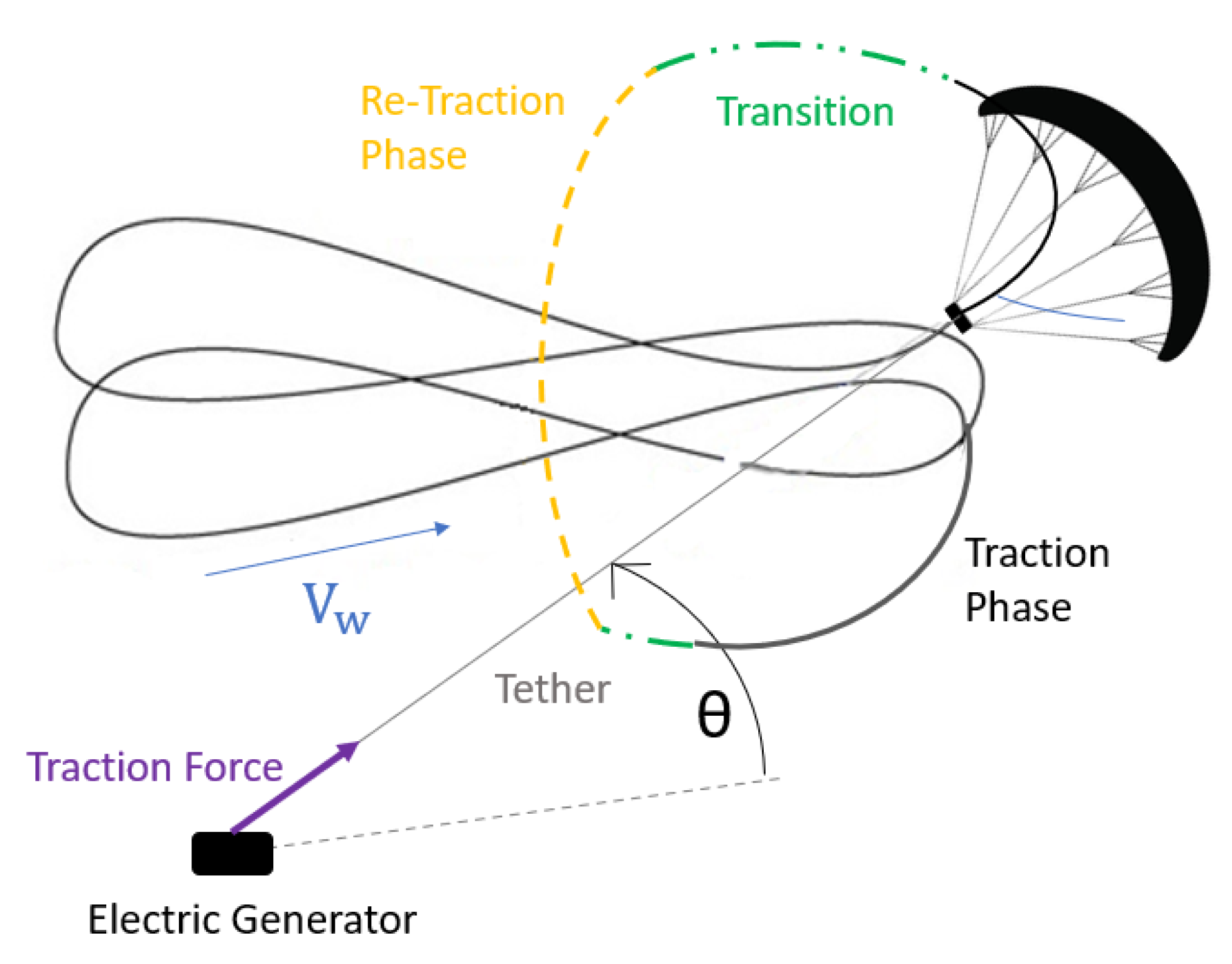
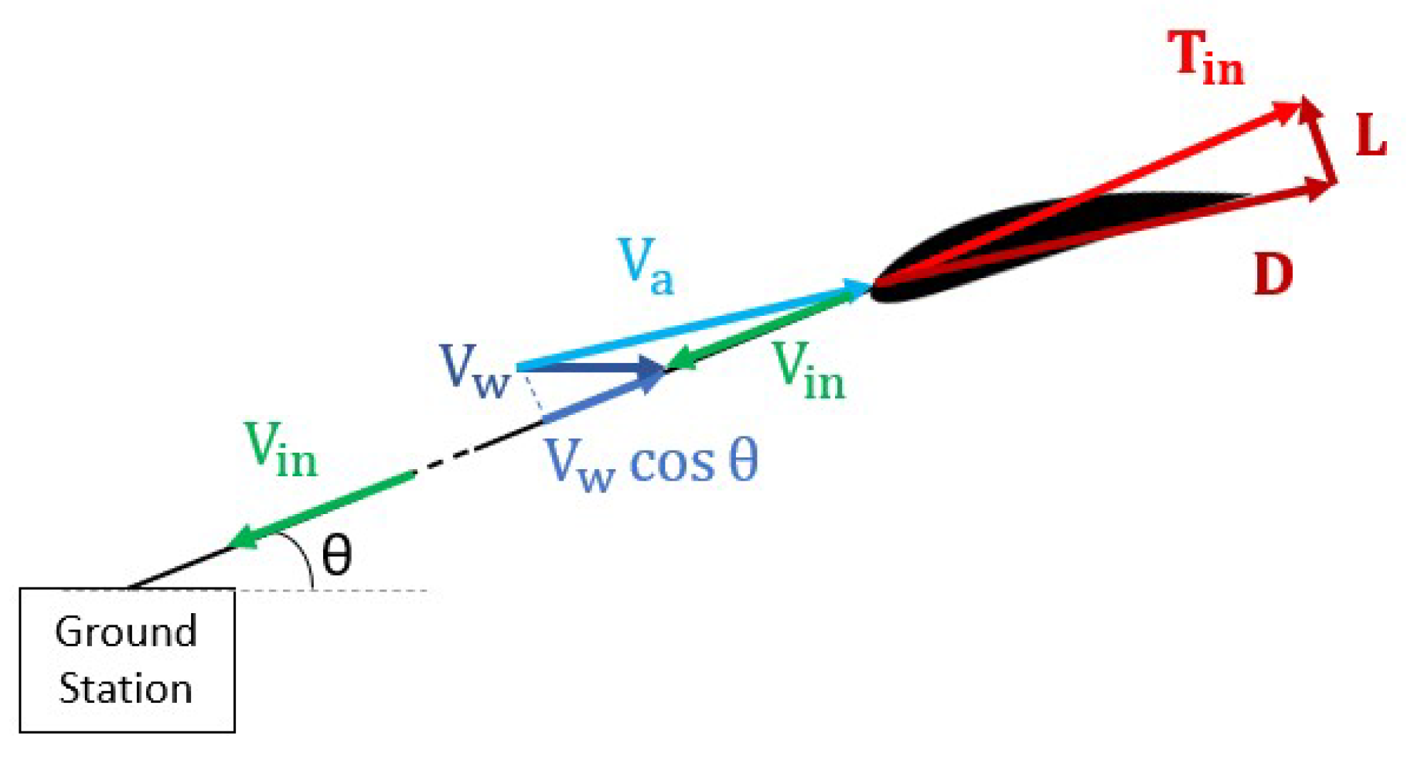
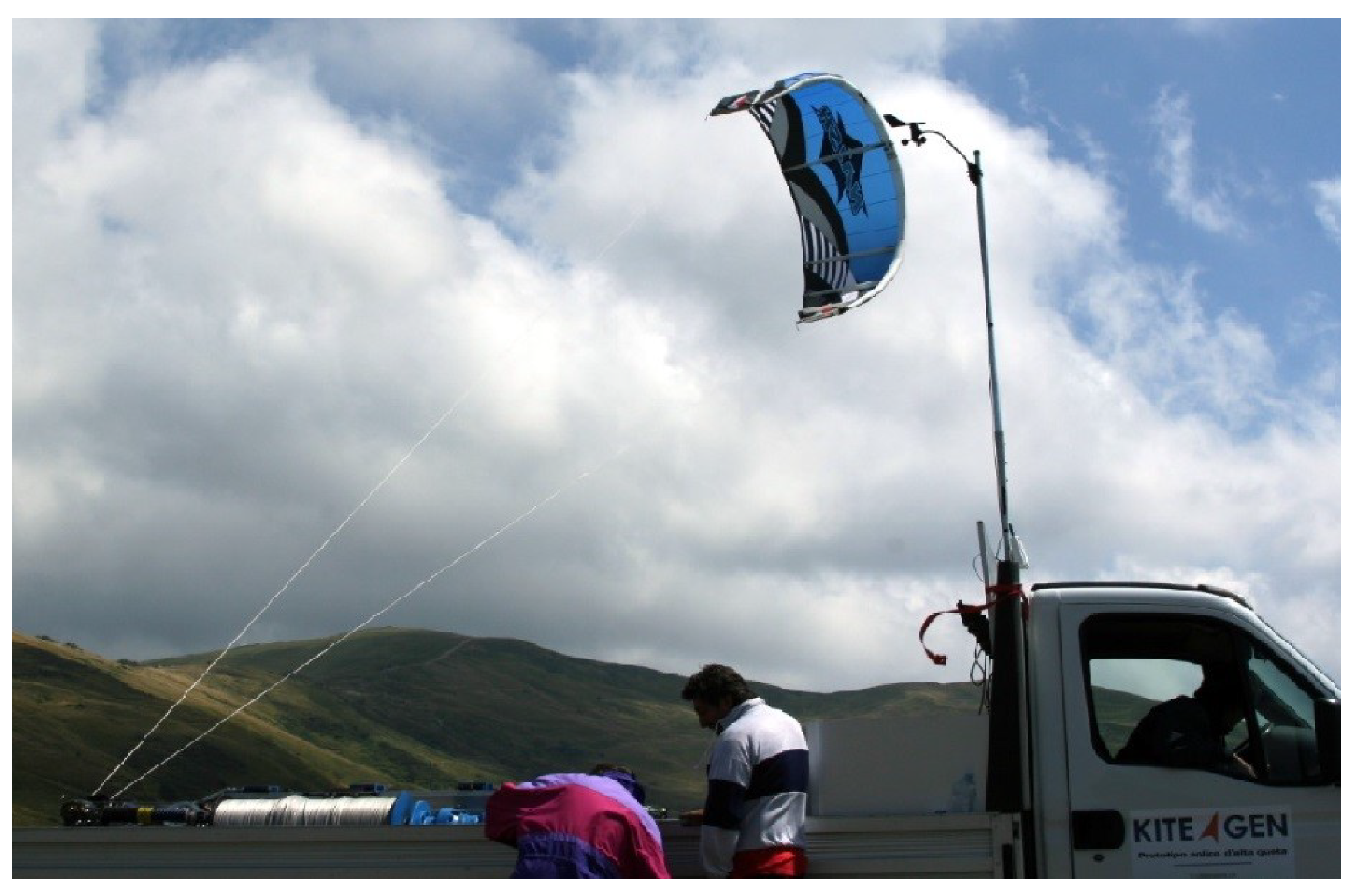
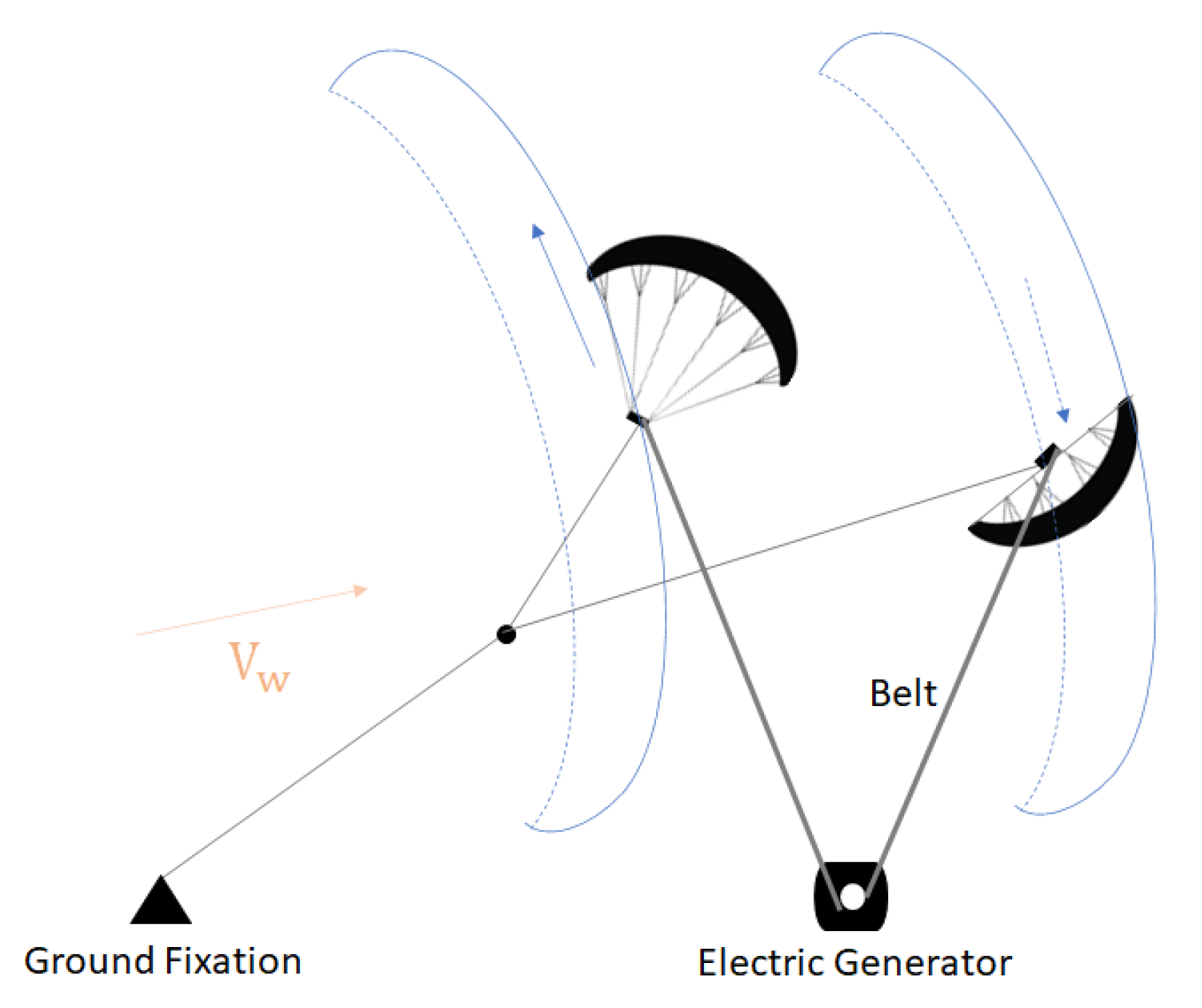
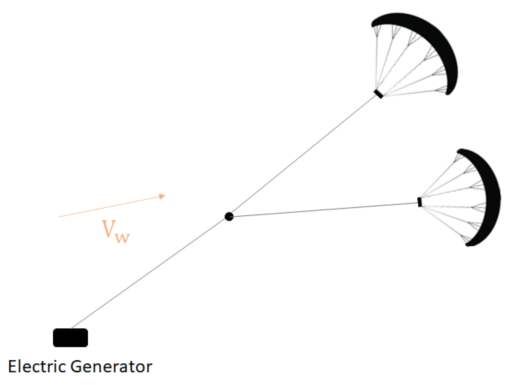
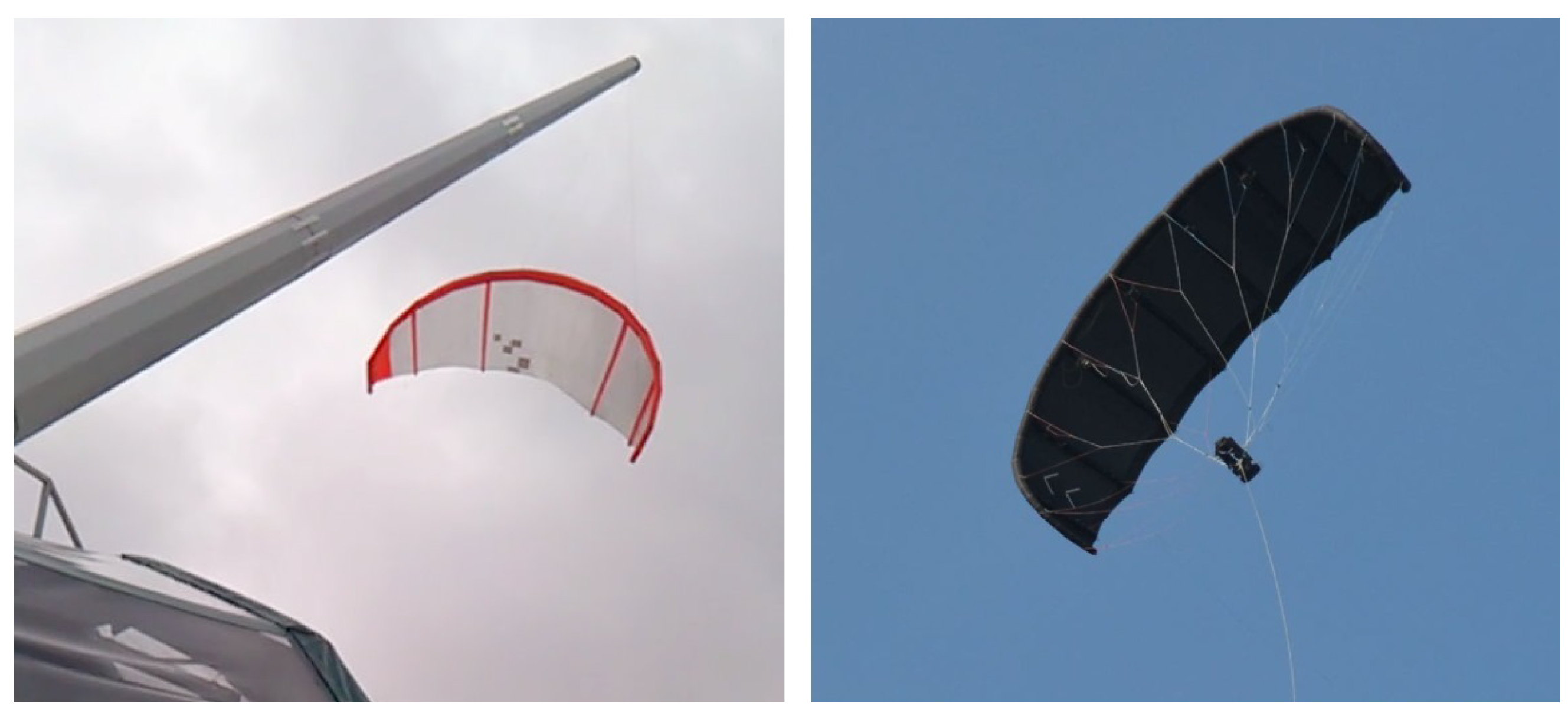
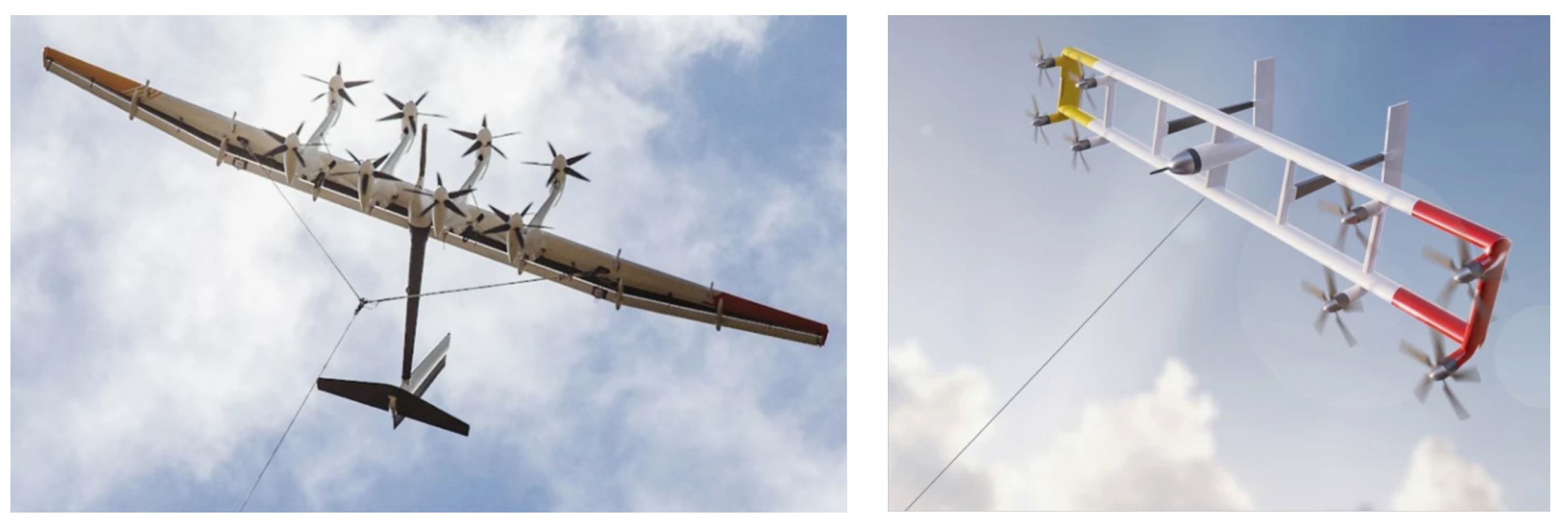
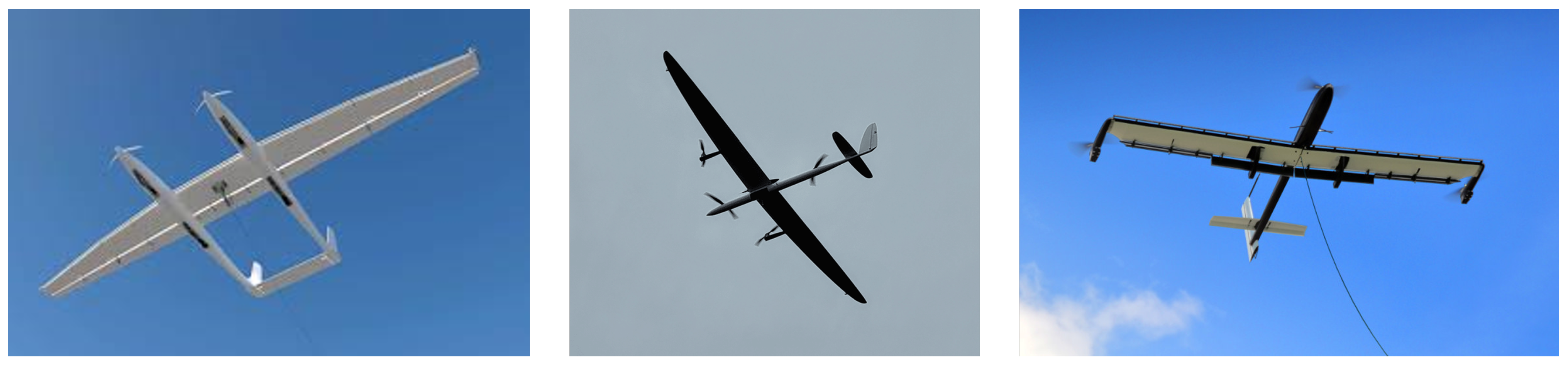
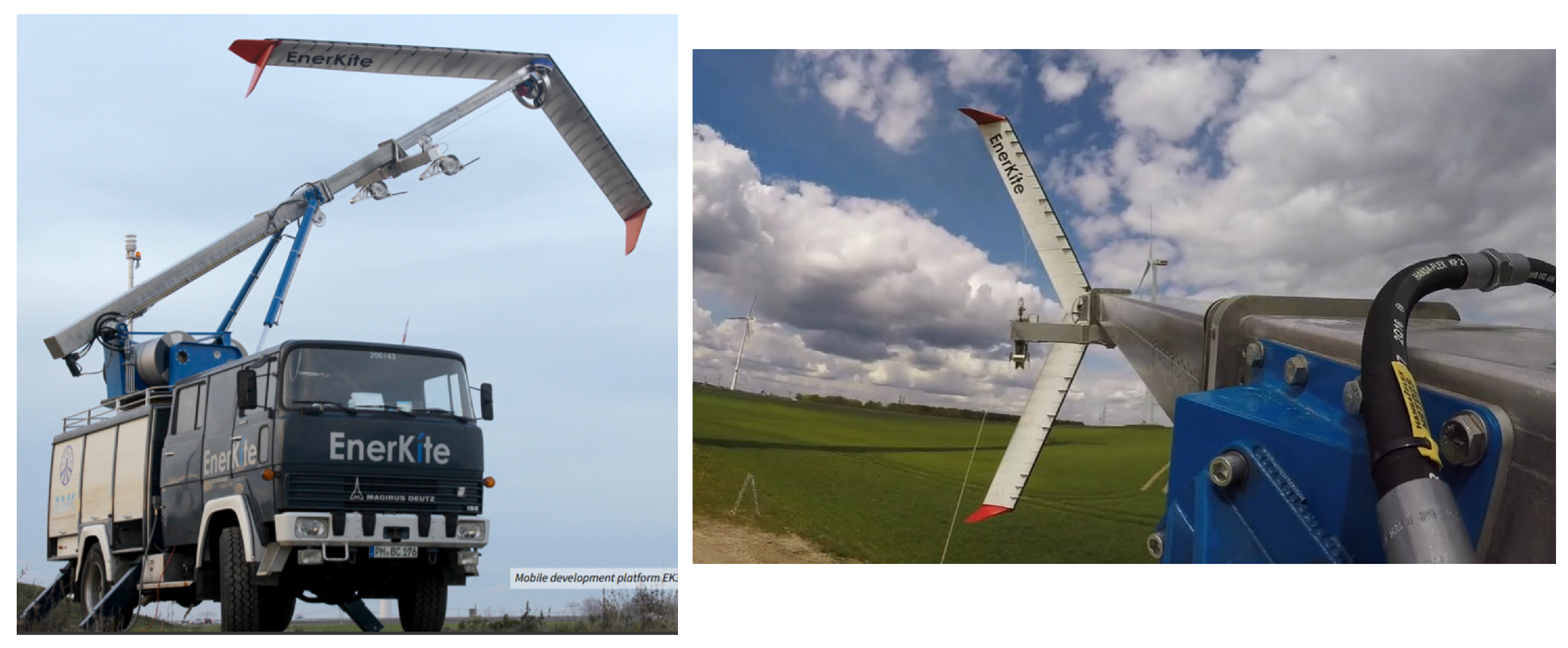
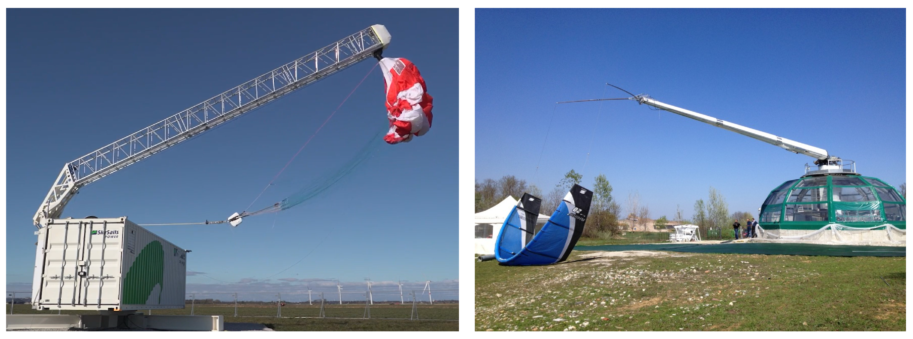
Table 1.
Summary of the technological characteristics that perform better in technical design factors.
Table 1.
Summary of the technological characteristics that perform better in technical design factors.
| Factor | Desired Characteristics |
|---|---|
| Aerodynamic Performance | ∘ Rigid wing—monoplane for on-ground generation and biplane for on-board generation. ∘ Thin tether-on-ground generation system. |
| Mass-to-Area Ratio | ∘ Soft wing, namely, an LEI wing. ∘ With rigid wing, an on-ground generation system is preferred. |
| Durability | ∘ Rigid wing. ⟹ On-board generation ∘ Constant length tether in energy production operation. system. |
| Survivability | ∘ Soft wing, namely, a ram-air wing. ∘ On-ground steering system and/or on-board control |
Table 2.
Summary of the technological characteristics that perform better in operational factors.
| Factor | Desired Characteristics |
|---|---|
| Continuity of Power Production | ∘ On-board generation system, using a rigid wing. ∘ If using a soft wing, an LEI kite is preferred. |
| Controllability | ∘ On-board actuation for a rigid wing and an airborne control unit for a soft wing. ∘ Operation of an on-board generation system. |
| Take-off/Landing Feasibility | ∘ Linear vertical maneuver, with the aircraft horizontally oriented, using a rigid wing. ∘ Passive approach with an elevating tower, using a soft wing. |
Table 3.
Summary of the technological characteristics that perform better in fabrication and logistical factors.
Table 3.
Summary of the technological characteristics that perform better in fabrication and logistical factors.
| Factor | Desired Characteristics |
|---|---|
| Manufacturability | ∘ Soft wing. ∘ Considering only the tether and electronics, an on-board generation system is preferred. |
| Logistics | ∘ On-ground platforms, with no additional towers or (rotating) arms. |
Table 4.
Summary of the technological characteristics that perform better in social acceptability factors.
Table 4.
Summary of the technological characteristics that perform better in social acceptability factors.
| Factor | Desired Characteristics |
|---|---|
| Visual Impact | ∘ Rigid wing. ∘ Flat on-ground platform. ∘ On-board generation system. |
| Noise Impact | ∘ On-ground generation system. ∘ Passive take-off/landing approach. ∘ On-ground generation system. |
| Ecological Impact | ∘ Soft wing. ∘ On-board generation. |
| Safety | ∘ Effective control systems. ∘ Well-isolated tethers. |
Disclaimer/Publisher’s Note: The statements, opinions and data contained in all publications are solely those of the individual author(s) and contributor(s) and not of MDPI and/or the editor(s). MDPI and/or the editor(s) disclaim responsibility for any injury to people or property resulting from any ideas, methods, instructions or products referred to in the content. |
© 2022 by the authors. Licensee MDPI, Basel, Switzerland. This article is an open access article distributed under the terms and conditions of the Creative Commons Attribution (CC BY) license (https://creativecommons.org/licenses/by/4.0/).
Share and Cite
MDPI and ACS Style
Pereira, A.F.C.; Sousa, J.M.M. A Review on Crosswind Airborne Wind Energy Systems: Key Factors for a Design Choice. Energies 2023, 16, 351. https://0-doi-org.brum.beds.ac.uk/10.3390/en16010351
AMA Style
Pereira AFC, Sousa JMM. A Review on Crosswind Airborne Wind Energy Systems: Key Factors for a Design Choice. Energies. 2023; 16(1):351. https://0-doi-org.brum.beds.ac.uk/10.3390/en16010351
Chicago/Turabian StylePereira, André F. C., and João M. M. Sousa. 2023. "A Review on Crosswind Airborne Wind Energy Systems: Key Factors for a Design Choice" Energies 16, no. 1: 351. https://0-doi-org.brum.beds.ac.uk/10.3390/en16010351
Note that from the first issue of 2016, this journal uses article numbers instead of page numbers. See further details here.