Article

Improvement of the Electrical Performance of Outdoor Porcelain Insulators by Utilization of a Novel Nano-TiO2 Coating for Application in Railway Electrification Systems

by
Pichai Muangpratoom
1,*,
Issaraporn Khonchaiyaphum
2 and
Wanwilai Vittayakorn
3
1
High-Voltage Insulation Technology and Innovation Research Unit (HVRU-RMUTI), Department of Electrical Engineering, Faculty of Engineering, Rajamangala University of Technology Isan, Khon Kaen Campus, Khon Kaen 40000, Thailand
2
Department of Mathematics, Faculty of Engineering, Rajamangala University of Technology Isan, Khon Kaen Campus, Khon Kaen 40000, Thailand
3
Electroceramics Research Laboratory (ECRL), College of Materials Innovation and Technology, King Mongkut’s Institute of Technology Ladkrabang, Bangkok 10520, Thailand
*
Author to whom correspondence should be addressed.
Submission received: 8 December 2022 / Revised: 23 December 2022 / Accepted: 28 December 2022 / Published: 3 January 2023
(This article belongs to the Special Issue Testing, Monitoring and Diagnostic of High Voltage Equipment)

Abstract

:
The present study aimed to develop the electrical performance of outdoor insulators using a nano-TiO2 coating for railway electrification systems. The prototype design of porcelain insulators with normal coatings and using a nano-TiO2 coating is based on IEC 60815-1. The first test was performed to measure the low-frequency flashover AC voltage under both dry and wet conditions. In addition, the other test was conducted to measure the lightning impulse critical-flashover voltage at positive and negative polarity under dry-normal and wet-contaminated conditions. X-ray diffraction (X-RD) and Scanning electron microscopy (SEM) were used to examine the micro surface and show that the nano-TiO2 coating was adhered to the surface of the outdoor porcelain insulator and exists in an amorphous state. Additionally, it was observed and discovered that scattered nano-TiO2 strengthens the glassy matrix and creates a sturdy barrier that causes flashover voltage to be reduced under conditions of high dielectric strength. Nanostructured ceramic formulations outperform ordinary porcelain in terms of breakdown voltage strength, particularly for the insulators’ low-frequency flashover performances under dry and wet test conditions. However, a significant change in the lightning impulse critical-flashover voltage characteristics is observed and is not much better when adding the nano-TiO2 coating to the porcelain insulators.

1. Introduction

An important component of any electrical system is insulation. This includes gas insulation, such as SF6, and liquid insulation, such as transformer oil or mineral oil, and solid insulation in transformers or cables, such as kraft paper or pressboard. In addition, there are important insulators that are used on the outside, such as the high-voltage porcelain insulators on the outside of transformer bushings, cutouts, arresters, line posts, etc. [1]. To last for years, they must meet strict electrical, mechanical, and chemical requirements, such as not breaking down when exposed to UV light or when in a dirty environment [2,3,4]. Although polymeric insulators have just lately been available, porcelain and glass have been used as outside insulators in electric power systems for over 160 years [5,6,7,8]. In the past, triaxial porcelain compositions of alumina, silica, clay, and feldspar were used to create ceramic insulators [1,9]. Insulators are one of the essential elements of railway electrification systems; however, the popular viewpoint does not give this essential component much attention. Economic considerations must be made in addition to the strict criteria for availability and dependability, which is why this topic is given a lot of attention [10]. The dependability of the performance of insulators, which are widely used in transmission power systems, is primarily influenced by environmental pollution. Composite insulators have been used for transmission lines for a long time because they work well even in dirty environments [11]. As compared to other ceramic materials, outdoor porcelain insulators are the subject of little research today that deals with nanotechnology applications. Nevertheless, it has been said that they have produced some very intriguing and encouraging outcomes. Porcelain is a policrystalline ceramic created by combining and burning clays, feldspathic minerals, and silica or alumina, and may be characterised as a conventional ceramic formed by heating raw materials based on clay [6,12]. In 2010, Zhuang et al. [13] investigated a novel use of nanoscale titanium dioxide (TiO2) for improving the performance of the porcelain insulator in contaminated settings. The researchers found that applying n-TiO2 films to the porcelain insulator’s surface maintains and even enhances the electrical characteristics of the AC wet flashover voltage (6%). To enhance the anti-icing performance of ceramic insulators utilised in China’s colder regions, Gou et al. created three novel experimental formulations of polymeric nanocoatings [14]. In order to enhance the mechanical and electrical performance of siliceous porcelain insulators, Contreras investigated a novel nanotechnology concept in 2014 [1].
At present, the rail system is of interest in the transportation system of Thailand. Therefore, it is important to research and develop the design of the components used in the rail system. In particular, the insulation in the railway electrification systems is one of the details of the overhead line electrification system for the railway, as can be seen in Figure 1. In addition, Thailand’s rail transport system uses an overhead power supply system to operate. Therefore, it is necessary to instal insulating materials, including outdoor porcelain insulators.There is very little research about the design and build of the porcelain insulator used in the electrification system for the railway in Thailand. Furthermore, most of these studies were about testing the durability of insulators, which included electrical tests.
This work was performed to improve the quality of the outdoor porcelain insulators used in the railway system and make it possible for electric trains to run on Thailand’s railway system. The porcelain insulator used in this railway system is extremely important because there is no manufacturer in Thailand, as they are primarily interested in producing insulators for the alternating current distribution system. As a result, the goal of this research is to develop the performance of outdoor insulators used in the railway’s overhead line electrification system. The performance-developed outdoor insulators of overhead line insulation equipment for railway electrification systems that use a nano-TiO2 coating would be the quality insulator that passes the standard electrical properties test.

2. Materials and Methods

2.1. The Design for Outdoor Insulators on Railway Electrification Systems

The prototype design of porcelain insulators based on international standards and the outdoor insulators on railway electrification systems used in Japanese and Spanish railway systems was studied, which included the equations used in the design of the leakage distance of insulators used in rail systems. Furthermore, the reference to the design of porcelain insulators, the insulator profile parameters as defined in IEC 60815-1 [15], the design considers the level of pollution that is used. Moreover, this research will design insulators that can be used at pollution levels of 1 and 2 based on IEC 60815-1. To determine the leakage distance of insulators, it is necessary to calculate the profile factor (PF) and the creepage factor (CF), which are important in the design of the fin length (measured from the core) and the distance between the fins, which includes the creepage distance and arcing distance of the insulators. Meanwhile, the values calculated from Equations (1) and (2) are evaluated to determine the suitability of insulating insulators for the design or application area. Previously, the sizes were as shown in Figure 2.
Profile Factor (P.F.)
P . F . = 2 P + S l d
when
  • P.F. > 0.8 for the pollution levels of 1 and 2 (light to medium pollution areas)
  • P.F. > 0.7 for the pollution levels of 3 and 4 (heavy to very heavy pollution areas)
Creepage Factor (C.F.)
C . F . = l t S t
when
  • C.F. ≤ 3.5 for the level of pollution 1 and 2 (light to medium pollution areas)
  • C.F. ≤ 4.0 for the level of pollution 3 and 4 (heavy to very heavy pollution areas)
The outdoor insulator profile parameters in this work, as defined in IEC60815-1, are as follows:
  • P: shed projection—the maximum shed overhang (35 mm).
  • S: shed spacing—the vertical distance between two points that are similar on successive sheds. (34.22 mm).
  • ld: Measured between the two places that constitute d is the creepage distance (70.34 mm).
  • lt: the insulator’s overall creepage distance (1050.30 mm).
  • St: the arcing distance of the insulator (442.44 mm).
The design variables were substituted into Equation (1) for P.F. and Equation (2) for C.F. So, the profile factor (P.F.) is equal to 1.482, which is more than 0.8 for the level of pollution in 1 and 2 (light to medium pollution areas). Moreover, the creepage factor (C.F.) is equal to 2.374, which is less than 3.5 for the level of pollution in 1 and 2 (light to medium pollution areas).
Therefore, the prototype outdoor insulators designed in this research were at pollution levels 1 and 2. It is standard practice on IEC60815.

2.2. Nanotechnology Concepts for Outdoor Insulators

This work presents new nanostructured porcelain composition coats for improving the electrical performance of outdoor porcelain insulators by using a novel application of nano-TiO2 coatings, including evaluating the effect of nano-TiO2 on the properties of conventional siliceous electrical porcelain for use in railway electrification systems. All the unprocessed nanomaterials employed in this investigation had an average particle size of ~40 nm. Additionally, they had a spherical form, and their analytical reagent quality was measured by TESCAN, Model: MIRA3, as seen in Figure 3.
The shape of nano-TiO2 is also shown in Figure 3a, where a quasi-spherical form is often seen. There could be some nano-TiO2 agglomerates present since no dispersant was utilised. Electron dispersive X-ray spectroscopy (EDS) was used to confirm the chemical composition of nano-TiO2, which is shown in Figure 3b. The properties of the nanoparticles employed in this work are listed in Table 1 [16]. Detailed properties of nano-TiO2 are specified by the manufacturer [16]. Titanium dioxide (titania) nanopowder, anatase. Specification: 99.9%; anatase; primary particle size ~40 nm (from SEM and BET surface area); BET multi-point specific surface area (SSA) >40 m2/g; spray-dry agglomerated to ~50 microns for easy handling.
The key ideas in this study for the outdoor porcelain insulators used in the railway system represent a novel approach to improving the final characteristics of outdoor high-voltage insulators. In addition, the porcelain raw materials utilised in this study were of industrial quality and were quartz, kaolinite clay, and sodium feldspar, which are all employed in the production of outdoor insulators according to the expertise of Asian Insulators Public Company Limited. Figure 4 shows that the main use of nanotechnology in this outdoor insulator by nano-TiO2 coating is to improve efficiency, mostly by making the electrical performance better.
Figure 4 illustrates the design idea for the aforementioned procedure. The link between a material’s resistivity, length, and the area is shown by the well-known Equation (3) [17].
R = ρ L A
where R stands for resistance, ρ for resistivity, L for the distance that charges travel before leaving the material, and A for the cross-sectional area of the material that faces the direction of the current. The R will decrease if we shorten L, raise A, or decrease ρ , as shown by Equation (3).
For the purposes of this study, we will refer to ρ as the resistivity of the nano-TiO2 coating, L as the thickness of the nano-TiO2 film, and A as the surface area of the graphite felt used for the nano-TiO2 film deposition. Thus, lowering the size and L of the nano-TiO2 film is one of the development paths that might be explored in this study. In this work, a nano-TiO2 coating was formed on the outside insulators to shorten L in order to decrease the resistance (R) of the coating. On the other hand, a two-step procedure was employed to create a nano-TiO2 coating, which included first generating an amorphous film at a low temperature, and then increasing the temperature to crystallise the film. It is noted that a two-step technique may be used to create a nano-TiO2 coating [18,19,20]. Since a large number of grain boundary defects in the nano-TiO2 coating, the resistivity ( ρ ) of the nano-TiO2 coating can be effectively reduced. Besides, the nano-TiO2 coating structure can achieve low resistance.

2.3. Surface Modification of Outdoor Insulators

A thin nano-TiO2 layer was applied to the surface of outdoor insulators via the development of an insulator nano-TiO2 coating method for surface modification. The process includes six steps. The nanoparticles are mixed with deionized water. The nanoparticles must be weighed on a digital balance, and the particle content required is 0.1% wt of deionized water. TiO2 nanoparticles (nano-TiO2) combined with deionized water and a surfactant. The surfactants are organic compounds, which consist of two parts: the hydrophilic group and the hydrophobic group. Two different phases can come together. When a small amount of surfactant is added, two phases can be combined to form a single phase. In this research, a surfactant type, TERGITOL™ NP-6 Surfactant (Nonylphenol Ethoxylate) [21], which has properties as a non-ionic surfactant, was selected to be used as an ingredient in the preparation of nano-TiO2 coatings for outdoor porcelain insulators. Then, it is placed in the stirrer for 30 min at 60 °C, or until it diffuses, and put in the high-frequency ultrasonicator at 60 °C for 1 h to ensure the homogeneity of the liquids, as shown in Figure 5. The step, as shown in Figure 5, begins with weighing the normal coatings and nano-TiO2 coatings at the prescribed amount (a weight ratio of 2:1 between the normal coatings and nano-TiO2 coatings). The next process involves mixing two substances, including measuring, and controlling the coating viscosity at 30–45 Cps. and waiting for the next process. After that, the nano-TiO2 coatings are put into a chamber containing the coatings. The formed prototype insulator is then put on an automatic coating machine to process the coating. Lastly, the prototype insulator is put into a temperature-controlled kiln under control at 1300 °C for 60 h.

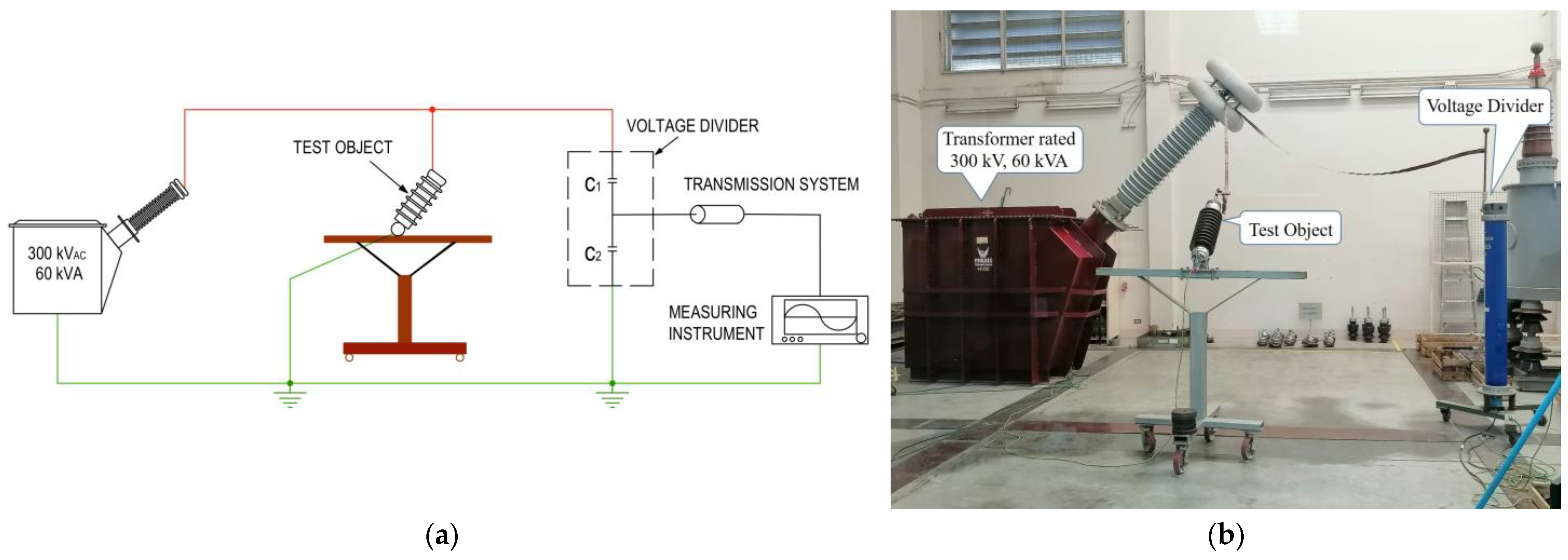
3. Experimental Descriptions

3.1. Performances of Standard Porcelain Insulators in Low-Frequency Flashover in Dry and Wet Test Conditions

When referring to low frequency, as defined in these standards, anything between 15 and 100 cycles per second is considered to be low frequency. The low-frequency testing described in these standards may be performed at any commercial frequency that is currently in use within this range. In Figure 6, a clean, dry test specimen voltage application’s root-mean-square (rms) voltage that results in a prolonged disruptive discharge through the air between electrodes is known as a low-frequency dry-flashover voltage. Approximately 75% of the anticipated average dry-flashover value may be rapidly reached by rapidly increasing the first applied voltage. The rate of voltage rise must remain constant after achieving 75% of the flashover value in order for there to be no time delay of more than 30 s or less than 5 s before the flashover occurs. An arithmetic mean, given in rms volts, of at least five different flashovers collected in a row constitutes the dry-flashover voltage value for a specimen. There must be between 15 s and 5 min of time between each flashover.
The low-frequency wet-flashover voltage is the root-mean-square (rms) voltage that causes a long, disruptive discharge between the electrodes of a clean, wet test specimen. The area where the insulator is being tested must have enough spray nozzles of the kind illustrated in Figure 7 or an equivalent supply of artificial precipitation that is fairly uniform. Within the limits of what is practically possible, the spray must be directed such that it strikes the insulator downward at a 45-degree angle from the vertical and parallel to the vertical plane across its axis. Large specimens, such as the outdoor porcelain insulators, must have spray that is 45 degrees off vertical in the middle and as near to this angle at the ends as feasible to provide adequate precipitation uniformity over the length of the specimen. At the specimen, the standard average rate of precipitation must be 0.2 inches (5.08 millimetres) per minute when measured. The low-frequency flashover AC voltage testing apparatus is shown in Figure 6 and Figure 7 for both dry and wet experiments, respectively. Phenix Technologies’ variants for the frequency output device are rated at 300 kV, 60 kVA, respectively, based on ANSI/NEMA C29.7-2015 [22], TIS 2623-2560 (2017) [23], and IEEE-4 (2013) [24].

3.2. The Lightning Impulse Critical-Flashover Voltage Performances of Standard Porcelain Insulators under Normal and Contaminated Test Conditions

A test specimen’s impulse critical-flashover voltage is equal to the wave’s peak value in 50% of applications. A lightning impulse critical-flashover voltage test in polluted circumstances was used in this study to assess the performance of prototype outdoor porcelain insulators. Normally, impulse-flashover experiments are only carried out in dry environments. There must be 1.2/50 μs of time between each impulse voltage wave. Applying impulses to the specimen of varied intensities and monitoring the peak voltage of the impulse that, in about 50% of applications, will result in flashover allows for the determination of the critical impulse flashover voltage value. Impulses must be applied in stages of rising or decreasing voltage such that at the step with the greatest voltage, flashover occurs on every impulse, and at the step with the lowest voltage, there is no flashover. At least three impulses must be applied at each voltage step, and the difference in voltage between steps must not be more than 5% of the anticipated critical impulse flashover value. When the voltage range between the highest and lowest step is quite large, it is possible to calculate the crucial impulse flashover voltage by plotting an average curve of crest voltage vs flashover frequency.
The experimental setup for testing the critical-flashover voltage for a lightning impulse in both dry and polluted conditions is shown in Figure 8 and Figure 9. The impulse voltage generator, whose rated voltage is 400 kV and 40 kJ under both normal and contaminated circumstances based on TIS 1077-2535 (1992) [25], TIS 2623-2560 (2017), and IEC 60507 (2013) [26], is used to acquire test power. The primary capacitor is charged to the desired voltage. The circuit is then automatically initiated by the spark gap to provide a positive polarity lightning discharge voltage of 1.2/50 μs. The experiment uses the up-and-down test methodology. A test was conducted in order to determine how effectively conventional porcelain insulators can tolerate impulses at both positive and negative polarities and in unclean circumstances. Furthermore, the surface of the specimens is polluted using test techniques on pollution flashover the suspension of sodium chloride and kieselguhr, which, respectively, imitate electric and inert materials. Based on the results of [27,28,29], the relationship between the critical flashover voltage representations of the electrical withstand value and the equivalent salt deposit density (ESDD) values is recommended as a contamination severity criterion for each case, as shown in Equation (4):
E s = λ ( E S D D ) μ
When the electrical voltage is withstood (Es), which is measured using experimental data from research and curve fitting, it is written as kV/cm and is related to the material and shape of the insulators. This research provides samples of contaminated liquid for testing under pollution conditions. By using the data for the contaminated liquid samples, values of ESDD can be calculated based on the procedure described in IEC 60507. The ESDD value obtained in this work is 0.4 mg/cm2.
For all experiments, the salt deposit density (SDD)/equivalent salt deposit density ratio is 1:6. At the top of the artificial climate chamber, the test specimen is mounted on a solid base made of non-conductive wood. Spray nozzles are used to spray the test specimen. A spray pipe that is located not far below the surface of the body of the housing carries the spray, and the spray mist input rate is (0.05 ± 0.01) kg/(h.m3) based on IEEE 4 (2013), and the fog chamber’s humidity is almost saturated to a wet condition [30]. Through exhausting and misting water, the mist chamber is cooled to match the ambient temperature. Once the insulator’s surface is suitably moist, the sample is left to stand for 15 to 20 min before the test is begun [26].

4. Results and Discussion

4.1. The Dielectric Strength

4.1.1. Low-Frequency Flashover Performance in Dry and Wet Testing Conditions

The influence of nano-TiO2 on the low-frequency flashover AC voltage under dry and wet tests of the prototype outdoor porcelain insulator sample is shown in Table 2. It was discovered that adding nano-TiO2 encouraged an improvement in the dielectric capacity of regular porcelain.
Figure 10a depicts dry test results with the nano-TiO2 concentration used in this study (0.1 wt.%), with the breakdown voltage reaching an average of 174.28 kV at 0.1 wt.% nano-TiO2 addition and 172.81 kV at 0 wt.% nano-TiO2 addition (uncoated nano-TiO2). Using a new way to use nano-TiO2 coatings on samples made the electrical performance of outdoor porcelain insulators 0.85% better than with regular porcelain.The effect of the nano-TiO2 on the low-frequency flashover AC voltage under wet tests of the porcelain insulator sample is depicted in Figure 10b. It was found that the addition of nano-TiO2 impacts the electrical performance of the porcelain insulator. When nanostructured porcelain with a nano-TiO2 coating was compared to regular porcelain (without a nano-TiO2-coating), it was better by 1.06%. Due to the inclusion of nanoparticles, the sintered microstructure has changed, which may be the cause of this behavior. According to [31,32], a larger concentration of the vitreous phase has a negative impact on the dielectric breakdown because the crystalline/glassy phase ratio affects the electric characteristics of porcelain systems. Due to a lower proportion of glassy phase than normal porcelain, nanostructured porcelain exhibits greater breakdown voltage values. This behaviour may be made possible by the optimization of the electrical design of insulators. Without a doubt, adding nano-TiO2 to the prototype outdoor porcelain insulator makes its electrical properties better.

4.1.2. The Lightning Impulse Critical-Flashover Voltage Performance under Normal and Contaminated Test Conditions
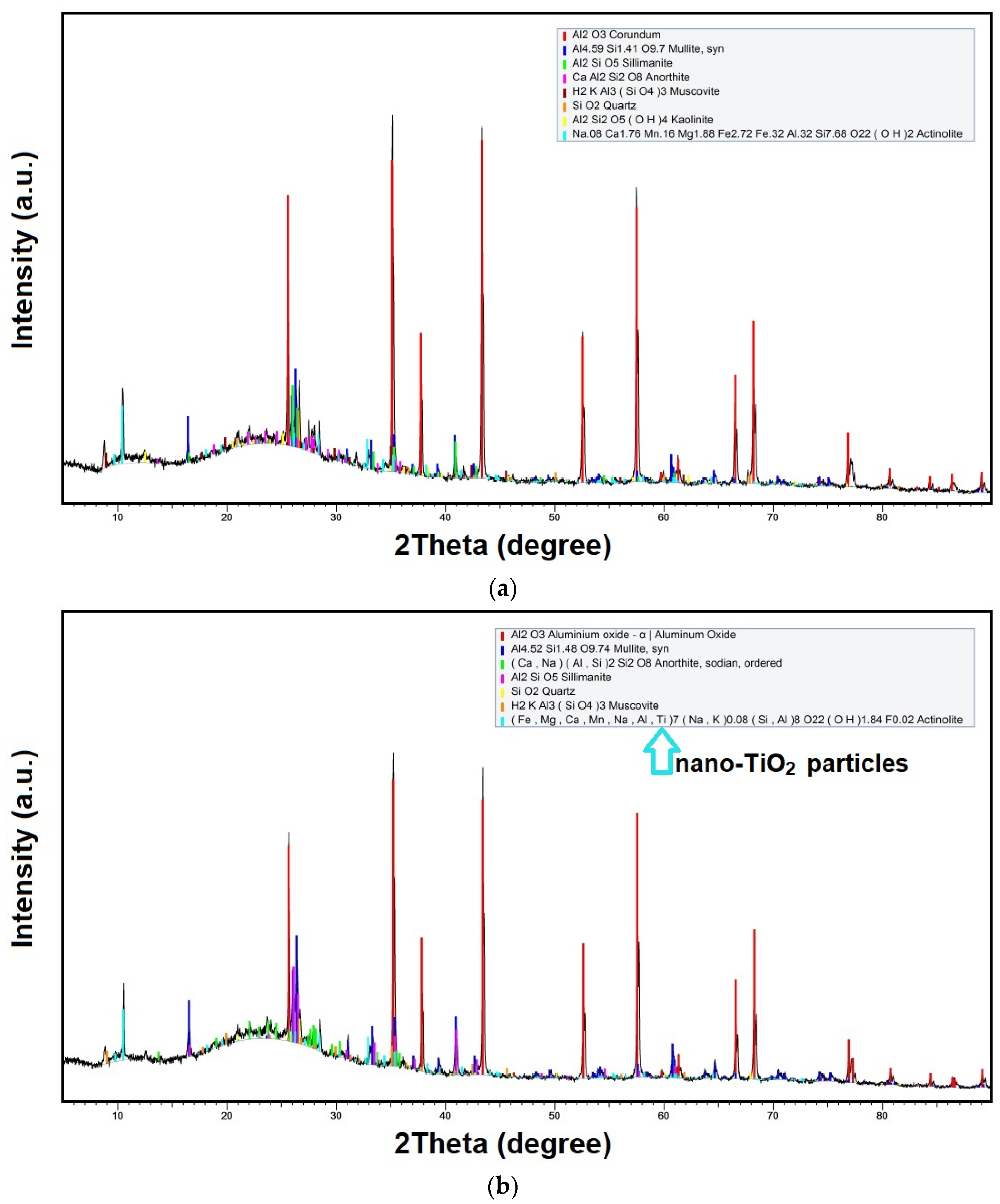
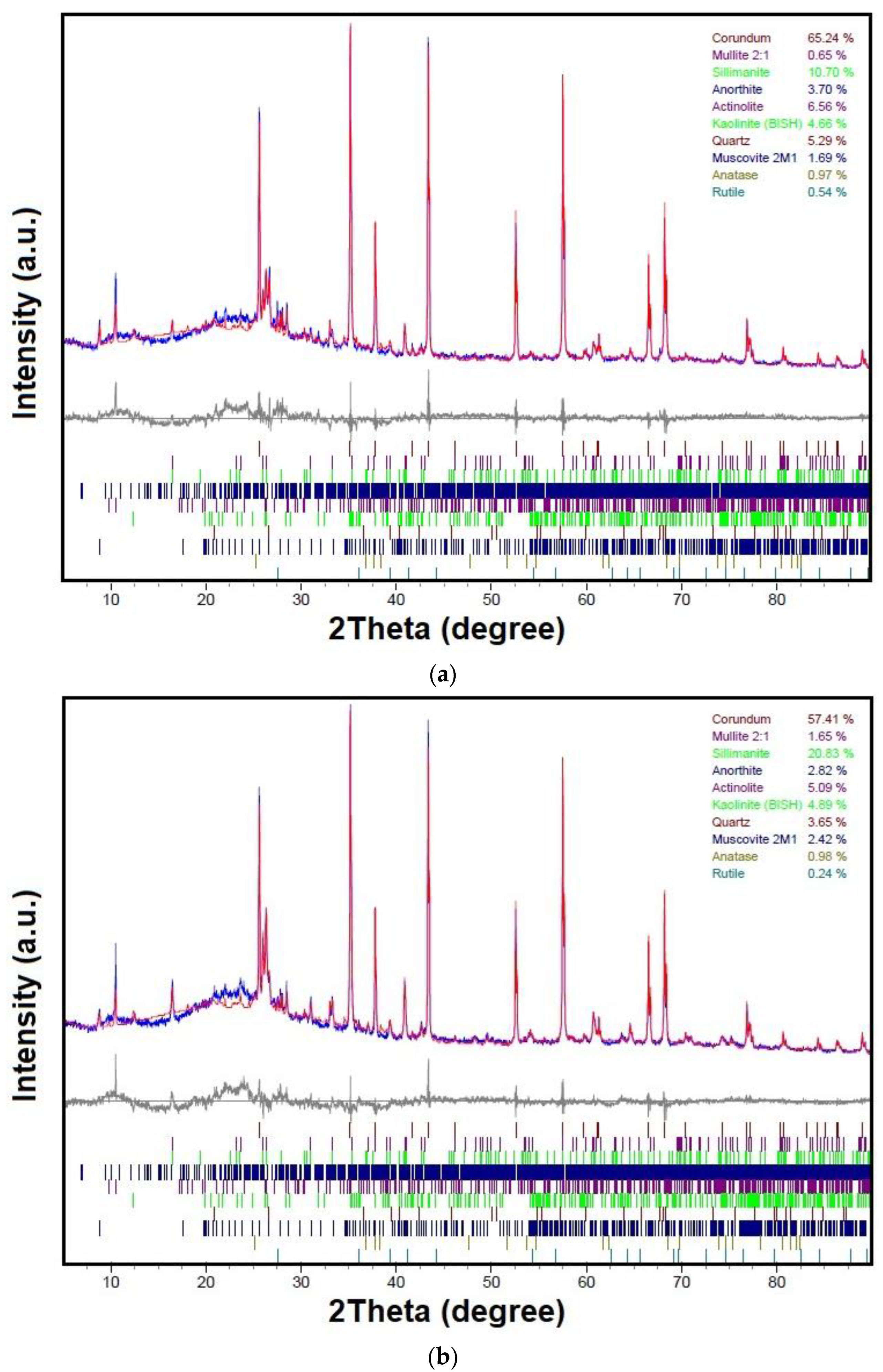
A comparison of the critical impulse flashover voltage is illustrated in Table 3. In Figure 11, under normal test conditions, both positive and negative lightning impulses, the nano-TiO2 coated insulators had a slight increase in dielectric strength compared to traditional coated insulators. In the same way, Figure 12 shows the critical impulse flashover voltage value under contaminated test conditions. When the nano-TiO2 coating was added to the porcelain insulators, there was only a slight improvement in the changes under positive polarity testing, and in the negative polarity testing, there was no significant change in the characteristics of the lightning impulse critical-flashover voltage. The electrical performance test results are less than 2%, according to the results. It may be because the nano-TiO2 content is so low (only 0.1 wt.%) that it does not show a clear effect on the electrical properties of the coated insulators with improved coating as much as it should. In the future, we may add more nano-TiO2 to show higher electrical values. Additionally, it is well known that under both positive and negative lightning impulses, the distribution of the electric field on the insulator’s surface is not uniform. The accumulation and growth of space charges would greatly distort the electric field across the air gap and reduce the flashover voltage [13,33]. Undoubtedly, one of the most effective ways to reduce the likelihood that charges will accumulate on the surface of an insulator is to decrease the surface resistivity [34]. Insulators are coated with nano-TiO2 to make the insulator surface diffuse the electric field and thus increase the lightning impulse voltage. Contrarily, the surface conductance of the TiO2-coated insulator is higher than that of the uncoated one, which might lead to an increase in leakage current and a decrease in flashover voltage. During testing, the U50% stays pretty much the same because these two opposing effects often cancel each other out [13].

4.2. Phase Analysis

The prototype scale study’s comparative XRD analysis of traditional porcelain systems and nanostructured porcelain systems in the sintered condition. Figure 13 shows the XRD patterns of prototype porcelain insulators with conventional coatings and nano-TiO2 coatings measured by the Bruker D2 phaser at 30 kV, 10 mA. The results of this study revealed that the primary crystalline phases in the porcelain insulator prototype composition were quartz (SiO2) and mullite (3Al2O3•2SiO2). The primary crystalline phases of the nanostructured porcelain’s diffraction pattern remained the same, and corundum, an unaltered form of alumina, was also present. Figure 13a shows alumina peaks in formulations with a high proportion of traditional porcelain insulators. Furthermore, as illustrated in Figure 13b, adding a TiO2 layer to the surface of outdoor insulators improves mullite peak intensity. Additionally, the fraction of crystalline phases rise with the inclusion of nanoparticles. It is important to note that the phase concentrations of all the samples match the published values for porcelain insulators [6,35,36]. The data for the prototype porcelain insulators with regular coatings and with a nano-TiO2 coating were refined using the Rietveld method to produce crystallographic data, which was then used to further characterise the XRD findings. The lattice parameters, atomic coordinates, and atomic occupancies of manufactured materials may all be examined using the Rietveld refinement method, are displayed in Figure 14.
The Rietveld refinement was carried out on porcelain insulators with normal coatings, and a nano-TiO2 coating was used to analyse the crystal structure of the porcelain materials. Figure 14 shows the Rietveld refinement plot of the triaxial ceramic fired at 1300 °C. In this work, the observed XRD patterns and the structural model showed convergence with good weight profile R values (Rwp). The R values, Rietveld refinement, Residual values, or Rietveld discrepancy indices are all names for the numerical approach of evaluating the quality or goodness of fit, which is often expressed in terms of agreement indices [37]. The weighted profile R values are the easiest to understand because they come straight from the square root of the minimum amount, which is scaled using weighted intensities. Typical values of Rwp range from a few per cent for very accurate refinements to 20–30% for X-ray refinements, depending in part on the counting times used, the degree of preferred orientation, and the number of variable parameters [38,39]. The refinements were adequate. Indeed, the Rwp values were, in all cases, between 10 and 30%. Furthermore, in all samples, the estimated standard deviation of weight per cent derived from the estimated standard deviations of individual scale factors for the respective phases was below 1.5%. In particular, when considering the comparisons from Figure 14a and Figure 14b, the graphs show the percentage of the substance content on all the samples of insulating coating. Moreover, it can be seen that when nano-TiO2 coatings are applied to insulators, they result in higher percentages of mullite, and sillimanite compared to insulators using traditional coatings. The results obtained from Rietveld refinement are consistent with the XRD results shown in Figure 13.

4.3. Microstructural Analysis

Figure 15 and Figure 16 depict the sintered microstructure that corresponds to the prototype porcelain insulator design based on international standards and the outdoor insulator composition used in industrial-scale railway electrification systems. Using the SEM and EDS methods in the back-scattered electron mode, and spectrum and quantity analysis were measured by TESCAN, Model: MIRA3. We compared the porcelain insulators with traditional coatings in Figure 15 and nano-TiO2 coatings in Figure 16.
In a glassy matrix with a consistent distribution of quasi-spherical pores, coarse quartz grains with variable shapes make up a typical siliceous porcelain microstructure. There are noticeable fissures all around the quartz grains. This occurrence is linked to the sample cooling stage after the prototype insulator has been burnt at 1300 °C for 60 h in a temperature-controlled kiln when the quartz grain volume falls by 2% because of the β-α quartz-phase transformation [7,31]. This shift may cause enough strain to cause both the glassy matrix and the quartz grains to crack because of the large difference in thermal expansion between the quartz grains, which have a coefficient of thermal expansion of 23 × 10−6 C−1, and the glassy phase that surrounds them, which has a coefficient of thermal expansion of 3 × 10⁻⁶ C−1 (at temperatures between 20 and 700 °C). The size of the quartz particles and the rate at which they cool cause a reduction in the porcelain’s mechanical and dielectric strength [31].

5. Conclusions

The test results concluded that when adding nano-TiO2 at 0.1 wt.% of the amount of deionized water applications to outdoor insulators on railway electrification systems before processing coating and electrical testing, the performance of low-frequency flashover in dry and wet test conditions of the insulator coated with TiO2 was higher than that coated with the normal coating. Furthermore, the test results of the lightning impulse critical-flashover voltage performance under normal test conditions showed that the insulator coated with nano-TiO2 can cause a small change in the impulse breakdown voltage with both positive and negative polarity. Similarly, the positive polarity testing under contaminated test conditions, especially in the negative polarity of the impulse breakdown voltage, shows no improvement. However, it may be because the TiO2 content is so low (only 0.1 wt.%) that it does not show a clear effect on the electrical properties of the coated insulators with improved coating as much as it should. In the future, we may add more TiO2 to show higher electrical values. Finally, the results of this research showed that adding nano-TiO2 to improve the electrical properties of the insulator will likely improve its performance in the future.

Author Contributions

Conceptualization, P.M.; methodology, P.M.; investigation, P.M.; writing—original draft preparation, P.M.; data curation, I.K.; resources, P.M. and I.K.; formal analysis, W.V. and I.K.; writing—review and editing, W.V. All authors have read and agreed to the published version of the manuscript.

Funding

This research project is supported by Rajamangala University of Technology Isan. Contract No. ENG 22/63.

Data Availability Statement

Not applicable.

Acknowledgments

The authors would like to acknowledge Asian Insulators Public Company Limited for technical support to develop the performance of insulators on the application of nanomaterials used to coat a thin TiO2 film on the surface of porcelain insulators. Moreover, the authors are grateful to the Faculty of Engineering, Rajamangala University of Technology Isan, Khon Kaen Campus (RMUTI KKC), for providing the research support facility. A special thanks also to the high-voltage research team at the High Voltage Research Laboratory, RMUTI KKC.

Conflicts of Interest

The authors declare no conflict of interest.

References

  1. Contreras, J.E.; Rodriguez, E.A.; Taha-Tijerina, J. Nanotechnology applications for electrical transformers—A review. Electr. Power Syst. Res. 2017, 143, 573–584. [Google Scholar] [CrossRef]
  2. Eisawy, E.A. The Effect of Radiation Environment on Electrical Insulation Materials. J. Nucl. Radiat. Phys. 2019, 14, 11–20. [Google Scholar]
  3. Montoya, G.; Hernández, R.; Montoya, J. Failures in outdoor insulation caused by bird excrement. Electr. Power Syst. Res. 2010, 80, 716–722. [Google Scholar] [CrossRef]
  4. McAfee, R.; Heaton, R.; King, J.; Falster, A. A study of biological contaminants on high voltage porcelain insulators. Electr. Power Syst. Res. 1997, 42, 35–39. [Google Scholar] [CrossRef]
  5. Gubanski, S.M. Outdoor high voltage insulation. IEEE Trans. Dielectr. Electr. Insul. 2010, 17, 325. [Google Scholar] [CrossRef]
  6. Contreras, J.E.; Gallaga, M.; Rodriguez, E.A. Effect of Nanoparticles on Mechanical and Electrical Performance of Porcelain Insulator. In Proceedings of the 2016 IEEE Conference on Electrical Insulation and Dielectric Phenomena (CEIDP), Toronto, ON, Canada, 16–19 October 2016; pp. 583–586. [Google Scholar]
  7. Meng, Y.; Gong, G.; Wu, Z.; Yin, Z.; Xie, Y.; Liu, S. Fabrication and microstructure investigation of ultra-high-strength porcelain insulator. J. Eur. Ceram. Soc. 2012, 32, 3043–3049. [Google Scholar] [CrossRef]
  8. Hackam, R. Outdoor HV composite polymeric insulators. IEEE Trans. Dielectr. Electr. Insul. 1999, 6, 557–585. [Google Scholar] [CrossRef]
  9. Carty, W.M.; Senapati, U. Porcelain-raw materials, processing phase evolution, and mechanical behavior. J. Am. Ceram. Soc. 1998, 81, 3–20. [Google Scholar] [CrossRef]
  10. Morocutti, T.; Berg, T.; Muhr, M.; Gödel, G. Developments of High Voltage Porcelain Post Insulators. In Proceedings of the 2012 IEEE International Symposium on Electrical Insulation, San Juan, PR, USA, 10–13 June 2012; pp. 395–398. [Google Scholar]
  11. Monire, T.; Mostafa, S.; Nasim, N.; Alireza, S.F. Reliability assessment of RTV and nano-RTV-coated insulators concerning contamination severity. Electr. Power Syst. Res. 2021, 191, 106892. [Google Scholar]
  12. Hossain, S.S.; Roy, P.K. Sustainable ceramics derived from solid wastes: A review. J. Asian Ceram. Soc. 2020, 8, 984–1009. [Google Scholar] [CrossRef]
  13. Zhuang, J.; Liu, P.; Dai, W.; Fu, X.; Li, H.; Zeng, W.; Liao, F. A novel application of nano nticontamination technology for outdoor high-voltage ceramic insulators. Int. J. Appl. Ceram. Technol. 2010, 7, E46–E53. [Google Scholar] [CrossRef]
  14. Guo, C.; Liao, R.; Yuan, Y.; Zuo, Z.; Zhuang, A. Glaze icing on superhydrophobic coating prepared by nanoparticles filling combined with etching method for insulators. J. Nanomater. 2015, 2015, 404071. [Google Scholar] [CrossRef]
  15. IEC/TS 60815-1. Selection and Dimensioning of High-Voltage Insulators Intended for Use in Polluted Conditions; International Electrotechnical Commission: Geneva, Switzerland, 2008. [Google Scholar]
  16. Inframat Advanced Materials LLC. Available online: http://www.advancedmaterials.us (accessed on 18 May 2022).
  17. Wen-Jen, L.; Yu-Ting, W.; Yi-Wei, L.; Yen-Ting, L. Graphite Felt Modified by Atomic Layer Deposition with TiO2 Nanocoating Exhibits Super-Hydrophilicity, Low Charge-Transform Resistance, and High Electrochemical Activity. Nanomaterials 2020, 10, 1710. [Google Scholar]
  18. Lee, W.J.; Hon, M.H.; Chung, Y.W.; Lee, J.H. A three-dimensional nanostructure consisting of hollow TiO2 spheres fabricated by atomic layer deposition. Jpn. J. Appl. Phys. 2011, 50, 06GH06. [Google Scholar] [CrossRef]
  19. Moya, A.; Kemnade, N.; Osorio, M.R.; Cherevan, A.; Granados, D.; Eder, D.; Vilatela, J.J. Large area photoelectrodes based on hybrids of CNT fibres and ALD-grown TiO2. J. Mater. Chem. A. 2017, 5, 24695–24706. [Google Scholar] [CrossRef] [Green Version]
  20. Li, M.; Zu, M.; Yu, J.; Cheng, H.; Li, Q.; Li, B. Controllable synthesis of core-sheath structured aligned carbon nanotube/titanium dioxide hybrid fibers by atomic layer deposition. Carbon 2017, 123, 151–157. [Google Scholar] [CrossRef]
  21. Surfactants, Emulsifiers and Polyglycols High Performance Products. Available online: https://www.dow.com/en-us/product-technology/pt-surfactants-emulsifiers-polyglycols.html (accessed on 24 September 2022).
  22. ANSI/NEMA C29.7-2015; American National Standard for Wet-Process Porcelain Insulators-High-Voltage Line Post-Type. National Electrical Manufacturers Association (NEMA): Rosslyn, Virginia USA, 2015.
  23. TIS 2623-2560; Electrical power insulators Part 1 Test methods. Thai Industrial Standards: Bangkok, Thailand, 2017.
  24. IEEE Std 4; IEEE Standard for High-Voltage Testing Techniques. IEEE Power and Energy Society: New York, NY, USA, 2013.
  25. TIS 1077-2535; Line-Post Type Porcelain Insulators. Thai Industrial Standards: Bangkok, Thailand, 1992.
  26. IEC/TS 60507; Artificial Pollution Tests on High Voltage Insulators to be Used on A. C. Systems. International Electrotechnical Commission: Geneva, Switzerland, 2013.
  27. Baker, A.C.; Farzaneh, M.; Gorur, R.S.; Gubanski, S.M.; Hill, R.J.; Karady, G.G.; Schneider, H.M. Insulator selection for AC overhead lines with respect to contamination. IEEE Trans. Power Deliv. 2009, 24, 1633–1641. [Google Scholar] [CrossRef]
  28. Ashwini, A.; Ravi, K.; Vasudev, N. Experimental Study on Aging of Polymeric Insulators by Dip Method. In Proceedings of the 2019 International Conference on High Voltage Engineering and Technology (ICHVET), Hyderabad, India, 7–8 February 2019; pp. 1–3. [Google Scholar]
  29. Mohammad, R.A.V.; Mohammad, M.; Reza, S. Reliability assessment of aged SiR insulators under humidity and pollution conditions. Int. J. Electr. Power Energy Syst. 2020, 117, 105679. [Google Scholar]
  30. Bowen, W.; Jiazheng, L.; Zhen, F.; Zhenglong, J.; Jianping, H. Development of Antithunder Composite Insulator for Distribution Line. IEEJ Trans. Electr. Electron. Eng. 2019, 15, 100–107. [Google Scholar]
  31. Contreras, J.E.; Taha-Tijerina, J.; Lopez-Perales, J.F.; Banda-Munoz, F.; Díaz-Tato, L.; Rodríguez, E.A. Enhancing the quartz-clay-feldspar system by nano-Al2O3 addition for electrical insulators: From laboratory to prototype scale. Mater. Chem. Phys. 2021, 263, 124289. [Google Scholar] [CrossRef]
  32. Chaudhuri, S.P.; Sarkar, P.; Chakraborty, A.K. Electrical resistivity of porcelain in relation to constitution. Ceram. Int. 1999, 25, 91–99. [Google Scholar] [CrossRef]
  33. Srivastava, K.D.; Zhou, J.P. Surface Charging and Flashover of Spacers in SF6 Under Impulse Voltages. IEEE Trans. Electr. Insul. 1991, 26, 428–442. [Google Scholar] [CrossRef]
  34. Miller, H.C.; Furno, E.J. The Effect of Mn/Ti Surface Treatment on Voltage-Holdoff Performance of Alumina Insulators in Vacuum. J. Appl. Phys. 1978, 49, 5416–5420. [Google Scholar] [CrossRef]
  35. Iqbal, Y.; Lee, W. Fired porcelain microstructures revisited. J. Am. Ceram. Soc. 1999, 82, 3584–3590. [Google Scholar] [CrossRef]
  36. Xu, R. The compositions and properties of electric porcelain materials in China. In Proceedings of the Second International Conference on Properties and Applications of Dielectric Materials, Beijing, China, 12–16 September 1988; pp. 256–259. [Google Scholar]
  37. Mohsen, M. Advanced Ceramic Materials; IntechOpen: London, UK, 2021; pp. 267–268. ISBN 9781838812041. [Google Scholar]
  38. Conconi, M.S.; Gauna, M.R.; Serra, M.F.; Suarez, G.; Aglietti, E.F.; Rendtorff, N.M. Quantitative firing transformations of a triaxial ceramic by X-ray diffraction methods. Cerâmica 2014, 60, 524–531. [Google Scholar] [CrossRef]
  39. Bish, D.L.; Post, J.E. Quantitative mineralogical analysis using the Rietveld full-pattern fitting method. Am. Mineral. 1993, 78, 932–940. [Google Scholar]
Figure 1. Railway electrification system: (a) Overview of railway electrification system; (b) Design of overhead line insulation equipment as porcelain insulator.
Energies 16 00561 g001
Figure 2. Schematic diagram of the main nanotechnology design concepts for outdoor insulators.
Energies 16 00561 g002
Figure 3. SEM nano-TiO2 are as follows: (a) The morphology of nano-TiO2; (b) The electron dispersive X-ray spectroscopy (EDS) result of nano-TiO2 used in this work.
Energies 16 00561 g003
Figure 4. Schematic of the design concepts for nano-TiO2 coatings of outdoor insulators in this study.
Energies 16 00561 g004
Figure 5. Preparation of nano-TiO2 coating of outdoor insulators in this study.
Energies 16 00561 g005
Figure 6. The experimental circuit of low-frequency flashover AC voltage under dry test. (a) The circuit diagram on low-frequency dry-flashover test; (b) The test circuit set-up on low-frequency dry-flashover test.
Energies 16 00561 g006
Figure 7. The experimental circuit of low-frequency flashover AC voltage under wet test. (a) The circuit diagram on low-frequency wet-flashover test; (b) The test circuit set-up on low-frequency wet-flashover test.
Energies 16 00561 g007
Figure 8. The experimental circuit of the lightning impulse critical-flashover voltage under normal condition test.(a) The circuit diagram on the lightning impulse critical-flashover voltage test; (b) The test circuit set-up on the lightning impulse critical-flashover voltage test.
Energies 16 00561 g008
Figure 9. The experimental circuit of the lightning impulse critical-flashover voltage under contaminated condition test. (a) The circuit diagram on the lightning impulse critical-flashover voltage test; (b) The test circuit set-up on the lightning impulse critical-flashover voltage test.
Energies 16 00561 g009
Figure 10. Test results of low-frequency flashover performances. (a) The low-frequency flashover performances under dry test condition; (b) The low-frequency flashover performances under wet test condition.
Energies 16 00561 g010
Figure 11. Test results of critical impulse flashover voltage value under normal test conditions are as follows. (a) The lightning impulse critical-flashover voltage performance under positive polarity testing; (b) The lightning impulse critical-flashover voltage performance under negative polarity testing.
Energies 16 00561 g011
Figure 12. Test results of critical impulse flashover voltage value under contaminated test conditions are as follows. (a) The lightning impulse critical-flashover voltage performance under positive polarity testing; (b) The lightning impulse critical-flashover voltage performance under negative polarity testing.
Energies 16 00561 g012
Figure 13. X-ray diffraction (X-RD) phase analysis. (a) X-RD pattern of a normal porcelain insulator prototype; (b) X-RD pattern of a nano-TiO2 coated porcelain insulator prototype.
Energies 16 00561 g013
Figure 14. Rietveld refinement plots. (a) Rietveld refinement pattern of a normal porcelain insulator prototype; (b) Rietveld refinement pattern of a nano-TiO2 coated porcelain insulator prototype.
Energies 16 00561 g014
Figure 15. SEM and EDS of porcelain insulators with normal coatings. (a) SEM image of surface; (b) The EDS-spectrum and quantity analysis; (c) The element images.
Energies 16 00561 g015
Figure 16. SEM and EDS of porcelain insulators with nano-TiO2 coatings. (a) SEM image of surface; (b) The EDS-spectrum and quantity analysis; (c) The element images.
Energies 16 00561 g016
Table 1. The main properties of TiO2 nanomaterial used to coat porcelain insulators are listed.
CharacteristicsSpecification
ParametersTitanium dioxide (TiO2)
Average particle size~40 nm
Purity99.9%
Specific surface area40 m2/g
Structureanatase
Colourwhite powder
Density3.89 g/cm3
Table 2. Test results of low-frequency flashover performances under dry and wet test condition (kV).
Test ConditionsInsulator Types1st2nd3rd4th5thAverageSD
DryStandard valve of condition test, kV (125 kV, based on ANSI/NEMA C29.7-2015)
Normal coating174.33172.44171.49172.44173.38172.811.07
Nano-TiO2 coating176.21174.30175.26176.21174.30174.280.95
WetStandard valve of condition test, kV (95 kV, based on ANSI/NEMA C29.7-2015)
Normal coating156.79158.81157.80159.06157.80158.050.90
Nano-TiO2 coating159.90160.41158.59159.40160.42159.740.77
SD = Standard deviation of the data on low-frequency flashover performances tests.
Table 3. Test results of critical impulse flashover voltage value under normal and contaminated test conditions.
Test ConditionsInsulator Types1st2nd3rd4th5thAverageSD
Normal
(dry)
LI PositiveTest condition of critical impulse flashover voltage value, kV
(210 kV, based on TIS. 1077-1992)
Normal coating210.6211.2211.3211.2211.3211.120.27
Nano-TiO2 coating210.9211.5211.3211.3211.8211.360.22
LI NegativeTest condition of critical impulse flashover voltage value, kV
(260 kV, based on TIS. 1077-1992)
Normal coating260.6260.7261.3260.7260.6260.780.29
Nano-TiO2 coating262.5262.4262.5261.9262.6262.300.27
Contaminated
(wet)
LI PositiveComparison of critical-flashover voltage performance, kV
Normal coating147.1148.2147.4149.2148.4148.060.83
Nano-TiO2 coating149.4148.3148.4149.4148.5148.800.55
LI NegativeComparison of critical-flashover voltage performance, kV
Normal coating185.5184.9185.6185.2183.7184.980.76
Nano-TiO2 coating185.4184.0183.7183.9183.6184.120.73
SD = Standard deviation of the data on lightning impulse (LI) tests.
Disclaimer/Publisher’s Note: The statements, opinions and data contained in all publications are solely those of the individual author(s) and contributor(s) and not of MDPI and/or the editor(s). MDPI and/or the editor(s) disclaim responsibility for any injury to people or property resulting from any ideas, methods, instructions or products referred to in the content.

