1. Introduction
Fault detection and safety mechanisms have a history almost as long as the machines themselves. Previously, customers and manufacturers relied on simple protection schemes, such as overcurrent, overvoltage, earth-fault, etc., to guarantee safe and reliable performance. However, as the complexity of the jobs performed by these machines rose, so did the need for better methods of defect diagnostics. Unanticipated machine downtime can interrupt schedules and result in significant financial losses. Therefore, early fault diagnosis has become crucial [
1].
According to studies on the durability of electrical machines, any components can malfunction, and the probability depends on the machine’s type and design, operating circumstances, and application [
2,
3]. For a very long time, thermal/vibration supervision and off-line diagnostics were the main mechanisms used for the condition monitoring of electric devices. Since it can enable remote monitoring at a cheap cost, there has been a large amount of investigation work that has gone into developing electrical monitoring instruments that prevent the in-service failure of the equipment and process. As the primary area of research, several literature assessments describe the study of electrical faults detection for machine problems. The limits of electrical monitoring, such as spurious indicators, low sensitivity, and complexity in fault diagnosis, have been identified to be the results of technology that has been used in the field for more than 20 years. Also, when the number of converter motors rises, challenges with variable frequency drive (VFD) operations reveal themselves. This has caused contemporary research to use new techniques to increase the reliability of condition monitoring and provide a clear maintenance strategy, such as air-gap and stray flux monitoring, transient analysis, intelligent algorithms, and fault prognostics.
Reactive and preventative maintenance are the two basic categories into which conventional maintenance procedures can be divided. Reactive maintenance is used when a failure has already happened, while preventive maintenance focuses on the planned overhauling of a system and whether it needs maintenance. However, because they have such a large economic impact, neither technology is appropriate for use in industry. Reactive maintenance interferes with the process because the machine is already broken.
Several key trends and state-of-the-art techniques mark the forefront of condition monitoring and fault diagnostic analysis in electrical machines. Traditional trends encompass techniques like vibration analysis, thermal imaging, and oil analysis, offering insights into machine health through established measurements. At the forefront, state-of-the-art approaches encompass machine learning algorithms such as deep neural networks for predictive maintenance and anomaly detection, taking advantage of the growing availability of high-dimensional sensor data. Prognostics and health management (PHM) techniques are becoming increasingly sophisticated, allowing for predictive maintenance and the minimizing of downtime. Combining multiple sensor modalities and incorporating digital twins are also emerging as powerful tools for comprehensive machine health assessment. As the field progresses, a shift towards decentralized edge computing for real-time analysis and adopting robust anomaly detection techniques are expected to shape the landscape further, enabling more efficient and reliable electrical machine condition monitoring and fault diagnostics. In this context, a number of effective and easily performed diagnosis techniques have been developed that are aimed at electrical or mechanical factors that are simple to observe, such as current, external magnetic field, speed, and vibrations.
This article presents an in-depth review of the literature on electric motor defects, condition monitoring (CM), and practical diagnosis (PD), and it aims to examine the scientific outcomes of different approaches and assess their efficacy in the field of diagnostics, particularly in relation to motor drive systems. In
Section 2, the authors provide an in-depth explanation of how to categorize electric motor faults and provide a variety of CM methods and diagnostics with their requirements for utilization.
Section 3 provides a thorough investigation of the problems and their diagnostic techniques associated mainly with IM. Moreover, this study expands on common issues with induction motors, The various types of faults that can occur in an E, including stator inter-turn short circuits, broken rotor faults (BRB), faulty mechanical bearings, air-gap deviation, common mode voltage fluctuation problems, and bearing currents resulting in partial discharges. Furthermore, the authors incorporated state-of-the-art machine learning and AI-based CM and DF approaches. Based on an extensive literature analysis,
Section 4 of this paper pertains to the identification and exploration of prospective research gaps, so serving as a valuable avenue for future scholarly investigation.
Section 5 concludes the paper by highlighting the latest condition monitoring and fault diagnostics content.
2. Classification of Various Faults
The overall distribution of flaws in EM exhibits variability contingent upon the particular machine type and its operational parameters. Conventional faults in electrical machines can generally be divided into electrical, mechanical, thermal environmental, and control faults, as demonstrated in
Figure 1 [
4]. These faults are defined in [
5,
6,
7].
Electrical faults: Electrical faults are the most commonly occurring faults in electrical machines, mainly on the stator. They can occur due to insulation failure, short circuits, open circuits, or other issues with the electrical components of the machine. Some main causes of electrical faults are as follows:
Defects in the stator that cause a phase winding to open or short.
Improper connection of stator windings.
Phase reversal.
Over or under voltage.
Inter-turn short circuit fault.
Earth fault.
Common-mode current (CMV) and bearing-current (BC).
Mechanical faults: Mechanical faults are the second most occurring fault in electrical machines after electrical. These can occur due to bearings, shaft misalignment, unbalanced loads, or other issues with the machine’s mechanical components. This type of fault mainly occurs on the rotor of an electrical machine. The following are the main types of mechanical faults:
Eccentricity fault
Damaged rotor end rings or shattered bars on the rotor.
Broken bearings, damaged gearbox, and shorted rotor winding.
A bending shaft may cause a fraction between the stator and the rotor, damaging the winding.
Broken rotor bar (labeled as BRB).
Thermal faults: Bearing damage and insulation failure are the most common causes of these problems in electrical machinery, and they increase the machine’s temperature. The main causes of thermal faults are:
Over heating.
Insulation breakdown.
Overloading.
Environmental faults: The environmental fault is the least-commonly occurring fault in electrical machines compared to the above-mentioned faults and their occurrence. The main causes of environmental faults are an exposition of the machine to water, dust, and humidity, which cause rusting and other types of damage. This occurs on both the stator and the rotor. Some types of environmental faults are:
Ambient temperature.
Moisture.
Vibrations.
Control faults: These can occur due to issues with the control system or software, which can cause the machine to operate improperly or fail. Control-related faults in electrical machines are classified as:
Software malfunction.
Sensor failure.
Power supply failure.
Magnet-related faults: Permanent magnet (PM) machines are being developed with various topologies to meet the increasing demands across various industries. The PM is one of the most important parts of a PM machine, but it can suffer irreparable demagnetization damage for several reasons [
8]. In addition to overload, increased vibrations, and rotor defects, magnet demagnetization frequently causes a reduced or imbalanced rotor flux. Some basic faults in PM machines are as follows [
9]:
In general, electrical faults are the most common type of problem in electrical machines. Mechanical faults are the next most common type of problem. However, the specific distribution of faults can vary depending on the type of machine and its operating conditions, as demonstrated in
Table 1 explicitly.
Faults Classification in Rotating Electrical Machines
Figure 2 shows various types of faults in different categories of rotating electrical machines, e.g., squirrel cage induction machines (SCIMs), wound rotor induction machines (WRIMs), permanent magnet machines (PMMs), and wound field synchronous machines (WFSMs).
Due to the coupling effect between various state variables of electrical machines, one kind of fault can give rise to the other faults. For example, if some bars are broken, the net flux linkage is no longer zero, giving rise to the eddy current in the shaft and bearings.
3. Types of Condition Monitoring and Faults Diagnostic Techniques
The techniques for adapted condition monitoring and fault diagnosis are thoroughly analyzed in this section, highlighting the most efficient and useful methods. There are both invasive and non-invasive methods for determining the health of an EM drive system, which can be used for fault diagnosis. This defect diagnostics method does not involve direct contact with the motor drive system under observation [
60]. These techniques analyze the system’s behavior and look for potential issues using measurements or signals from outside the system. Methods of invasive fault diagnostics involve coming into direct contact with the system to pinpoint its failings.
3.1. Traditional Types of Condition Monitoring
Common CM methods that employ sensory data and electrical signature analysis (ESA) are useful for assessing the condition of EM, especially IM. Motor current signature analysis (MCSA) is widely recognized as the standard approach for analyzing signatures in fault detection in IM. This technique involves examining and interpreting the current signal signature to identify and locate potential problems within the motor system [
61]. ESA employs motor circuit analysis as part of its evaluation process. The process has several parts: resistance, the angle of phase, current response (CR), frequency response (FR), and comparable impedance, inductance, and ground faults. In the past, several strategies for condition monitoring have been employed to detect defects in electrical machinery. A few of these techniques are outlined here [
62,
63,
64,
65,
66,
67,
68,
69,
70]:
Analysis of the motor’s current signature [
71];
Analysis of voltage signatures [
72];
The Extended Park approach [
73];
The analysis of instantaneous power signatures [
74];
The analysis of state surveillance parameters such as temperature, disturbances, speed variation, and magnetic flux;
Condition monitoring sensors:
Vibration sensors, such as accelerometers and proximity probes, are commonly utilized in various applications;
Temperature-sensing equipment, including thermocouples and resistance temperature detectors;
Current detectors, including hall effect sensors and current transformers;
Microphones and ultrasonic sensors, which are included in the category of acoustic sensors;
Monitoring based on emission levels.
Diagnostics involving surges and partial discharges;
An examination of the motor circuit.
Multiple classifications exist for fault diagnosis procedures, such as invasive- and non-invasive-based methods, conventional techniques, signal processing, or model-based techniques.
Figure 3 shows the different conventional techniques for fault condition monitoring. The following section thoroughly addresses their subsequent details by demonstrating the applicability, pros, and cons of each specific technique.
The application of signal-based methodologies in the field of CM and the fault diagnosis of electrical machines entails the examination and analysis of multiple signals obtained from these machines. This analysis aims to identify any irregularities, deviations, or fault signatures that may be present. [
75]. The aforementioned methodologies primarily focus on the extraction of relevant data from the signals to evaluate the status of the machine. Some common signal-based techniques are shown in
Figure 4. These signals encompass a range of parameters, such as vibration, current, temperature, and acoustic emissions, among others. By scrutinizing these signals, anomalies, deviations, or distinct fault signatures can be identified, providing critical insights into the operational health of the machines. By carefully interpreting signal patterns and variations, these techniques empower engineers and experts to pinpoint potential issues swiftly, enabling timely interventions and proactive maintenance strategies to mitigate downtime and optimize electrical machines’ overall reliability and efficiency.
In signal-based techniques within condition monitoring and fault diagnostics, diverse signal processing methodologies are employed to extract fault features in the signature of sensor data. Together with fundamental approaches like the fast Fourier transform (FFT), short-time Fourier transforms (STFT), and time–frequency analysis (TFA). The Winger–Ville distribution, more sophisticated and advanced techniques such as the wavelet transform, the Hilbert–Huang transform, multiple signal classification (MUSIC), empirical mode decomposition (EMD), and cyclostationary analysis (CSA) are important. FFT and STFT are the most common signal-processing techniques for frequency spectrum analysis to trace the fault frequency in the signature of the sensor data. The wavelet transform offers a multi-resolution analysis, uncovering hidden features at various scales in both time and frequency domains. EMD dissects signals into intrinsic mode functions, facilitating the detection of complex and non-stationary fault patterns. CSA capitalizes on cyclic properties in signals, effectively identifying cyclostationary components linked to specific fault types. By harnessing this array of advanced signal processing techniques, condition monitoring and fault diagnostics achieve a comprehensive understanding of machine behavior, enabling early detection and accurate diagnosis for optimized maintenance strategies.
The implementation of model-based methodologies for the CM and fault diagnosis (FD) of electrical machines relies on applying mathematical models to assess the performance of the motor and identify any pertinent problems or deviations from the established operational criteria [
77,
78]. Analytical models, finite element analysis (FEA), signal processing, Kalman filtering (KF) and state estimation, AI, stochastic resonance, and machine learning are the main model-based techniques used in FD, as depicted in
Figure 5. Model-based techniques offer significant benefits for electrical machinery CM and FD. These approaches enable the anticipation of defects, predictive maintenance (P_M), enhanced dependability, and improved performance. The aforementioned categories can also be applied in the context of AI techniques utilized for diagnostic purposes. The implementation of P_M using AI requires the integration of human intelligence with machine learning techniques, namely the training of algorithms for the purpose of machine fault diagnosis. [
79,
80].
Academic and industrial sectors are currently investing significant resources into research and development (R&D) pertaining in CM and FD, specifically targeting problems arising from high-frequency inverter transients and their associated behaviors [
81]. In this field, AI has significantly transformed the domain of the CM and FD of electrical machines. Techniques such as artificial neural networks (ANNs) employ intricately interconnected layers to learn intricate patterns from data, enabling accurate fault detection and classification, as listed int
Figure 6. Fuzzy logic and Adaptive fuzzy systems leverage linguistic variables to capture uncertainties in the system, facilitating robust decision making in complex scenarios of fault diagnostics. Also, support vector machines (SVM) excel at classification tasks by finding optimal decision boundaries within high-dimensional data. Expert systems combine domain knowledge with inference engines to mimic human expertise, making them adept at diagnosing intricate faults. These AI-based methodologies have ushered in a new era of advanced condition monitoring, offering precision, efficiency, and adaptability for maintaining the health and longevity of electrical machines.
3.2. Latest Trends and Developments in Condition Monitoring
Advanced condition monitoring and fault diagnostic methods for induction motor faults have emerged due to advancements in technology and research. The authors present a list of more advanced and recent condition monitoring methods for induction machines faults, along with their types and further subtypes in
Table 2.
Recent developments in the field have seen the emergence of time–frequency analysis techniques, such as the short-time Fourier transform (STFT), wavelet transform (WT), and Wigner–Ville transform. These methods have proven to be highly useful in gaining a deeper understanding of motor signal components that exhibit transient behavior and frequency variations. The utilization of these methodologies enables the identification and assessment of anomalies that may manifest as alterations in frequency composition or temporally evolving patterns. Various techniques can be employed to detect specific malfunctions in machinery, including the analysis of power spectrum graphs, phase spectrum plots, cepstrum diagrams, autoregressive (AR) range charts, spectrograms, wavelet scalograms, wavelet phase visualizations, and others. Nevertheless, these procedures frequently provide various challenges regarding intricacy and expenditure. The reliability of conventional signal-based approaches is contingent upon the specific operating circumstances of motors [
128].
In order to enhance the identification of early fault concerns and the most recent advancements in filter design, the domain of fault feature extraction has also utilized a stochastic resonance-based methodology. This methodology enables denoising, coefficient adaption, and the early identification of faults. The proposed method offers advantages like low computational cost, real-time implementation, non-contact measurements, and suitability for different motor speeds, providing an efficient solution for portable motor bearing diagnosis [
92].
3.3. Proactive Maintenance Strategies and Health Management
Design strategies and method developments for proactive maintenance strategies and the health management of motor drive system operations involve a comprehensive approach to ensure optimal performance and high reliability. It involves systematically integrating state-of-the-art technologies and methodologies to monitor, diagnose, and maintain the health of motor drive systems. This involves the deployment of various sensors to collect real-time data on parameters such as vibration, temperature, and current, which are then subjected to advanced signal processing techniques for fault detection and anomaly identification. Computer-based intelligence-assisted algorithms are employed to diagnose faults, accurately identifying potential faults and their root causes. Predictive modeling provides a provision to the historical data to forecast possible faults, allowing for timely maintenance planning. Remote monitoring and Internet-of-things connectivity enable real-time data transmission, while cloud platforms facilitate collaborative diagnostics and comprehensive analysis. These strategies yield robust and efficient systems for proactive maintenance, minimizing downtime, enhancing operational reliability, and optimizing the motor drive system’s performance and health [
111,
112].
Figure 7 demonstrates the design strategy for proactive maintenance strategies, and the health management of motor drive system operation is a comprehensive roadmap that systematically guides the process for the highly reliable and prolonged operation of electrical machines in the drive system. Starting with an initial assessment of the motor drive system’s specifications and conditions, the data is collected from various sensors’ tracking parameters, such as vibration, temperature, current, and voltage. The subsequent steps involve advanced signal processing for fault detection, machine learning for fault diagnosis, and predictive modeling to forecast potential issues. The flowchart emphasizes real-time health monitoring through remote communication and IoT integration, with cloud platforms enabling collaborative diagnostics and comprehensive data analysis [
129,
130,
131].
4. Comprehensive Detail of Condition Monitoring and Faults Analysis Technique
Condition monitoring, faults analysis, and the potential design of the diagnostic technology of electrical machines involve an intricate process to ensure the reliable operation of electric motor drive systems. The integration of advanced sensors and data acquisition techniques continuously monitors relevant parameters such as voltage, current, temperature, and vibration. The collected data are subjected to detailed analysis using specialized algorithms, signal processing techniques, and machine learning approaches.
This analysis enables the early detection of potential faults, including electrical, mechanical, environmental, and all the listed faults, as shown in
Table 2. By comparing real-time data with established baseline profiles, deviations from normal behavior are identified, allowing for accurate fault diagnosis and classification. This proactive approach enables maintenance strategies to be tailored according to the severity of the identified fault, mitigating downtime and reducing the risk of catastrophic failures. Ultimately, the comprehensive condition monitoring and fault analysis of electrical machines play a pivotal role in optimizing operational efficiency, extending the lifespan of equipment, and enhancing overall system reliability [
132,
133].
4.1. Conventional Techniques
These techniques play a pivotal role in the condition monitoring of electrical machines. Thermal monitoring involves tracking temperature variations to detect potential overheating issues, offering insights into the machine’s overall health. Air-gap torque monitoring focuses on changes in torque levels, aiding in identifying irregularities that could signify underlying problems. Noise monitoring assesses acoustic emissions to uncover abnormal sound patterns resulting from faults. Vibration monitoring measures mechanical oscillations, pinpointing imbalances, misalignments, or wear within the machine’s components. Spectral analysis delves into the frequency patterns of signals, enabling the identification of specific fault signatures. While these methods have been instrumental, the emergence of advanced digital signal processing and embedded systems offers the potential for more efficient and real-time condition-monitoring solutions.
4.1.1. Thermal Monitoring
Temperature is a simple yet useful indicator of the health of an electrical machine. The state of electrical equipment can be precisely determined using advanced heat-monitoring techniques [
60]. Measuring the motor’s local temperature or estimating the parameter are viable options for completing the thermal monitoring of electrical devices. Monitoring temperatures is crucial to ensure optimal operation. High temperatures reduce the useful life of electrical equipment by destroying the insulation around its windings, causing electrical shorts, accelerating the deterioration of its bearings, and weakening its rotor’s permanent magnets [
62]. Failures in the cooling system and high currents in the windings account for most of the temperature rises [
63]. This has led a number of researchers to develop a thermal model for electric motors. There are two main categories of thermal modeling:
Although the FEA model is more precise than the alternative, it is computationally intensive and time-consuming. The thermal network can be represented by a lumped parameter-based model consisting of thermal resistances, capacitances, and power losses. Temperature increases in the adjacent areas of a turn-to-turn short circuit, but this may be too slow to detect the fault before it rises [
64,
65].
Figure 8 illustrates the authors’ approach to feature extraction in thermal pictures. Neighbor finding, k-means, and a back-propagation neural network were all employed in the classification process. Thermal imaging was used in a study in [
66] to determine environmental temperatures with positive and accurate measurable outcomes. The authors of [
67] suggest using thermal pictures for defect diagnosis and for the application of several smart algorithms for model training. A new approach for image classification, called cloud detection with a random forest classifier, is discussed by the authors of [
68].
The operational condition of electrical devices can be estimated in real time using thermal observation tools. These techniques can only be utilized effectively to prevent internal insulation failure. In addition, certain work environments (hot-rolling plants) have extremely hot surfaces, which might distort the results collected from thermal monitoring equipment. From the above, it may be inferred that this approach necessitates additional resources for the necessary equipment, and, second, it has restricted domains of applicability.
4.1.2. Air-Gap Torque Monitoring
Air-gap torque monitoring has emerged as a valuable technique for enhancing fault diagnostics in various industrial systems, particularly electric motors and generators. By continuously monitoring the air-gap torque, which is the driving force behind rotational motion, it becomes possible to detect and diagnose potential faults early. Deviations in the air-gap torque signal can indicate anomalies such as mechanical imbalances, misalignments, bearing wear, or even winding faults. This approach leverages the inherent sensitivity of air-gap torque to changes in motor conditions, offering a real-time and non-intrusive method for identifying developing faults. Through sophisticated signal processing and analysis, including techniques like fast Fourier transform (FFT) and pattern recognition, subtle variations in the air-gap torque profile can be extracted and interpreted, providing valuable insights into the motor’s health and potential issues. Ultimately, air-gap torque monitoring contributes significantly to proactive maintenance strategies, reducing downtime, minimizing operational risks, and ensuring industrial systems’ optimal performance and longevity.
4.1.3. Noise Monitoring
Noise monitoring is achieved through the systematic measurement and analysis of noise spectra. Sound is generated because of the eccentricity of the air gap. In an induction motor, this noise is utilized to identify problems. However, due to the noisy backdrop caused by additional machines, problem detection through noise monitoring is not an accurate method. Air turbulence is linked to ventilation noise and is caused by periodic disturbances in air pressure caused by rotating parts. Maxwell’s stresses, which operate on the iron surfaces, are to blame for the commotion. These forces cause vibrations in the stator.
4.1.4. Vibration Analysis
Vibration is another actively used parameter in failure diagnostics [
8]. One or more sensors are installed on the machine and placed into operation to generate an estimate. It is possible to determine the magnitude of an electrical machine’s potential for failure based on the vibrations it produces. With such a precise diagnostic and monitoring system, the machine’s state can be recognized, and failures avoided. Vibrations in electrical machines may originate from a variety of sources, which involve magnetic fields, fluid flow, imbalances, and, particularly, from rotating parts like bearings, gearboxes, or rotors and inter-turn winding faults, single phasing, and supply voltage unbalance [
134]. Analyzing and extracting system variations from specified vibration signatures is the primary purpose of vibration analysis. The frequency, amplitude, and degree of acceleration may all fluctuate. Several different kinds of sensors are used nowadays that can be piezoelectric [
135], capacitive [
136], inductive, piezoresistive [
137], or strain gauge [
138], depending on the technique used to measure the objective. Since vibration analysis can reveal important details regarding the condition of electrical machinery, it is frequently employed in diagnostic settings. To illustrate the variation in the fundamental frequency component as a fault indicator, the authors in [
66] utilize vibration signals from healthy and defective bearings to locate particular frequencies on the Fourier transform spectrum, as shown in
Figure 9. It is standard procedure to combine conventional approaches with intelligent ones.
In [
139], the authors present a new approach utilizing a convolution neural network (CNN) and wavelet transform to estimate the remaining useful bearing life with a focus on the significant role that these features play in enhancing the accuracy of the results. Meanwhile, in [
140], a novel hybrid approach is proposed that combines CNN with support vector machines to detect faults in rotary machines at an early stage. To implement the proposed system, neither feature extraction nor data processing are performed manually. The authors of [
141] also suggest a deep CNN and random forest ensemble learning-based approach to condition monitoring bearing faults, which they claim will allow for very accurate failure diagnosis even in harsh operating environments. However, computing time and the accuracy of raw data are two constraints.
Determining the cause of a fault is one of the biggest challenges any vibration diagnostic system faces. The electric motor and the working body can both generate vibration, which is problematic on the one hand. Still, vibration diagnosis techniques are often imprecise and unreliable on the other hand, making it difficult to pinpoint the precise cause of electric mishaps. Vibration parameter variations may not necessarily reveal the source of an electrical failure. Depending on the value chosen for the trip set point acceptance threshold in the diagnosis model, it makes identifying the failure or the false tripping event difficult.
4.1.5. Spectral Analysis
The condition monitoring method known as motor-current-signature analysis (MCSA) is frequently used to identify problems with electrical motors [
3,
4,
5,
6,
7,
8,
9,
10,
11,
12]. MCSA focuses mainly on the spectral examination of the stator current and has been effectively used to identify a variety of mechanical issues, including damaged rotor bars [
142,
143], particularly high air-gap eccentricity [
144], and shortened turns in the stator windings [
145]. Furthermore, MCSA has been successfully tested since the 1980s in numerous industry cases [
146,
147]. MCSA’s primary objective is to analyze the stator current in search of current harmonics that are specifically connected to new rotating flux elements brought on by errors in motor-flux distribution. Considering its simplicity, this technique has several benefits that it is now widely accepted as a standard: It is based on simple signal-processing methods like the fast Fourier transform (FFT) and requires just one current sensor per machine. It is mostly developed for fixed frequency supply, such as electrically connected machinery.
Nevertheless, due to issues with frequency resolution, amplitude accuracy at steady state, and data processing, the FFT in the stator current is particularly challenging to apply with precision. The multiple-signal classification technique using an algorithm focusing on a particular frequency range is proposed in [
76] to extract the significant frequencies from the signal to address this issue. This technique has not yet been applied to dynamic signals in any case.
Table 3 demonstrates the spectral analysis-based condition monitoring and fault diagnostic techniques one by one.
4.2. Model-Based Techniques
Model-based techniques involve the creation of mathematical models that represent the system’s dynamic behavior. These models are typically based on the system’s underlying physics, mechanics, and interactions. Analytical modeling, a subset of model-based techniques, focuses on developing equations and formulas that describe the system’s behavior under various operating conditions. These techniques offer several advantages. Firstly, they provide a deep insight into how different faults and anomalies manifest within the system. By simulating the system’s response to specific faults, these models enable the identification of fault signatures that might be challenging to detect solely from data-driven methods. Furthermore, these techniques can accurately predict the effects of different fault scenarios.
4.2.1. Multiple Coupled Circuit Model
A multiple coupled circuit, typically referred to as an MCC, is a type of electrical circuit that operates on the basis that the inductance of the stator and the rotor are coupled. In contrast, the current in each element operates independently. The winding function approach (WFA), one of the most often used methods to evaluate the self- and mutual inductances of the stator and rotor circuits, is one of the many methods proposed in the technical literature [
76]. This method integrates winding functions to produce phase inductances, hence requiring the solution of complicated integrals during the process. This is especially true when dealing with random winding distributions, which increases the operation time. The studies presented in [
77] suggest a method for calculating winding inductances that relies on a single discrete circular convolution rather than the integrals of the winding’s functions for every rotor position. This is carried out to decrease the amount of time required for the computation. In the method that has been suggested, the mutual inductances of two phases are computed for each relative angular location using a single equation that is solved with the fast Fourier transform (FFT). This is carried out for each phase individually. There is no significant increase in computational time when modeling asymmetrical winding distributions, nor is there a linear increase in the air-gap MMF across asymmetrical slots. The proposed technique only needs 0.26 s to calculate the inductance matrix for the provided IM, whereas WFA requires more than 7 s. Thus, the time required for calculations is reduced by a factor of 30, while maintaining accuracy comparable to the WFA method. However, as shown in [
76], WFA does account for the impact of space harmonics, and it typically assumes the symmetry of the main magnetic circuit, rendering it unfit for the analysis of eccentricities.
Technical literature has proposed a modified winding function approach (MWFA) to address this limitation. To simulate the effects of static, dynamic, or mixed eccentricity in IMs, this method takes air-gap eccentricity into account during the inductance calculation [
76]. In addition to being used to perform eccentric faults, MWFA was also used by the authors to precisely represent the air-gap variation following the bearing fault (see, for example, [
77]). Using inductance curves for symmetric, healthy IMs computed using the WFA, [
78] proposes a scaling-based method to calculate the parameters for a machine with complex dynamic eccentricity. The MCC technique has been used to create various stator and rotor defects. The model’s structure must not be changed to reproduce unrelated faults. In [
76], the authors use this method to develop a standard winding machine that takes into consideration all space harmonics without regard for the symmetries of the stator or rotor windings. As a result, the suggested model may be used to investigate a complex dynamical issue like dynamic eccentricity. The authors [
77] also concentrate on MWFA to investigate the effects of static eccentricity and broken rotor bars on the stator current spectrum. Similarly, the authors of [
78] propose MCC-based models that can reproduce stator and rotor faults in unhealthy and healthy states. Some assumptions are made in this method that can impact the reliability of the results, such as the air gap being uniform, the machine being eccentricity-free, the rotor bars being electrically isolated from one another, or the absence of inter-bar currents.
In conclusion, MCC modeling and modifications like WFA/MWFA provide for the machine’s geometry and winding arrangement without imposing constraints on the symmetry of the stator windings or the rotor bars. Additionally, space harmonics and their impact are taken into account. Due to their ability to account for unbalanced loads and arbitrary winding connections, these models are well-suited for studying IMs [
76]. However, some variations also consider some of these phenomena [
77], even though it is common practice to ignore them because of their complexity. These phenomena include saturation, the skin effect, the proximity effect, and capacitance between windings. The work in [
78] reveals disparities in the time requirement of 3 h using the finite element method (FEM), and it resulted in 7.6 s for the same analysis using WFA, particularly in comparison to numerical-based approaches. In addition, the findings for the eccentric cage IM utilizing FEM and MWFA are compared in [
79], revealing discrepancies of 50 h against 4 min for 1.5 s of real machine operating time. Because of this, these analytical models are notable for problem diagnosis, especially in hardware-in-the-loop (HIL) systems, even though they are not as precise as numerically based models [
80]. However, the increased accuracy of these models comes at the cost of increased model complexity and computing power requirements [
81], limiting their use in real-time, AI-powered fault diagnosis and condition monitoring.
4.2.2. d-q Models
The method of d-q modeling, developed to make MCC models easier to understand, is one of the most popular ways to model IMs. The Clark and Park transform make these models by combining voltages and currents through perpendicular paths. So, the formulas of the voltage and torque equations of the IM can be changed from the abc frame to the d-q reference frame. In the d-q reference frame, the machine equations are written in complex d-q variables [
161]. Previously, the technical literature [
162,
163] has suggested methods for parameter estimation to find the main parameters of d-q models by analyzing data from the machine. They look at data like voltage or currents under steady-state or start-up transients [
164,
165]. Most of the time, these models are used to control the drive, which needs testing to get signals from the machine. Still, this method might not be the best for fault diagnosis since a faulty machine test needs to be performed for each faulty model [
161,
165]. This means that it takes a lot of destructive tests, which cost money, to get the wide range of broken models needed to build fault diagnosis techniques and condition-monitoring systems. The same parameter estimation procedures as with MCC models are often applied to replicating errors using these models.
Using the dynamic d-q model, we can examine the motor in steady-state and transient operating modes. Converting stator and rotor parameters to a common reference frame decreases the model’s complexity.
Figure 10 depicts the motor’s performance in terms of torque, speed, and the actual three-phase current.
Figure 10a illustrates the motor’s electromagnetically induced torque (T
e), as observed in linear and nonlinear models. A comparison of the results reveals no significant variation, except for the settling time. This can be attributed to the fact that the nonlinear inductance model is computing its tuning parameters by utilizing the flux of the Simulink model. Both results can be observed as the motor operates within its linear region are converging. This observation indicates that the model mentioned earlier is applied within the hardware in the loop setting of machine drives.
Figure 10b depicts the actual three-phase machine current, derived by transforming the stator currents from the rotating frame of reference back to the static frame of reference. The motor’s speed (electrical) torque curve is shown in
Figure 10c,d, making it simple to analyze the impact of adding or removing a load on the motor’s speed and torque. These simulations assume ideal conditions by ignoring details like saturation, slotting, and the distribution of stator and rotor windings. Although these symmetrical models reduce computation time and are thus useful for drive systems, they are inappropriate for fault diagnostics because errors cannot be simulated.
The models described above consider the air gap constant, and the electromotive force is distributed sinusoidally along the air gap. Not only are these models problematic for use in diagnostic methods, but they also fail to account for the impact of spatial harmonics. Time and space harmonics affect the performance metrics of electrical machinery such as speed, torque, and current, limiting minimal space for improvement in real-time status monitoring. Since any induction machine with structural symmetry may be represented by only four coupled differential equations [
161], this model type has the advantage of requiring fewer equations for simulation.
4.2.3. Model-Based on Magnetic Circuits
Magnetic equivalent circuit (MEC) models are based on specific magnetic modeling, deriving the machine’s design by representations of an arrangement of reluctances and permanence, compared to the MCC approach, which is based on corresponding electrical circuits. In the MEC model, all of the teeth on the stator are connected to all of the teeth on the rotor, and vice versa.
The air gap permeance affected by fringing around a stator and around rotor teeth is the fundamental challenge of this form of modeling. Several researchers suggest dividing the permeance into four categories to address this issue [
167]: non-interaction, partly overlaid, partly constant, and constant. However, some authors neglect the fringing effect in the air-gap permeance to minimize computational complexities, thereby resulting in a model that can operate in a real-time simulation while maintaining reasonable accuracy. Long simulation times are typically necessary because of the nature of the models.
On the other hand, in [
163], an MEC model is proposed that can be used to simulate IMs in real-time. This is accomplished by defining permeances as a nonlinear function of magnetic scalar potentials, which is affected by iron saturation. As a result, the generated model shortens the lengthy simulation times normally required and may be used in the HIL test environment. Regarding eccentricity, the authors of [
168] include the impacts linked to eccentric rotor positions when constructing their MEC model by using a modified formula for the air-gap permeance. Such air-gap permeances are indicative of permeance that varies consistently as a result of rotor rotation.
On the other hand, the authors of [
165] propose an MEC model for studying different faulty IMs in real-time. Because of the nonlinearity and rotation of electrical machines, the time limitations of actual simulation must be addressed; to do so, a separation method in the time domain is used to maintain the MEC coefficient matrices throughout the nonlinear cycles. However, accuracy during transient conditions is typically limited because the MEC approach does not typically include carried network implications in the rotating conductors or the stator ring leakage inductance [
169]. The MEC approach has the advantage of moderate computational complexity, especially when compared to high-accuracy modelling. The computational complexity is minimized by combining the magnetic and electric equations into a single set of equations, as in [
169]. The typical MEC technique is simplified by this model’s ability to mimic both the healthy and faulty machine under different fault conditions using a single model. Similarly, ref. [
170] evaluates how long it takes to perform the same analysis using the suggested technique and traditional MEC. According to this study, the proposed method reduces computation time by around 39% compared to the typical MEC approach (which takes more than 100 min to process data). Furthermore, there is a notable decrease in computing time of around 5% in comparison to methods-based FEMs. An effective middle ground has been achieved regarding computational efficiency and precision by striking a balance between conventional lumped parameter models and the FEM. Ref. [
171], The MEC-based technique demonstrates a reasonable level of accuracy in its ability to anticipate machine performances across various operating points and load situations, including imbalanced excitation and defective conditions.
4.2.4. Models Based on Finite Element Modeling (FEA)
Although circuit-based models work efficiently, they lack field models in terms of modeling extensively. The nonlinear properties of the magnetic materials and the risks posed by inadequate predictions regarding the winding’s design and arrangement have prompted the development of techniques that can incorporate these factors. Taking all of this into account, the performance of an induction machine can be firmly reproduced using numerical techniques based on the finite element method (FEM) or the boundary elements method (BEM) [
171].
The finite element technique (FEA) is the most frequently discussed numerical method, and it can be a practical approach for defect identification in motors. The magnetic field distribution of the machine is calculated using the machine’s specific magnetic and geometric features. The machine’s stator, rotor, and other moving elements can be determined from the IM’s magnetic field distribution. IMs have a long way to go before they can be designed and controlled effectively, making mathematical modeling and simulations a crucial first step. If the mathematical model of the machine is precise, then the machine can be designed and controlled with more precision [
172]. The analytical calculation and simulation of electrical machines is a crucial first step in the design and control processes. The more precise the mathematical representation of the machine, the more accurate the actual design and operation of the machine will be. The analytical approach [
173,
174], through which a system is characterized using integrodifferential formulas, is the most frequently encountered modeling approach in the available research. Most analytical models simplify the system by ignoring its complex nonlinear dynamics. As computing power rises, numerical models like the (FEM) are becoming increasingly common in the field of modeling and simulation. Since these models consider every conceivable parameter, they provide accurate representations of real-world systems, though at the cost of complexity and lengthy computational time. Maxwell’s equations are used in the induction motor’s numerical modelling:
In the abovementioned equations,
E is the magnitude of the electric field,
B is value of the magnetic flux density,
D is displacement current,
H is the magnitude of the magnetic field,
J is the magnitude of the current density,
v is the magnetic reluctivity of the material, and
is the magnitude of the electric conductivity of the material. The following equation describes the vector potential distribution in the machine under the assumption that the magnetic field is in an x-y plane, varies sinusoidally in time, and produces currents in the z-direction [
175].
Equation (6) represents the conductor scalar potential and voltage equation while keeping the rotor and stator conductivity limit zero.
In (7), σ represents material conductivity, A and R are vector potential and resistance, respectively, and I and u are current and voltage.
In addition, this can allow both spatial harmonic impacts and an alternating winding pattern when calculating machine parameters like magnetic flux density, inductances, and electromagnetic torque. Most IM shortcomings may be reconstituted by measuring the magnetic fields [
24,
25]. Faulty IM designs are typically created in 2D, which has the benefit of being quite precise concerning magnetic phenomena. On the other hand, the end rings are not considered, and the coupling of the rotor bars is typically accounted for through the electrical circuit, with the current source ideal being assumed.
4.2.5. Hybrid Models
Although FEM-based modeling is highly accurate, it is computationally intensive and time-consuming compared to analytical methods. However, analytical models typically make simplifications that decrease their accuracy and make them inappropriate for defect diagnosis. To overcome this issue, some authors in [
176] the technical literature have suggested combining FEM and analytical approaches to create models that are accurate to the FEM level yet can be performed in real-time simulations.
In order to determine the IM’s coupling parameters, the authors of [
177] use an FEM to solve the IM’s full geometry. FEM analysis is executed in parallel across many CPU cores to expedite the simulations. Even with the enhancements, these methods still demand substantial time, memory, and simulations for the coupling parameters. To address these problems, the researchers in [
178] propose using sparse identification to produce a flawed IM model, which requires fewer FEM simulations without compromising accuracy. It has been reported that the proposed solution reduces the required computational capacity from more than 13 GB, when utilizing FEM analysis, to 5 MB. The reductions in computing time and money are higher than 99.9 percent. Still, the whole FEM analysis must be performed for each failure situation, which takes a long time to simulate and is resource intensive. According to [
179], a computational mathematics-based method may complete the same study in 25 min, while a finite element method (FEM) analysis takes more than 10 h. Time savings of 95.83% were reported when compared to full FEM simulations thanks to the elimination of the necessity for a fresh FEM simulation for each new sampling point in the case of stationary eccentricity defects. TSFEM-based models, as opposed to hybrid models, may provide even greater cost savings. It was indicated earlier that TSFEM-based models require extended simulation times—days or even weeks, depending on the type of fault—for relatively short simulated spans. Hybrid model development for real-time platforms employing computational reduction techniques can take as little as 25 min. The time savings are over 98%, even after accounting for the time needed to conduct a single simulation (equal to the time of the simulation if the models were being run in real-time).
Table 4 expresses the multiple techniques and corresponding pros and cons of model-based condition monitoring.
4.3. Signal Processing Techniques
4.3.1. Fast Fourier Transform
The simplest fundamental mathematical method for calculating the frequency element in a time domain sequence is the discrete Fourier transform (DFT). However, it is extremely ineffective. The amount of required computation increases as the DFT’s point count approaches the hundreds or thousands. A very effective approach to implementing DFT was described in a paper by Cooley and Tukey and published in 1965. The fast Fourier transform is the current name for that updated algorithm [
183]. The FFT is just a technique to determine the computationally efficient DFT. The FFT significantly reduces the amount of computing necessary by utilizing cycles in the multiplying sines to perform the transforms.
Regarding functionality, the FFT splits the large data collection into several smaller data sets. After that, it divides those smaller sets into smaller ones. The preceding stage’s processing findings are uniquely blended at each stage. It then figures out each little data set’s DFT. The FFT algorithm can be used to find different kinds of motor faults.
4.3.2. Short-Time Fourier Transform
Time information is lost when using frequency domain approaches, and distinguishing between harmonics might sometimes be imprecise. This has led to the development of various time-frequency analysis methods, each with its pros and cons.
The short-time Fourier transform (STFT) technique is an enhanced version of the original FFT. It accomplishes time-frequency analysis by splitting the signal into discrete time intervals of various shapes and sizes, such as rectangles, Hamming windows, Hanning windows, Gaussian windows, etc. In [
66], the discrete expression of STFT for the input signal
x(
n) is given:
In the abovementioned equation, represent window function, is frequency index, is number of FFT points, and and are widow position and distance between two windows, respectively.
This technique helps deal with nonlinear and complex signals; however, the resolution in both time and frequency depends on the chosen window, and as can be seen from the calculation, the size of the time window H is fixed. Therefore, the resolution is the same across the whole time and frequency range. As a fundamental time–frequency analysis technique, STFT is not the best option for transient analysis because of the significant processing cost involved if high resolution is desired. The author of [
184] found that among various time–frequency analysis methods, STFT performed the lowest.
4.3.3. Wigner–Ville Distribution
The initial Wigner distribution was developed by Eugene Wigner in 1932 to investigate the matter of statistical equilibrium in quantum physics. In order to remove the cross-interference term among the various frequency elements due to spectrum overlap, Jean Ville modified the Wigner distribution and first utilized it in signal analysis 15 years later. The term “Wigner-Ville Distribution” (WVD) is commonly used in signal processing. One time–frequency representation (TFR) that appears to break the unpredictability assumption is the WVD. Self-correlation of the signal and the FT processes yield this resolution, which is suitable for detailed analysis in both domains. The energy of time-varying and transient signals can be measured using Cohen’s class (CC) distribution [
185].
4.3.4. Wavelet Transform
In 1982, Jean Morlet proposed an intricately detailed time–frequency analysis technique, now recognized as an invaluable tool in mathematics and signal processing. It begins with the best possible combination of frequency and time resolution for analyzing seismic waves. The WT is a family of elementary functions (as a function of time), utilized for the multi-scale assessment of a signal that may be expanded and shifted without affecting the rest of the signal. If the WT of a signal
x(
t) is
v0 (at
t = 0), then the mean frequency of
x(
t) can be used to calculate
c(
t) using the following formula:
There are two different methods to calculate the WT of a signal: the discrete wavelet transform (DWT) and the continuous wavelet transform (CWT). The DWT is often used as a combination of lowpass and high-pass wavelet filters, with the scaling factor ‘a’ being a power of two. Since the FT of the convolution process is a product of the corresponding FT in the frequency range, the factor of scaling ‘a’ in CWT is freely selectable and can be calculated directly from by utilizing the convolution theorem.
Despite their similarities, the WT provides better temporal localization at high frequencies and leads to analysis with a constant percentage (or relative) bandwidth. In contrast, the STFT is more suited to low frequencies. Because of its superior performance on non-stationary signals and the adaptive power of time–frequency analysis it engenders, WT has been widely adopted for monitoring and diagnosing machine faults. Damage can be quickly identified if the imbalance grows sufficiently, making this approach more sensitive to stiffness fluctuation than WVD. The WT’s use of the acceleration time response offers significant prospects for detecting quick changes in a signal or locating them. It is a tried-and-true method for checking on the state of a machine.
4.3.5. Hilbert–Huang Transform
The Hilbert–Huang transform (HHT) combines the empirical mode decomposition EMD and Hilbert transform to create a time–frequency analysis method. First, EMD separates the signal into components that are called internal mode functions (IMF). The actual frequency of the initial IMF signal is then determined using the Hilbert transform [
186]. The Hilbert transform is expressed in terms of the input
x(
t), as opposed to the Fourier transforms.
The convolution of
x(
t) by 1/
t is equivalent to the HT. This technique solves a problem between STFT and WT: their time–frequency resolution is highly dependent on the parameters chosen for the window. Using HHT, the author of [
187] determined the current’s spectrum to identify a stator short circuit issue due to its responsiveness to transient frequencies; HHT is very well-suited to dynamic signal analysis. Good findings were found even in high-speed and dynamic operation settings when HHT was used for demagnetization defect diagnosis [
188].
4.3.6. Empirical Mode Decomposition (EMD)
Empirical mode decomposition (EMD) is a signal processing technique that has gained prominence in condition monitoring and fault diagnostics. EMD is particularly well-suited for analyzing non-stationary and complex signals, making it valuable for detecting sensitive faults and anomalies in various systems, including machinery and mechanical components [
189,
190].
The fundamental principle of EMD involves decomposing a signal into intrinsic mode functions (IMFs) through an adaptive iterative process. Each IMF represents a local oscillation or a simple component of the original signal, highlighting different patterns associated with various fault modes. These IMFs are obtained by identifying extrema in the signal and using cubic spline interpolation to create envelopes that encompass the data points. The process continues until a suitable stopping criterion is met.
4.3.7. Cyclostationary Analysis (CSA)
Cyclostationary analysis (CSA) is a sophisticated signal processing technique with significant applications in condition monitoring and fault diagnostics. This approach is particularly adept at identifying cyclical signal patterns from machinery and mechanical systems, which often exhibit periodic or cyclic behaviors associated with various faults and anomalies [
191,
192,
193].
It focuses on the cyclostationary features present in a signal’s frequency domain. Unlike traditional Fourier-based techniques that assume stationarity, CSA accounts for cyclostationarity by calculating cyclic autocorrelations and spectra. These metrics provide valuable insights into the cyclic behavior of a signal over time, allowing for the detection of modulation frequencies and periodic variations associated with specific fault types.
Table 5 states the multiple techniques and corresponding pros and cons of signal-based condition monitoring.
4.4. Intelligent Techniques
Artificial intelligence (AI)-based systems, such as artificial neural networks (ANNs), act as intricate decision-making tools in the realm of fault diagnostics for electrical machines. The inputs to such systems are derived from an array of sensors strategically placed on the machine, capturing various operational parameters, including current, voltage, temperature, and vibration. These inputs serve as the AI’s informational foundation, allowing it to learn and comprehend the complex patterns associated with normal and faulty machine behavior. The AI’s outputs, on the other hand, encapsulate its predictive capabilities, indicating the presence, type, or severity of a fault. To cultivate this predictive ability, an extensive dataset meticulously prepares the AI for the diagnostic task. This dataset pairs the sensor inputs with the corresponding known fault status or classification. It is then partitioned into training, validation, and testing subsets to ensure that the AI comprehends a wide spectrum of operational scenarios. As the AI undergoes training, its architecture—including the arrangement of layers and neurons—is meticulously optimized through iterative processes like backpropagation, refining its internal parameters. This holistic approach empowers AI-based fault diagnostics to swiftly and accurately identify faults, enhancing the reliability and performance of electrical machines across various operational contexts.
The attractive characteristics, practical utility, and adaptable structures of meta-heuristic algorithms based on artificial intelligence (AI) computing have captured the attention of researchers in the field of intelligent techniques. These corresponding design algorithms demonstrate a notable level of suitability in overcoming well-defined problems of fault-tolerant design and their creative approximations. The main objective of AI-based algorithms is to tackle the classification issue by employing a novel approximation technique known as genetic algorithms, particle swarm optimization, grey wolf optimization [
207], ABC algorithms, etc. The algorithm under consideration draws inspiration from the paradigm of some naturally inspired phenomena [
208,
209,
210,
211,
212,
213].
4.4.1. Artificial Neural Network
In the field of power engineering, artificial neural networks (ANNs) are a well-established AI approach. By using simple arithmetic blocks interconnected in a proficient layer design, ANNs resemble the frame of the human brain. They offer multi-input and multi-output visualization and describe equations with significant nonlinearity. ANNs have seen significant applications in machine condition monitoring, including the identification of defects [
214,
215]. ANNs seem to be a more recent innovation in IM condition monitoring. It is a potent technique to more precisely evaluate and forecast the remaining lifespans of electrical rotating machines and equipment. To make inferences about the operational health of massive IM and electrical devices, machine learning approaches are better suited for collecting vast amounts of data on these systems. The development of computational intelligence techniques such as ANNs and SVMs has made it possible to identify and automatically diagnose bearing defects in electrical rotating machines. For the CM and fault diagnosis of IMs, an ANN-based online diagnosis technique has been proposed [
216,
217].
In addition, supervised learning, unsupervised learning, and reinforcement learning are all potential implementations for ANNs [
218]. As can be seen in
Figure 11, a basic model of an ANN consists of three distinct “layers”. These levels are the “input”, “hidden”, and “output” layers.
The neurons solve problems by sending signals from their input layer to the output layer. These algorithms are meant to be learned rather than programmed. Learning aims to facilitate the discovery of the connection coefficients between neurons. One of the most attractive features of neural networks is the ease and speed with which they can learn. When training is complete, algorithms can even reconstruct lost or damaged information. There are also several restrictions placed on neural networks. An overt approximation model will not yield accurate results, and an exceedingly detailed approach will be too flexible yet too complicated for further execution [
220].
4.4.2. Fuzzy and Adaptive Fuzzy Systems
Fuzzy logic (FL), an algorithm miming human perceptual and cognitive processes, has been effectively implemented in several energy system control applications. Both machine learning and fuzzy logic can be considered branches of AI. The primary objective of implementing FL is to maximize the importance of preventative maintenance within the primary limits. FL can be defined in terms of more conventional truth values, such as true and false, as well as yes and no. CM and machine flaw diagnosis using computational intelligence techniques have been discussed. Knowledge representation in fuzzy logic is more like human thinking than tidy logic. Fuzzy inference systems construct databases using fuzzy logic and apply strong inferential engines to natural (linguistic) variables. Based on a priori information, adaptive fuzzy systems use the learning power of ANNs or the optimization prowess of genetic algorithms to fine-tune the system’s parameter set and improve the intelligent system’s performance. Motor fault diagnostics is one area where fuzzy and adaptive-fuzzy algorithms have proven useful. Recent advances in computational intelligence are the subject of this study’s investigation into CM and fault diagnosis [
221]. More published material has been successfully exploited for the CM and fault classification of electric rotation machines [
222,
223,
224,
225]. Turbo-generator failure identification and diagnosis using a rule-based expert system have been discussed. The researchers’ methodology facilitates knowledge acquisition and uncertainty management.
Figure 12 depicts the steps of the classical fuzzy logic model, and they include fuzzification, a rule base, and defuzzification [
226]. Data are “fuzzed” when they are transformed into sets. The decision-making process includes the rule-based stage. Last but not least, defuzzification turns fuzzy sets back into hard numbers.
There are numerous methods for fuzzy fault diagnosis, such as the Mamdani method [
227], the fuzzy neural network [
228], the Takagi–Sugeno method [
229], etc. Therefore, picking an appropriate algorithm to implement is crucial. There are advantages and disadvantages to each of them. FL is often seen as an easy way out when it comes to making decisions. Appropriate justification can also be accomplished with fuzzy logic by combining membership functions via a rule set [
230]. However, developing a fuzzy system requires a vast amount of data. In addition, creating fuzzy rules might make data analysis more difficult.
Figure 12.
Control principle of fuzzy logic [
231].
Figure 12.
Control principle of fuzzy logic [
231].
4.4.3. Support Vector Machines
Support vector machine (SVM) classification and regression problems are both approachable to SVM, which explains why it is a popular supervised machine learning technique [
232]. However, its primary application is recognizing CM issues and predictive fault diagnosis. Compared to ANN methods, an SVM is faster and more accurate because of risk depreciation. Bearing faults can be identified using the SVM technique, which has been provided [
233]. Analysis, signal processing, and feature extraction from an input signal are often used for studying CM and fault identification. In [
234], Case Western Reserve University data present the results of a comparative examination of different methods for identifying bearing faults. The frequency spectrum of torque, speed, and stator currents, as well as the Parks transformation and continuous wavelet transform (CWT), can be used to train a support vector machine (SVM) for fault identification and diagnostics in IM [
235,
236,
237,
238]. The Least Squares Support Vector Machine (LSSVM) has produced reliable predictions when working with a limited data set. It was proposed in a study [
181] that the particle swarm optimization (PSO) method be used to predict the deterioration pattern of slewing bearings.
4.4.4. Expert Systems
Expert System (ES) aims to develop a system that can reason and make decisions like a human would. ES may make decisions at a level of quality similar to human analysts within a limited scope of knowledge. ES are challenging and costly to develop, but studies have shown their potential in the field of machine fault diagnosis [
239,
240,
241,
242]. A few examples of uses for knowledge bases are:
Simulating and then establishing human expertise.
Creating and continuously updating a system’s expertise bases.
Employing users’ open sessions.
Fault categorization, diagnosis, and localization.
Creating understanding bases through modeling and/or testing.
Artificial intelligence methods have been used in condition monitoring and the problem diagnosis of electrical machines and drives to automate the diagnostic procedure. They have assisted in the use of human knowledge, aiding early and accurate detection. New studies on the subject will cover more ground in the coming years because of advancements in artificial intelligence.
Table 6 states the multiple techniques and corresponding pros and cons of intelligence-based condition monitoring.
4.4.5. Parameter Estimation Methods and Classification
The parameter determination for electrical machines must be discussed as they are one of the most common grid loads. Accurate parameter estimation is necessary because of the parameter’s significance in the dynamic behavior of the power system during faults and other disturbances. The parameter estimation method is used to monitor and diagnose fault situations in several systems and applications, especially in electrical machines. The parameter estimation process involves making appropriate assumptions about the values of unobservable parameters in a mathematical model or system based on the available data. In the context of fault condition monitoring and the diagnostics of electrical machines, the values of system parameters affected by faults or anomalies can be calculated using parameter estimation methods. Comparing estimated parameter values to expected or nominal values makes it possible to find faults or deviations from regular operating procedures [
257,
258,
259].
The three main approaches for parameter estimation are Bayesian estimation, maximum likelihood estimation, and least squares estimation. These approaches use various mathematical techniques to estimate the unknown parameter based on the existing data and the predicted model structure [
260]. Monitoring and diagnosing fault situations can greatly benefit from parameter estimation methods when there is minimal to very little or no information on the behavior of the motor operation or when the fault manifests itself as a change in system parameters. By continually gathering and analyzing this information, it is possible to identify and diagnose problems in the real-time operation of machines, allowing for quick maintenance or corrective measures. Based on the literature available, the tabulation of commonly used parameter estimation methods for fault condition monitoring and diagnosis in the field of electrical machines and drive system operation is presented in
Table 7.
5. Discussion and Future Direction
In recent years, there have been notable improvements and rising trends in condition monitoring and fault diagnosis analysis in electrical machinery. Incorporating Internet of things (IoT) technology has facilitated the ability to remotely monitor and gather data, enabling the real-time study of machine health. Machine learning methodologies, specifically deep learning models like convolutional neural networks (CNNs) and recurrent neural networks (RNNs), have exhibited significant proficiency in autonomously extracting features and identifying fault patterns from intricate data sources such as vibration and current signals. In addition, applying big-data analytics and predictive maintenance approaches, in conjunction with developments in sensor technology and data fusion, has facilitated a comprehensive comprehension of machine behavior and the timely identification of potential issues. Incorporating advanced technologies has significantly influenced the field of electrical machine condition monitoring, resulting in improved precision, scalability, and effectiveness in fault detection and diagnosis. Moreover, this integration facilitates adopting proactive and cost-efficient maintenance approaches. In this regard, the following are some detailed trends and future directions in the field of diagnosis and condition monitoring of electrical machines for a potential researcher or industrialist.
Internet of Things (IOTs) integration: The IoT allows for the interconnection and sharing of data between various devices and infrastructures. Integrating electric machinery into IoT networks to enable remote monitoring and diagnostics is a key area of focus for the industry’s future. This enables fault diagnosis and condition monitoring to be performed more effectively due to centralized data collecting, analysis, and decision-making.
Digital Twin: A digital twin is a digital representation of a real-world machine or system. Digital twins offer an integrated view of a machine’s health and performance by combining sensor data with real-time monitoring. The use of digital twins for defect diagnosis that is both precise and predictive is a key area of focus for the future. Different operating situations can be simulated, performance differences can be analyzed, and preemptive failures can be found using these digital models.
Non-intrusive Monitoring: Non-intrusive monitoring methods are preferred to prevent unnecessary interference with electrical equipment. This method uses a remote sensor instead of physical contact with the machine. More advanced non-intrusive monitoring techniques, including vision-based systems, infrared thermography, acoustic monitoring, and electromagnetic sensing, diagnose defects without negatively impacting machine operation.
Proactive Maintenance Strategies: Conventional diagnostic techniques are based on a predetermined schedule or reactive response to failure. Proactive maintenance solutions made possible by condition monitoring will be the way of the future. This strategy uses real-time data and analytics for predictive fault prediction and maintenance planning. The preventative upkeep of electrical equipment lowers the possibility of failures, lowers operating costs, and increases the devices’ overall availability.
Integration of Machine Learning and AI: Artificial intelligence and machine learning have shown remarkable potential in fault diagnosis and condition monitoring. The future of this field lies in the increased integration of various technologies to improve precision and dependability. Among these efforts is the creation of advanced algorithms that can respond to varying operating circumstances, process data from various sensors, and identify faults in a system.
6. Conclusions
Electrical machines are a crucial component of many industrial fields but are also prone to damage. Maintenance is essential to efficient manufacturing since unanticipated breakdowns can have severe consequences in the industrial setting.
Signal processing, artificial intelligence, numerical methods, mathematical modeling, etc., may all fall under the umbrella of related studies. Fault diagnostic algorithms can be highly multidisciplinary, making them challenging to summarize due to their reliance on a wide range of subtopics. This paper summarizes a wide range of modern fault diagnostic and condition monitoring methods to provide the reader with an overview of the current state of the art in this area.
This study has reviewed several electrical machine fault types and their associated diagnostic approaches. This review helps set new research directions in rotating machine condition monitoring and fault diagnostics. Different failure detection and diagnosis-based methodologies were explored from the prior literature, highlighting their advantages and disadvantages. Conventional methods analyzed the advancements in research with hybrid mechanisms and emphasized using existing literature-based procedures to track various faults. Due to its reliability and noninvasiveness, current and vibration analysis were most frequently used with other techniques to characterize defects. Conventional methods also highlighted the conditions that changed over time for large locomotives and variable-speed drives.
Some advanced techniques, which are based on artificial intelligence, need a lot of data points to train on, yet these algorithms can extract qualities to produce outstanding results. With all the types of algorithms (support vector machines, artificial neural networks, fuzzy logic, expert system) discussed concerning artificial intelligence-based approaches, it can be concluded that fault detection techniques and condition monitoring lead to an improved, enhanced arrangement when compared to conventional methods for the improvement and prioritization of maintenance assets.
Author Contributions
Conceptualization, S.A., T.V. and B.A.; methodology, S.A., B.A. and M.U.S.; formal analysis, A.K.; investigation, B.A. and M.U.S.; resources, S.A. and K.K.; data curation, B.A.; writing—original draft preparation, S.A. and M.U.S.; writing—review and editing, M.U.S., T.V. and K.K.; visualization, S.A. and M.U.S.; supervision, T.V.; project administration, A.K.; funding acquisition, T.V. All authors have read and agreed to the published version of the manuscript.
Funding
This work was supported by Estonian funding.
Acknowledgments
This research was supported by the joint Baltic-Nordic Energy Research programme project “Guidelines for Next Generation Buildings as Future Scalable Virtual Management of MicroGrids [Next-uGrid]”, No. 117766.
Conflicts of Interest
The authors declare no conflict of interest.
References
- Nandi, S.; Toliyat, H.A.; Li, X. Condition Monitoring and Fault Diagnosis of Electrical Motors—A Review. IEEE Trans. Energy Convers. 2005, 20, 719–729. [Google Scholar] [CrossRef]
- Thorsen, O.V.; Dalva, M. Failure Identification and Analysis for High-Voltage Induction Motors in the Petrochemical Industry. IEEE Trans. Ind. Appl. 1999, 35, 810–818. [Google Scholar] [CrossRef]
- Bell, R.N.; Heising, C.R.; O’Donnell, P.; Wells, S.J.; Singh, C. Report of Large Motor Reliability Survey of Industrial and Commercial Installations, Part II. IEEE Trans. Ind. Appl. 1985, IA-21, 865–872. [Google Scholar] [CrossRef]
- Asad, B.; Vaimann, T.; Rassõlkin, A.; Kallaste, A.; Belahcen, A. A Survey of Broken Rotor Bar Fault Diagnostic Methods of Induction Motor. Electr. Control. Commun. Eng. 2018, 14, 117–124. [Google Scholar] [CrossRef]
- Bellini, A.; Filippetti, F.; Tassoni, C.; Capolino, G.-A. Advances in Diagnostic Techniques for Induction Machines. IEEE Trans. Ind. Electron. 2008, 55, 4109–4126. [Google Scholar] [CrossRef]
- Alsaedi, M.A. Fault Diagnosis of Three-Phase Induction Motor: A Review. Optics 2015, 4, 1–8. [Google Scholar] [CrossRef]
- Sardar, M.U.; Vaimann, T.; Kütt, L.; Kallaste, A.; Asad, B.; Akbar, S.; Kudelina, K. Inverter-Fed Motor Drive System: A Systematic Analysis of Condition Monitoring and Practical Diagnostic Techniques. Energies 2023, 16, 5628. [Google Scholar] [CrossRef]
- Duan, Y.; Toliyat, H. A Review of Condition Monitoring and Fault Diagnosis for Permanent Magnet Machines. In Proceedings of the IEEE Power and Energy Society General Meeting, San Diego, CA, USA, 22–26 July 2012. [Google Scholar]
- Choi, S.; Haque, M.S.; Tarek, T.B.; Mulpuri, V.; Duan, Y.; Das, S.; Garg, V.; Ionel, D.M.; Masrur, M.A.; Mirafzal, B.; et al. Fault Diagnosis Techniques for Permanent Magnet AC Machine and Drives—A Review of Current State of the Art. IEEE Trans. Transp. Electrif. 2018, 4, 444–463. [Google Scholar] [CrossRef]
- Cho, D.H.; Jung, H.K.; Chung, T.K.; Lee, C.G. Design of a Short-Time Rating Interior Permanent Magnet Synchronous Motor Using a Niching Genetic Algorithm. IEEE Trans. Magn. 2000, 36, 1936–1940. [Google Scholar] [CrossRef]
- Yun, J.; Park, S.; Yang, C.; Park, Y.; Lee, S.B.; Šašić, M.; Stone, G.C. Comprehensive Monitoring of Field Winding Short Circuits for Salient Pole Synchronous Motors. IEEE Trans. Energy Convers. 2019, 34, 1686–1694. [Google Scholar] [CrossRef]
- Cherif, H.; Menacer, A.; Romary, R.; Pusca, R. Dispersion Field Analysis Using Discrete Wavelet Transform for Inter-Turn Stator Fault Detection in Induction Motors. In Proceedings of the 2017 IEEE 11th International Symposium on Diagnostics for Electrical Machines, Power Electronics and Drives, SDEMPED 2017, Tinos, Greece, 29 August–1 September 2017. [Google Scholar]
- Kim, T.H.; Lee, J. Comparison of the Iron Loss of a Flux-Reversal Machine under Four Different PWM Modes. IEEE Trans. Magn. 2007, 43, 1725–1728. [Google Scholar] [CrossRef]
- de Souza, R.P.P.; Agulhari, C.M.; Goedtel, A.; Castoldi, M.F. Inter-Turn Short-Circuit Fault Diagnosis Using Robust Adaptive Parameter Estimation. Int. J. Electr. Power Energy Syst. 2022, 139, 107999. [Google Scholar] [CrossRef]
- Das, S.; Purkait, P.; Dey, D.; Chakravorti, S. Monitoring of Inter-Turn Insulation Failure in Induction Motor Using Advanced Signal and Data Processing Tools. IEEE Trans. Dielectr. Electr. Insul. 2011, 18, 1599–1608. [Google Scholar] [CrossRef]
- Liang, H.; Chen, Y.; Liang, S.; Wang, C. Fault Detection of Stator Inter-Turn Short-Circuit in Pmsm on Stator Current and Vibration Signal. Appl. Sci. 2018, 8, 1677. [Google Scholar] [CrossRef]
- Praveen Kumar, N.; Isha, T.B. FEM Based Electromagnetic Signature Analysis of Winding Inter-Turn Short-Circuit Fault in Inverter Fed Induction Motor. CES Trans. Electr. Mach. Syst. 2019, 3, 309–315. [Google Scholar] [CrossRef]
- Hong, J.; Park, S.; Hyun, D.; Kang, T.J.; Lee, S.B.; Kral, C.; Haumer, A. Detection and Classification of Rotor Demagnetization and Eccentricity Faults for PM Synchronous Motors. IEEE Trans. Ind. Appl. 2012, 48, 923–932. [Google Scholar] [CrossRef]
- Terron-Santiago, C.; Martinez-Roman, J.; Puche-Panadero, R.; Sapena-Bano, A. A Review of Techniques Used for Induction Machine Fault Modelling. Sensors 2021, 21, 4855. [Google Scholar] [CrossRef]
- Edomwandekhoe, K.; Liang, X. Current Spectral Analysis of Broken Rotor Bar Faults for Induction Motors. In Proceedings of the Canadian Conference on Electrical and Computer Engineering, Quebec City, QC, Canada, 13–16 May 2018. [Google Scholar]
- Spyropoulos, D.V.; Gyftakis, K.N.; Kappatou, J.; Mitronikas, E.D. The Influence of the Broken Bar Fault on the Magnetic Field and Electromagnetic Torque in 3-Phase Induction Motors. In Proceedings of the 2012 20th International Conference on Electrical Machines, ICEM, Marseille, France, 2–5 September 2012. [Google Scholar]
- Goktas, T.; Arkan, M.; Salih Mamis, M.; Akin, B. Broken Rotor Bar Fault Monitoring Based on Fluxgate Sensor Measurement of Leakage Flux. In Proceedings of the 2017 IEEE International Electric Machines and Drives Conference, IEMDC, Miami, FL, USA, 21–24 May 2017. [Google Scholar]
- Asad, B.; Eensalu, L.; Vaimann, T.; Kallaste, A.; Rassolkin, A.; Belahcen, A. The FEM Based Modeling and Corresponding Test Rig Preparation for Broken Rotor Bars Analysis. In Proceedings of the 2019 IEEE 60th Annual International Scientific Conference on Power and Electrical Engineering of Riga Technical University, RTUCON, Riga, Latvia, 7–9 October 2019. [Google Scholar]
- Constantin, A.I. Detection Based on Stator Current Signature of the Single and Combined Short-Circuit, Broken Bar and Eccentricity Faults in Induction Motors. In Proceedings of the 2019 11th International Symposium on Advanced Topics in Electrical Engineering, ATEE, Bucharest, Romania, 28–30 March 2019. [Google Scholar]
- Sobczyk, T.J.; Tulicki, J.; Weinreb, K.; Mielnik, R.; Sulowicz, M. Characteristic Features of Rotor Bar Current Frequency Spectrum in Cage Induction Machine with Inner Faults. In Proceedings of the 2019 IEEE 12th International Symposium on Diagnostics for Electrical Machines, Power Electronics and Drives, SDEMPED, Toulouse, France, 27–30 August 2019. [Google Scholar]
- Jannati, M.; Idris, N.R.N.; Salam, Z. A New Method for Modeling and Vector Control of Unbalanced Induction Motors. In Proceedings of the 2012 IEEE Energy Conversion Congress and Exposition, ECCE, Raleigh, NC, USA, 15–20 September 2012. [Google Scholar]
- Malekpour, M.; Phung, B.T.; Ambikairajah, E. Online Technique for Insulation Assessment of Induction Motor Stator Windings under Different Load Conditions. IEEE Trans. Dielectr. Electr. Insul. 2017, 24, 349–358. [Google Scholar] [CrossRef]
- Zoeller, C.; Vogelsberger, M.A.; Wolbank, T.M.; Ertl, H. Impact of SiC Semiconductors Switching Transition Speed on Insulation Health State Monitoring of Traction Machines. IET Power Electron. 2016, 9, 2769–2775. [Google Scholar] [CrossRef]
- Cavallini, A.; Montanari, G.C.; Fabiani, D.; Tozzi, M. The Influence of PWM Voltage Waveforms on Induction Motor Insulation Systems: Perspectives for the End User. In Proceedings of the SDEMPED 2011—8th IEEE Symposium on Diagnostics for Electrical Machines, Power Electronics and Drives, Bologna, Italy, 5–8 September 2011. [Google Scholar]
- Faiz, J.; Ojaghi, M. Unified Winding Function Approach for Dynamic Simulation of Different Kinds of Eccentricity Faults in Cage Induction Machines. IET Electr. Power Appl. 2009, 3, 461–470. [Google Scholar] [CrossRef]
- TOUHAMI, O.; AIBECHE, A.; ABDELLI, R.; BOUZIDA, A. Dynamic Eccentricity Fault Diagnosis in Induction Motors Using Finite Element Method and Experimental Tests. Int. J. Ind. Electron. Drives 2017, 3, 199–209. [Google Scholar] [CrossRef]
- Sobra, J.; Vaimann, T.; Belahcen, A. Mechanical Vibration Analysis of Induction Machine under Dynamic Rotor Eccentricity. In Proceedings of the Proceedings—2016 17th International Scientific Conference on Electric Power Engineering, EPE 2016, Prague, Czech Republic, 16–18 May 2016. [Google Scholar]
- Alfredo Munoz, R.; Gonzalo Nahmias, C. Mechanical Vibration of Three-Phase Induction Motors Fed by Nonsinusoidal Currents. In Proceedings of the 3rd International Power Electronics Congress—CIEP, Puebla, Mexico, 21–25 August 1994. [Google Scholar]
- Luo, G.; Habetler, T.G.; Hurwitz, J. Stray Flux-Based Incipient Stage Bearing Fault Detection for Induction Machines via Noise Cancellation Techniques. In Proceedings of the ECCE 2020—IEEE Energy Conversion Congress and Exposition, Detroit, MI, USA, 11–15 October 2020. [Google Scholar]
- Fireteanu, V.; Lombard, P.; Constantin, A.I. Detection of a Short-Circuit Fault in the Stator Winding of Induction Motors through Neighboring Magnetic Field Harmonics. In Proceedings of the 2014 International Conference on Electrical Machines, ICEM 2014, Berlin, Germany, 2–5 September 2014. [Google Scholar]
- Frosini, L.; Harlisca, C.; Szabo, L. Induction Machine Bearing Fault Detection by Means of Statistical Processing of the Stray Flux Measurement. IEEE Trans. Ind. Electron. 2015, 62, 1846–1854. [Google Scholar] [CrossRef]
- Yea, M.; Han, K.J. Modified Slot Opening for Reducing Shaft-to-Frame Voltage of AC Motors. Energies 2020, 13, 760. [Google Scholar] [CrossRef]
- Lopes, P.J.A.; Soares, F.J.; Almeida, R.P.M.; Baptista, P.C.; Silva, C.M.; Farias, T.L. Quantification of Technical Impacts and Environmental Benefits of Electric Vehicles Integration on Electricity Grids. In Proceedings of the 2009 8th International Symposium on Advanced Electromechanical Motion Systems and Electric Drives Joint Symposium, ELECTROMOTION, Lille, France, 1–3 July 2009. [Google Scholar]
- Balaram, V. Rare Earth Elements: A Review of Applications, Occurrence, Exploration, Analysis, Recycling, and Environmental Impact. Geosci. Front. 2019, 10, 1285–1303. [Google Scholar] [CrossRef]
- Zaripova, A.D.; Zaripov, D.K.; Usachev, A.E. Visualization of High-Voltage Insulators Defects on Infrared Images Using Computer Vision Methods. Sci. Vis. 2019, 11, 88–98. [Google Scholar] [CrossRef]
- Plazenet, T.; Boileau, T.; Caironi, C.; Nahid-Mobarakeh, B. An Overview of Shaft Voltages and Bearing Currents in Rotating Machines. In Proceedings of the IEEE Industry Application Society, 52nd Annual Meeting: IAS 2016, Portland, OR, USA, 2–6 October 2016. [Google Scholar]
- Alger, P.L.; Samson, H.W. Shaft Currents in Electric Machines. Trans. Am. Inst. Electr. Eng. 1924, 43, 235–245. [Google Scholar] [CrossRef]
- Kerszenbaum, I. Shaft Currents in Electric Machines Fed by Solid-State Drives. In Proceedings of the IEEE Conference Record of Industrial and Commercial Power Systems Technical Conference, Pittsburgh, PA, USA, 4–7 May 1992. [Google Scholar]
- Mocanu, R.; Onea, A. Determination of Stator Temperature for Thermal Protection in a Permanent Magnet Synchronous Machine. In Proceedings of the 2017 25th Mediterranean Conference on Control and Automation, MED, Valletta, Malta, 3–6 July 2017. [Google Scholar]
- Nair, D.G.; Rasilo, P.; Arkkio, A. Sensitivity Analysis of Inverse Thermal Modeling to Determine Power Losses in Electrical Machines. IEEE Trans. Magn. 2018, 54, 8109405. [Google Scholar] [CrossRef]
- Wallscheid, O.; Böcker, J. Global Identification of a Low-Order Lumped-Parameter Thermal Network for Permanent Magnet Synchronous Motors. IEEE Trans. Energy Convers. 2016, 31, 354–365. [Google Scholar] [CrossRef]
- Choudhary, A.; Goyal, D.; Shimi, S.L.; Akula, A. Condition Monitoring and Fault Diagnosis of Induction Motors: A Review. Arch. Comput. Methods Eng. 2019, 26, 1221–1238. [Google Scholar] [CrossRef]
- Tita, M.C.; Bitoleanu, A. Technologies and Pollution Factors in Electrical Machines Factory. In Proceedings of the 2012 International Conference on Applied and Theoretical Electricity, ICATE, Craiova, Romania, 25–27 October 2012. [Google Scholar]
- Lopez-Perez, D.; Antonino-Daviu, J. Application of Infrared Thermography to Failure Detection in Industrial Induction Motors: Case Stories. IEEE Trans. Ind. Appl. 2017, 53, 1901–1908. [Google Scholar] [CrossRef]
- Sheikh, M.A.; Nor, N.M.; Ibrahim, T.; Bin Hamdan, M.F. A New Method for Detection of Unbalanced Voltage Supply through Rotor Harmonics and Symbolic State Dynamics. In Proceedings of the International Conference on Intelligent and Advanced Systems, ICIAS 2016, Kuala Lumpur, Malaysia, 15–17 August 2016. [Google Scholar]
- Jlassi, I.; Estima, J.O.; El Khil, S.K.; Bellaaj, N.M.; Cardoso, A.J.M. A Robust Observer-Based Method for IGBTs and Current Sensors Fault Diagnosis in Voltage-Source Inverters of PMSM Drives. IEEE Trans. Ind. Appl. 2017, 53, 2894–2905. [Google Scholar] [CrossRef]
- Bourogaoui, M.; Sethom, H.B.A.; Belkhodja, I.S. Speed/Position Sensor Fault Tolerant Control in Adjustable Speed Drives—A Review. ISA Trans. 2016, 64, 269–284. [Google Scholar] [CrossRef] [PubMed]
- Quang, N.K.; Hieu, N.T.; Ha, Q.P. FPGA-Based Sensorless PMSM Speed Control Using Reduced-Order Extended Kalman Filters. IEEE Trans. Ind. Electron. 2014, 61, 6574–6582. [Google Scholar] [CrossRef]
- Chen, C.X.; Xie, Y.X.; Lan, Y.H. Backstepping Control of Speed Sensorless Permanent Magnet Synchronous Motor Based on Slide Model Observer. Int. J. Autom. Comput. 2015, 12, 149–155. [Google Scholar] [CrossRef]
- Choi, C.; Lee, K.; Lee, W. Observer-Based Phase-Shift Fault Detection Using Adaptive Threshold for Rotor Position Sensor of Permanent-Magnet Synchronous Machine Drives in Electromechanical Brake. IEEE Trans. Ind. Electron. 2015, 62, 1964–1974. [Google Scholar] [CrossRef]
- Foo, G.H.B.; Zhang, X.; Vilathgamuwa, D.M. A Sensor Fault Detection and Isolation Method in Interior Permanent-Magnet Synchronous Motor Drives Based on an Extended Kalman Filter. IEEE Trans. Ind. Electron. 2013, 60, 3485–3495. [Google Scholar] [CrossRef]
- Mohammed, A.; Melecio, J.I.; Durovic, S. Electrical Machine Permanent Magnets Health Monitoring and Diagnosis Using an Air-Gap Magnetic Sensor. IEEE Sens. J. 2020, 20, 5251–5259. [Google Scholar] [CrossRef]
- Urresty, J.C.; Atashkhooei, R.; Riba, J.R.; Romeral, L.; Royo, S. Shaft Trajectory Analysis in a Partially Demagnetized Permanent-Magnet Synchronous Motor. IEEE Trans. Ind. Electron. 2013, 60, 3454–3461. [Google Scholar] [CrossRef]
- Goktas, T.; Zafarani, M.; Lee, K.W.; Akin, B.; Sculley, T. Comprehensive Analysis of Magnet Defect Fault Monitoring through Leakage Flux. IEEE Trans. Magn. 2017, 53, 8201010. [Google Scholar] [CrossRef]
- Sardar, M.U. Analysis of Broken Rotor Bar Diagnostic Techniques for Inverter Fed Induction Motor Faults. In Proceedings of the 22nd International Symposium “Topical Problems in the Field of Electrical and Power Engineering” and “Doctoral School of Energy and Geotechnology III”, Pärnu, Estonia, 23–26 August 2023. [Google Scholar]
- Asad, B.; Vaimann, T.; Kallaste, A.; Belahcen, A. Harmonic Spectrum Analysis of Induction Motor with Broken Rotor Bar Fault. In Proceedings of the 2018 IEEE 59th Annual International Scientific Conference on Power and Electrical Engineering, RTUCON, Riga, Latvia, 12–13 November 2018. [Google Scholar]
- Kumar, S.; Mukherjee, D.; Guchhait, P.K.; Banerjee, R.; Srivastava, A.K.; Vishwakarma, D.N.; Saket, R.K. A Comprehensive Review of Condition Based Prognostic Maintenance (CBPM) for Induction Motor. IEEE Access 2019, 7, 90690–90704. [Google Scholar] [CrossRef]
- Dorrell, D.G.; Makhoba, K. Detection of Inter-Turn Stator Faults in Induction Motors Using Short-Term Averaging of Forward and Backward Rotating Stator Current Phasors for Fast Prognostics. IEEE Trans. Magn. 2017, 53, 1700107. [Google Scholar] [CrossRef]
- Devi, N.R.; Siva Sarma, D.V.S.S.; Ramana Rao, P.V. Detection of Stator Incipient Faults and Identification of Faulty Phase in Three-Phase Induction Motor—Simulation and Experimental Verification. IET Electr. Power Appl. 2015, 9, 540–548. [Google Scholar] [CrossRef]
- Tallam, R.M.; Lee, S.B.; Stone, G.C.; Kliman, G.B.; Yoo, J.; Habetler, T.G.; Harley, R.G. A Survey of Methods for Detection of Stator-Related Faults in Induction Machines. IEEE Trans. Ind. Appl. 2007, 43, 920–933. [Google Scholar] [CrossRef]
- Jung, J.; Park, Y.; Lee, S.B.; Cho, C.; Kim, K.; Wiedenbrug, E.; Teska, M. Monitoring of Journal Bearing Faults Based on Motor Current Signature Analysis for Induction Motors. In Proceedings of the 2015 IEEE Energy Conversion Congress and Exposition, ECCE, Montreal, QC, Canada, 20–24 September 2015. [Google Scholar]
- Mirzaeva, G.; Saad, K.I. Advanced Diagnosis of Stator Turn-to-Turn Faults and Static Eccentricity in Induction Motors Based on Internal Flux Measurement. IEEE Trans. Ind. Appl. 2018, 54, 3961–3970. [Google Scholar] [CrossRef]
- Halder, S.; Bhat, S.; Dora, B.K. Inverse thresholding to spectrogram for the detection of broken rotor bar in induction motor. Measurement 2022, 198, 111400. [Google Scholar] [CrossRef]
- Kudelina, K.; Vaimann, T.; Rassolkin, A.; Kallaste, A.; Asad, B.; Demidova, G. Induction Motor Bearing Currents-Causes and Damages. In Proceedings of the 2021 28th International Workshop on Electric Drives: Improving Reliability of Electric Drives, IWED, Moscow, Russia, 27–29 January 2021. [Google Scholar]
- Shirazian, S.; Alibabaei, M. Using Neural Networks Coupled with Particle Swarm Optimization Technique for Mathematical Modeling of Air Gap Membrane Distillation (AGMD) Systems for Desalination Process. Neural Comput. Appl. 2017, 28, 2099–2104. [Google Scholar] [CrossRef]
- Halder, S.; Bhat, S.; Zychma, D.; Sowa, P. Broken Rotor Bar Fault Diagnosis Techniques Based on Motor Current Signature Analysis for Induction Motor—A Review. Energies 2022, 15, 8569. [Google Scholar] [CrossRef]
- Duque-Perez, O.; Garcia-Escudero, L.A.; Morinigo-Sotelo, D.; Gardel, P.E.; Perez-Alonso, M. Analysis of Fault Signatures for the Diagnosis of Induction Motors Fed by Voltage Source Inverters Using ANOVA and Additive Models. Electr. Power Syst. Res. 2015, 121, 1–13. [Google Scholar] [CrossRef]
- Vilhekar, T.G.; Ballal, M.S.; Suryawanshi, H.M. Application of Multiple Parks Vector Approach for Detection of Multiple Faults in Induction Motors. J. Power Electron. 2017, 17, 972–982. [Google Scholar] [CrossRef]
- Maouche, Y.; Oumaamar, M.E.K.; Boucherma, M.; Khezzar, A. Instantaneous Power Spectrum Analysis for Broken Bar Fault Detection in Inverter-Fed Six-Phase Squirrel Cage Induction Motor. Int. J. Electr. Power Energy Syst. 2014, 62, 110–117. [Google Scholar] [CrossRef]
- Gangsar, P.; Tiwari, R. Signal Based Condition Monitoring Techniques for Fault Detection and Diagnosis of Induction Motors: A State-of-the-Art Review. Mech. Syst. Signal Process 2020, 144, 106908. [Google Scholar] [CrossRef]
- Zhang, P.; Du, Y.; Habetler, T.G.; Lu, B. A Survey of Condition Monitoring and Protection Methods for Medium-Voltage Induction Motors. IEEE Trans. Ind. Appl. 2011, 47, 34–46. [Google Scholar] [CrossRef]
- Lin, C.K.; Liu, T.H.; Yu, J.T.; Fu, L.C.; Hsiao, C.F. Model-Free Predictive Current Control for Interior Permanent-Magnet Synchronous Motor Drives Based on Current Difference Detection Technique. IEEE Trans. Ind. Electron. 2014, 61, 667–681. [Google Scholar] [CrossRef]
- Nguyen, V.; Seshadrinath, J.; Wang, D.; Nadarajan, S.; Vaiyapuri, V. Model-Based Diagnosis and RUL Estimation of Induction Machines under Interturn Fault. IEEE Trans. Ind. Appl. 2017, 53, 2690–2701. [Google Scholar] [CrossRef]
- Yaghobi, H.; Arkan, M.; Perović, D.K.; Unsworth, P.; Citation, O.; Chattopadhyay, S.; Mitra, M.; Sengupta, S.; Bengal, W.; Roshanfekr, R.; et al. Motor Current Signature Analysis to Detect Faults in Induction Motor Drives-Fundamentals, Data Interpretation, and Industrial Case Histories. IEEE Trans. Ind. Electron. 2017, 13. [Google Scholar] [CrossRef]
- Kudelina, K.; Asad, B.; Vaimann, T.; Rassolkin, A.; Kallaste, A. Production Quality Related Propagating Faults of Induction Machines. In Proceedings of the 2020 11th International Conference on Electrical Power Drive Systems, ICEPDS, Saint Petersburg, Russia, 4–7 October 2020. [Google Scholar]
- Willwerth, A.; Roman, M. Electrical Bearing Damage—A Lurking Problem in Inverter-Driven Traction Motors. In Proceedings of the 2013 IEEE Transportation Electrification Conference and Expo: Components, Systems, and Power Electronics—From Technology to Business and Public Policy, ITEC, Metro Detroit, MI, USA, 16–19 June 2013. [Google Scholar]
- Kudelina, K.; Vaimann, T.; Asad, B.; Rassõlkin, A.; Kallaste, A.; Demidova, G. Trends and Challenges in Intelligent Condition Monitoring of Electrical Machines Using Machine Learning. Appl. Sci. 2021, 11, 2761. [Google Scholar] [CrossRef]
- Dong, Z. A Study of Non-Stationary Signal Processing for Machinery Condition Monitoring. Ph.D. Thesis, School of Computing and Engineering, University of Huddersfield, Huddersfield, UK, 2012. [Google Scholar]
- Leite, V.C.M.N.; Borges Da Silva, J.G.; Veloso, G.F.C.; Borges Da Silva, L.E.; Lambert-Torres, G.; Bonaldi, E.L.; De Lacerda De Oliveira, L.E. Detection of Localized Bearing Faults in Induction Machines by Spectral Kurtosis and Envelope Analysis of Stator Current. IEEE Trans. Ind. Electron. 2015, 62, 1855–1865. [Google Scholar] [CrossRef]
- Othman, M.S.; Nuawi, M.Z.; Mohamed, R. Vibration and Acoustic Emission Signal Monitoring for Detection of Induction Motor Bearing Fault. Int. J. Eng. Res. Technol. 2015, 4, 924–929. [Google Scholar]
- Wang, P.P.; Yu, Q.; Hu, Y.J.; Miao, C.X. Online Detection of Broken Rotor Bar Fault in Induction Motors by Combining Estimation of Signal Parameters via Min-Norm Algorithm and Least Square Method. Chin. J. Mech. Eng. (Engl. Ed.) 2017, 30, 1285–1295. [Google Scholar] [CrossRef]
- Sapena-Bano, A.; Burriel-Valencia, J.; Pineda-Sanchez, M.; Puche-Panadero, R.; Riera-Guasp, M. The Harmonic Order Tracking Analysis Method for the Fault Diagnosis in Induction Motors under Time-Varying Conditions. IEEE Trans. Energy Convers. 2017, 32, 244–256. [Google Scholar] [CrossRef]
- Sabir, H.; Ouassaid, M.; Ngote, N.; Benbouzid, M. A Novel Experimental Method to Detect Early Rotor Faults in Induction Machines. Int. J. Energy Convers. 2021, 9, 191. [Google Scholar] [CrossRef]
- Ngote, N.; Guedira, S.; Ouassaid, M.; Cherkaoui, M.; Maaroufi, M. On the Monitoring of Rotor Fault in Induction Machine by the Use of the TSA Method Applied to Stator Current. Int. Rev. Electr. Eng. 2012, 7, 4822–4828. [Google Scholar]
- Ngote, N.; Ouassaid, M.; Guedira, S.; Cherkaoui, M. On the Detection of Induction-Motor Rotor Fault by the Combined “Time Synchronous Averaging-Discrete Wavelet Transform” Approach. J. Electr. Eng. Technol. 2015, 10, 2315–2325. [Google Scholar] [CrossRef]
- Dey, S.; Roy, S.S.; Samanta, K.; Modak, S.; Chatterjee, S. Autocorrelation Based Feature Extraction for Bearing Fault Detection in Induction Motors. In Proceedings of the Proceedings—2019 International Conference on Electrical, Electronics and Computer Engineering, UPCON, Aligarh, India, 8–10 November 2019. [Google Scholar]
- Lu, S.; He, Q.; Yuan, T.; Kong, F. Online Fault Diagnosis of Motor Bearing via Stochastic-Resonance-Based Adaptive Filter in an Embedded System. IEEE Trans. Syst. Man. Cybern. Syst. 2017, 47, 1111–1122. [Google Scholar] [CrossRef]
- Braham, A.; Lachiri, Z. Diagnosis of Broken Bar Fault in Induction Machines Using Advanced Digital Signal Processing. Int. Rev. Electr. Eng. 2010, 5, 1460–1468. [Google Scholar]
- Dehina, W.; Boumehraz, M.; Kratz, F. Detectability of Rotor Failure for Induction Motors through Stator Current Based on Advanced Signal Processing Approaches. Int. J. Dyn. Control 2021, 9, 1381–1395. [Google Scholar] [CrossRef]
- Granda, D.; Aguilar, W.G.; Arcos-Aviles, D.; Sotomayor, D. Broken Bar Diagnosis for Squirrel Cage Induction Motors Using Frequency Analysis Based on MCSA and Continuous Wavelet Transform. Math. Comput. Appl. 2017, 22, 30. [Google Scholar] [CrossRef]
- Climente-Alarcon, V.; Antonino-Daviu, J.A.; Riera-Guasp, M.; Vlcek, M. Induction Motor Diagnosis by Advanced Notch FIR Filters and the Wigner-Ville Distribution. IEEE Trans. Ind. Electron. 2014, 61, 4217–4227. [Google Scholar] [CrossRef]
- Kia, S.H.; Henao, H.; Capolino, G.A. A High-Resolution Frequency Estimation Method for Three-Phase Induction Machine Fault Detection. IEEE Trans. Ind. Electron. 2007, 54, 2305–2314. [Google Scholar] [CrossRef]
- Martin-Diaz, I.; Morinigo-Sotelo, D.; Duque-Perez, O.; Arredondo-Delgado, P.A.; Camarena-Martinez, D.; Romero-Troncoso, R.J. Analysis of Various Inverters Feeding Induction Motors with Incipient Rotor Fault Using High-Resolution Spectral Analysis. Electr. Power Syst. Res. 2017, 152, 18–26. [Google Scholar] [CrossRef]
- Lu, J.; Wang, P.; Duan, S.; Shi, L.; Han, L. Detection of Broken Rotor Bars Fault in Induction Motors by Using an Improved MUSIC and Least-Squares Amplitude Estimation. Math. Probl. Eng. 2018, 2018, 5942890. [Google Scholar] [CrossRef]
- Alshorman, O.; Irfan, M.; Saad, N.; Zhen, D.; Haider, N.; Glowacz, A.; Alshorman, A. A Review of Artificial Intelligence Methods for Condition Monitoring and Fault Diagnosis of Rolling Element Bearings for Induction Motor. Shock. Vib. 2020, 2020, 8843759. [Google Scholar] [CrossRef]
- Soualhi, A.; Clerc, G.; Razik, H. Detection and Diagnosis of Faults in Induction Motor Using an Improved Artificial Ant Clustering Technique. IEEE Trans. Ind. Electron. 2013, 60, 4053–4062. [Google Scholar] [CrossRef]
- Nandi, S.; Ilamparithi, T.; Lee, S.B.; Hyun, D. Pole Pair and Rotor Slot Number Independent Frequency Domain Based Detection of Eccentricity Faults in Induction Machines Using a Semi On-Line Technique. In Proceedings of the 2009 IEEE International Symposium on Diagnostics for Electric Machines, Power Electronics and Drives, SDEMPED, Cargese, France, 31 August–3 September 2009. [Google Scholar]
- Di, C.; Bao, X.; Wang, H.; Lv, Q.; He, Y. Modeling and Analysis of Unbalanced Magnetic Pull in Cage Induction Motors with Curved Dynamic Eccentricity. IEEE Trans. Magn. 2015, 51, 8106507. [Google Scholar] [CrossRef]
- Saucedo-Dorantes, J.J.; Delgado-Prieto, M.; Osornio-Rios, R.A.; De Jesus Romero-Troncoso, R. Multifault Diagnosis Method Applied to an Electric Machine Based on High-Dimensional Feature Reduction. IEEE Trans. Ind. Appl. 2017, 53, 3086–3097. [Google Scholar] [CrossRef]
- Toma, R.N.; Piltan, F.; Kim, J.M. A Deep Autoencoder-Based Convolution Neural Network Framework for Bearing Fault Classification in Induction Motors. Sensors 2021, 21, 8453. [Google Scholar] [CrossRef]
- Yeh, C.C.; Povinelli, R.J.; Mirafzal, B.; Demerdash, N.A.O. Diagnosis of Stator Winding Inter-Turn Shorts in Induction Motors Fed by PWM-Inverter Drive Systems Using a Time-Series Data Mining Technique. In Proceedings of the 2004 International Conference on Power System Technology, POWERCON, Singapore, 21–24 November 2004; Volume 1. [Google Scholar]
- Romero-Troncoso, R.J.; Saucedo-Gallaga, R.; Cabal-Yepez, E.; Garcia-Perez, A.; Osornio-Rios, R.A.; Alvarez-Salas, R.; Miranda-Vidales, H.; Huber, N. FPGA-Based Online Detection of Multiple Combined Faults in Induction Motors through Information Entropy and Fuzzy Inference. IEEE Trans. Ind. Electron. 2011, 58, 5263–5270. [Google Scholar] [CrossRef]
- Akar, M.; Cankaya, I. Broken Rotor Bar Fault Detection in Inverter-Fed Squirrel Cage Induction Motors Using Stator Current Analysis and Fuzzy Logic. Turk. J. Electr. Eng. Comput. Sci. 2012, 20, 1077–1089. [Google Scholar] [CrossRef]
- Bozorgi, A.M.; Farasat, M.; Jafarishiadeh, S. Improved Model Predictive Current Control of Permanent Magnet Synchronous Machines with Fuzzy Based Duty Cycle Control. In Proceedings of the ECCE 2016—IEEE Energy Conversion Congress and Exposition, Milwaukee, WI, USA, 18–22 September 2016. [Google Scholar] [CrossRef]
- Tao, H.; Peng, T.; Yang, C.; Gao, J.; Yang, C.; Gui, W. Voltage and Current Sensor Fault Diagnosis Method for Traction Converter with Two Stator Current Sensors. Sensors 2022, 22, 2355. [Google Scholar] [CrossRef]
- Kraleti, R.S.; Zawodniok, M.; Jagannathan, S. Model Based Diagnostics and Prognostics of Three-Phase Induction Motor for Vapor Compressor Applications. In Proceedings of the PHM 2012—2012 IEEE International Conference on Prognostics and Health Management: Enhancing Safety, Efficiency, Availability, and Effectiveness of Systems through PHM Technology and Application, Conference Program, Denver, CO, USA, 18–21 June 2012. [Google Scholar]
- Jigyasu, R.; Shrivastava, V.; Singh, S. Smart Classifier Based Prognostics and Health Management of Induction Motor. Mater. Today Proc. 2020, 43, 355–361. [Google Scholar] [CrossRef]
- Ondel, O.; Boutleux, E.; Clerc, G.; Blanco, E. FDI Based on Pattern Recognition Using Kalman Prediction: Application to an Induction Machine. Eng. Appl. Artif. Intell. 2008, 21, 961–973. [Google Scholar] [CrossRef]
- Duan, F.; Živanović, R. Induction Motor Stator Fault Detection by a Condition Monitoring Scheme Based on Parameter Estimation Algorithms. Electr. Power Compon. Syst. 2016, 44, 1138–1148. [Google Scholar] [CrossRef]
- Martinez-Roman, J.; Puche-Panadero, R.; Sapena-Bano, A.; Terron-Santiago, C.; Burriel-Valencia, J.; Pineda-Sanchez, M. Analytical Model of Induction Machines with Multiple Cage Faults Using the Winding Tensor Approach. Sensors 2021, 21, 5076. [Google Scholar] [CrossRef] [PubMed]
- Hu, W.; Wang, T.; Chu, F. A Novel Ramanujan Digital Twin for Motor Periodic Fault Monitoring and Detection. IEEE Trans. Ind. Inform. 2023, 1–9. [Google Scholar] [CrossRef]
- Silva, L.C.; Dias, C.G.; Alves, W.A.L. A Histogram of Oriented Gradients for Broken Bars Diagnosis in Squirrel Cage Induction Motors. In Artificial Neural Networks and Machine Learning, Proceedings of the 27th International Conference on Artificial Neural Networks, Rhodes, Greece, 4–7 October 2018; Lecture Notes in Computer Science (Including Subseries Lecture Notes in Artificial Intelligence and Lecture Notes in Bioinformatics); Springer: Cham, Switzerland, 2018; Volume 11139. [Google Scholar]
- Dias, C.G.; Da Silva, L.C.; Luz Alves, W.A. A Histogram of Oriented Gradients Approach for Detecting Broken Bars in Squirrel-Cage Induction Motors. IEEE Trans. Instrum. Meas. 2020, 69, 6968–6981. [Google Scholar] [CrossRef]
- Redon, P.; Picazo-Rodenas, M.J.; Antonino-Daviu, J. Processing Tool for Failure Diagnosis Based on Isothermal Representation for Infrared-Based Fault Detection in Induction Motors under Transient State. In Proceedings of the Proceedings IECON 2017—43rd Annual Conference of the IEEE Industrial Electronics Society, Beijing, China, 29 October–1 November 2017. [Google Scholar]
- Freire, N.M.A.; Estima, J.O.; Cardoso, A.J.M. A Voltage-Based Approach without Extra Hardware for Open-Circuit Fault Diagnosis in Closed-Loop PWM AC Regenerative Drives. IEEE Trans. Ind. Electron. 2014, 61, 4960–4970. [Google Scholar] [CrossRef]
- Zhang, X.; Han, K.; Cao, H.; Wang, Z.; Huo, K. Fault Injection Model of Induction Motor for Stator Interturn Fault Diagnosis Research Based on Hils. World Electr. Veh. J. 2021, 12, 170. [Google Scholar] [CrossRef]
- Sapena-Bano, A.; Riera-Guasp, M.; Martinez-Roman, J.; Pineda-Sanchez, M.; Puche-Panadero, R.; Perez-Cruz, J. FEM-Analytical Hybrid Model for Real Time Simulation of IMs under Static Eccentricity Fault. In Proceedings of the 2019 IEEE 12th International Symposium on Diagnostics for Electrical Machines, Power Electronics and Drives, SDEMPED, Toulouse, France, 27–30 August 2019. [Google Scholar]
- Prochazka, F.; Krüger, S.; Stomberg, G.; Bauer, M. Development of a Hardware-in-the-Loop Demonstrator for the Validation of Fault-Tolerant Control Methods for a Hybrid UAV. CEAS Aeronaut. J. 2021, 12, 549–558. [Google Scholar] [CrossRef]
- Cevallos, H.; Intriago, G.; Plaza, D. Ensemble Kalman Filter and Particle Filter-Based State Estimation on Electrical Power Systems. J. Phys. Conf. Ser. 2021, 2090, 012016. [Google Scholar] [CrossRef]
- Kumar, D.; Jana, D.; Gupta, S.; Yadav, P.K. Bayesian Network Approach for Dragline Reliability Analysis: A Case Study. Min. Metall. Explor. 2023, 40, 347–365. [Google Scholar] [CrossRef]
- Qiao, Z.; Shu, X. Coupled Neurons with Multi-Objective Optimization Benefit Incipient Fault Identification of Machinery. Chaos Solitons Fractals 2021, 145, 110813. [Google Scholar] [CrossRef]
- Allah Bukhsh, Z.; Stipanovic, I.; Doree, A.G. Multi-Year Maintenance Planning Framework Using Multi-Attribute Utility Theory and Genetic Algorithms. Eur. Transp. Res. Rev. 2020, 12, 3. [Google Scholar] [CrossRef]
- Yakhni, M.F.; Cauet, S.; Sakout, A.; Assoum, H.; Etien, E.; Rambault, L.; El-Gohary, M. Variable Speed Induction Motors’ Fault Detection Based on Transient Motor Current Signatures Analysis: A Review. Mech. Syst. Signal Process 2023, 184, 109737. [Google Scholar] [CrossRef]
- da Silva, C.L.; Martins, R.; Xavier, C.E.; Castioni, J.C.O.; Lambert-Torres, G.; Barbosa, J.F.; Zacarias, T.G.; Marcelo, D.G.; Assunção, F.D.O. Projects for Predictive Maintenance and Operation between COPET G&T and Gnarus Institute. Braz. Arch. Biol. Technol. 2021, 64, e21210133. [Google Scholar] [CrossRef]
- Antonino-Daviu, J. Electrical Monitoring under Transient Conditions: A New Paradigm in Electric Motors Predictive Maintenance. Appl. Sci. 2020, 10, 6137. [Google Scholar] [CrossRef]
- Loiselle, R.; Xu, Z.; Voloh, I. Essential Motor Health Monitoring: Making Informed Decisions about Motor Maintenance before a Failure Occurs. IEEE Ind. Appl. Mag. 2018, 24, 8–13. [Google Scholar] [CrossRef]
- Siddique, A.; Yadava, G.S.; Singh, B. A Review of Stator Fault Monitoring Techniques of Induction Motors. IEEE Trans. Energy Convers. 2005, 20, 106–114. [Google Scholar] [CrossRef]
- Glowacz, A.; Glowacz, Z. Diagnosis of the Three-Phase Induction Motor Using Thermal Imaging. Infrared Phys. Technol. 2017, 81, 7–16. [Google Scholar] [CrossRef]
- Toh, G.; Park, J. Review of Vibration-Based Structural Health Monitoring Using Deep Learning. Appl. Sci. 2020, 10, 1680. [Google Scholar] [CrossRef]
- Papathanasopoulos, D.A.; Giannousakis, K.N.; Dermatas, E.S.; Mitronikas, E.D. Vibration Monitoring for Position Sensor Fault Diagnosis in Brushless Dc Motor Drives. Energies 2021, 14, 2248. [Google Scholar] [CrossRef]
- Bai, Y.; Lu, Y.; Hu, P.; Wang, G.; Xu, J.; Zeng, T.; Li, Z.; Zhang, Z.; Tan, J. Absolute Position Sensing Based on a Robust Differential Capacitive Sensor with a Grounded Shieldwindow. Sensors 2016, 16, 680. [Google Scholar] [CrossRef] [PubMed]
- Rokicki, E.; Przysowa, R.; Kotkowski, J.; Majewski, P. High Temperature Magnetic Sensors for the Hot Section of Aeroengines. Aerospace 2021, 8, 261. [Google Scholar] [CrossRef]
- Schotzko, T.; Lang, W. Embedded Strain Gauges for Condition Monitoring of Silicone Gaskets. Sensors 2014, 14, 12387–12398. [Google Scholar] [CrossRef]
- Yoo, Y.; Baek, J.G. A Novel Image Feature for the Remaining Useful Lifetime Prediction of Bearings Based on Continuous Wavelet Transform and Convolutional Neural Network. Appl. Sci. 2018, 8, 1102. [Google Scholar] [CrossRef]
- Gong, W.; Chen, H.; Zhang, Z.; Zhang, M.; Wang, R.; Guan, C.; Wang, Q. A Novel Deep Learning Method for Intelligent Fault Diagnosis of Rotating Machinery Based on Improved CNN-SVM and Multichannel Data Fusion. Sensors 2019, 19, 1693. [Google Scholar] [CrossRef]
- Xu, G.; Liu, M.; Jiang, Z.; Söffker, D.; Shen, W. Bearing Fault Diagnosis Method Based on Deep Convolutional Neural Network and Random Forest Ensemble Learning. Sensors 2019, 19, 1088. [Google Scholar] [CrossRef]
- Bachir, S.; Tnani, S.; Champenois, G.; Trigeassou, J.C. Induction Motor Modeling of Broken Rotor Bars and Fault Detection by Parameter Estimation. In Proceedings of the 2001 IEEE International Symposium on Diagnostics for Electrical Machines, Power Electronics and Drives, Grado, Italy, 1–3 September 2001. [Google Scholar]
- Milimonfared, J.; Kelk, H.M.; Nandi, S.; Der Minassians, A.; Toliyat, H.A. A Novel Approach for Broken-Rotor-Bar Detection in Cage Induction Motors. IEEE Trans. Ind. Appl. 1999, 35, 1000–1006. [Google Scholar] [CrossRef]
- Cameron, J.R.; Thomson, W.T.; Dow, A.B. Vibration and Current Monitoring for Detecting Airgap Eccentricity in Large Induction Motors. IEE Proc. B Electr. Power Appl. 1986, 133, 155. [Google Scholar] [CrossRef]
- Thomson, W.T. On-Line MCSA to Diagnose Shorted Turns in Low Voltage Stator Windings of 3-Phase Induction Motors Prior to Failure. In Proceedings of the IEMDC 2001—IEEE International Electric Machines and Drives Conference, Cambridge, MA, USA, 17–20 June 2001. [Google Scholar]
- Benbouzid, M.E.H. A Review of Induction Motors Signature Analysis as a Medium for Faults Detection. IEEE Trans. Ind. Electron. 2000, 47, 984–993. [Google Scholar] [CrossRef]
- Thomson, W.T.; Fenger, M. Case Histories of Current Signature Analysis to Detect Faults in Induction Motor Drives. In Proceedings of the IEMDC 2003—IEEE International Electric Machines and Drives Conference, Madison, WI, USA, 1–4 June 2003; Volume 3. [Google Scholar]
- Xiao, S.; Griffo, A. Online Thermal Parameter Identification for Permanent Magnet Synchronous Machines. IET Electr. Power Appl. 2020, 14, 2340–2347. [Google Scholar] [CrossRef]
- Pal, D.; Meyur, R.; Menon, S.; Reddy, M.J.B.; Mohanta, D.K. Real-Time Condition Monitoring of Substation Equipment Using Thermal Cameras. IET Gener. Transm. Distrib. 2018, 12, 895–902. [Google Scholar] [CrossRef]
- Jover Rodríguez, P.V.; Belahcen, A.; Arkkio, A.; Laiho, A.; Antonino-Daviu, J.A. Air-Gap Force Distribution and Vibration Pattern of Induction Motors under Dynamic Eccentricity. Electr. Eng. 2008, 90, 209–218. [Google Scholar] [CrossRef]
- Dorrell, D.G.; Thomson, W.T.; Roach, S. Analysis of Airgap Flux, Current and Vibration Signals as a Function of the Combination of Static and Dynamic Airgap Eccentricity in 3-Phase Induction Motors. IEEE Trans. Ind. Appl. 1997, 33, 24–34. [Google Scholar] [CrossRef]
- Zhang, W.; Xu, Y.; Huang, Y.; Zou, J. Reduction of High-Frequency Vibration Noise for Dual-Branch Three-Phase Permanent Magnet Synchronous Motors. Chin. J. Electr. Eng. 2020, 6, 42–51. [Google Scholar] [CrossRef]
- Xia, P.; Yu, S.; Dou, R.; Zhai, F. Analytical Modeling and Study on Noise Characteristics of Rotor Eccentric SPMSM with Unequal Magnetic Poles Structure. Turk. J. Electr. Eng. Comput. Sci. 2021, 29, 1106–1123. [Google Scholar] [CrossRef]
- Kumar, A.C.B.; Narayanan, G. Variable-Switching Frequency PWM Technique for Induction Motor Drive to Spread Acoustic Noise Spectrum with Reduced Current Ripple. IEEE Trans. Ind. Appl. 2016, 52, 3927–3938. [Google Scholar] [CrossRef]
- Tiboni, M.; Remino, C.; Bussola, R.; Amici, C. A Review on Vibration-Based Condition Monitoring of Rotating Machinery. Appl. Sci. 2022, 12, 972. [Google Scholar] [CrossRef]
- Saucedo-Dorantes, J.J.; Zamudio-Ramirez, I.; Cureno-Osornio, J.; Osornio-Rios, R.A.; Antonino-Daviu, J.A. Condition Monitoring Method for the Detection of Fault Graduality in Outer Race Bearing Based on Vibration-Current Fusion, Statistical Features and Neural Network. Appl. Sci. 2021, 11, 8033. [Google Scholar] [CrossRef]
- Ji, Z.; Cheng, S.; Ren, Q.; Li, X.; Lv, Y.; Wang, D. The Effects and Mechanisms of Periodic-Carrier-Frequency PWM on Vibrations of Multiphase Permanent Magnet Synchronous Motors. IEEE Trans. Power Electron. 2023, 38, 8696–8706. [Google Scholar] [CrossRef]
- Joksimovic, G.; Zajec, P.; Tessarolo, A.; Ambrozic, V.; Rihar, A. Stator Current Spectral Content of Inverter-Fed Cage Rotor Induction Motor. IEEE Access 2022, 10, 23112–23121. [Google Scholar] [CrossRef]
- Asad, B.; Vaimann, T.; Kallaste, A.; Rassõlkin, A.; Belahcen, A.; Iqbal, M.N. Improving Legibility of Motor Current Spectrum for Broken Rotor Bars Fault Diagnostics. Electr. Control. Commun. Eng. 2019, 15, 1–8. [Google Scholar] [CrossRef]
- Braham, A.; Keskes, H.; Lachiri, Z. Multiclass Support Vector Machines for Diagnosis of Broken Rotor Bar Faults Using Advanced Spectral Descriptors. Int. Rev. Electr. Eng. 2010, 5, 2095–2105. [Google Scholar]
- Choudhary, A.; Meena, D.C.; Patra, A.K. Asynchronous Motor Modeling in Simulink for Stator and Rotor Fault Analysis. In Proceedings of the Proceedings—2019 7th International Conference on Green and Human Information Technology, ICGHIT, Kuala Lumpur, Malaysia, 15–17 January 2019. [Google Scholar]
- Nazarzadeh, J.; Naeini, V. Magnetic Reluctance Method for Dynamical Modeling of Squirrel Cage Induction Machines. In Electric Machines and Drives; InTech: Rijeka, Croatia, 2011; pp. 41–60. [Google Scholar]
- Tavana, N.R.; Dinavahi, V. Real-Time Nonlinear Magnetic Equivalent Circuit Model of Induction Machine on FPGA for Hardware-in-the-Loop Simulation. IEEE Trans. Energy Convers. 2016, 31, 520–530. [Google Scholar] [CrossRef]
- Lannoo, J.; Vanoost, D.; Peuteman, J.; Debruyne, S.; De Gersem, H.; Pissoort, D. Improved Air Gap Permeance Model to Characterise the Transient Behaviour of Electrical Machines Using Magnetic Equivalent Circuit Method. Int. J. Numer. Model. Electron. Netw. Devices Fields 2020, 33, e2749. [Google Scholar] [CrossRef]
- Jandaghi, B.; Dinavahi, V. Real-Time HIL Emulation of Faulted Electric Machines Based on Nonlinear MEC Model. IEEE Trans. Energy Convers. 2019, 34, 1190–1199. [Google Scholar] [CrossRef]
- Asad, B.; Vaimann, T.; Rassõlkin, A.; Belahcen, A. Dynamic State Space Model Based Analysis of a Three-Phase Induction Motor Using Nonlinear Magnetization Inductance. In Proceedings of the 2018 19th International Scientific Conference on Electric Power Engineering, EPE, Brno, Czech Republic, 16–18 May 2018. [Google Scholar]
- Sudhoff, S.D.; Kuhn, B.T.; Corzine, K.A.; Branecky, B.T. Magnetic Equivalent Circuit Modeling of Induction Motors. IEEE Trans. Energy Convers. 2007, 22, 259–270. [Google Scholar] [CrossRef]
- Alipour-Sarabi, R.; Nasiri-Gheidari, Z.; Oraee, H. Development of a Three-Dimensional Magnetic Equivalent Circuit Model for Axial Flux Machines. IEEE Trans. Ind. Electron. 2020, 67, 5758–5767. [Google Scholar] [CrossRef]
- Naderi, P. Modified Magnetic-Equivalent-Circuit Approach for Various Faults Studying in Saturable Double-Cage-Induction Machines. IET Electr. Power Appl. 2017, 11, 1224–1234. [Google Scholar] [CrossRef]
- Zhou, Y.; Bao, X.; Di, C.; Wang, L. Analysis of Dynamic Unbalanced Magnetic Pull in Induction Motor with Dynamic Eccentricity during Starting Period. IEEE Trans. Magn. 2016, 52, 8202604. [Google Scholar] [CrossRef]
- Naderi, P.; Fallahi, F. Eccentricity Fault Diagnosis in Three-Phase-Wound-Rotor Induction Machine Using Numerical Discrete Modeling Method. Int. J. Numer. Model. Electron. Netw. Devices Fields 2016, 29, 982–997. [Google Scholar] [CrossRef]
- Faiz, J.; Ebrahimi, B.M.; Toliyat, H.A. Effect of Magnetic Saturation on Static and Mixed Eccentricity Fault Diagnosis in Induction Motor. IEEE Trans. Magn. 2009, 45, 3137–3144. [Google Scholar] [CrossRef]
- Delorme, L.; Ayala, M.; Rodas, J.; Gregor, R.; Gonzalez, O.; Doval-Gandoy, J. Comparison of the effects on stator currents between continuous model and discrete model of the three-phase induction motor in the presence of electrical parameter variations. In Proceedings of the 2020 IEEE International Conference on Industrial Technology (ICIT), Buenos Aires, Argentina, 26–28 February 2020. [Google Scholar]
- Asad, B.; Vaimann, T.; Kallaste, A.; Rassolkin, A.; Belahcen, A. Winding Function Based Analytical Model of Squirrel Cage Induction Motor for Fault Diagnostics. In Proceedings of the 2019 26th International Workshop on Electric Drives: Improvement in Efficiency of Electric Drives, IWED, Moscow, Russia, 30 January–2 February 2019. [Google Scholar]
- Elkasabgy, N.M.; Eastham, A.R.; Dawson, G.E. Detection of Broken Bars in the Cage Rotor on an Induction Machine. IEEE Trans. Ind. Appl. 1992, 28, 165–171. [Google Scholar] [CrossRef]
- Ling, Z.; Zhou, L.; Guo, S.; Zhang, Y. Equivalent Circuit Parameters Calculation of Induction Motor by Finite Element Analysis. IEEE Trans. Magn. 2014, 50, 833–836. [Google Scholar] [CrossRef]
- Asad, B.; Vaimann, T.; Belahcen, A.; Kallaste, A.; Rassõlkin, A.; Naveed Iqbal, M. The Cluster Computation-Based Hybrid Fem– Analytical Model of Induction Motor for Fault Diagnostics. Appl. Sci. 2020, 10, 7572. [Google Scholar] [CrossRef]
- Sapena-Bano, A.; Chinesta, F.; Pineda-Sanchez, M.; Aguado, J.V.; Borzacchiello, D.; Puche-Panadero, R. Induction Machine Model with Finite Element Accuracy for Condition Monitoring Running in Real Time Using Hardware in the Loop System. Int. J. Electr. Power Energy Syst. 2019, 111, 315–324. [Google Scholar] [CrossRef]
- Sapena-Bano, A.; Chinesta, F.; Puche-Panadero, R.; Martinez-Roman, J.; Pineda-Sanchez, M. Model Reduction Based on Sparse Identification Techniques for Induction Machines: Towards the Real Time and Accuracy-Guaranteed Simulation of Faulty Induction Machines. Int. J. Electr. Power Energy Syst. 2021, 125, 106417. [Google Scholar] [CrossRef]
- Wu, J.; Wang, J.; Gan, C.; Sun, Q.; Kong, W. Efficiency Optimization of PMSM Drives Using Field-Circuit Coupled FEM for EV/HEV Applications. IEEE Access 2018, 6, 15192–15201. [Google Scholar] [CrossRef]
- Sardar, M.U.; Manfeng, D.; Saleem, U.; Nawaz, M.K.; Hassan, M. A Scholarly Review of Methods for Design Optimization of IPM Synchronous Motors Used in Electric Vehicles. In Proceedings of the 2022 International Conference on Emerging Trends in Electrical, Control, and Telecommunication Engineering (ETECTE), Lahore, Pakistan, 2–4 December 2022; pp. 1–6. [Google Scholar] [CrossRef]
- Terron-Santiago, C.; Martinez-Roman, J.; Puche-Panadero, R.; Sapena-Bano, A. Low-Computational-Cost Hybrid FEM-Analytical Induction Machine Model for the Diagnosis of Rotor Eccentricity, Based on Sparse Identification Techniques and Trigonometric Interpolation. Sensors 2021, 21, 6963. [Google Scholar] [CrossRef]
- Gazi, O. Understanding Digital Signal Processing; Springer Topics in Signal Processing; Springer: Singapore, 2018; Volume 13. [Google Scholar]
- Strangas, E.G.; Aviyente, S.; Zaidi, S.S.H. Time–Frequency Analysis for Efficient Fault Diagnosis and Failure Prognosis for Interior Permanent-Magnet AC Motors. IEEE Trans. Ind. Electron. 2008, 55, 4191–4199. [Google Scholar] [CrossRef]
- Cohen, L. Generalized Phase-Space Distribution Functions. J. Math. Phys. 1966, 7, 781–786. [Google Scholar] [CrossRef]
- Yan, R.; Gao, R.X. Hilbert-Huang Transform-Based Vibration Signal Analysis for Machine Health Monitoring. IEEE Trans. Instrum. Meas. 2006, 55, 2320–2329. [Google Scholar] [CrossRef]
- Urresty, J.; Riba, J.; Romeral, L.; Rosero, J.; Serna, J. Stator Short Circuits Detection in PMSM by Means of Hilbert-Huang Transform and Energy Calculation. In Proceedings of the 2009 IEEE International Symposium on Diagnostics for Electric Machines, Power Electronics and Drives, SDEMPED, Cargese, France, 31 August–3 September 2009. [Google Scholar]
- Faiz, J.; Ghorbanian, V.; Ebrahimi, B.M. A New Criterion for Rotor Broken Bar Fault Diagnosis in Line-Start and Inverter-Fed Induction Motors Using Hilbert-Huang Transform. In Proceedings of the PEDES 2012—IEEE International Conference on Power Electronics, Drives and Energy Systems, Bengaluru, India, 16–19 December 2012. [Google Scholar]
- Roshanmanesh, S.; Hayati, F.; Papaelias, M. Utilisation of Ensemble Empirical Mode Decomposition in Conjunction with Cyclostationary Technique for Wind Turbine Gearbox Fault Detection. Appl. Sci. 2020, 10, 3334. [Google Scholar] [CrossRef]
- Lu, Y.; Xie, R.; Liang, S.Y. Bearing Fault Diagnosis with Nonlinear Adaptive Dictionary Learning. Int. J. Adv. Manuf. Technol. 2019, 102, 4227–4239. [Google Scholar] [CrossRef]
- Mauricio, A.; Zhou, L.; Mba, D.; Gryllias, K. Vibration-Based Condition Monitoring of Helicopter Gearboxes Based on Cyclostationary Analysis. J. Eng. Gas. Turbine Power 2020, 142, 031010. [Google Scholar] [CrossRef]
- Sun, R.B.; Du, F.P.; Yang, Z.B.; Chen, X.F.; Gryllias, K. Cyclostationary Analysis of Irregular Statistical Cyclicity and Extraction of Rotating Speed for Bearing Diagnostics with Speed Fluctuations. IEEE Trans. Instrum. Meas. 2021, 70, 3514011. [Google Scholar] [CrossRef]
- Mauricio, A.; Qi, J.; Gryllias, K. Vibration-Based Condition Monitoring of Wind Turbine Gearboxes Based on Cyclostationary Analysis. J. Eng. Gas. Turbine Power 2019, 141, 031026. [Google Scholar] [CrossRef]
- Asad, B.; Vaimann, T.; Belahcen, A.; Kallaste, A. Broken Rotor Bar Fault Diagnostic of Inverter Fed Induction Motor Using FFT, Hilbert and Park’s Vector Approach. In Proceedings of the 2018 23rd International Conference on Electrical Machines, ICEM, Alexandroupoli, Greece, 3–6 September 2018. [Google Scholar]
- Asad, B.; Vaimann, T.; Rassõlkin, A.; Kallaste, A.; Belahcen, A. Review of Electrical Machine Diagnostic Methods Applicability in the Perspective of Industry 4.0. Electr. Control. Commun. Eng. 2018, 14, 108–116. [Google Scholar] [CrossRef]
- Asad, B.; Vaimann, T.; Belahcen, A.; Kallaste, A.; Rassolkin, A. Rotor Fault Diagnostic of Inverter Fed Induction Motor Using Frequency Analysis. In Proceedings of the 2019 IEEE 12th International Symposium on Diagnostics for Electrical Machines, Power Electronics and Drives, SDEMPED, Toulouse, France, 27–30 August 2019. [Google Scholar]
- Di Nardo, F.; Basili, T.; Meletani, S.; Scaradozzi, D. Wavelet-Based Assessment of the Muscle-Activation Frequency Range by EMG Analysis. IEEE Access 2022, 10, 9793–9805. [Google Scholar] [CrossRef]
- Akhil Vinayak, B.; Anjali Anand, K.; Jagadanand, G. Wavelet-Based Real-Time Stator Fault Detection of Inverter-Fed Induction Motor. IET Electr. Power Appl. 2020, 14, 82–90. [Google Scholar] [CrossRef]
- Torrence, C.; Compo, G.P. A Practical Guide to Wavelet Analysis. Bull. Am. Meteorol. Soc. 1998, 79, 61–78. [Google Scholar] [CrossRef]
- Daubechies, I. The Wavelet Transform, Time-Frequency Localization and Signal Analysis. In Fundamental Papers in Wavelet Theory; Princeton University Press: Princeton, NJ, USA, 2009. [Google Scholar]
- Debnath, L. Wavelet Transforms and Time-Frequency Signal Analysis; Applications of Mathematics; Birkhäuser: Boston, MA, USA, 2003; Volume 48. [Google Scholar]
- Natu, M. Bearing Fault Analysis Using Frequency and Wavelet Techniques. Int. J. Innov. Manag. Technol. 2012, 15, 90–92. [Google Scholar]
- Daubechies, I. The Wavelet Transform, Time-Frequency Localization and Signal Analysis. IEEE Trans. Inf. Theory 1990, 36, 961–1005. [Google Scholar] [CrossRef]
- Huang, N.E. Introduction to the Hilbert-Huang Transform and Its Related Mathematical Problems. In Hilbert-Huang Transform and Its Applications; World Scientific Publishing: Singapore, 2005. [Google Scholar]
- Huang, N.E.; Wu, Z. A Review on Hilbert-Huang Transform: Method and Its Applications. Rev. Geophys. 2008, 46, RG2006. [Google Scholar] [CrossRef]
- Yaqoob, M.; Sardar, M.U.; Shahid, M.U.; Shahid, T.; Mutloob, T.; Shah, S.I.A.; Huzaif, M. Supervisor Control of Power System for Stability Problems and Improvements Using Computer Control Technology. In Proceedings of the 2023 International Conference on Emerging Power Technologies (ICEPT), Topi, Pakistan, 6–7 May 2023; pp. 1–6. [Google Scholar] [CrossRef]
- Li, L.; Meng, W.; Liu, X.; Fei, J. Research on Rolling Bearing Fault Diagnosis Based on Variational Modal Decomposition Parameter Optimization and an Improved Support Vector Machine. Electronics 2023, 12, 1290. [Google Scholar] [CrossRef]
- Li, L.; Cartes, D.A.; Wenxin, L. Particle Swarm Optimization Based Parameter Identification Applied to PMSM. In Proceedings of the American Control Conference, New York, NY, USA, 9–13 July 2007. [Google Scholar]
- Lee, J.H.; Song, J.Y.; Kim, D.W.; Kim, J.W.; Kim, Y.J.; Jung, S.Y. Particle Swarm Optimization Algorithm with Intelligent Particle Number Control for Optimal Design of Electric Machines. IEEE Trans. Ind. Electron. 2017, 65, 1791–1798. [Google Scholar] [CrossRef]
- Tu, J.; Cao, S. PMSM Driver Based on Hybrid Particle Swarm Optimization and CMAC. Phys. Procedia 2012, 33, 983–990. [Google Scholar] [CrossRef]
- Sakthivel, V.P.; Bhuvaneswari, R.; Subramanian, S. Multi-Objective Parameter Estimation of Induction Motor Using Particle Swarm Optimization. Eng. Appl. Artif. Intell. 2010, 23, 302–312. [Google Scholar] [CrossRef]
- Arslan, S.; Aslan, S. A Modified Artificial Bee Colony Algorithm for Classification Optimization. Int. J. Bio-Inspired Comput. 2022, 20, 1–12. [Google Scholar] [CrossRef]
- Sardar, M.U.; Manfeng, D.; Saleem, U.; Hassan, M.; Nawaz, M.K. State-of-the-Art Design Optimization of an IPM Synchronous Motor for Electric Vehicle Applications. In Proceedings of the 2022 International Conference on Emerging Trends in Electrical, Control, and Telecommunication Engineering (ETECTE), Lahore, Pakistan, 2–4 December 2022; pp. 1–6. [Google Scholar] [CrossRef]
- Filippetti, F.; Franceschini, G.; Tassoni, C.; Vas, P. AI Techniques in Induction Machines Diagnosis Including the Speed Ripple Effect. IEEE Trans. Ind. Appl. 1998, 34, 98–108. [Google Scholar] [CrossRef]
- Filippetti, F.; Franceschini, G.; Tassoni, C.; Vas, P. Recent Developments of Induction Motor Drives Fault Diagnosis Using AI Techniques. IEEE Trans. Ind. Electron. 2000, 47, 994–1004. [Google Scholar] [CrossRef]
- Rao, B.K.N.; Pai, P.S.; Nagabhushana, T.N. Failure Diagnosis and Prognosis of Rolling-Element Bearings Using Artificial Neural Networks: A Critical Overview. Int. J. Comadem 2013, 16, 012023. [Google Scholar] [CrossRef]
- Zhou, Y.; Sai, Y.; Yan, L. An Improved Extension Neural Network Methodology for Fault Diagnosis of Complex Electromechanical System. Int. J. Bio-Inspired Comput. 2021, 18, 250. [Google Scholar] [CrossRef]
- Basheer, I.A.; Hajmeer, M. Artificial Neural Networks: Fundamentals, Computing, Design, and Application. J. Microbiol. Methods 2000, 43, 3–31. [Google Scholar] [CrossRef] [PubMed]
- Raja, H.A.; Kudelina, K.; Asad, B.; Vaimann, T.; Kallaste, A.; Rassõlkin, A.; Khang, H. Van Signal Spectrum-Based Machine Learning Approach for Fault Prediction and Maintenance of Electrical Machines. Energies 2022, 15, 9507. [Google Scholar] [CrossRef]
- Oh, S.J.; Augustin, M.; Schiele, B.; Fritz, M. Towards Reverse-Engineering Black-Box Neural Networks. In Proceedings of the 6th International Conference on Learning Representations, ICLR 2018—Conference Track Proceedings, Vancouver, BC, Canada, 30 April–3 May 2018. [Google Scholar]
- Zhang, W.; Jia, M.P.; Zhu, L.; Yan, X.A. Comprehensive Overview on Computational Intelligence Techniques for Machinery Condition Monitoring and Fault Diagnosis. Chin. J. Mech. Eng. (Engl. Ed.) 2017, 30, 782–795. [Google Scholar] [CrossRef]
- Mini, V.P.; Ushakumari, S. Incipient Fault Detection and Diagnosis of Induction Motor Using Fuzzy Logic. In Proceedings of the 2011 IEEE Recent Advances in Intelligent Computational Systems, RAICS, Trivandrum, India, 22–24 September 2011. [Google Scholar]
- Noreesuwan, T.; Suksawat, B. Propose of Unsealed Deep Groove Ball Bearing Condition Monitoring Using Sound Analysis and Fuzzy Logic. In Proceedings of the ICCAS 2010—International Conference on Control, Automation and Systems, Seoul, Republic of Korea, 27–30 October 2010. [Google Scholar]
- Kashif Nawaz, M.; Dou, M.; Riaz, S.; Usman Sardar, M. Current control of permanent magnet synchronous motors using improved model predictive control. Math. Probl. Eng. 2022, 2022, 1736931. [Google Scholar] [CrossRef]
- Benbouzid, M.E.H.; Nejjari, H. A Simple Fuzzy Logic Approach for Induction Motors Stator Condition Monitoring. In Proceedings of the IEMDC 2001—IEEE International Electric Machines and Drives Conference, Cambridge, MA, USA, 17–20 June 2001. [Google Scholar]
- Alshejari, A.; Kodogiannis, V.S.; Leonidis, S. Development of Neurofuzzy Architectures for Electricity Price Forecasting. Energies 2020, 13, 1209. [Google Scholar] [CrossRef]
- Kothamasu, R.; Huang, S.H. Adaptive Mamdani Fuzzy Model for Condition-Based Maintenance. Fuzzy Sets Syst. 2007, 158, 2715–2733. [Google Scholar] [CrossRef]
- Li, X.; Palazzolo, A.; Wang, Z. Rotating Machinery Monitoring and Fault Diagnosis with Neural Network Enhanced Fuzzy Logic Expert System. In Proceedings of the ASME Turbo Expo, Seoul, Republic of Korea, 13–17 June 2016; Volume 6. [Google Scholar]
- Manikandan, P.; Geetha, M. Takagi Sugeno Fuzzy Expert Model Based Soft Fault Diagnosis for Two Tank Interacting System. Arch. Control. Sci. 2014, 24, 271–287. [Google Scholar] [CrossRef]
- Zaccaria, V.; Rahman, M.; Aslanidou, I.; Kyprianidis, K. A Review of Information Fusion Methods for Gas Turbine Diagnostics. Sustainability 2019, 11, 6202. [Google Scholar] [CrossRef]
- Khorashadizadeh, S.; Sadeghijaleh, M. Adaptive Fuzzy Tracking Control of Robot Manipulators Actuated by Permanent Magnet Synchronous Motors. Comput. Electr. Eng. 2018, 72, 100–111. [Google Scholar] [CrossRef]
- Kankar, P.K.; Sharma, S.C.; Harsha, S.P. Fault Diagnosis of Ball Bearings Using Machine Learning Methods. Expert. Syst. Appl. 2011, 38, 1876–1886. [Google Scholar] [CrossRef]
- Widodo, A.; Yang, B.S. Support Vector Machine in Machine Condition Monitoring and Fault Diagnosis. Mech. Syst. Signal Process 2007, 21, 2560–2574. [Google Scholar] [CrossRef]
- Boudiaf, A.; Moussaoui, A.; Dahane, A.; Atoui, I. A Comparative Study of Various Methods of Bearing Faults Diagnosis Using the Case Western Reserve University Data. J. Fail. Anal. Prev. 2016, 16, 271–284. [Google Scholar] [CrossRef]
- Ruiming, F.; Hongzhong, M. Application of MCSA and SVM to Induction Machine Rotor Fault Diagnosis. In Proceedings of the World Congress on Intelligent Control and Automation (WCICA), Dalian, China, 21–23 June 2006; Volume 2. [Google Scholar]
- Kurek, J.; Osowski, S. Support Vector Machine for Diagnosis of the Bars of Cage Inductance Motor. In Proceedings of the 15th IEEE International Conference on Electronics, Circuits and Systems, ICECS, St. Julian’s, Malta, 31 August–3 September 2008. [Google Scholar]
- Armaki, M.G.; Roshanfekr, R. A New Approach for Fault Detection of Broken Rotor Bars in Induction Motor Based on Support Vector Machine. In Proceedings of the Proceedings—2010 18th Iranian Conference on Electrical Engineering, ICEE, Isfahan, Iran, 11–13 May 2010. [Google Scholar]
- Amel, B.; Laatra, Y.; Sami, S.; Nourreddine, D. Classification and Diagnosis of Broken Rotor Bar Faults in Induction Motor Using Spectral Analysis and SVM. In Proceedings of the 2013 8th International Conference and Exhibition on Ecological Vehicles and Renewable Energies, EVER, Monte Carlo, Monaco, 27–30 March 2013. [Google Scholar]
- Moyes, A.; Burt, G.M.; McDonald, J.R.; Capener, J.R.; Dray, J.; Goodfellow, R. Application of Expert Systems to Fault Diagnosis in Alternators. In Proceedings of the Seventh International Conference on Electrical Machines and Drives, Durham, UK, 11–13 September 1995. [Google Scholar]
- Filippetti, F.; Martelli, M.; Franceschini, G.; Tassoni, C. Development of Expert System Knowledge Base to On-Line Diagnosis of Rotor Electrical Faults of Induction Motors. In Proceedings of the Conference Record—IAS Annual Meeting (IEEE Industry Applications Society), Houston, TX, USA, 4–9 October 1992. [Google Scholar]
- Szczesny, R.; Kurzynski, P.; Piquet, H.; Iwan, K. Knowledge-Base System Approach to Power Electronic Systems Fault Diagnosis. In Proceedings of the IEEE International Symposium on Industrial Electronics, Taipei, Taiwan, 9 August 1996; Volume 2. [Google Scholar]
- Debebe, K.; Rajagopalan, V.; Sankar, T.S. Expert Systems for Fault Diagnosis of VSI Fed AC Drives. In Proceedings of the Conference Record of the 1991 IEEE Industry Applications Society Annual Meeting, Dearborn, MI, USA, 28 September–4 October 1991. [Google Scholar]
- Wlas, M.; Krzeminski, Z.; Toliyat, H.A. Neural-Network-Based Parameter Estimations of Induction Motors. IEEE Trans. Ind. Electron. 2008, 55, 1783–1794. [Google Scholar] [CrossRef]
- Zhao, Z.; Fan, F.; Sun, Q.; Jie, H.; Shu, Z.; Wang, W.; See, K.Y. Physics Informed Neural Network-Based High-Frequency Modeling of Induction Motors. Chin. J. Electr. Eng. 2022, 8, 30–38. [Google Scholar] [CrossRef]
- Ghate, V.N.; Dudul, S.V. Cascade Neural-Network-Based Fault Classifier for Three-Phase Induction Motor. IEEE Trans. Ind. Electron. 2011, 58, 1555–1563. [Google Scholar] [CrossRef]
- Jiao, J.; Zhao, M.; Lin, J.; Liang, K. A Comprehensive Review on Convolutional Neural Network in Machine Fault Diagnosis. Neurocomputing 2020, 417, 36–63. [Google Scholar] [CrossRef]
- Garcia-Bracamonte, J.E.; Ramirez-Cortes, J.M.; De Jesus Rangel-Magdaleno, J.; Gomez-Gil, P.; Peregrina-Barreto, H.; Alarcon-Aquino, V. An Approach on MCSA-Based Fault Detection Using Independent Component Analysis and Neural Networks. IEEE Trans. Instrum. Meas. 2019, 68, 1353–1361. [Google Scholar] [CrossRef]
- Jigyasu, R.; Mathew, L.; Sharma, A. Multiple Faults Diagnosis of Induction Motor Using Artificial Neural Network. In Proceedings of the Communications in Computer and Information Science, Shimla, India, 14–15 July 2019; Volume 955. [Google Scholar]
- Widodo, A.; Yang, B.S. Wavelet Support Vector Machine for Induction Machine Fault Diagnosis Based on Transient Current Signal. Expert. Syst. Appl. 2008, 35, 307–316. [Google Scholar] [CrossRef]
- Aydin, I.; Karaköse, M.; Akin, E. Artificial Immune Based Support Vector Machine Algorithm for Fault Diagnosis of Induction Motors. In Proceedings of the International Aegean Conference on Electrical Machines and Power Electronics and Electromotion ACEMP’07 and Electromotion’07 Joint Conference, Bodrum, Turkey, 10–12 September 2007. [Google Scholar]
- Nguyen, N.T.; Lee, H.H. An Application of Support Vector Machines for Induction Motor Fault Diagnosis with Using Genetic Algorithm. In Proceedings of the Lecture Notes in Computer Science (Including subseries Lecture Notes in Artificial Intelligence and Lecture Notes in Bioinformatics), Shanghai, China, 15–18 September 2008; Volume 5227. [Google Scholar]
- Hassan, M.M.; Shaikh, M.S.; Jadoon, H.U.K.; Atif, M.R.; Sardar, M.U. Dynamic modeling and vector control of AC induction traction motor in china railway. Sukkur IBA J. Emerg. Technol. 2020, 3, 115–125. [Google Scholar]
- Burriel-Valencia, J.; Puche-Panadero, R.; Martinez-Roman, J.; Sapena-Bano, A.; Pineda-Sanchez, M.; Perez-Cruz, J.; Riera-Guasp, M. Automatic Fault Diagnostic System for Induction Motors under Transient Regime Optimized with Expert Systems. Electronics 2019, 8, 6. [Google Scholar] [CrossRef]
- Elez, A.; Študir, J.; Tvorić, S. Application of Differential Magnetic Field Measurement (DMFM Method) in Winding Fault Detection of AC Rotating Machines as Part of Expert Monitoring Systems. J. Energy Energ. 2022, 67, 3–8. [Google Scholar] [CrossRef]
- Niu, G.; Widodo, A.; Son, J.D.; Yang, B.S.; Hwang, D.H.; Kang, D.S. Decision-Level Fusion Based on Wavelet Decomposition for Induction Motor Fault Diagnosis Using Transient Current Signal. Expert. Syst. Appl. 2008, 35, 918–928. [Google Scholar] [CrossRef]
- Kou, L.; Liu, C.; Cai, G.W.; Zhou, J.N.; Yuan, Q. De Data-Driven Design of Fault Diagnosis for Three-Phase PWM Rectifier Using Random Forests Technique with Transient Synthetic Features. IET Power Electron. 2020, 13, 3571–3579. [Google Scholar] [CrossRef]
- Progovac, D.; Wang, L.Y.; Yin, G. Parameter Estimation and Reliable Fault Detection of Electric Motors. Control. Theory Technol. 2014, 12, 110–121. [Google Scholar] [CrossRef]
- Yu, Y.; Huang, X.; Li, Z.; Wu, M.; Shi, T.; Cao, Y.; Yang, G.; Niu, F. Full Parameter Estimation for Permanent Magnet Synchronous Motors. IEEE Trans. Ind. Electron. 2022, 69, 4376–4386. [Google Scholar] [CrossRef]
- Perin, M.; Pereira, L.A.; Pereira, L.F.A.; Nicol, G. Estimation of Parameters of Five-Phase Induction Motors Using Step Voltage at Standstill. IEEE Trans. Energy Convers. 2021, 36, 3491–3501. [Google Scholar] [CrossRef]
- Çanakoǧlu, A.I.; Yetgin, A.G.; Temurtaş, H.; Turan, M. Induction Motor Parameter Estimation Using Metaheuristic Methods. Turk. J. Electr. Eng. Comput. Sci. 2014, 22, 1177–1192. [Google Scholar] [CrossRef]
- Guetterman, T.C. Basics of Statistics for Primary Care Research. Fam. Med. Community Health 2019, 7, e000067. [Google Scholar] [CrossRef]
- Karami, F.; Poshtan, J.; Poshtan, M. Detection of Broken Rotor Bars in Induction Motors Using Nonlinear Kalman Filters. ISA Trans. 2010, 49, 189–195. [Google Scholar] [CrossRef] [PubMed]
- Rayyam, M.; Zazi, M. A Novel Metaheuristic Model-Based Approach for Accurate Online Broken Bar Fault Diagnosis in Induction Motor Using Unscented Kalman Filter and Ant Lion Optimizer. Trans. Inst. Meas. Control. 2020, 42, 1537–1546. [Google Scholar] [CrossRef]
- Ozkurt, G.; Zerdali, E. Design and Implementation of Hybrid Adaptive Extended Kalman Filter for State Estimation of Induction Motor. IEEE Trans. Instrum. Meas. 2022, 71, 7500212. [Google Scholar] [CrossRef]
- Climente-Alarcon, V.; Antonino-Daviu, J.A.; Haavisto, A.; Arkkio, A. Particle Filter-Based Estimation of Instantaneous Frequency for the Diagnosis of Electrical Asymmetries in Induction Machines. IEEE Trans. Instrum. Meas. 2014, 63, 2454–2463. [Google Scholar] [CrossRef]
- Nyanteh, Y.D.; Srivastava, S.K.; Edrington, C.S.; Cartes, D.A. Application of Artificial Intelligence to Stator Winding Fault Diagnosis in Permanent Magnet Synchronous Machines. Electr. Power Syst. Res. 2013, 103, 201–213. [Google Scholar] [CrossRef]
- Li, H. Intelligent Distributed Fault and Performance Management for Communication Networks. Master’s Thesis, University of Maryland at College Park, College Park, MD, USA, 2002. [Google Scholar]
- Graydon, T.B. Novel Detection and Analysis Using Deep Variational Autoencoders. Master’s Thesis, Rochester Institute of Technology, Rochester, NY, USA, 2018. [Google Scholar]
- Zhang, S.; Zhang, S.; Wang, B.; Habetler, T.G. Deep Learning Algorithms for Bearing Fault Diagnostics—A Review. In Proceedings of the 2019 IEEE 12th International Symposium on Diagnostics for Electrical Machines, Power Electronics and Drives, SDEMPED, Toulouse, France, 27–30 August 2019. [Google Scholar]
- Kostov, I.; Spasov, V.; Rangelova, V. Application of Genetic Algorithms for Determining the Parameters of Induction Motors. Teh. Vjesn. 2009, 16, 49–53. [Google Scholar]
| Disclaimer/Publisher’s Note: The statements, opinions and data contained in all publications are solely those of the individual author(s) and contributor(s) and not of MDPI and/or the editor(s). MDPI and/or the editor(s) disclaim responsibility for any injury to people or property resulting from any ideas, methods, instructions or products referred to in the content. |
© 2023 by the authors. Licensee MDPI, Basel, Switzerland. This article is an open access article distributed under the terms and conditions of the Creative Commons Attribution (CC BY) license (https://creativecommons.org/licenses/by/4.0/).


 ,
, 


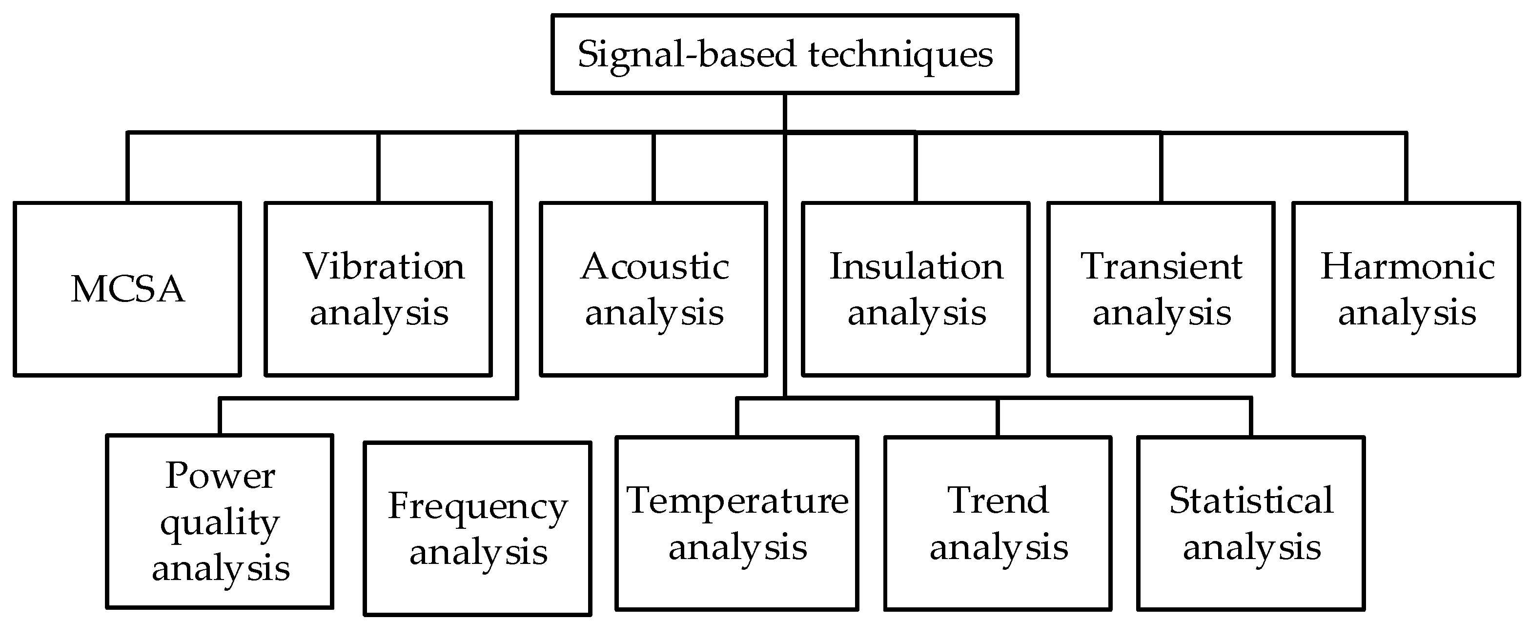
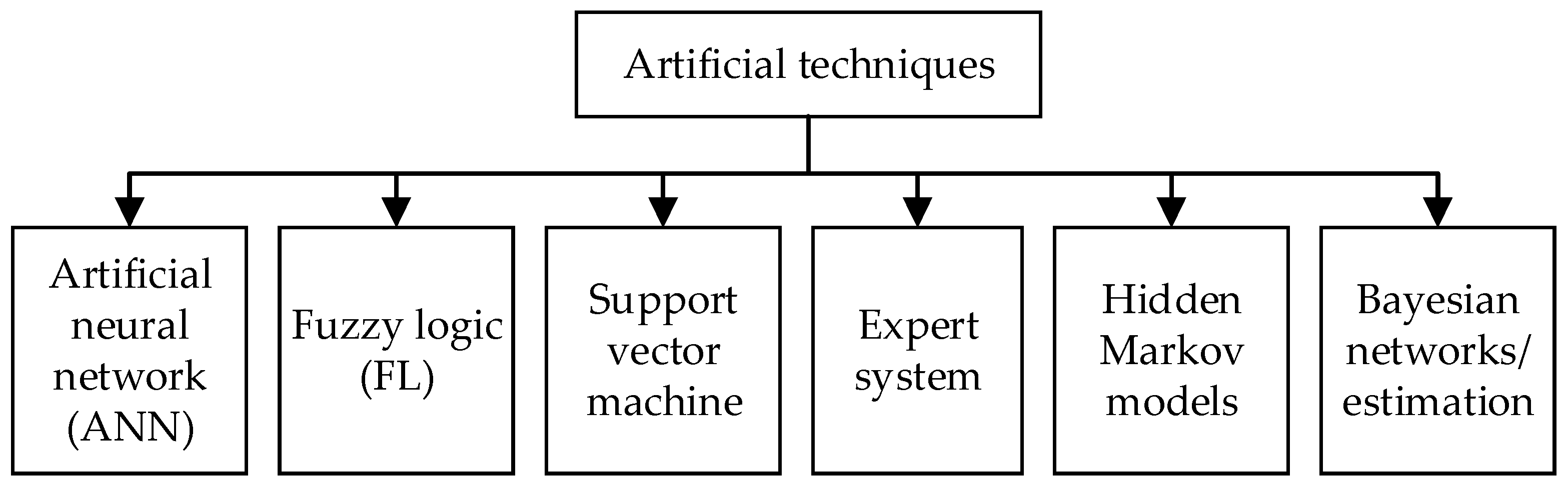
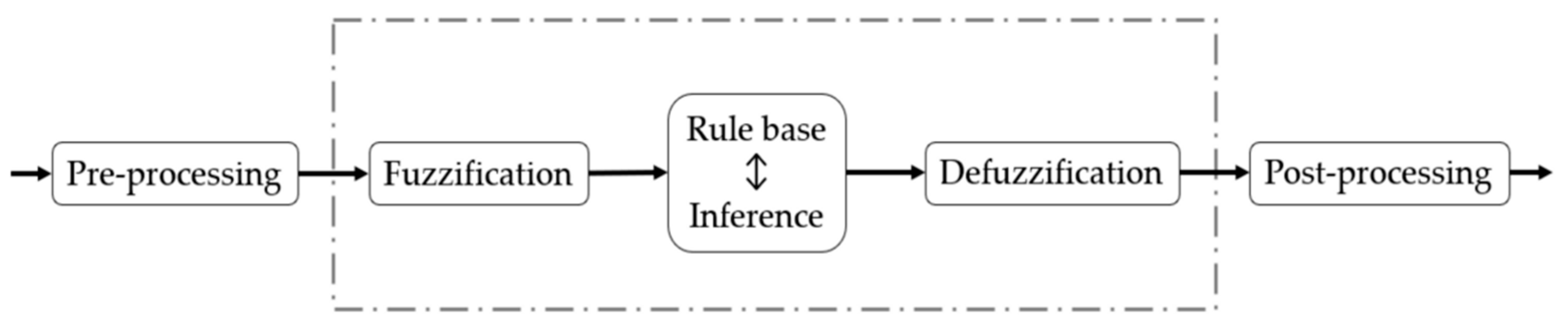