
Progress in Solid Oxide Fuel Cells with Hydrocarbon Fuels
by
 ,
,
Mohamad Fairus Rabuni
1,* ,
,
Tao Li
2,*,
Mohd Hafiz Dzarfan Othman
3,
Faidzul Hakim Adnan
1 and
Kang Li
4,* 1
Sustainable Process Engineering Centre (SPEC), Department of Chemical Engineering, Faculty of Engineering, Universiti Malaya, Kuala Lumpur 50603, Malaysia
2
MOE Key Laboratory of Energy Thermal Conversion & Control, School of Energy and Environment, Southeast University, Nanjing 211189, China
3
Advanced Membrane Technology Research Centre (AMTEC), Faculty of Chemical and Energy Engineering, Universiti Teknologi Malaysia (UTM), Skudai, Johor Bahru 81310, Malaysia
4
Barrer Centre, Department of Chemical Engineering, Imperial College London, Exhibition Road, London SW7 2AZ, UK
*
Authors to whom correspondence should be addressed.
Energies 2023, 16(17), 6404; https://0-doi-org.brum.beds.ac.uk/10.3390/en16176404
Submission received: 30 July 2023
/
Revised: 25 August 2023
/
Accepted: 2 September 2023
/
Published: 4 September 2023
(This article belongs to the Special Issue Applications of Nanomaterials in Clean Energy)
Abstract
:Solid oxide fuel cells (SOFCs)’ main advantage in fuel flexibility appears to be an interesting subject for further exploration. From the literature survey, direct utilisation of hydrocarbon as fuel for SOFCs has garnered attention with promising results reported. Various approaches, showcasing potential for using methane (CH4) and heavier hydrocarbons in SOFCs, have been described. The direct use of hydrocarbons can occur through either direct internal reforming or gradual internal reforming, with requisite precautionary measures to mitigate carbon formation. While the internal reforming process could proceed via steam reforming, dry reforming or partial oxidation, an exciting development in the direct use of pure hydrocarbons, seems to progress well. Further exploration aims to refine strategies, enhance efficiency and ensure the long-term stability and performance of hydrocarbon-fuelled SOFC systems. This review delves into the progress in this field, primarily over the past two decades, offering comprehensive insights. Regardless of fuel type, studies have largely concentrated on catalyst compositions, modifications and reaction conditions to achieve better conversion and selectivity. Finding suitable anode materials exhibiting excellent performance and robustness under demanding operating conditions, remains a hurdle. Alternatively, ongoing efforts are directed towards lowering working temperatures, enabling consideration of a wider range of materials with improved electrochemical performance.
1. Introduction
In recent years, interest has increased in developing a highly efficient, low-carbon and renewable energy conversion system, as greenhouse gases release from the conventional energy generation methods have become widely known to be harmful to the environment. The most common combustion of fossil fuels has long been used for energy generation, although it suffers from relatively low efficiency and contributes to environmental pollution. Thus, a more efficient and environmentally benign technique to produce energy is required. Fuel cell technology is an encouraging technique to generate energy by directly converting the chemical energy in fuel into electricity through electrochemical reaction. It is a practical application, promising a better, clean alternative source of energy. There are various types of fuel cells that can be characterised according to their particular materials, the charge being transported, their electrolyte and operating temperature. The reader is referred to several review papers for a more thorough description [1,2,3,4,5,6,7,8,9]. Among all types of fuel cell, solid oxide fuel cells (SOFCs) have attracted considerable attention because of two remarkable features related to their high operating temperature. First, it provides fuel flexibility, allowing the use of hydrocarbons, syngas and biofuels. Secondly, SOFCs generate a considerable amount of exhaust heat that may be used in combined heat and power systems (CHP) for even higher efficiency. Additionally, a major difference between an SOFC and its counterparts is the use of solid-state electrolyte. Its application can bypass common issues encountered with liquid electrolyte such as corrosion and electrode wetting [10]. SOFCs are also renowned for low emission of pollutants owing to their high conversion efficiency and could offer a quiet performance, since no moving parts or vibration are involved.
To date, several review papers are available in the literature with regards to the development of the SOFC anode materials and challenges for further development. For instance, McIntosh and Gorte have reviewed the progress of anode materials for SOFCs operating with hydrocarbons [11]. Sun and Stimming have also described and summarised various types of anode materials for hydrocarbon-fuelled SOFCs, the development of anode kinetics and reaction mechanisms, as well as the anode models and the economical processing methods for making anode [12]. Shi et al. have discussed the anodic reactions in hydrocarbon-fuelled SOFCs and strategies to improve anode performance and stability [13]. Shabri et al., on the other hand, have described the recent progress in the hydrocarbon-fuelled SOFC system which focused on the development of a metal–ceramic anode [14]. Their review highlighted the anode fabrication using either metal or metal alloy as cermet following the metal oxide reduction via hydrogen (H2) route. They presented a comprehensive discussion on the exploration of core components of the SOFC and delved into the most harmful degradation mechanisms they encountered, addressing poisoning, microstructural deformations and strains during operation [10]. More recent reviews on the progress in low-temperature (LT)-SOFC, highlighting the use of proton-conducting SOFCs with hydrocarbon fuels have been provided by Su and Hu [8] and Liu and Duan [9].
Worldwide interest in SOFCs has dramatically increased over the past decades as indicated by the tremendous growth in the number of patents applied as well as publications. Various leading institutions such as Colorado School of Mines, USA, University of Pennsylvania, USA, National Institute of Advanced Industrial Science and Technology (AIST), Japan, the University of St. Andrews, UK, are among those actively involved in this research field, as can be seen in Figure 1, which is the output of the result analysis using Scopus with keywords “hydrocarbon” and “solid oxide fuel cell” from year 1970 up until 2023. Nonetheless, several concerns regarding SOFC operation with hydrocarbons remain the focus of ongoing research quests. These include the rate-limiting electrochemical steps on anode, the nature of hydrocarbon reactions, the mechanisms for coking as well as the appropriate operating conditions by which stable coke-free operation can be maintained.
In this review, we present the progress in hydrocarbon-fuelled SOFCs, particularly those featuring Nickel (Ni)-based anodes and oxide-ion-conducting electrolyte by examining the research output on this subject primarily from the past 20 years. The following section covers inclusive information on different approaches available for direct utilisation of hydrocarbons. Section 1 presents the background of the SOFCs operation with hydrocarbon fuels, while Section 2 and Section 3 summarise information on an SOFC system operated by methane (CH4) and heavier hydrocarbons, respectively. As our emphasis is placed on the research with Ni-based anodes operated by hydrocarbons, therefore Section 2 and Section 3 largely report different existing strategies and results with respect to the electrochemical performance for works using Ni-based cells. Section 4 analyses the literature and tries to propose next research advances, mainly on the development of anode, stable operating conditions and microstructure tailoring of the cell. Ultimately, a sound understanding of the various approaches to hydrocarbon-fuelled SOFCs is crucial for better improvement and optimisation, aiming at accelerating the commercialisation of an SOFC system for a variety of applications.
1.1. Comparison between Oxide-Ion-Conducting SOFCs and Proton-Conducting SOFCs Fuelled by Hydrocarbons
Both oxide-conducting and proton-conducting SOFCs present distinct advantages and challenges when using hydrocarbon fuels. Generally, oxide-conducting SOFCs demonstrate superior efficiency due to their elevated operating temperatures and swift oxide ions transport [14]. This leads to improved energy conversion from hydrocarbon fuels, enhancing overall performance. By contrast, although proton-conducting SOFCs operate at lower temperatures where it provides the advantages in material stability and longevity [15], a trade-off arises in terms of efficiency compared to oxide-conducting SOFCs. In addition, oxide-conducting SOFCs prove more adept at accommodating a broad spectrum of hydrocarbon fuels, affording greater fuel flexibility, courtesy of their high operating temperature that facilitates efficient fuel reforming. On the contrary, proton-conducting SOFCs may necessitate specific reforming conditions to attain optimal performance. Additionally, both types of SOFCs face material selection challenges. Oxide-conducting SOFCs require materials capable of enduring high temperatures, potentially impacting long-term stability. In contrast, proton-conducting SOFCs benefit from lower operating temperatures yet encounter challenges linked to proton conductivity and slower kinetics.
Oxide-conducting SOFCs are typically more resilient against carbon formation when supplied with hydrocarbon fuels. Their higher operating temperatures and thermodynamic conditions enable efficient carbon management, reducing the risk of carbon deposition and ensuring prolonged cell performance. This distinction highlights the importance of considering the type of SOFC electrolyte when utilising hydrocarbon fuel to achieve clean and efficient energy conversion. When considering the use of hydrocarbons, oxide-conducting SOFCs appear as a compelling choice given by their higher efficiency, greater fuel flexibility and resistance to carbon deposition. These attributes align remarkably well with the imperatives of efficient energy conversion and sustainable use of hydrocarbon feedstocks. While proton-conducting SOFCs offer advantages in certain contexts, such as lower operating temperatures, their limitations in terms of efficiency and carbon management underscore the significance of oxide-conducting SOFCs for effectively harnessing the potential of hydrocarbon fuels in clean energy applications [16]. In addition, the materials employed in the fabrication of proton-conducting SOFCs are comparatively more expensive than those used for oxide-conducting SOFCs.
Recent work by Mojaver et al. entailed the simulation of a power generation system that utilizes an integrated CH4-fed SOFC and organic Rankine cycle (ORC), with validation carried out using available experimental data [17]. The model underwent thorough validation against the literature data. A comprehensive comparative assessment of the system’s performance was then undertaken, comparing the oxide-conducting SOFC with the proton-conducting SOFC. This analysis encompassed evaluations across energy, exergy, economic and environmental perspectives. The input variables taken into account were the current density and stack temperature. The findings pointed to the superiority of the oxide-conducting SOFC across various domains, i.e., energy, exergy, economic and environmental, when operating under their respective optimal conditions. It is noteworthy that this deduction is likely to hold consistently within the explored ranges of decision variables.
As the global energy landscape continues to progress, the better performance of oxide-conducting SOFCs with hydrocarbon fuels positions them as a frontrunner in the pursuit of a cleaner and more sustainable energy future.
1.2. Mode of Operations for Hydrocarbon SOFCs
The use of hydrocarbons from fossil fuel or renewable sources is desirable for energy generation as certain difficulties associated with hydrogen (H2) production, safety, storage and distribution have yet to be resolved [18,19,20]. With escalating demand and limited supply, hydrocarbons will become even more pricey, emphasising the importance of high conversion efficiency of energy generation devices such as SOFCs. While significant progress has been achieved in H2-fuelled SOFC studies, investigations continue into the potential use of hydrocarbons. Fuel flexibility is one attractive feature of SOFCs, as they may operate using hydrocarbon fuels, i.e., natural gas, biogas, etc., with less fuel processing compared to other fuel cell types [21].
For hydrocarbon-fuelled oxide ion-conducting SOFCs, there are several modes of operations including external fuel reforming prior entering the cell, internal reforming or directly feeding the pure hydrocarbon into the cell [22]. These approaches are represented in Figure 2, where Figure 2a shows the ideal operation with direct oxidation of the hydrocarbon fuels, and Figure 2b–d illustrate the reforming of hydrocarbon fuels either through external reforming, indirect internal reforming or direct internal reforming, respectively.
The reforming process transforms the hydrocarbon to simpler fuels, i.e., H2 and CO, which can then be used directly in a fuel cell. While CO may be considered as a contaminant in most low-temperature fuel, SOFCs can be operated by it. This helps to simplify the fuel process by excluding the purification step. Fuel reforming can be performed externally, using a separate fuel processor known as a reformer, or internally at the anode (Figure 2b). A variant of internal reforming is either to add a separate reforming catalyst within the anode compartment (indirect internal reforming represented by Figure 2c) or directly on the anode (direct internal reforming as shown in Figure 2d) [23]. In a system with indirect internal reforming, reforming catalyst was integrated within the SOFC at the entry point of the hydrocarbons in anodic compartment. However, there could be a significant gradient between the rates of endothermic and exothermic reactions. This would cause a consequential decrease in local temperature at the upstream of anodic compartment that could lead to mechanical failure resulting from thermally induced stresses [24]. Alternatively, direct internal reforming works by the principle of direct feed of SOFCs using a mixture of fuel and reforming agents. This mode in overall offers lower operational cost, reduces the system complexity and necessitates less maintenance thanks to the relinquishment of external reformer, making the system more desirable.
Another considerable interest has been given to a process whereby hydrocarbon-rich fuel is directly fed into the anode compartment (i.e., without the reforming agents). Since external reforming increases complexity and cost to the system, direct feed of hydrocarbon-rich fuel offers substantial advantages. This approach is poised to attain higher energy conversion efficiency in addition to the least fuel processing of the system. The direct use of hydrocarbons for SOFCs is, in principle, possible and attractive thanks to the particular prospect of gradual internal reforming of hydrocarbons. Conditionally, the anode material needs to satisfy several ideal criteria, including high catalytic activity for fuel oxidation and excellent ionic and electronic conductivity. At high SOFC working temperatures, either the direct electrochemical oxidation or the internal reforming/partial oxidation of the hydrocarbons becomes kinetically favourable. Nevertheless, these different modes of operation mentioned above have both advantages and disadvantages. Research into each method is still continuing to gain further understanding of the reaction mechanism, better cell performance and eventually helps to accelerate commercialisation. Overall, a different approach when dealing with an SOFC with Ni-based anode when operated with hydrocarbon fuels must be carefully considered with the major aim to avoid carbon formation to ensure stable performance.
1.3. Direct Hydrocarbon Utilisation
In theory, the use of hydrocarbons directly may improve the overall efficiency of a system. It is, however, worth mentioning that the understanding of “direct use of hydrocarbon fuels” by electrochemical means is still ambiguous. Compared to the well-understood chemical oxidation of hydrocarbons (i.e., hydrogenation and hydrogenolysis, partial oxidation and complete oxidation), the electrochemical oxidation of hydrocarbons is less well understood. In the literature, several terms have been introduced to designate “direct use of hydrocarbon fuels” such as direct utilisation, direct conversion or direct oxidation. This might lead to confusion and misinterpretation of precise definitions.
Mogensen and Kammer defined direct conversion of a hydrocarbon during SOFC operation as the “conversion in the SOFC without pre-mixing the fuel gas with steam or carbon dioxide (CO2) and without processing the fuel before it enters the cell stack” [19]. This implies that the reaction is either through direct electrochemical oxidation or electrochemical oxidation of cracking products with the open circuit voltage (OCV) equals to the Nernst potential. Thus, all steps in the reaction of hydrocarbon conversion must be electrochemical in nature and any reaction pathways that encompass hydrocarbon cracking and electrochemical oxidation of the cracked products are not considered as direct oxidation. In our view, to interpret “direct use of hydrocarbon fuels” to be equivalent to “direct oxidation” is fairly rigid and unfeasible for actual application and, thus, less suitable.
Besides, it has been described that the direct electrochemical oxidation of hydrocarbons is unlikely to occur in one step [25,26]. Gas chromatography (GC) analysis has shown that partial oxidation reactions are dominant for some oxide anodes [27]. For that reason, to define “direct use of hydrocarbons” to be similar to “direct oxidation” seems impractical. McIntosh and Gorte instead suggested a broader definition describing the direct use of hydrocarbon fuels in an SOFC using the term “direct hydrocarbon utilisation” [20]. By this meaning, besides a process wherein a dry (i.e., pure) fuel is fed into the system, it also takes in humidified fuels (approximately 3 vol.% H2O), regardless of the exact reaction steps [20]. For practical reasons, such a definition is used throughout this review.
It is expected that operations with hydrocarbons as fuel will be much more complex than those using the simpler operating principle of a H2-fuelled system. As shown in Figure 3, there is a possibility of different parallel pathways during direct hydrocarbon use in SOFC, each with various individual steps. The ideal reaction for a hydrocarbon-fuelled SOFC is direct oxidation (Figure 2a), in which oxide ions (O2−) from the cathode travel through the electrolyte and oxidise the hydrocarbon at the anode triple phase boundary (TPB), a region at which the three components, oxygen ions, electrons and fuels, meet. This ideal and straightforward reaction represented by the following equation releases the most energy since no endothermic processes are involved:
However, this requires effective catalysts and careful control of operating conditions. It may also involve multiple steps, along with side reactions such as pyrolysis and oligomerisation. Since side reactions are inherent during the actual operation, the electrochemical reactions for hydrocarbon fuel may proceed either through (1) oxidation of cracked carbon and hydrogen, (2) oxidation of an oxygenated compound or (3) oxidation of the intermediates produced from free radical reactions.
Although an SOFC offers the advantage of fuel flexibility, its choice is still limited by the affinity of the hydrocarbons to foul the regularly used Ni–cermet anode surface. This fouling which is caused by the carbon formation has become a major impediment that needs to be solved for stable SOFC operation. Unless a suitable catalyst is present to realise direct oxidation of hydrocarbons to minimise this problem, hydrocarbons must be reformed prior to the electrochemical reactions. Another concern is catalyst poisoning by contaminants such as hydrogen sulphide (H2S), which could poison the catalyst containing anodes. There have been several comprehensive reviews about this topic [28,29], where interested readers can refer to and it is worth mentioning that it is beyond the scope of this review.
1.4. Carbon Formation
An intrinsic problem in SOFC operation when using hydrocarbons as fuel is the formation of carbon through undesired side reactions. It has been reported that the deposition of carbon disrupts the performance of an SOFC, particularly one with Ni-based anodes, as Ni itself is an excellent catalyst for C-C and C-H bond breakage [30]. At high temperatures, hydrocarbon reactions may occur not only on the anode surfaces but also at the interconnect plates and the tubes connecting to the anode compartment. It could also happen in the gas phase via free-radical cracking and polymerisation, forming tar. This deposited carbon can cause pore blockage, obstruct reforming reactions through catalyst particle encapsulation and increase transport resistance to gases trying to reach the TPB, hence lowering the overall system performance.
If this technology is to be practical and economical, understanding the mechanism of carbon formation is indispensable. There are two mechanisms that have been generally reported: first, heterogeneous reaction on catalyst surfaces, producing carbon nanowires or nanofibres, and secondly, homogeneous reaction in the gas phase, forming soot capable of being ubiquitously deposited at the anode. This soot or pyrolytic carbon may cover and deactivate the catalyst. Thorough explanations of these mechanisms have been given by other researchers [19,20,22,31].
There are several factors that affect the degree of carbon formation including reforming agent to carbon (i.e., steam/C or CO2/C) ratio, operating conditions and catalyst material. Keeping the fuel within an equilibrium noncoking condition is one way for maintaining stable coke-free operation [20]. This region of stability for hydrocarbon fuels could be mapped based on thermodynamic calculations and would be a useful reference for avoiding severe effects of carbon deposition. Accordingly, selecting appropriate operating conditions (e.g., temperature, pressure and current density) may minimise the severity of the problem, if not totally eliminate it. As can be seen in Figure 4, the composition triangle for C-O-H shows carbon formation limits at 1000 °C, while 800 °C is close to 1:1 for a C/O ratio but displays a considerable discrepancy at a lower temperature. The addition of an ample amount of reforming agent (H2O, CO2 or O2) aids in diminishing the formation of carbon.
Appropriate choice of catalytic material for reforming steps is another important issue to ensure stable system performance. The material has a substantial role as it must be efficient in preventing carbon formation and steady for long-term usage while remaining cost-effective. It is also worth mentioning that several studies reported that the actual ratio of reforming agent to carbon for efficiently suppressing coke formation considerably differs from that expected by thermodynamic calculations. This large discrepancy can be associated with the fact that thermodynamic calculations only provide insight into the predicted equilibrium conditions and do not consider the influence of reaction kinetics [33]. In this light, numerous researchers have examined the reaction kinetics of carbon formation, in search of optimum operating conditions and better materials for the anode [34].
Despite the challenges regarding carbon formation, direct hydrocarbon-fuelled SOFCs are interesting in terms of simplification of fuel processing and the overall energy costs may be substantially reduced. Works on this operation mode have been actively researched for the past two decades, whereby several approaches, including internal reforming or even direct feeding of the fuel into the cell have been studied. There does exist a major difference between the operation with methane (CH4) and other higher molecular weight hydrocarbons (heavier hydrocarbons) as fuel. Theoretically, the molecule of CH4 is simpler and relatively more stable and thus could be used directly (in undiluted form) with less tendency towards coking. Heavier hydrocarbons (i.e., other than methane), on the contrary, incline to cause a considerable coke or tar deposition on the anode or fuel-compartment surfaces, even when mixed with steam (steam reforming) or carbon dioxide (dry reforming). Therefore, the strategy to deal with heavier hydrocarbons may be differ from that of CH4-fuelled system. These processes are further elaborated upon in subsequent sections.
2. Methane-Fuelled SOFCs
Methane (CH4), as an abundant resource and the main element of natural gas, is predicted to become the major hydrocarbon feedstock in future [35]. Natural gas is a fossil fuel that is much cleaner than coal and oil due to its higher hydrogen (H) to carbon (C) ratios in its molecular composition and contains a trivial amount of nitrogen (N) and sulphur (S) impurities. Other than that, CH4 is also the main constituent in biogas with CO as the remainder. The biogas is produced from anaerobic fermentation of various organic matters such as manure, wastewater sludge, municipal solid waste or another decomposable feedstock. Accordingly, CH4 could be viewed as a promising renewable energy resource which is important for energy generation.
To date, most studies conducted on hydrocarbon utilisation in SOFCs have used CH4 as fuel (Table 1). This is largely due to a chemical profile throughout its electrochemical process that is simpler than that of heavier hydrocarbons. Ni–cermets continue to be the most frequently applied materials for an SOFC anode. However, as previously described, they are prone to coking, restricting their use in hydrocarbon-fuelled system. As noted earlier, this review emphasis on the research of SOFCs with Ni-based anodes fuelled by hydrocarbons. Further modifications on the Ni–cermets properties are essential along with several other strategies have been proposed in the literature to resolve such issues. Various ways to use CH4 as fuel are discussed in the following sections which includes internal reforming mode either by steam, CO2 or partial oxidation, as well as direct utilisation. Table 1 lists the methane-fuelled SOFCs, mainly those with Ni-based anodes and oxide-ion-conducting electrolyte.
2.1. Internal Reforming
Thermodynamic means are one approach to controlling the formation of carbon during the operation of SOFCs with hydrocarbon fuels. This could be performed by introducing reforming agents such as steam or other oxygen-containing oxidants (CO2 or O2) together with the fuels into the fuel cell system. The internal reforming is a straightforward process by simply mixing hydrocarbon with reforming agents at a certain ratio to transform into simpler fuels such as hydrogen (H2) and carbon monoxide (CO) in situ. Internal reforming of CH4 and natural gas in SOFCs have been studied, either with or without partial pre-reforming [66,67]. However, operation with natural gas is slightly different from using pure CH4 as some heavier hydrocarbons contained in the natural gas are likely to cause coking. Thus, the additional pre-reforming step is often required. An internal reforming process of pure CH4, instead, could be directly performed either through steam reforming, dry (CO2) reforming or partial oxidation. During SOFC operation, one major virtue is that heat is generated in the cell by electrochemical reactions, and this ohmic heating could be directly used for the endothermic reforming reaction [67].
Steam reforming, dry reforming and partial oxidation are expressed in Equations (2)–(4), respectively [68]. All of these reactions yield syngas with different CO/H2 ratios: 1:1, 1:2 and 1:3 for dry, partial oxidation and steam reforming process, respectively.
where is the reaction standard enthalpy at 298 K.
These different means for internal reforming are summarised in Table 2. Detailed information about these processes is discussed in the following sections.
2.1.1. Internal Steam Reforming
A study on SOFC operation with hydrocarbons with steam as an input has been conducted as early as in 1962 [69]. Reforming the fuel internally may help to diminish the energy required for water gasification and lead to process simplification as the external reformer can be excluded. It has been reported that the effectiveness of internal reforming to be greater than that of external reforming in the same SOFC system [70]. This process typically applies a steam-to-carbon (S/C) ratio of higher than two to suppress carbon deposition. More interestingly, in the presence of generated water from the electrochemical reaction at the anode, the reforming process could occur even at a lower S/C ratio. Therefore, the supply of CH4 mixed with a small amount of steam directly to the system inlet is attractive for process simplification.
The operating temperature and S/C ratio have major influences on the degree of coke formation. A CH4 internal reforming study using electrolyte-supported single cells with different types of anodes, i.e., Ni-YSZ and Ni-GDC (gadolinium-doped ceria), were performed at various S/C ratios, from 0 to 3 [71]. At 950 °C, virtually no discrepancy in the reforming activities of both anodes was observed. However, at a lower temperature of 800 °C, the conversion rate greatly relies on the anode material with a higher CH4 conversion obtained using a cell with Ni-GDC anode. A similar observation of catalytic activity for the reforming reactions has also been reported elsewhere [72]. It is often thought that a higher S/C ratio would lead to a more efficient reforming process as abundant steam would assist in gasifying deposited carbon and prevent carbon buildup. However, this may not always be the case, as a degradation of a Ni-YSZ anode has been discovered in a system operated with a S/C ratio of 3 [55]. The excess steam was found to oxidise nickel catalyst locally at a vicinity of the interface between electrolyte and anode. More important, excessive steam compromises power generation efficiency by diluting the fuel. Another drawback is that the endothermic nature of steam reforming reaction could cause local cooling where the resultant steep thermal gradient might mechanically damage the cell stack [73]. Although a lower S/C ratio is preferred, carbon may be formed at a ratio of less than one in the equilibrium causing poor electrochemical performance [74]. This is attributable to the deactivation of anode catalysts and the inhibition of fuel diffusion. Therefore, the S/C ratio should be carefully chosen depending on the type of anode materials and the operating conditions.
The improvement on the reforming process could be expected through the addition of catalytic materials into the Ni-based anodes. Incorporation of these catalysts as part of the anode may not only prohibit carbon deposition but also increase the electrochemical performance, as less water for reforming is needed. A noticeable reduction in carbon formation is observed on the modified Ni-YSZ cermets with small quantities (~1 wt%) of molybdenum (Mo) during CH4 reforming, despite having a slight effect on the reforming activity and cell performance [73]. In contrast, another study employing a cell with copper (Cu)-based anodes reported an opposing outcome [75]. The deposition of MoOx has been believed to some extent to shield the electrocatalytic sites, reducing anode performance and thus being inappropriate in inhibiting coke formation. More research is, therefore, necessary to elucidate such discrepancies.
Takeguchi et al. performed a series of systematic studies on a modified Ni-YSZ anode for a system fuelled by CH4 with a S/C ratio set at 2 [76,77]. Different alkaline earth oxides, such as calcium oxide (CaO), strontium oxide (SrO), ceria (CeO2) and magnesium oxide (MgO) have been incorporated to the conventional Ni-YSZ anodes [76]. With the first three oxides, carbon deposition was suppressed, while MgO incorporation increased the rate of carbon deposition and reduced the steam reforming activity. A high content of SrO (~2 wt%) in the anode, however, led to poorer CH4 conversion. Further improvement in the reforming activity could be achieved with the addition of precious metals such as ruthenium (Ru) and platinum (Pt) that helps to increase the anode resistance towards coke formation [77]. In another work, CH4 steam reforming was conducted on a cell with dual-layer anode, Ni0.5Cu0.5Fe2O4 and Gd0.1Ce0.9O1.95−δ (NCF-GDC) composite, screen printed onto Ni-YSZ [78]. No significant signs of coking were detected during the operation using CH4-H2O (7 mol%) mixture as fuel at 800 °C and 0.20 A cm−2. On the contrary, poor electrochemical performance was observed with fuel mixture containing an excessive amount of steam (20 mol% H2O) corresponding to fuel dilution.
Aiming at lowering SOFC operating temperature to less than 600 °C, Suzuki and co-workers have introduced a functional layer made of pure ceria, placed on top of the conventional anode surface [52]. Such a layer was beneficial in improving the maximum power density to 0.45 W cm−2 from 0.35 W cm−2 for a cell without such a layer when operated at 554 °C fuelled with CH4 and steam mixture with nitrogen (CH4/H2O/N2 = 15/60/25 mL min−1). This additional layer allows reforming of CH4 into H2 and CO, which later being electrochemically oxidised within the anode–electrolyte TPB region.
Notwithstanding their practicality and effectiveness during SOFC operation, there are several concerns with regards to internal steam reforming that must be addressed. The endothermic nature of the process assists in cooling the stack, and it may be difficult to retain a uniform temperature and H2 content throughout the stack. Severe cooling may take place near the fuel inlet if the reforming reaction is too rapid, causing a very large temperature gradient along the stack [67,79]. This shortcoming may give rise to inhomogeneous temperature distributions which is detrimental to the mechanical properties of the cermet anode. One potential solution is to ensure an optimal operation wherein the reforming reaction and the electrochemical reactions progress at similar rates [80].
2.1.2. Internal Dry Reforming
Steam can be replaced by carbon dioxide (CO2) as a reforming agent, a process known as dry reforming [81]. Other than being applied for producing synthesis gas (syngas) in the presence of a suitable catalyst, this technique appears to be a potential approach to mitigating greenhouse gases [82]. It is attractive from an industrial standpoint, as the resulting syngas has a low H2 to CO ratio, suitable for Fischer–Tropsch reactions, a process to yield liquid hydrocarbons. This reforming system is also practical, given that both CH4 and CO2 are abundantly available and inexpensive. Despite its benefits, the reaction is very endothermic (), requiring an extensive amount of energy. Moreover, reforming catalysts, which are often Ni-based, are susceptible to deactivation due to coke deposition. Hence, these issues need to be first addressed, and one way of doing it is by developing catalysts that have excellent activity and high resistance against coking [35,83]. In addition to Ni-based catalysts [84,85], other types of catalysts have been explored for this reaction, such as with precious metals, e.g., iridium (Ir), Rh, Ru, Pd, Pt and others [86,87,88]. These materials were reported to have an encouraging catalytic performance with respect to activity and selectivity to syngas formation. Precious metals are renowned for their outstanding coking resistance, yet do not seem to be practical for large-scale uses for economic reasons.
Alternatively, ceria (CeO2) doped with materials such as zirconium (Zr), praseodymium (Pr) and niobium (Nb) were mixed with Ni and have been applied as anodes for an SOFC operated on CH4-CO2 mixture [84]. The anodes were prepared by a hydrothermal method with a Ni content (14 vol.%), much lower than that of typical SOFC anodes (i.e., 30 vol.%). Among these, an anode containing Zr showed the lowest Ni crystallite size leading to a high initial activity on CH4 dry reforming at 800 °C. Overall, the Ni-CePr catalyst had the least carbon formation associated with the greater oxygen conductivity of CePr support that facilitates carbon removal.
Apart from material selection, the influence of the microstructure of the anode on the catalytic properties under dry reforming has been investigated [89]. Two types of Ni-cermet anodes (i.e., Ni-YSZ and Ni-GDC) with different microstructure upon a sintering process at different temperature were compared. By determining the specific surface area of these anodes and through morphological observations, it was established that anode microstructure has significant impacts on the catalytic properties. The specific surface area of the anode considerably affected the CH4 conversion rate whereby the cell with a Ni-YSZ anode sintered at 1200 °C which has a larger surface area gave a higher conversion rate. Another simulation study proposed an innovative SOFC configuration based on the coupling of the fuel cell and CH4 dry reforming method [82]. Using Aspen Plus, the performance between the more common steam-methane-reforming (SMR)-SOFC and dry-methane-reforming (DMR)-SOFC processes was compared, where the efficiency was much better for the latter configuration with an increment of 6.4%. In another work, the prospect of co-generating electricity and CO-concentrated syngas has been demonstrated [90]. A functional layer made of a Ni0.8Co0.2–La0.2Ce0.8O1.9 (NiCo–LDC) composite was added onto the anode support, and the system was fed by a CH4–CO2 stream. Such a layer efficiently catalysed dry reforming in situ with CO2 conversion reaching 91.5% at 700 °C and remaining stable for 100 h. Moreover, CH4 was effectively converted through electrochemical oxidation, producing CO-concentrated syngas in the anode effluent. At 700 °C, maximum power density surpassed 0.91 W cm−2 with a low polarisation resistance of 0.121 Ω cm2. More interestingly, this system is thermally self-sufficient, as the heat released by the H2 electrochemical oxidation compensates for the requirements of the endothermic dry reforming reaction.
In addition, the performance and degradation mechanisms of a Ni-based anode-supported SOFC operating at ∼800 °C on the direct internal reforming of dry CH4–CO2 mixtures have been studied by Lanzini et al. [91]. Internal reforming with CO2 has been shown to be effective in reducing carbon formation with a great prospect to cogenerate syngas and concurrently treat greenhouse gases, although, similar to steam reforming, the excessive ratio between CO2 and CH4 would dilute the fuel, affecting the H2 yield and the overall efficiency of the system [92]. Accordingly, optimal operating conditions are of great importance in order to achieve decent performance.
2.1.3. Partial Oxidation
Partial oxidation (POx) involves a chemical reaction between the hydrocarbon fuel and oxygen generally from the air, in a substoichiometric ratio, thus the term “partial oxidation”. This alternate approach to fuel reforming allows stable operation, where electricity and valuable chemical products such as syngas are coproduced [93,94]. However, considerable energy loss during oxidation of the hydrocarbon has caused the system with POx to be less energy efficient than with steam reforming even without heat recovery [95]. Nevertheless, the simplicity of the process makes POx attractive, i.e., for auxiliary power unit (APU) application [96].
Asano et al. applied a cell composed of Pt-BaCe0.8Y0.2O3−δ-Au operated under POx [97]. Their system did not require a separate supply of fuel and oxidant gases, as the two electrodes (Pt and Au) were exposed to the same mixture of CH4 and air. Pt functions as a fuel electrode catalysing the partial oxidation of CH4 to form H2 and CO, whereas Au acted as an oxygen electrode. Electrochemical reduction of oxygen takes place on discharging the cell. In a uniform atmosphere, the cell produced 0.17 W cm−2 at 950 °C.
An attempt to decrease the reforming temperature has been proposed by using catalytic partial oxidation (CPOx), reducing temperatures from about 1200 °C to between 800 and 900 °C, using Ni as a catalyst. Many articles related to catalysts for POx of CH4 could be referred [98,99,100]. The state-of-the-art anode is mainly of Ni cermets, as Ni itself acts as a catalyst for the partial oxidation and at the same time functions as an electronic conductor. Nevertheless, similar to the steam and dry reforming, the use of modified Ni catalysts with elements having multiple oxidation states (e.g., Pt and Rh) for a POx process led to a better performance than using pure Ni. Employment of these catalysts led to higher reaction temperature, better fuel conversion and faster O2 conversion [101]. A microtubular (MT)-SOFC consisting of an anode coated with added catalytic material coupled with a POx process demonstrated stable operation for over 1000 h [102]. Additionally, Majewski and Dhir reported steady power generation through direct feeding of CH4 using a microtubular cell with a reforming catalyst placed at the cell inlet [103]. The catalyst in a honeycomb structure gave better fuel conversion with a constant rate of H2 production and trivial coke deposition. They also investigated the temperature distribution along an MT-SOFC [60]. Such studies showed that not only catalyst structure could affect the SOFC performance, but the positioning of the catalyst also plays a major role in ensuring the stable operation.
A system fed with a CH4:O2 ratio of 2 showed negligible carbon formation, and Ni oxidation was inhibited [104]. Cells with different anodes, Ni-YSZ or Ni-GDC, were compared, whereby in all cases, the latter had superior electrochemical performance. The maximum power densities achieved with a Ni-GDC anode were 1.35 W cm−2 and 0.74 W cm−2 at 650 °C and 550 °C, respectively. For Ni-GDC anode, the chemical analyses indicated that oxidation of Ni is inhibited which is due to the oxygen exchange ability of GDC. The use of various reforming agents (H2O, CO2 or O2) to reform CH4 was systematically studied using a cell with a Ni-ScSZ (scandia stabilised zirconia) anode and a functional layer at 850 °C [105]. It was observed that the maximum power densities of the system operated on all three gas mixtures increased initially as the ratios of CH4-to-reforming agents increased but inevitably reduced afterwards. The maximum power densities were acquired at CH4: H2O/CO2/O2 ratios of 2:1, 4:1 and 8:1, respectively. Too much reforming agents result in large quantities of unconverted H2O, CO2 and O2 given by the poor catalytic activity of the anode. These unconverted gases diluted the fuels, reducing H2/CO concentration. Likewise, a high CH4-to-reforming-agent ratio also leads to decreased H2 and CO concentrations in the fuel gas because of the low amount of these gases are formed.
Another mode of operation which combines POx and reforming either with steam or CO2 could as well be applied for CH4–fuelled SOFCs. This strategy, so-called autothermal reforming (ATR), has the benefits of both processes; it is more flexible than steam reforming on start-up time and has higher efficiency than POx. By carefully controlling the ratio of steam to hydrocarbon fuel and the amount of oxygen supplied, an ATR system can achieve a self-sustaining process. The heat generated by the POx reaction provides the necessary energy for the endothermic steam reforming reaction. The resulting gas mixture, consisting of hydrogen, carbon monoxide and water vapor, is then used as a fuel for the SOFC. The effects of CO2 and air addition for a system fed by CH4 have also been studied through modelling [106], in which the stability, which was evaluated by monitoring the fluctuations in voltage at constant current density, was greatly influenced by carbon deposition. At 800 °C, maximum power densities of more than 1 W cm−2 could be achieved with fuel streams of 75% CH4–25% CO2 [106]. Mixing CH4 with air as the gas inlet has also been found to increase the stability of the system. Another steady operation for 100 h has been demonstrated for a system fuelled with a 1:5 air-to-CH4 ratio [107].
Some works from the literature indicate that the long-term use of Ni-based cermet anodes (i.e., Ni-YSZ and Ni-GDC) might not be appropriate for SOFCs fuelled by CH4 even with internal reforming or partial oxidation. Nevertheless, suitable modification of this type of anode is always essential by incorporating suitable catalytic materials that could lower the activity for carbon formation. In addition, the optimum ratio between the reforming agent and CH4 is crucial to both evade fuel dilution and suppress formation of carbon.
2.2. Direct Methane Utilisation
Here, we define “direct utilisation” of methane (CH4) as a process where pure or nearly pure CH4 (i.e., mix with about 3% of H2O, CO2 or O2) is introduced to the system, analogous to the definition adopted in a previous review [40]. This approach is possible even if the fuel does not undergo the external reforming process. A long-term steady power generation was demonstrated by a system operated with humidified CH4 (3% H2O) at 1000 °C using Ni-ScSZ as anode [108]. It has also been described that during direct utilisation, gradual internal reforming (GIR) may occur by using electrochemically generated H2O and CO2 [109]. This GIR concept is based on a self-sustained operation in which the water produced from the electrochemical oxidation of H2 reacts in the in situ steam reforming reaction of the hydrocarbon fuel. Provided appropriate conditions are applied, direct SOFC operation with CH4 using the conventional Ni-YSZ anode has also been shown to be possible [42]. Despite the encouraging performance of this Ni cermet, it is susceptible to coking, as Ni catalyses the hydrocarbon cracking. Several strategies have been proposed to inhibit carbon formation, especially when using Ni-based anodes [110]. These may be categorised into the following: stable operating conditions, modification of a Ni-based anode through surface decoration or incorporation of additional catalyst materials and application of barrier or catalytic layer, placed onto the anode. Alternatively, the use of non-Ni anodes has been actively researched as well.
2.2.1. Stable Operating Conditions
Several studies have reported the feasibility of operating a stable SOFC without coking through direct utilisation of CH4 under controlled working conditions [42,111,112,113]. There are two approaches involving either operating at a high current density or applying a low working temperature, typically less than 700 °C. The latter could effectively hinder CH4 cracking, whereas high current density means there are more reaction products (CO2 and H2O) that could help to facilitate fuel reforming [73]. The noncoking operation can still be achieved even at higher temperatures if appropriate current density is applied [43]. Otherwise, coking is expected to occur, leading to rapid cell failure. During the SOFC operation, the primary electrochemical reaction taking place in anodic compartment involves CH4 reforming to produce H2O (steam) which is subsequently oxidised into H2 [43]. The resulting steam assists in removing carbon, preventing coking at high applied current densities.
The direct CH4 operation of Ni-YSZ anode-supported cell resulted in power densities of 0.96 W cm−2 at 800 °C has been reported [42]. By assuming partial oxidation of solid carbon as part of the anodic reactions, the measured OCV value was consistent with theoretical values. A two-step reaction mechanism was proposed involving, firstly, CH4 cracking followed by the electrochemical oxidation of the resulting solid carbon. A significant buildup of carbon on the anode was suppressed by retaining an appropriate current flowing through the cell. Lin et al. studied the stability of a humidified CH4-fuelled cell at different current densities and temperatures [43]. They observed that for operation at 650 and 700 °C, a minimum current density of around 0.1 A cm−2 was necessary to retain stable operation. At higher operating temperatures, larger critical current density is needed, ranging from 0.8 to 1.2 A cm−2 and 1.4 to 1.8 A cm−2 for systems run at 750 and 800 °C, respectively. These results showed that the oxygen ions (O2−) flux, conducted through the electrolyte, was in part accountable for hindering carbon formation and allowing steady operation.
Another research explained that a sufficient local oxygen partial pressure originated from the pumping of oxygen ions from the cathode side could as well impede the hydrocarbon cracking [114]. This “self-decoking” phenomenon has been observed in a system with a Ni-CGO anode (3:5 by weight) where the pumped oxygen ions could electrochemically remove carbonaceous deposits. A higher CH4 utilisation rate was associated with an increase in CO selectivity. Jiao et al. showed the possibility of continuous power output in a system with a Ni-YSZ anode using pure CH4. This could be achieved by intermittent supply of CH4, whereby fuel supply and consumption play a substantial role in controlling the carbon deposition and its utilisation [115]. This alternative operating mode is feasible in enhancing the stability of direct methane SOFCs; however, prolonged duration of such an operation must be investigated to verify its long-term stability.
2.2.2. Anode Surface Decoration or Incorporation of Additional Materials
Introducing another material with high ionic conductivity and excellent catalytic properties (e.g., metals or oxides) into the Ni cermet anode is another way for system optimisation. This may be realised through Ni alloying with other metals or by surface modification via various techniques including wet impregnation, electrochemical deposition (electroplating) and microwave irradiation processes. Several researchers have ascertained that alloying Ni with another element could give better carbon tolerance. This is due to the reduction in the activity of Ni when it is alloyed with another metal that has lesser catalytic activity for cracking or for activation of C-H bonds. For instance, the alloy of Ni and copper (Cu) is anticipated to improve the stability of the anode during SOFC operation with hydrocarbons by suppressing carbon formation. Copper is known to be catalytically inactive towards hydrocarbon cracking reactions but works excellently as a current collector. A cell with Ni-Cu-YSZ anodes supplied with CH4 showed the presence of carbon deposited on such alloys surface, whereby the carbon deposition was reduced with the increasing amount of Cu [39]. Similarly, a cell made of Ni-Cu-GDC [116] presented improved performance with minor carbon deposition after long-term operation with dry CH4 at 750 °C. Furthermore, using Cu-Ni-samaria-doped ceria (SDC) anode-supported cell, the maximum power density of 0.317 W cm−2 was achieved at 600 °C [117]. While losing 60% of power density after 7 h of operation in dry CH4 with bare Ni, only 7% or 2% losses were measured after 12 h when Cu was doped into the cermet or added as an interlayer, respectively. The poor performance with a pure Ni anode is mainly due to the agglomeration of Ni particles and carbon deposition.
A nanostructured Cu-Ni-CeO2-YSZ anode (i.e., Cu-Ni-CeO2 impregnated into porous YSZ) has been employed which presents higher resistance to carbon deposition than the conventional Ni-based anode [118]. To assess the resilience of the Cu-Ni-CeO2-impregnated YSZ anode against coking, different types of anodes were prepared, including a blank porous YSZ matrix, Ni-impregnated YSZ and Cu-Ni-CeO2-impregnated YSZ. The loadings of both Ni and Cu-Ni-CeO2 were controlled at 40%. The results revealed a significant formation of carbon in the Ni-impregnated YSZ sample, while a reduced amount of black carbon was practical in the Cu-Ni-CeO2-impregnated YSZ sample, and no noticeable carbon deposition occurred in the porous YSZ sample. The nanostructured anode with a composition of Cu0.5Ni0.5 alloy had the best performance. Hence, the content of added metal, in this case, Cu plays a significant role in suppressing problems with coking. A contradictory outcome was reported, whereby the Cu−Ni alloys were found to be unstable in the presence of hydrocarbons, depending strongly on pre-treatment conditions [119]. Thus, more research should be performed to further investigate the suitability of Cu-Ni alloy as an anode for direct CH4 utilisation.
Another progress was realised using a Sn-modified Ni-based anode, whereby Sn doped with nanosized Ni and GDC were conjugated on a core GDC nanocomposite anode [120]. Operation with dry CH4 produced a power density of 0.93 W cm−2 and retained stable operation at 650 °C for over 40 h. Similarly, Yang et al. also used a Sn-modified Ni-based anode SOFC [121], in which a steady operation with humidified CH4 is achieved in a temperature range of 700–800 °C, using a cell with an Ni-SDC anode containing additional 1 wt% Sn into the porous anode.
Introducing alkaline earth oxide materials to the Ni-cermet anode is another route to reduce carbon accumulation. Theoretically, basic oxides can increase coking resistance through stimulating the reaction of steam or CO2 with the solid carbon. Asamoto et al. were among the first to study the effects of adding different alkaline earth metal oxides such as MgO, CaO, SrO and BaO to a Ni-SDC anode for direct oxidation of CH4 [122]. It was found that the addition of these materials leads to lower maximum power densities compared to the bare Ni-SDC. Nevertheless, only Ni-CaO-SDC showed viable stability for 24 h operation, as indicated by minor changes in the terminal voltage.
Using BaO as part of the anode contributed to enhanced carbon tolerance caused by the discrete BaO/Ni interfaces that preferentially adsorbed H2O and gasified the carbon deposits [123]. However, there is concern about the diffusion of BaO into YSZ, leading to adverse changes in morphology and volume expansion in the YSZ grains. Hence, a novel fabrication procedure based on microwave irradiation was proposed to selectively deposit BaO solely on Ni [124]. The anode prepared via this technique shows comparable electrochemical performance using dry CH4 feed to that of conventional and impregnated anodes resulting in lower carbon accumulation when operated at 800 °C. A cell comprising an anode made of Ni0.75Fe0.25–xMgO-YSZ, where x represents the weight percentage, was operated with humidified CH4 as fuel at intermediate temperatures [125]. It was found that in the cell with the MgO weight percentage of 5%, a Ni0.75Fe0.25–5%MgO-YSZ anode gave the best performance, generating ~0.65 W cm−2 at 800 °C.
Work by Yang et al. showed that a MgO-modified Ni-cermet anode had better tolerance towards carbon deposition [126]. A Ni-cermet anode was impregnated with a small amount of MgO (1.25 to 3.75 wt% with respect to Ni). The cell with a loading of MgO of 2.5 wt% generated a high-power density of 0.714 W cm−2 and was stable for over 300 h when operated with wet CH4 at 800 °C. This excellent coking tolerance was associated with the better adsorption properties of H2O and CO2 on MgO as demonstrated experimentally and corroborated by density functional theory (DFT) calculations [126]. MgO is a strong Lewis base, which has a high adsorption capability for CO2 to help to impede carbon deposition. This indicates that the properties of MgO could yield a paramount effect on the adsorption strength and dissociation characteristic of the involved reactants.
Liu et al. studied the doping of alkali metals (Li or Na) with NiO powder to formulate anode material with enhanced features [59]. Both Li-Ni-SDC and Na-Ni-SDC anodes have been found to increase the capability of adsorbing water vapour and CO2 under cell operating conditions, enhancing coking tolerance and prevent the deactivation of the anode. The cells with modified anodes demonstrated higher OCVs, improved long-term stability and a maximum power density double that of an unmodified Ni-SDC anode.
Incorporating noble metals which are known for their excellent hydrocarbon reforming activity could as well further improve anode characteristics. A Ru-modified anode showed practical reforming activity of hydrocarbon and excellent resistance towards coking. A single cell with a Ni-GDC-3wt% Ru anode powered by dry CH4 generated peak power density of 0.75 W cm−2 [41]. Coking of the cell was not observed within 12 min of applied current density of 0.6 A cm−2 and short exposure to the OCV condition. During fuel oxidation reactions, Pd has been described to assist in the adsorption, dissociation and diffusion processes [127,128]. The impregnated Pd transformed the inert Ni-LSC-SDC anodes to be catalytically active towards CH4 oxidation [127]. In terms of predominant reaction path, the CH4 activation step appears to be governed by a nonelectrochemical process on the Pd-Ni catalyst, whereas, for the noble Pd catalyst, the activation step only takes place electrochemically on active sites [127].
A cell with an anode composed of three-phase composite powders, NiO, YSZ and BaxZrxYxO (BZY) prepared via spray pyrolysis was tested using dry CH4 [129]. With the proper amount of BZY (which is a proton conductor), superior anode performance was observed. In addition, the impregnation of other types of proton-conducting perovskites, such as BaCe0.9Y0.1O3−δ (BCY) and BaCe0.9Yb0.1O3−δ (BCYb) into Ni-GDC has also been reported to lower polarisation and better stability of the system operated with humidified CH4 by preventing carbon deposition [130].
Overall, improvement of anode properties is desirable mainly for one made from Ni cermets to make them suitable for operation with hydrocarbons. A number of reviews providing a detailed discussion on the selection, progress and the modification techniques are available in the literature for further understanding [131,132].
2.2.3. Anode Catalytic Layer
Barnett’s group first demonstrated the idea of using a buffer layer (also termed as a catalytically active layer) applied onto the anode surface to improve system performance [133,134]. There are various terminologies which describe the additional layer, incorporated adjacent to the anode, that have been used in the literature, such as a barrier layer and anode functional layer (AFL). However, it is worth noting that in most SOFCs fuelled by H2, the AFL is aimed to reduce the activation and concentration polarisations while enlarging TPB, a region upon which the electrochemical reactions occur [135]. Furthermore, AFL for cells operated with H2 often has been positioned in between the anode and the electrolyte. Meanwhile, in hydrocarbon-fuelled SOFCs, the additional layer refers to the layer that helps to transform the hydrocarbon to much simpler fuels which are often positioned on top of the anode layer. For example, on the catalyst layer, CH4 is first converted into CO and H2. Next, they diffuse towards the anode on which they participate in electrochemical oxidation to produce H2O, CO2 and electricity. Since CO and H2 possess higher electrochemical activities than CH4, the greater cell performance is anticipated following the application of catalyst layer.
The catalyst layer is typically composed of an oxide material with a minimal tendency for coking, functioning by lowering CH4 partial pressure and trapping reaction products (H2O and CO2) in the anode [133,136,137]. For instance, button cells with a barrier layer made from partially stabilised zirconia (PSZ) and ceria (CeO2) succeeded in sustaining stable and coke-free operation in a system fuelled by humidified CH4 [136]. A physical model was also used to predict the performance of fuel conversion into energy in tubular cells designed with barrier layers. The model confirmed that this layer facilitates the internal reforming during operation, leading to a free-coking problem.
Murray et al. were among the first to report the direct electrochemical oxidation of CH4 [36]. They tested a cell with a (Y2O3)0.15(CeO2)0.85 (YDC) porous film applied onto the Ni-YSZ anode and achieved power densities of up to 0.37 W cm−2 at 650 °C, and the operation was free of carbon deposition. This performance was matched with the common Ni-YSZ anode, while the YDC layer simultaneously reduced the interfacial resistance by a factor of 6. The capability of CeO2 to catalyse the oxidation of hydrocarbon has been verified [138]. No carbon deposition could occur at a temperature less than 700 °C based on the theoretical calculation for CH4 pyrolysis, proposing that such reaction will not take place in that particular operating condition. Beyond 700 °C, the amount of carbon deposited increased with increasing temperatures, while less carbon deposition was detected at a given temperature on Ni-YSZ/YDC anodes than on Ni-YSZ.
A tubular cell-employing double-layer anode consisting of NiO-YSZ as a support layer and CoO–NiO–SDC as an active reforming layer was tested for the direct conversion of CH4 [44]. At 800 °C, the peak power density was 0.35 W cm−2. There was no indication of carbon deposition on the surface of the anode when the cell was operated at 0.25 A cm−2. Due to its high activity, a mesoporous SDC catalyst layer impregnated with Ru showed an excellent activity for CH4 electrocatalytic oxidation, achieving a maximum power density of about 0.462 W cm−2 in intermediate temperature [139]. Furthermore, a catalyst layer consisting of 0.1 wt% iridium (Ir)-impregnated ceria applied onto a Ni-YSZ anode resulted in stable SOFC operation in dry CH4 [47,109]. This type of a catalyst layer assisted in ensuring long-term stability for more than 200 h [109].
Depicted in Figure 5 is the principle of a gradual internal reforming (GIR) process using an anode with a catalytic layer. The process was initiated by feeding the system using 15% H2 in argon. Upon reaching a steady state operation which was an hour after the start, the fuel inlet was abruptly switched to pure CH4 [140]. The same author also applied a model with the CFD-Ace software (https://www.esi.com.au/software/cfd-ace/) to further investigate the GIR process at the anode. From a thermodynamic perspective, a system with a catalyst layer as reported in their earlier work effectively allows GIR without coking when fuelled with either pure CH4 or using a mixture with a small quantity of steam [140].
The performance of a single cell with a γ–Al2O3 layer placed onto a Ni-based anode presented a peak power density of 0.382 W cm−2 at 850 °C, more than double that of its counterpart without such a layer. This layer also assisted in sustaining stable operation with no carbon formation [141]. A strategy of having catalytic materials used as part of the anode and as a functional layer has been demonstrated [142], where Sn-doped Ni-YSZ was used as both an anode catalyst and a functional layer. This functional layer was sandwiched between the anode and electrolyte, creating a system capable of operating in an intermediate temperature range with a reasonably good power density. The cell achieved 0.41 W cm−2 when operated with humidified CH4 at 650 °C. A comparison with a cell without Sn indicated that the stability of the operation is much better, as the Sn-doped Ni-YSZ cell worked for 137 h, while the Ni-YSZ cell ceased operation within 27 h. Alloying Ni with Fe is expected to assist in resisting carbon deposition due to lower activities of Fe. It was observed for a cell with a Ni-Fe alloy catalyst layer on top of the Ni-YSZ anode, operated with 97% CH4–3% H2O as fuel, the additional Ni-Fe layer was effective for CH4 internal reforming in SOFC systems [143].
Direct internal reforming (DIR), as shown in Figure 2d, involves adding a reforming function to the anode and the reforming agent(s) (e.g., steam or CO2) is supplied together with the hydrocarbon fuel. In this case, an important aspect of the steam-to-carbon ratio must be superior to 1 to prevent coking. As countermeasure to the thermal stress induced within the cell under DIR configuration as described in Section 1.1, new mode of operation has been initiated. Gradual internal reforming (GIR), such as DIR, is based on the synergy between fuel steam reforming taking place on a catalytic layer anode (Ni) and electrochemical oxidation of hydrogen occurring at the electrode’s triple-phase. In both the GIR and DIR modes, hydrogen which is required by the electrochemical reaction is continuously generated in situ. They both also suffer from CO2 production via water–gas shift reaction as depicted in Figure 5. However, unlike DIR which necessitates substantial amount of steam, the GIR process requires small quantity of steam at its fuel inlet, to the point where the steam electrochemically generated within the cell is adequate for the reforming reaction. This approach was the foundation of the works reported by Vernoux et al. [144] and Georges et al. [145] through which they had studied the feasibility of GIR in SOFCs. It has also been reported that an SOFC fuelled by CH4 for a continuous period of 400 h without adding water, O2 or CO2 successfully delivered relatively stable power output [146].
3. Heavier Hydrocarbon-Fuelled SOFCs
Compared to CH4, the use of heavier hydrocarbons as a fuel for SOFCs appears to be more challenging, as it involves even more complex reactions. It has been recognised that carbon formation could damage the Ni-based anodes [147,148]. Particularly at high SOFC operating temperatures, carbon deposition is more likely to occur when using heavier hydrocarbons than CH4 [149]. Even so, these fuels remain desirable from the perspective of fuel economy [150]; thus, various strategies have been attempted.
There are three ways to utilise heavier hydrocarbons as fuel for SOFCs. First, they may be partially and externally reformed, producing a highly concentrated CH4 mixture which is then fed and internally reformed [96,151]. This is analogous to CH4 internal reforming as deliberated in the previous section and is not discussed further below. Second, hydrocarbons can undergo an internal reforming process in which they are first mixed with reforming agents (either H2O, CO2 or air) before being supplied to the system. Third, a pure or nearly pure hydrocarbon (humidified with ~3% vol. H2O) may be introduced directly into the anode compartment. This mode of operation greatly depends on the properties and the ability of the anode material to suppress the formation of carbon. The following sections discuss the different approaches to the use of heavier hydrocarbons in SOFCs.
3.1. Internal Reforming
Internal reforming of heavier hydrocarbons for SOFCs is attractive for a simplified power generation system. A similar approach to a CH4-fuelled system could also be applied for the operation with heavier hydrocarbons, in which the fuel could be mixed with different reforming agent, i.e., steam, CO2 or O2, before entering the anode compartment.
3.1.1. Internal Steam and Dry Reforming
The practicality of internal reforming of heavier hydrocarbons has been reported [149,150,151,152], contrary to the earlier report that claimed that only CH4 could be internally reformed [153]. A study on the direct use of n-dodecane (C12H26) has been conducted using cells with a Ni-ScSZ-cermet anode [149]. At a steam-to-carbon (S/C) ratio between 1 and 2, a steady operation at 0.1 A and nearly 45% fuel utilisation are attained with anode potential of approximately 0.77 V. No degradation of both the anode and current collector was observed. Similarly, stable operation is perceived at a lower S/C ratio of 0.5, but the Ni mesh current collector was partially disintegrated due to the metal dusting. The thermal decomposition of n-C12H26 formed C2H4 and H2 as major products with negligible coke deposition. This was followed by steam reforming of hydrocarbons, CO shift reaction and H2 electrochemical oxidation. The first two reactions turned out to be hostile at a low S/C ratio. Nevertheless, these reactions could be promoted with increasing fuel utilisation, and carbon deposition at the outlet tube is restrained although reforming reactions of hydrocarbons were incomplete.
The influence of steam and discharge conditions onto internal reforming of propane (C3H8) was studied using different types of Ni-based anodes [150]. Even at a high S/C ratio, power generation characteristics with a Ni-YSZ anode were declined at 1000 °C due to carbon formation at low current densities. By contrast, stable operation at an S/C ratio of 0.8 was obtained when using either Ni-ScSZ or Ni-samaria-doped ceria (SDC) anode. At low S/C ratio operation, the carbon deposition rate was lower for a cell with a Ni-ScSZ anode than with Ni-YSZ. The overall performance analysis showed that the stability of Ni-based cermet was in the order of Ni-ScSZ > Ni-YSZ > Ni-SDC.
The addition of noble metals is envisioned to promote catalytic properties further during steam reforming [154]. This was demonstrated by the slower deterioration of anodes incorporated with Ru (i.e., Ru-Ni-YSZ and Ru-YSZ anodes) than the unmodified Ni-YSZ anode [150]. In another study, the degree of internal steam reforming activities for Ni-GDC and Ni-YSZ with butane (C4H10) at 600 °C was compared, and the former was found to have better output [152]. However, the C4H10 conversion was incomplete, as the gas hourly space velocity was low. To encourage fuel conversion, various dopants such as Cu, Sn and Rh were added to the NiO-GDC anode. Among these, the Rh-modified anode presented a complete conversion of C4H10 without coking during operation with a S/C ratio set at 3 and showed a very low degradation rate when operated in an internal reforming mode.
A survey of the literature described that the presence of a catalyst layer combined with the internal reforming led to a better system performance. For example, two different structures of ceria (mesoporous powders and mesoporous flower-like microspheres), each was used to form a reforming catalyst layer and tested with a fuel mixture of 5% iso-octane, 9% air, 3% H2O and 83% CO2. In comparison, the cell with a flower-like mesoporous CeO2–Ru microsphere catalyst layer demonstrated superior performance, yielding a maximum power density up to 0.654 W cm−2 at 600 °C [155]. It is, however, worth noting that the high fraction of CO2 added (as part of the agent for reforming processes) could also be responsible for the improved power output.
The direct utilisation of iso-octane (C8H18) in an SOFC with a multifunctional anode (made of two layers) without cofeeding O2 or CO2 has also been described [156]. Unlike previous works which require a considerable amount of O2 (typically from the air) or CO2 to minimise coking and anode deactivation [134,155,157,158], a fuel mixture with a H2O-to-C8H18 ratio of ∼0.5 was applied. This ratio is much lower than the ideal value of 8 for steam reforming. These dual-layer anodes have their specific functions, wherein the outer catalyst layer is used to reform the hydrocarbon fuels, while the inner active layer (adjacent to the electrolyte) provides sites for the electrochemical oxidation of the reformed fuels.
3.1.2. Partial Oxidation
SOFCs with an incorporated catalyst layer placed on top of the anode that allows partial oxidation have shown to be advantageous. Partial oxidation (POx) of C3H8 on a Ni-YSZ anode [159] and a Ru-based catalyst layer applied on the anode [160] have been demonstrated. Zhan and Barnett were those who initiated the idea and implemented this approach by utilising a porous PSZ anode supported cell operated by C3H8 [160]. A Ru-CeO2 catalyst layer applied onto the PSZ surface catalysed the partial oxidation of C3H8 at temperatures higher than 500 °C. The same authors also reported the practicality of using iso-C8H18, a high-purity compound similar to gasoline, for SOFCs [134,158,161]. The use of a porous PSZ or PSZ/CeO2 disc positioned in between two Ru/CeO2 layers was effective in hindering coking attributable to active CO2-reforming of iso-C8H18 [134]. A similar catalyst layer applied on top of a thick Ni-SDC anode contributed to a stable power density of 0.6 W cm−2 at 590 °C with no sign of carbon formation.
In addition, this synergic method is reported to be effective for in situ reforming of various fuels including natural gas, propane (C3H8), butane (C4H10) and biomass in a tubular cell system [102]. An SOFC with four-layer internal reforming was found to be efficient in generating high power densities with stable operation. However, for proprietary reasons, the exact composition for the catalytic layer could not be disclosed by the authors.
Overall, the works discussed above show that the integrated catalyst layer is effective in stimulating the reforming process which allows a noncoking operation with steady power output. Although most of the studies reported in the literature were conducted in a small-scale, the obtained information was useful in providing better insight into internal reforming of heavier hydrocarbons during SOFC operation.
3.2. Direct Hydrocarbon Utilisation
Extensive efforts have been directed towards the direct use of hydrocarbons for the simplicity of the SOFC system. As larger hydrocarbons impose a greater challenge in direct use, a noncoking anode composition along with a synergistic approach to minimising coking is thus anticipated. Earlier, Park and coworkers demonstrated that operation with dry hydrocarbons including liquid fuels is possible, even without undergoing a reforming process [26]. Different types of hydrocarbons such as CH4, C2H6, 1-butene (C4H8), n-C4H10 and toluene (C7H8) were tested using cells with a composite anode of Cu and CeO2 (or Sm-doped CeO2) operated at 700 and 800 °C. Stable operation with no indication of coking on the anode surface is perceived and the final products of the oxidation were CO2 and water. However, the measured power density of a system fuelled by n-C4H10 was relatively lower than that operated with H2.
It has been proposed that the direct oxidation of various hydrocarbons (i.e., CH4, C2H6 and C3H8) was interrupted by the steam and CO2 formed as products of the electrochemical reaction [37,41]. Hence, these two components should be removed from the anode surface. This can be achieved by internally reforming unreacted hydrocarbons to further promote the electrochemical oxidation. To verify this assertion, the performance of a Ni-GDC anode modified by different catalysts such as Pt, Pd, Cu, Rh and Ru was studied by directly supply hydrocarbons to the system at 600 °C. These metal-modified anodes facilitate the reforming of the unreacted hydrocarbons using the generated steam and CO2, leading to better system efficiency. Interestingly, a system operated with dry CH4 showed a comparable performance to one using humidified H2.
The direct use of 5.3 vol.% C8H18 in N2 was studied over a temperature range of 600 and 775 °C [162]. Mass spectroscopy analysis indicated the presence of CH4 and C2H2; both were the main products of C8H18 thermal decomposition in the electrochemical reactions. An SOFC with Ni-YSZ anode was proposed to be operated below 750 °C for stable operation without coking. In another study, the influence of C2H6 and C3H8 in a simulated natural gas on the operation of a Ni-YSZ anode-supported SOFC was examined [66]. Incorporating a diffusion barrier layer made of PSZ, which has excellent catalytic properties, should stimulate the reforming reaction of hydrocarbons. This is verified as it was detected that H2-rich gases reach the anode surface instead of hydrocarbon fuels. A system fed by natural gas with 5% C2H6 and 2.5% C3H8 and the additional 33% of air at 750 °C demonstrated stable operation, and no noticeable coking was detected.
Another strategy to control carbon formation is by creating nanostructured BaO/Ni interfaces on the anode through a vapour deposition method, where the promotion of water-mediated carbon removal in a system fuelled with dry C3H8 at 750 °C was demonstrated [163]. The system produced a constant peak power density of 0.88 W cm−2. A main benefit of this BaO vapour deposition is that it can be readily integrated into existing processes for preparing SOFCs, as it does not require extra processing steps.
It has also been reported that composite oxide anodes, doped CeO2-LaFeO3 (Ce(Mn, Fe)O2-La(Sr)Fe(Mn)O3), displayed promising results in a system fed by either dry C3H8 or dry C4H10 [27]. After a long-term test, the system generated consistent power densities of approximately 1 W cm−2 at 800 °C with no observable carbon deposit. In another work, the same authors achieved even better performance using a similar composite anode, but with the addition of RuO2 as a catalyst [164]. An anode consisting of 10 wt% RuO2 contributed to a power density of 1.5 W cm−2 when fuelled with dry C3H8 at 800 °C and operated stably for 50 h without noticeable carbon deposition.
In contradiction of the renowned deleterious impact of coking on cell performance, the formation of carbonaceous residues within the Cu-CeO2-YSZ anode upon exposure to n-C4H10 at 700 °C was found to offer better energy output [147]. During operation with n-C4H10, polyaromatic compounds (tars) formed from the vapour phase and free radical reactions are deposited on the anode surface. Although the formation rate is insignificant at and below 700 °C, it becomes more apparent beyond this temperature. At 700 °C, the sufficient amounts of tar formed over a short period help to improve performance by allowing supplementary electronic conductivity [147,148,165]. However, with extended operation, the increased amount of tar deposit became more stable and damaging to the anode functionality. In addition, tar deposition will gradually block the active sites compromising the electrochemical performance. Thus, avoiding carbon formation is necessary to ensure long-term stability of the SOFC system fuelled by the heavy hydrocarbons.
Analysis of the carbon removal could be performed using a mass spectrometer by referring to the amount of CO2 produced (represented by m/e = 44) [147]. As shown in Figure 6, exposure to oxidising gas (20% O2 in a He carrier) at a range of operating temperatures could eliminate the deposits. The amount of CO2 increases with the applied temperature. In contrast, it was reported that the removal of these deposits using steam requires much higher temperatures (>900 °C) [147]. These findings show that such an SOFC would have to be regenerated periodically by a redox cycle, particularly when fuelled with hydrocarbons for long-term use. These cells, unfortunately, have yet to be able to generate power densities comparable to those with Ni-based anodes. This is partly because the operating temperature must be kept at 700 °C to curtail carbon deposition. Lower temperatures may affect the reactions kinetic and the conductivity of the electrolyte depending on the material used for making the cell.
The use of heavier hydrocarbons is intriguing as they originate from a variety of sources with reasonable prices. Those in liquid form may help to resolve transportation difficulties. However, the chemistry behind the electrochemical reactions of these hydrocarbons during SOFC operation is still not fully understood. Ongoing research on the reaction mechanism, control, impurities issues as well as the requirement for a robust catalyst with adequate lifespan is necessary if this technology is to be applied commercially. Table 3 lists the electrochemical performance parameters of heavier hydrocarbon-fuelled SOFCs, showing some cells with decent power densities reported.
4. Current and Future Trends of Research on Hydrocarbon-Fuelled SOFCs
A fuel cell is an environmentally friendly alternative to the conventional combustion technology for energy generation. Especially with SOFCs, high working temperatures allow such systems to use a wide variety of fuel intake including hydrocarbons. The possibility of utilising hydrocarbons presents a substantial benefit against other low-temperature fuel cell counterparts. For decades, SOFCs technology has been continuously, if not rapidly, progressing. Numerous aspects are constantly being explored and improved [173]. While many improvements have been achieved, the issues of cost, durability, stability and sustainable electrochemical performance remain as major challenges. Until now, Ni-based anodes for hydrocarbon-fuelled SOFCs have garnered the most extensive global research attention. Nevertheless, recent attempt to implement the LiNi0.8Co0.15Al0.05O2 anode under CH4-fuelled conditions have demonstrated instability, manifesting through its decomposition [174]. While endeavours to enhance and modify Ni-based anodes persist, the pursuit of alternatives of Ni-based cermets as anode materials for a hydrocarbon-fuelled system is required to resolve coking issues and ensure long-term stability [175]. Direct utilisation of hydrocarbons has become a key feature that may allow SOFCs to be commercialised as current impediments include the high cost of H2 production along with its safety and environmental concerns. In addition, with regards to sustainable development, the fuel flexibility of this technology also presents a promising transition from fossil to renewable fuels.
4.1. Use of Non-Ni Anode Materials
As a fuel electrode, an anode must not only be able to catalyse the electrochemical oxidation of the hydrocarbon fuel but also have the ability to withstand SOFC operating conditions. In recent years, there has been a proposition to apply nickel-free anodes such as other types of cermet (i.e., Cu-CeO2) [176] or perovskite-based for operation with hydrocarbons [177]. Numerous lab-scale studies with these anodes have described consistent cell performance with possible noncoking operation. For instance, Cu-CeO2 and perovskites such as La0.75Sr0.25Cr0.5Mn0.5O3−δ (LSCM) [177] have been reported to present stable SOFC operation with wet methane. For the former, researchers from the University of Pennsylvania have developed SOFCs with copper (Cu)-based anodes with ceria (CeO2) as catalyst and tested them with various hydrocarbons, where good cell performance and noncoking condition have been demonstrated [20,40,166,178]. Their cell was developed by forming the porous YSZ matrix using dual-tape-casting technique then followed by the impregnation of Cu and CeO2 using nitrate-based solutions. Following that was the decomposition and reduction processes to form Cu-CeO2-YSZ composites [20]. Copper and ceria have their own functionalities as a current collector and catalyst for the fuel electrochemical reactions, respectively. Copper is a poor catalyst for breaking C–H bonds, and its ability to form C–C bonds is restricted, and these may be the causes of noncoking operation. The OCV acquired, however, remains much lower than that estimated by thermodynamics. This alludes that the conversion of hydrocarbon involves a route other than direct oxidation, viz., through hydrocarbon cracking and subsequently the electrochemical oxidation of cracked products.
During operation at 700 °C with Cu-CeO2-YSZ cermet anodes for the oxidation of various types of hydrocarbons such as methane, propane, butane, decane and toluene, cells containing less than 20 wt% Cu in the cermet anode structure demonstrated improved cell performance that further enhanced over time. This was attributed to enhanced electrical connectivity owing to the formation of carbonaceous deposits within the pores of the cermet anode that link the Cu particles together for better percolation [148,165]. This observation is in agreement with other works on enhanced cell performance caused by the carbon deposits during CH4 oxidation on Cu-based anodes.
Alternatively, the use of oxide materials as anode materials allows the prospect that all cell components to be derived from ceramic materials, making the fabrication and processing of the cell simple and easier. More interesting, they do not form carbon under most conditions and could solve issues of redox stability. These oxide materials can be categorised according to their crystalline structures: fluorite (e.g., zirconia- and ceria-based), rutile, tungsten bronze, pyrochlore, perovskites (e.g., chromite, titanate and vanadate) and double perovskites [179]. Remarkable progress has been reported in recent years, as most perovskite and perovskite-related structures that are often applied as a cathode are now being tested for making anode. With this development, the anode may be made of a single component contrasted with cermets, resolving disputes such as thermal expansion mismatches and solid-state reactions between the cell components. Ge et al. [110] indicated that SOFC’s oxide anode materials could be assessed qualitatively using a “performance tetrahedron” whose four vertices are electrical conductivity, electrocatalytic activity, redox stability and fuel flexibility.
Among various oxide types, the most common are those of perovskite and double perovskite structures. Several potential candidates include La0.8Sr0.2Cr0.5Mn0.5O3 (LSCM), Mn and Ga codoped LST (lanthanum strontium titanate), La4Sr8Ti11Mn0.5Ga0.5O37.5 (LSTMG), La1−xSrxVO3 (LSV), Sr2Mg1−xMoxO6−δ (SMMO) and Sr2MoFeO6−δ (SMFO) [110]. As detailed discussion on these possible anode materials are beyond the scope of this review, interested readers are directed to several excellent reviews for more information [12,18,110,179,180,181]. Indeed, issues concerning the electrical conductivity of LSCM, LSTMG and SMMO, the thermal stability of SMMO and SMFO and redox stability of LSV and SMMO remain as great challenges, but further improvement of such issues is continuing. Oxide materials have shown encouraging power output and exceptional redox stability at high temperatures, typically beyond 700 °C. Catalytic activity, however, declines promptly with temperature, and these materials cannot at the moment work well in the intermediate temperature range. Despite this encouraging progress, these materials are, at this point, more costly than the regularly applied Ni cermets. In addition, the use of these oxides as anodes yielded relatively lower power density (between 0.2 and 0.44 W cm−2) at 800–900 °C compared to the Ni-based anode.
It is noteworthy that there is a trade-off between deficiency in carbon deposition and sufficient electrochemical activity. Anodes that do not catalyse carbon formation incline to be less reactive for the electrochemical oxidation or vice versa. Nevertheless, the use of redox stable metal oxides as anodes appears to be exciting. This field of research may see major advances in the future, but until these materials have been properly developed and their characteristics in harsh SOFC operating atmospheres are well-understood, cermets will remain the material of choice for making anode.
4.2. Strategies for Stable SOFC Operation
Apprehension about the system’s durability and stability should also be taken into thoughtful consideration. For a success in the marketplace, SOFCs must be economical and present a decent lifespan. Long-term stability is necessary to be competitive means for energy generation against the conventional combustion technology. Essentially, materials applied for an SOFC should be robust and able to function properly for continuous operation in harsh conditions. Latest emergence of perovskite-based material has been intriguing, but before being considered practical, issues surrounding the cost and fabrication process must be resolved to allow large-scale production with economic benefits [9].
It has been commonly accepted that the activity of SOFC anodes is dependent not only on materials of electrode but also on its morphology as well as operating environments [182]. It has been recognised that the reliability, durability and stability of the SOFCs could be markedly improved by decreasing their working temperature. There are concerns with regards to high-temperature operation (≥750 °C) including the strictly limited selection of material, electrode sintering and the interfacial diffusion between cell components. Hence, it is of great interest to operate the system in an intermediate range of temperatures, i.e., 550 to 750 °C [183,184]. Lowering the working temperature could certainly allow more choice of SOFC materials. Studies have demonstrated that the operation at lower temperatures (<800 °C) for cells with Ni-based anodes are likely with thin YSZ electrolytes [185] or using highly conducting electrolytes such as GDC and doped LaGaO3 [186]. In addition, applying SOFCs at a low-temperature range (≤650 °C) has received lots of attention to directly use hydrocarbons as fuels. For instance, performance degradation caused by carbon formation during the direct use of CH4 could be avoided through the addition of an internal reforming layer composed of Ni supported on proton-conducting La-doped ceria (i.e., La2Ce2O7 (LDC) and La1.95Sm0.05Ce2O7 (LSDC)) which was applied over Ni-Ce0.8Sm0.2O2−x (SDC) anodes. Such a proton-conducting layer can adsorb water for internal reforming and therefore considerably improve the performance of the direct methane SOFCs.
Another emerging proton-conducting material for making an SOFC is BaZr0.1Ce0.7Y0.1Yb0.1O3−δ (BZCYYb). Using a NiO-BZCYYb anode with an additional LaNi0.6Co0.4O3 anode functional layer and a thin BZCYYb electrolyte, stable operation for 200 h has been demonstrated when operated under wet CH4 at 550 °C [61]. Review by Su and Hu summarises the most recent advances in hydrocarbon-fuelled SOFCs operating at 650 °C, with a particular emphasis on the challenges and strategies associated with the cells components [8]. It has been highlighted on the requirement for highly active and carbon/sulphur resistant anodes, as well as highly ionic conductive electrolytes, in order to achieve superior fuel cell performance at lower temperature range.
4.3. Cell Geometry and Microstructure Optimisation
The present-day materials for constructing SOFCs remains virtually the same for the past years as only few numbers of suitable materials could be applied due to high operating temperatures. Having been aware of this constraint, an approach to realising high-performance SOFCs is by refining cell geometry, associated with microstructural design and optimisation. An appropriate microstructure design could be beneficial to improve the stability of Ni-based anodes with regard to the carbon formation so as to come up with a reliable fuel cell that offers stable conversion performance. The microstructure of a cell plays an important role, particularly during the transport of gases to and from the TPB region which influences the concentration polarisation. Most common geometries for an SOFC are flat and tubular, wherein similar preparation techniques to those described in the literature are still being used, including screen printing and tape casting. A newer design, microtubular cell has been introduced in the 1990s [187] which presents extra benefits which include smaller and portable size for easy transportation, rapid start-up and shutdown, better thermal shock resistance and improved volumetric power density.
There are basically two ways to produce microtubes: plastic mass ram extrusion and the phase inversion-assisted extrusion method (also known as a spinning process) [188]. Contrary to ram-extrusion-based methods, the latter could form microtubes having distinctive microstructure due to the controllability and flexibility of the process. The microtubes derived from the phase-inversion method typically has a plurality of self-organised microchannels in the cross section of the microtube walls and sponge-like structure. The presence of the former has been described to facilitate gas transport, whereas the latter provides mechanical robustness.
The main advantage of the phase inversion method is better microstructural designing, which could be tailored by adjusting the spinning parameters and the sintering step. More interestingly, such technique also allows the fabrication of multichannel microtube [189,190,191] and multilayer microtubes, up to three layers in a single step [135,182,192,193]. The unique structure of the microtubular SOFCs developed from such technique have demonstrated excellent electrochemical performance [192,194]. Ni-based anode-supported microtubes derived from the phase-inversion process has a common asymmetric structure, whereby such microtubular cells developed using this method have presented outstanding electrochemical performance for operation with H2 [135,195,196,197].
A proof-of-concept study by Lee et al. showed that various ceramic microtube designs could be derived using a phase inversion method [198]. This includes microtubes having microchannels with open entrances that could act as a substrate for catalyst deposition, which could later be developed as SOFCs with enhanced properties. If such tubes are derived using electrolyte materials, they can act as an appropriate scaffold for anode material addition, which require less amount to be added compared to the conventional anode–suspension mixture. For instance, YSZ microtube with open entrances which suitable functioned as a scaffold for Cu-CeO2 impregnation has been successfully developed and presented good performance under direct methane-fuel cell mode [176].
More interestingly, the success in producing microtubes with multichannel design or so-called micromonolithic could help to address issues regarding the mechanical stability of the microtubes which appears to be a major impediment from commercialisation. Recent development of multichannel microtubular SOFCs, otherwise known as micromonolithic cells has shown excellent fuel cell performance under H2-fuelled system [190,191,199,200] and low-calorific CH4-fuelled operation, respectively [64]. Nevertheless, more work can be conducted to further improve not only the microstructure of the microtubular cell but also to bundle the microtubes together to obtain larger power output.
4.4. Key Factors Influencing the Efficiency of Hydrocarbon-Fuelled SOFCs
Despite the promising prospects of applying hydrocarbons as fuel for SOFCs, it remains crucial to identify the various factors that impact the efficiency of the system. This recognition is vital for advancing the technology, optimising its performance and ensuring its successful integration into the energy landscape. Among the key factors that affect cell efficiency is the fuel composition and quality. While numerous studies to date are conducted at a laboratory scale using pure hydrocarbons, the actual composition and quality of hydrocarbon fuels (i.e., natural gas or biogas) to be applied in SOFCs will exert a considerable impact on cell efficiency. Impurities present in the fuel, such as sulphur and heavy metals, can poison the catalysts used in the fuel cell’s anodes. This poisoning effect can degrade the performance of the anodes, leading to poor electrochemical reactions and reduced overall efficiency. In addition, impurities can also lead to carbon deposition, where unconverted hydrocarbons form solid carbon deposits on the anodes. These deposits can block active anode sites, increase overpotentials (i.e., energy losses) and reduce the cell’s efficiency. Variations in the hydrocarbon mixture alter the kinetics of the reforming reactions, which are responsible for converting hydrocarbons into H2-rich gases. These as well will negatively impact the fuel conversion, thereby reducing the overall effectiveness of the cell.
In addition, the efficiency of hydrocarbon conversion within SOFCs relies on the kinetics of reforming reactions, which transform hydrocarbons into H2-rich gases. The choice of catalysts and their properties (i.e., activity and stability) significantly influence the extent of hydrocarbon conversion. Catalysts have a critical role in accelerating these reactions and facilitating the production of H2, a vital reactant in the electrochemical reactions taking place within the cell. Efficient reforming reactions are crucial as they ensure a continuous supply of H2 for the electrochemical processes, thus enhancing the overall efficiency of the fuel cell. Catalyst degradation over time can lead to reduced reforming effectiveness and, subsequently, a decline in the cell’s performance.
Operating temperature is another factor affecting SOFCs efficiency. Higher temperatures can improve the kinetics of both electrochemical reactions and fuel reforming. Elevated temperatures increase the speed upon which reactions occur, hence promoting more efficient energy conversion. Better reforming kinetics led to improved H2 production, while faster electrochemical reactions result in higher power output. However, maintaining high temperatures poses challenges such as thermal management and material compatibility. Excessive heat can lead to material degradation, impacting the longevity and stability of the cell. Therefore, balancing the benefits of improved kinetics with the challenges of high-temperature operation is decisive for achieving optimum efficiency.
Overall, understanding and optimising the critical factors influencing hydrocarbon-fuelled SOFCs is pivotal. This knowledge allows researchers and engineers to continuously improve the cell and system design, addressing challenges in fuel composition, operating temperature and materials selection for better efficiency and performance. Effective management of fuel impurities, proper material selection and precise temperature control contribute to SOFC durability, while enhanced efficiency leads to reduced fuel consumption, lower emissions and potential economic benefits. An SOFC is thus holds promise for a cleaner energy future and increased competitiveness in energy systems.
5. Conclusions
A major societal goal is clean and efficient energy generation technology using renewable sources, combined with the minimisation of the emission of both atmospheric pollutants and greenhouse gases. SOFC technology emerges as a promising way to produce clean energy to replace conventional combustion techniques in high efficiency. This relatively new technology is typically operated with hydrogen (H2). However, a major drawback of the H2-fuelled system is that H2 is expensive, with most of it being produced from natural gas steam reforming processes. In addition, energy requirements are not satisfactorily effective to generate H2 in a cost-efficient way. Therefore, with SOFCs, the direct use of hydrocarbons as fuel without first externally reforming them to H2 will significantly decrease the complexity and cost of a fuel cell system. There are various approaches to direct hydrocarbon utilisation described in this review highlighting the internal reforming process and the direct feeding of pure fuel to the system. This allows the exclusion of an external reformer and circumvents the requirement for the complicated water and heat exchange system necessary to reform hydrocarbons before entering the anode compartment.
The literature shows that the direct use of hydrocarbon fuel for SOFCs is promising if certain precautions and strategies are to be applied. In comparison, CH4-fuelled SOFCs are well-studied as it poses lesser challenges compared to heavier hydrocarbons. Regardless of the fuel types, the target of most studies largely focused on the effects of catalyst compositions, modifications and reaction conditions toward achieving high conversion and selectivity. Finding the appropriate anode materials with excellent performance and sufficient robustness is difficult due to challenging operating conditions. Thus, continuous efforts have been made to reduce working temperatures to allow more materials to be considered with better electrochemical performance.
The SOFC technology has been developed with research aiming at utilising fuel directly both with and without internal reforming and preferably at lower operating temperatures. This includes the development of alternative anode materials (i.e., non-Ni-based anodes) that can tolerate, if not completely eliminate, carbon formation while remaining stable upon exposure to other contaminants (such as H2S). Use of perovskites as the cell materials could lead to the reduced operating temperature, but challenges persist with hydrocarbon as fuels due to high anode polarisation resistance. Lowering the anodic activation overpotentials along with optimising and maintaining the microstructure remains as critical aspects to be addressed for success in this field. While more investigation is needed, the future looks promising for the commercialisation of direct hydrocarbon SOFCs.
Author Contributions
Conceptualization, M.F.R.; investigation, M.F.R., T.L., M.H.D.O. and K.L.; resources, M.F.R. and K.L.; writing—original draft preparation, M.F.R.; writing—review and editing, M.F.R., T.L., M.H.D.O., F.H.A. and K.L.; visualization, M.F.R. and F.H.A.; supervision, T.L. and K.L. All authors have read and agreed to the published version of the manuscript.
Funding
M.F.R. would like to acknowledge the Universiti Malaya-Research University Grant (GPF059B-2020) for funding this research. This study was also supported in part by the SATU Joint Research Scheme (JRS) (ST045-2022).
Data Availability Statement
Not applicable.
Conflicts of Interest
The authors declare no conflict of interest.
References
- Kirubakaran, A.; Jain, S.; Nema, R.K. A review on fuel cell technologies and power electronic interface. Renew. Sustain. Energy Rev. 2009, 13, 2430–2440. [Google Scholar] [CrossRef]
- Mekhilef, S.; Saidur, R.; Safari, A. Comparative study of different fuel cell technologies. Renew. Sustain. Energy Rev. 2012, 16, 981–989. [Google Scholar] [CrossRef]
- Giddey, S.; Badwal, S.P.S.; Kulkarni, A.; Munnings, C. A comprehensive review of direct carbon fuel cell technology. Prog. Energy Combust. Sci. 2012, 38, 360–399. [Google Scholar] [CrossRef]
- Wang, Y.; Chen, K.S.; Mishler, J.; Cho, S.C.; Adroher, X.C. A review of polymer electrolyte membrane fuel cells: Technology, applications, and needs on fundamental research. Appl. Energy 2011, 88, 981–1007. [Google Scholar] [CrossRef]
- Peighambardoust, S.J.; Rowshanzamir, S.; Amjadi, M. Review of the proton exchange membranes for fuel cell applications. Int. J. Hydrogen Energy 2010, 35, 9349–9384. [Google Scholar] [CrossRef]
- Boudghene Stambouli, A.; Traversa, E. Fuel cells, an alternative to standard sources of energy. Renew. Sustain. Energy Rev. 2002, 6, 295–304. [Google Scholar] [CrossRef]
- Brandon, N.P.; Skinner, S.; Steele, B.C.H. Recent Advances in Materials for Fuel Cells. Annu. Rev. Mater. Res. 2003, 33, 183–213. [Google Scholar] [CrossRef]
- Su, H.; Hu, Y.H. Progress in low-temperature solid oxide fuel cells with hydrocarbon fuels. Chem. Eng. J. 2020, 402, 126235. [Google Scholar] [CrossRef]
- Liu, F.; Duan, C. Direct-Hydrocarbon Proton-Conducting Solid Oxide Fuel Cells. Sustainability 2021, 13, 4736. [Google Scholar] [CrossRef]
- Zarabi Golkhatmi, S.; Asghar, M.I.; Lund, P.D. A review on solid oxide fuel cell durability: Latest progress, mechanisms, and study tools. Renew. Sustain. Energy Rev. 2022, 161, 112339. [Google Scholar] [CrossRef]
- McIntosh, S.; He, H.; Lee, S.I.; Costa-Nunes, O.; Krishnan, V.V.; Vohs, J.M.; Gorte, R.J. An Examination of Carbonaceous Deposits in Direct-Utilization SOFC Anodes. J. Electrochem. Soc. 2004, 151, A604–A608. [Google Scholar] [CrossRef]
- Sun, C.; Stimming, U. Recent anode advances in solid oxide fuel cells. J. Power Sources 2007, 171, 247–260. [Google Scholar] [CrossRef]
- Shi, N.; Xie, Y.; Yang, Y.; Xue, S.; Li, X.; Zhu, K.; Huan, D.; Peng, R.; Xia, C.; Lu, Y. Review of anodic reactions in hydrocarbon fueled solid oxide fuel cells and strategies to improve anode performance and stability. Mater. Renew. Sustain. Energy 2020, 9, 6. [Google Scholar] [CrossRef]
- Shabri, H.A.; Othman, M.H.D.; Mohamed, M.A.; Kurniawan, T.A.; Jamil, S.M. Recent progress in metal-ceramic anode of solid oxide fuel cell for direct hydrocarbon fuel utilization: A review. Fuel Process. Technol. 2021, 212, 106626. [Google Scholar] [CrossRef]
- Duan, C.; Kee, R.J.; Zhu, H.; Karakaya, C.; Chen, Y.; Ricote, S.; Jarry, A.; Crumlin, E.J.; Hook, D.; Braun, R.; et al. Highly durable, coking and sulfur tolerant, fuel-flexible protonic ceramic fuel cells. Nature 2018, 557, 217–222. [Google Scholar] [CrossRef]
- Zhang, W.; Hu, Y.H. Progress in proton-conducting oxides as electrolytes for low-temperature solid oxide fuel cells: From materials to devices. Energy Sci. Eng. 2021, 9, 984–1011. [Google Scholar] [CrossRef]
- Mojaver, P.; Chitsaz, A.; Sadeghi, M.; Khalilarya, S. Comprehensive comparison of SOFCs with proton-conducting electrolyte and oxygen ion-conducting electrolyte: Thermoeconomic analysis and multi-objective optimization. Energy Convers. Manag. 2020, 205, 112455. [Google Scholar] [CrossRef]
- Atkinson, A.; Barnett, S.; Gorte, R.J.; Irvine, J.T.S.; McEvoy, A.J.; Mogensen, M.; Singhal, S.C.; Vohs, J. Advanced anodes for high-temperature fuel cells. Nat. Mater. 2004, 3, 17–27. [Google Scholar] [CrossRef]
- Mogensen, M.; Kammer, K. Conversion of hydrocarbons in solid oxide fuel cells. Annu. Rev. Mater. Res. 2003, 33, 321–331. [Google Scholar] [CrossRef]
- Gorte, R.; Mclntosh, S. Direct Hydrocarbon Solid Oxide Fuel Cells. Chem. Rev. 2004, 104, 4845–4866. [Google Scholar]
- Chen, T.; Wang, W.G.; Miao, H.; Li, T.; Xu, C. Evaluation of carbon deposition behavior on the nickel/yttrium-stabilized zirconia anode-supported fuel cell fueled with simulated syngas. J. Power Sources 2011, 196, 2461–2468. [Google Scholar] [CrossRef]
- Hanna, J.; Lee, W.Y.; Shi, Y.; Ghoniem, A.F. Fundamentals of electro- and thermochemistry in the anode of solid-oxide fuel cells with hydrocarbon and syngas fuels. Prog. Energy Combust. Sci. 2014, 40, 74–111. [Google Scholar] [CrossRef]
- Dokmaingam, P.; Irvine, J.T.S.; Assabumrungrat, S.; Charojrochkul, S.; Laosiripojana, N. Modeling of IT-SOFC with indirect internal reforming operation fueled by methane: Effect of oxygen adding as autothermal reforming. Int. J. Hydrogen Energy 2010, 35, 13271–13279. [Google Scholar] [CrossRef]
- Aguiar, P.; Chadwick, D.; Kershenbaum, L. Modelling of an indirect internal reforming solid oxide fuel cell. Chem. Eng. Sci. 2002, 57, 1665–1677. [Google Scholar] [CrossRef]
- Marina, O.A.; Mogensen, M. High-temperature conversion of methane on a composite gadolinia-doped ceria–gold electrode. Appl. Catal. A Gen. 1999, 189, 117–126. [Google Scholar] [CrossRef]
- Park, S.; Vohs, J.M.; Gorte, R.J. Direct oxidation of hydrocarbons in a solid-oxide fuel cell. Nature 2000, 404, 265–267. [Google Scholar] [CrossRef]
- Shin, T.H.; Ida, S.; Ishihara, T. Doped CeO2–LaFeO3 Composite Oxide as an Active Anode for Direct Hydrocarbon-Type Solid Oxide Fuel Cells. J. Am. Chem. Soc. 2011, 133, 19399–19407. [Google Scholar] [CrossRef] [PubMed]
- Zha, S.; Cheng, Z.; Liu, M. Sulfur Poisoning and Regeneration of Ni-Based Anodes in Solid Oxide Fuel Cells. J. Electrochem. Soc. 2007, 154, B201–B206. [Google Scholar] [CrossRef]
- Niakolas, D.K. Sulfur poisoning of Ni-based anodes for Solid Oxide Fuel Cells in H/C-based fuels. Appl. Catal. A Gen. 2014, 486, 123–142. [Google Scholar] [CrossRef]
- Sperle, T.; Chen, D.; Lødeng, R.; Holmen, A. Pre-reforming of natural gas on a Ni catalyst: Criteria for carbon free operation. Appl. Catal. A Gen. 2005, 282, 195–204. [Google Scholar] [CrossRef]
- Kee, R.J.; Zhu, H.; Sukeshini, A.M.; Jackson, G.S. Solid Oxide Fuel Cells: Operating Principles, Current Challenges, and the Role of Syngas. Combust. Sci. Technol. 2008, 180, 1207–1244. [Google Scholar] [CrossRef]
- Sasaki, K.; Teraoka, Y. Equilibria in Fuel Cell Gases: II. The C-H-O Ternary Diagrams. J. Electrochem. Soc. 2003, 150, A885–A888. [Google Scholar] [CrossRef]
- Offer, G.J.; Mermelstein, J.; Brightman, E.; Brandon, N.P. Thermodynamics and Kinetics of the Interaction of Carbon and Sulfur with Solid Oxide fuel Cell Anodes. J. Am. Ceram. Soc. 2009, 92, 763–780. [Google Scholar] [CrossRef]
- Ivers-Tiffée, E.; Timmermann, H.; Leonide, A.; Menzler, N.H.; Malzbender, J. Methane reforming kinetics, carbon deposition, and redox durability of Ni/8 yttria-stabilized zirconia (YSZ) anodes. In Handbook of Fuel Cells; John Wiley & Sons, Ltd.: Hoboken, NJ, USA, 2010. [Google Scholar]
- Tang, P.; Zhu, Q.; Wu, Z.; Ma, D. Methane activation: The past and future. Energy Environ. Sci. 2014, 7, 2580–2591. [Google Scholar] [CrossRef]
- Murray, E.P.; Tsai, T.; Barnett, S.A. A direct-methane fuel cell with a ceria-based anode. Nature 1999, 400, 649–651. [Google Scholar] [CrossRef]
- Hibino, T.; Hashimoto, A.; Asano, K.; Yano, M.; Suzuki, M.; Sanob, M. An Intermediate-Temperature Solid Oxide Fuel Cell Providing Higher Performance with Hydrocarbons than with Hydrogen. Electrochem Solid-State Lett. 2002, 5, A242–A244. [Google Scholar] [CrossRef]
- Koh, J.-H.; Yoo, Y.-S.; Park, J.-W.; Lim, H.C. Carbon deposition and cell performance of Ni-YSZ anode support SOFC with methane fuel. Solid State Ion. 2002, 149, 157–166. [Google Scholar] [CrossRef]
- Kim, H.; Lu, C.; Worrell, W.L.; Vohs, J.M.; Gorte, R.J. Cu-Ni Cermet Anodes for Direct Oxidation of Methane in Solid-Oxide Fuel Cells. J. Electrochem. Soc. 2002, 149, A247. [Google Scholar] [CrossRef]
- Gorte, R.; Vohs, J.; Kim, H. Novel SOFC anodes for the direct electrochemical oxidation of hydrocarbon. J. Power Sources 2002, 106, 10–15. [Google Scholar] [CrossRef]
- Hibino, T.; Hashimoto, A.; Yano, M.; Suzuki, M.; Sano, M. Ru-catalyzed anode materials for direct hydrocarbon SOFCs. Electrochim. Acta 2003, 48, 2531–2537. [Google Scholar] [CrossRef]
- Liu, J.; Barnett, S.A. Operation of anode-supported solid oxide fuel cells on methane and natural gas. Solid State Ion. 2003, 158, 11–16. [Google Scholar] [CrossRef]
- Lin, Y.; Zhan, Z.; Liu, J.; Barnett, S.A. Direct operation of solid oxide fuel cells with methane fuel. Solid State Ion. 2005, 176, 1827–1835. [Google Scholar] [CrossRef]
- Li, S.; Wang, S.; Nie, H.; Wen, T.-l. A direct-methane solid oxide fuel cell with a double-layer anode. J. Solid State Electrochem. 2005, 11, 59–64. [Google Scholar] [CrossRef]
- Zhu, W.; Xia, C.; Fan, J.; Peng, R.; Meng, G. Ceria coated Ni as anodes for direct utilization of methane in low-temperature solid oxide fuel cells. J. Power Sources 2006, 160, 897–902. [Google Scholar] [CrossRef]
- Shao, Z.; Mederos, J.; Chueh, W.C.; Haile, S.M. High power-density single-chamber fuel cells operated on methane. J. Power Sources 2006, 162, 589–596. [Google Scholar] [CrossRef]
- Klein, J.-M.; Hénault, M.; Gélin, P.; Bultel, Y.; Georges, S. A Solid Oxide Fuel Cell Operating in Gradual Internal Reforming Conditions under Pure Dry Methane. Electrochem. Solid-State Lett. 2008, 11, B144–B147. [Google Scholar] [CrossRef]
- Akhtar, N.; Decent, S.P.; Loghin, D.; Kendall, K. Mixed-reactant, micro-tubular solid oxide fuel cells: An experimental study. J. Power Sources 2009, 193, 39–48. [Google Scholar] [CrossRef]
- Akhtar, N.; Decent, S.P.; Kendall, K. Cell temperature measurements in micro-tubular, single-chamber, solid oxide fuel cells (MT–SC–SOFCs). J. Power Sources 2010, 195, 7818–7824. [Google Scholar] [CrossRef]
- Kan, H.; Lee, H. Enhanced stability of Ni-Fe/GDC solid oxide fuel cell anodes for dry methane fuel. Catal. Commun. 2010, 12, 36–39. [Google Scholar] [CrossRef]
- Akhtar, N.; Kendall, K. Silver modified cathode for a micro-tubular, single-chamber solid oxide fuel cell. Int. J. Hydrogen Energy 2011, 36, 773–778. [Google Scholar] [CrossRef]
- Suzuki, T.; Yamaguchi, T.; Hamamoto, K.; Fujishiro, Y.; Awano, M.; Sammes, N. A functional layer for direct use of hydrocarbon fuel in low temperature solid-oxide fuel cells. Energy Environ. Sci. 2011, 4, 940–943. [Google Scholar] [CrossRef]
- Calise, F.; Restucccia, G.; Sammes, N. Experimental analysis of performance degradation of micro-tubular solid oxide fuel cells fed by different fuel mixtures. J. Power Sources 2011, 196, 301–312. [Google Scholar] [CrossRef]
- Shao, Z.; Zhang, C.; Wang, W.; Su, C.; Zhou, W.; Zhu, Z.; Park, H.J.; Kwak, C. Electric Power and Synthesis Gas Co-generation From Methane with Zero Waste Gas Emission. Angew. Chem. Int. Ed. 2011, 50, 1792–1797. [Google Scholar] [CrossRef]
- Sumi, H.; Yamaguchi, T.; Hamamoto, K.; Suzuki, T.; Fujishiro, Y. Impact of direct butane microtubular solid oxide fuel cells. J. Power Sources 2012, 220, 74–78. [Google Scholar] [CrossRef]
- Meng, X.; Gong, X.; Yin, Y.; Yang, N.; Tan, X.; Ma, Z.-F. Effect of the co-spun anode functional layer on the performance of the direct-methane microtubular solid oxide fuel cells. J. Power Sources 2014, 247, 587–593. [Google Scholar] [CrossRef]
- Yoon, D.; Manthiram, A. Hydrocarbon-fueled solid oxide fuel cells with surface-modified, hydroxylated Sn/Ni-Ce0.8Gd0.2O1.9 heterogeneous catalyst anode. J. Mater. Chem. A 2014, 2, 17041–17046. [Google Scholar] [CrossRef]
- Ma, J.; Jiang, C.; Connor, P.A.; Cassidy, M.; Irvine, J.T.S. Highly efficient, coking-resistant SOFCs for energy conversion using biogas fuels. J. Mater. Chem. A 2015, 3, 19068–19076. [Google Scholar] [CrossRef]
- Liu, L.; Yang, Q.; Yang, W.; Qi, X.; Sun, C.; Chen, L. Li/Na Modified Ni-SDC Anode for Methane-Fueled Solid Oxide Fuel Cells. ECS Trans. 2015, 68, 1403–1409. [Google Scholar] [CrossRef]
- Majewski, A.J.; Dhir, A. Direct Utilization of Methane in Microtubular-SOFC. ECS Trans. 2015, 68, 2189–2198. [Google Scholar] [CrossRef]
- Konwar, D.; Yoon, H.H. A methane-fueled SOFC based on a thin BaZr0.1Ce0.7Y0.1Yb0.1O3−δ electrolyte film and a LaNi0.6Co0.4O3 anode functional layer. J. Mater. Chem. A 2016, 4, 5102–5106. [Google Scholar] [CrossRef]
- Hua, B.; Yan, N.; Li, M.; Sun, Y.-F.; Zhang, Y.-Q.; Li, J.; Etsell, T.; Sarkar, P.; Luo, J.-L. Anode-Engineered Protonic Ceramic Fuel Cell with Excellent Performance and Fuel Compatibility. Adv. Mater. 2016, 28, 8922–8926. [Google Scholar] [CrossRef] [PubMed]
- Zhao, J.; Xu, X.; Zhou, W.; Blakey, I.; Liu, S.; Zhu, Z. Proton-Conducting La-Doped Ceria-Based Internal Reforming Layer for Direct Methane Solid Oxide Fuel Cells. ACS Appl. Mater. Interfaces 2017, 9, 33758–33765. [Google Scholar] [CrossRef]
- Li, T.; Lu, X.; Rabuni, M.F.; Wang, B.; Farandos, N.M.; Kelsall, G.H.; Brett, D.J.L.; Shearing, P.R.; Ouyang, M.; Brandon, N.P.; et al. High-performance fuel cell designed for coking-resistance and efficient conversion of waste methane to electrical energy. Energy Environ. Sci. 2020, 13, 1879–1887. [Google Scholar] [CrossRef]
- Yuan, X.; Chen, H.; Tian, W.; Shi, J.; Zhou, W.; Cheng, F.; Li, S.-D.; Shao, Z. Utilization of low-concentration coal-bed gas to generate power using a core-shell catalyst-modified solid oxide fuel cell. Renew. Energy 2020, 147, 602–609. [Google Scholar] [CrossRef]
- Bierschenk, D.M.; Pillai, M.R.; Lin, Y.; Barnett, S.A. Effect of Ethane and Propane in Simulated Natural Gas on the Operation of Ni–YSZ Anode Supported Solid Oxide Fuel Cells. Fuel Cells 2010, 10, 1129–1134. [Google Scholar] [CrossRef]
- Peters, R.; Riensche, E.; Cremer, P. Pre-reforming of natural gas in solid oxide fuel-cell systems. J. Power Sources 2000, 86, 432–441. [Google Scholar] [CrossRef]
- Fan, L.; Li, C.E.; Aravind, P.V.; Cai, W.; Han, M.; Brandon, N. Methane reforming in solid oxide fuel cells: Challenges and strategies. J. Power Sources 2022, 538, 231573. [Google Scholar] [CrossRef]
- Weissbart, J.; Ruka, R. A Solid Electrolyte Fuel Cell. J. Electrochem. Soc. 1962, 109, 723–726. [Google Scholar] [CrossRef]
- Liese, E.A.; Gemmen, R.S. Performance Comparison of Internal Reforming Against External Reforming in a Solid Oxide Fuel Cell, Gas Turbine Hybrid System. J. Eng. Gas Turbines Power 2005, 127, 86–90. [Google Scholar] [CrossRef]
- Timmermann, H.; Fouquet, D.; Weber, A.; Ivers-Tiffée, E.; Hennings, U.; Reimert, R. Internal Reforming of Methane at Ni/YSZ and Ni/CGO SOFC Cermet Anodes. Fuel Cells 2006, 6, 307–313. [Google Scholar] [CrossRef]
- Nakagawa, N.; Sagara, H.; Kato, K. Catalytic activity of Ni–YSZ–CeO2 anode for the steam reforming of methane in a direct internal-reforming solid oxide fuel cell. J. Power Sources 2001, 92, 88–94. [Google Scholar] [CrossRef]
- Finnerty, C.M.; Coe, N.J.; Cunningham, R.H.; Ormerod, R.M. Carbon formation on and deactivation of nickel-based/zirconia anodes in solid oxide fuel cells running on methane. Catal. Today 1998, 46, 137–145. [Google Scholar] [CrossRef]
- Eguchi, K.; Kojo, H.; Takeguchi, T.; Kikuchi, R.; Sasaki, K. Fuel flexibility in power generation by solid oxide fuel cells. Solid State Ion. 2002, 152–153, 411–416. [Google Scholar] [CrossRef]
- Tavares, A.C.; Kuzin, B.L.; Beresnev, S.M.; Bogdanovich, N.M.; Kurumchin, E.K.; Dubitsky, Y.A.; Zaopo, A. Novel copper-based anodes for solid oxide fuel cells with samaria-doped ceria electrolyte. J. Power Sources 2008, 183, 20–25. [Google Scholar] [CrossRef]
- Takeguchi, T.; Kani, Y.; Yano, T.; Kikuchi, R.; Eguchi, K.; Tsujimoto, K.; Uchida, Y.; Ueno, A.; Omoshiki, K.; Aizawa, M. Study on steam reforming of CH4 and C2 hydrocarbons and carbon deposition on Ni-YSZ cermets. J. Power Sources 2002, 112, 588–595. [Google Scholar] [CrossRef]
- Takeguchi, T.; Kikuchi, R.; Yano, T.; Eguchi, K.; Murata, K. Effect of precious metal addition to Ni-YSZ cermet on reforming of CH4 and electrochemical activity as SOFC anode. Catal. Today 2003, 84, 217–222. [Google Scholar] [CrossRef]
- Hua, B.; Li, M.; Zhang, W.; Pu, J.; Chi, B.; Jian, L. Methane On-Cell Reforming by Alloys Reduced from Ni0.5Cu0.5Fe2O4 for Direct-Hydrocarbon Solid Oxide Fuel Cells. J. Electrochem. Soc. 2014, 161, F569–F575. [Google Scholar] [CrossRef]
- Nikooyeh, K.; Jeje, A.A.; Hill, J.M. 3D modeling of anode-supported planar SOFC with internal reforming of methane. J. Power Sources 2007, 171, 601–609. [Google Scholar] [CrossRef]
- Mogensen, D.; Grunwaldt, J.D.; Hendriksen, P.V.; Dam-Johansen, K.; Nielsen, J.U. Internal steam reforming in solid oxide fuel cells: Status and opportunities of kinetic studies and their impact on modelling. J. Power Sources 2011, 196, 25–38. [Google Scholar] [CrossRef]
- Kim, T.; Moon, S.; Hong, S.-I. Internal carbon dioxide reforming by methane over Ni-YSZ-CeO2 catalyst electrode in electrochemical cell. Appl. Catal. A Gen. 2002, 224, 111–120. [Google Scholar] [CrossRef]
- Barelli, L.; Ottaviano, A. Solid oxide fuel cell technology coupled with methane dry reforming: A viable option for high efficiency plant with reduced CO2 emissions. Energy 2014, 71, 118–129. [Google Scholar] [CrossRef]
- Aw, M.S.; Zorko, M.; Osojnik Črnivec, I.G.; Pintar, A. Progress in the Synthesis of Catalyst Supports: Synergistic Effects of Nanocomposites for Attaining Long-Term Stable Activity in CH4–CO2 Dry Reforming. Ind. Eng. Chem. Res. 2015, 54, 3775–3787. [Google Scholar] [CrossRef]
- Fonseca, R.O.D.; Silva, A.A.A.D.; Signorelli, M.R.M.; Rabelo-Neto, R.C.; Noronha, F.B.; Simões, R.C.C.; Mattos, L.V. Nickel/Doped Ceria Solid Oxide Fuel Cell Anodes for Dry Reforming of Methane. J. Braz. Chem. Soc. 2014, 25, 2356–2363. [Google Scholar] [CrossRef]
- Fukuhara, C.; Hyodo, R.; Yamamoto, K.; Masuda, K.; Watanabe, R. A novel nickel-based catalyst for methane dry reforming: A metal honeycomb-type catalyst prepared by sol–gel method and electroless plating. Appl. Catal. A Gen. 2013, 468, 18–25. [Google Scholar] [CrossRef]
- Bobrova, L.N.; Bobin, A.S.; Mezentseva, N.V.; Sadykov, V.A.; Thybaut, J.W.; Marin, G.B. Kinetic assessment of dry reforming of methane on Pt + Ni containing composite of fluorite-like structure. Appl. Catal. B Environ. 2016, 182, 513–524. [Google Scholar] [CrossRef]
- Smirnova, A.; Sadykov, V.; Mezentseva, N.; Bunina, R.; Pilipenko, V.V.; Alikina, G.; Krieger, T.A.; Bobrova, L.N.; Smorygo, O.L.; Van Berkel, F.; et al. Design and Testing of Structured Catalysts for Internal Reforming of CH4 in Intermediate Temperature Solid Oxide Fuel Cells (IT SOFC). ECS Trans. 2011, 35, 2771–2780. [Google Scholar] [CrossRef]
- Pakhare, D.; Spivey, J. A review of dry (CO2) reforming of methane over noble metal catalysts. Chem. Soc. Rev. 2014, 43, 7813–7837. [Google Scholar] [CrossRef]
- Lanzini, A.; Guerra, C.; Leone, P.; Santarelli, M.; Smeacetto, F.; Fiorilli, S.; Gondolini, A.; Mercadelli, E.; Sanson, A.; Brandon, N.P. Influence of the microstructure on the catalytic properties of SOFC anodes under dry reforming of methane. Mater. Lett. 2016, 164, 312–315. [Google Scholar] [CrossRef]
- Hua, B.; Yan, N.; Li, M.; Zhang, Y.-Q.; Sun, Y.-F.; Li, J.; Etsell, T.; Sarkar, P.; Chuang, K.; Luo, J.-L. Novel layered solid oxide fuel cells with multiple-twinned Ni0.8Co0.2 nanoparticles: The key to thermally independent CO2 utilization and power-chemical cogeneration. Energy Environ. Sci. 2016, 9, 207–215. [Google Scholar] [CrossRef]
- Lanzini, A.; Leone, P.; Guerra, C.; Smeacetto, F.; Brandon, N.P.; Santarelli, M. Durability of anode supported Solid Oxides Fuel Cells (SOFC) under direct dry-reforming of methane. Chem. Eng. J. 2013, 220 (Suppl. C), 254–263. [Google Scholar] [CrossRef]
- Assabumrungrat, S.; Laosiripojana, N.; Piroonlerkgul, P. Determination of the boundary of carbon formation for dry reforming of methane in a solid oxide fuel cell. J. Power Sources 2006, 159, 1274–1282. [Google Scholar] [CrossRef]
- Pillai, M.; Bierschenk, D.; Barnett, S. Electrochemical Partial Oxidation of Methane in Solid Oxide Fuel Cells: Effect of Anode Reforming Activity. Catal. Lett. 2008, 121, 19–23. [Google Scholar] [CrossRef]
- Zhu, H.; Kee, R.J.; Pillai, M.R.; Barnett, S.A. Modeling electrochemical partial oxidation of methane for cogeneration of electricity and syngas in solid-oxide fuel cells. J. Power Sources 2008, 183, 143–150. [Google Scholar] [CrossRef]
- Liso, V.; Olesen, A.C.; Nielsen, M.P.; Kær, S.K. Performance comparison between partial oxidation and methane steam reforming processes for solid oxide fuel cell (SOFC) micro combined heat and power (CHP) system. Energy 2011, 36, 4216–4226. [Google Scholar] [CrossRef]
- Timmermann, H.; Sawady, W.; Reimert, R.; Ivers-Tiffée, E. Kinetics of (reversible) internal reforming of methane in solid oxide fuel cells under stationary and APU conditions. J. Power Sources 2010, 195, 214–222. [Google Scholar] [CrossRef]
- Asano, K.; Hibino, T.; Iwahara, H. A Novel Solid Oxide Fuel Cell System Using the Partial Oxidation of Methane. J. Electrochem. Soc. 1995, 142, 3241–3245. [Google Scholar] [CrossRef]
- Christian Enger, B.; Lødeng, R.; Holmen, A. A review of catalytic partial oxidation of methane to synthesis gas with emphasis on reaction mechanisms over transition metal catalysts. Appl. Catal. A Gen. 2008, 346, 1–27. [Google Scholar] [CrossRef]
- Velasco, J.A.; Fernandez, C.; Lopez, L.; Cabrera, S.; Boutonnet, M.; Järås, S. Catalytic partial oxidation of methane over nickel and ruthenium based catalysts under low O2/CH4 ratios and with addition of steam. Fuel 2015, 153, 192–201. [Google Scholar] [CrossRef]
- Lyubovsky, M.; Roychoudhury, S.; LaPierre, R. Catalytic partial “oxidation of methane to syngas” at elevated pressures. Catal. Lett. 2005, 99, 113–117. [Google Scholar] [CrossRef]
- Enger, B.C.; Lødeng, R.; Holmen, A. Evaluation of reactor and catalyst performance in methane partial oxidation over modified nickel catalysts. Appl. Catal. A Gen. 2009, 364, 15–26. [Google Scholar] [CrossRef]
- Cheekatamarla, P.K.; Finnerty, C.M.; Cai, J. Internal reforming of hydrocarbon fuels in tubular solid oxide fuel cells. Int. J. Hydrogen Energy 2008, 33, 1853–1858. [Google Scholar] [CrossRef]
- Majewski, A.J.; Dhir, A. Direct Utilization of Methane in Microtubular-SOFC. J. Electrochem. Soc. 2016, 163, F272–F277. [Google Scholar] [CrossRef]
- Lee, D.; Myung, J.; Tan, J.; Hyun, S.-H.; Irvine, J.T.S.; Kim, J.; Moon, J. Direct methane solid oxide fuel cells based on catalytic partial oxidation enabling complete coking tolerance of Ni-based anodes. J. Power Sources 2017, 345 (Suppl. C), 30–40. [Google Scholar] [CrossRef]
- Wang, W.; Su, C.; Wu, Y.; Ran, R.; Shao, Z. A comprehensive evaluation of a Ni–Al2O3 catalyst as a functional layer of solid-oxide fuel cell anode. J. Power Sources 2010, 195, 402–411. [Google Scholar] [CrossRef]
- Pillai, M.; Lin, Y.; Zhu, H.; Kee, R.J.; Barnett, S.A. Stability and coking of direct-methane solid oxide fuel cells: Effect of CO2 and air additions. J. Power Sources 2010, 195, 271–279. [Google Scholar] [CrossRef]
- Aslannejad, H.; Barelli, L.; Babaie, A.; Bozorgmehri, S. Effect of air addition to methane on performance stability and coking over NiO–YSZ anodes of SOFC. Appl. Energy 2016, 177, 179–186. [Google Scholar] [CrossRef]
- Sumi, H.; Ukai, K.; Mizutani, Y.; Mori, H.; Wen, C.-J.; Takahashi, H.; Yamamoto, O. Performance of nickel–scandia-stabilized zirconia cermet anodes for SOFCs in 3% H2O–CH4. Solid State Ion. 2004, 174, 151–156. [Google Scholar] [CrossRef]
- Klein, J.-M.; Hénault, M.; Roux, C.; Bultel, Y.; Georges, S. Direct methane solid oxide fuel cell working by gradual internal steam reforming: Analysis of operation. J. Power Sources 2009, 193, 331–337. [Google Scholar] [CrossRef]
- Ge, X.-M.; Chan, S.-H.; Liu, Q.-L.; Sun, Q. Solid Oxide Fuel Cell Anode Materials for Direct Hydrocarbon Utilization. Adv. Energy Mater. 2012, 2, 1156–1181. [Google Scholar] [CrossRef]
- Wang, J.B.; Jang, J.-C.; Huang, T.-J. Study of Ni-samaria-doped ceria anode for direct oxidation of methane in solid oxide fuel cells. J. Power Sources 2003, 122, 122–131. [Google Scholar] [CrossRef]
- Sfeir, J.; Buffat, P.A.; Möckli, P.; Xanthopoulos, N.; Vasquez, R.; Joerg Mathieu, H.; Van herle, J.; Ravindranathan Thampi, K. Lanthanum Chromite Based Catalysts for Oxidation of Methane Directly on SOFC Anodes. J. Catal. 2001, 202, 229–244. [Google Scholar] [CrossRef]
- Weber, A.; Sauer, B.; Müller, A.C.; Herbstritt, D.; Ivers-Tiffée, E. Oxidation of H2, CO and methane in SOFCs with Ni/YSZ-cermet anodes. Solid State Ion. 2002, 152–153, 543–550. [Google Scholar] [CrossRef]
- Huang, T.-J.; Huang, M.-C. Electrochemical promotion of bulk lattice-oxygen extraction for syngas generation over Ni-GDC anodes in direct-methane SOFCs. Chem. Eng. J. 2008, 135, 216–223. [Google Scholar] [CrossRef]
- Jiao, Y.; Zhang, L.; An, W.; Zhou, W.; Sha, Y.; Shao, Z.; Bai, J.; Li, S.-D. Controlled deposition and utilization of carbon on Ni-YSZ anodes of SOFCs operating on dry methane. Energy 2016, 113, 432–443. [Google Scholar] [CrossRef]
- La Rosa, D.; Lo Faro, M.; Monforte, G.; Antonucci, V.; Aricò, A.S.; Sin, A. Recent Advances on the Development of NiCu Alloy Catalysts for IT-SOFCs. ECS Trans. 2007, 7, 1685–1693. [Google Scholar] [CrossRef]
- Wang, Z.; Weng, W.; Cheng, K.; Du, P.; Shen, G.; Han, G. Catalytic modification of Ni–Sm-doped ceria anodes with copper for direct utilization of dry methane in low-temperature solid oxide fuel cells. J. Power Sources 2008, 179, 541–546. [Google Scholar] [CrossRef]
- Liu, M.; Wang, S.; Chen, T.; Yuan, C.; Zhou, Y.; Wang, S.; Huang, J. Performance of the nano-structured Cu–Ni (alloy) -CeO2 anode for solid oxide fuel cells. J. Power Sources 2015, 274, 730–735. [Google Scholar] [CrossRef]
- Lee, S.-I.; Vohs, J.M.; Gorte, R.J. A Study of SOFC Anodes Based on Cu-Ni and Cu-Co Bimetallics in CeO2-YSZ. J. Electrochem. Soc. 2004, 151, A1319. [Google Scholar] [CrossRef]
- Myung, J.-h.; Kim, S.-D.; Shin, T.H.; Lee, D.; Irvine, J.T.S.; Moon, J.; Hyun, S.-H. Nano-composite structural Ni-Sn alloy anodes for high performance and durability of direct methane-fueled SOFCs. J. Mater. Chem. A 2015, 3, 13801–13806. [Google Scholar] [CrossRef]
- Yang, Q.; Chen, J.; Sun, C.; Chen, L. Direct operation of methane fueled solid oxide fuel cells with Ni cermet anode via Sn modification. Int. J. Hydrogen Energy 2016, 41, 11391–11398. [Google Scholar] [CrossRef]
- Asamoto, M.; Miyake, S.; Sugihara, K.; Yahiro, H. Improvement of Ni/SDC anode by alkaline earth metal oxide addition for direct methane–solid oxide fuel cells. Electrochem. Commun. 2009, 11, 1508–1511. [Google Scholar] [CrossRef]
- Serra, J.M.; Meulenberg, W.A. Thin-Film Proton BaZr0.85Y0.15O3 Conducting Electrolytes: Toward an Intermediate-Temperature Solid Oxide Fuel Cell Alternative. J. Am. Ceram. Soc. 2007, 90, 2082–2089. [Google Scholar] [CrossRef]
- Islam, S.; Hill, J.M. Barium oxide promoted Ni/YSZ solid-oxide fuel cells for direct utilization of methane. J. Mater. Chem. A 2014, 2, 1922–1929. [Google Scholar] [CrossRef]
- Liu, Y.; Bai, Y.; Liu, J. (Ni0.75Fe0.25–xMgO)/YSZ anode for direct methane solid-oxide fuel cells. J. Power Sources 2011, 196, 9965–9969. [Google Scholar] [CrossRef]
- Yang, Q.; Chai, F.; Ma, C.; Sun, C.; Shi, S.; Chen, L. Enhanced coking tolerance of a MgO-modified Ni cermet anode for hydrocarbon fueled solid oxide fuel cells. J. Mater. Chem. A 2016, 4, 18031–18036. [Google Scholar] [CrossRef]
- Nabae, Y.; Yamanaka, I. Alloying effects of Pd and Ni on the catalysis of the oxidation of dry CH4 in solid oxide fuel cells. Appl. Catal. A Gen. 2009, 369, 119–124. [Google Scholar] [CrossRef]
- Babaei, A.; Jiang, S.P.; Li, J. Electrocatalytic Promotion of Palladium Nanoparticles on Hydrogen Oxidation on Ni/GDC Anodes of SOFCs via Spillover. J. Electrochem. Soc. 2009, 156, B1022–B1029. [Google Scholar] [CrossRef]
- Shimada, H.; Takami, E.; Takizawa, K.; Hagiwara, A.; Ihara, M. Highly dispersed anodes for solid oxide fuel cells using NiO/YSZ/BZY triple-phase composite powders prepared by spray pyrolysis. Solid State Ion. 2011, 193, 43–51. [Google Scholar] [CrossRef]
- Li, M.; Hua, B.; Luo, J.-l.; Jiang, S.P.; Pu, J.; Chi, B.; Jian, L. Carbon-tolerant Ni-based cermet anodes modified by proton conducting yttrium- and ytterbium-doped barium cerates for direct methane solid oxide fuel cells. J. Mater. Chem. A 2015, 3, 21609–21617. [Google Scholar] [CrossRef]
- Liu, Z.; Liu, B.; Ding, D.; Liu, M.; Chen, F.; Xia, C. Fabrication and modification of solid oxide fuel cell anodes via wet impregnation/infiltration technique. J. Power Sources 2013, 237, 243–259. [Google Scholar] [CrossRef]
- Jiang, S.P. A review of wet impregnation—An alternative method for the fabrication of high performance and nano-structured electrodes of solid oxide fuel cells. Mater. Sci. Eng. A 2006, 418, 199–210. [Google Scholar] [CrossRef]
- Lin, Y.; Zhan, Z.; Barnett, S.A. Improving the stability of direct-methane solid oxide fuel cells using anode barrier layers. J. Power Sources 2006, 158, 1313–1316. [Google Scholar] [CrossRef]
- Zhan, Z.; Barnett, S.A. An octane-fueled solid oxide fuel cell. Science 2005, 308, 844–847. [Google Scholar] [CrossRef]
- Li, T.; Wu, Z.; Li, K. Co-extrusion of electrolyte/anode functional layer/anode triple-layer ceramic hollow fibres for micro-tubular solid oxide fuel cells–electrochemical performance study. J. Power Sources 2015, 273, 999–1005. [Google Scholar] [CrossRef]
- Zhu, H.; Colclasure, A.M.; Kee, R.J.; Lin, Y.; Barnett, S.A. Anode barrier layers for tubular solid-oxide fuel cells with methane fuel streams. J. Power Sources 2006, 161, 413–419. [Google Scholar] [CrossRef]
- Zhang, P.; Yang, Z.; Jin, Y.; Liu, C.; Lei, Z.; Chen, F.; Peng, S. Progress report on the catalyst layers for hydrocarbon-fueled SOFCs. Int. J. Hydrogen Energy 2021, 46, 39369–39386. [Google Scholar] [CrossRef]
- Steele, B.C.H.; Middleton, P.H.; Rudkin, R.A. Material science aspects of SOFC technology with special reference to anode development. Solid State Ion. 1990, 40–41 Pt 1, 388–393. [Google Scholar] [CrossRef]
- Wang, K.; Ran, R.; Shao, Z. Methane-fueled IT-SOFCs with facile in situ inorganic templating synthesized mesoporous Sm0.2Ce0.8O1.9 as catalytic layer. J. Power Sources 2007, 170, 251–258. [Google Scholar] [CrossRef]
- Klein, J.M.; Georges, S.; Bultel, Y. SOFC fuelled by methane without coking: Optimization of electrochemical performance. J Appl. Electrochem. 2010, 40, 943–954. [Google Scholar] [CrossRef]
- Wang, W.; Zhou, W.; Ran, R.; Cai, R.; Shao, Z. Methane-fueled SOFC with traditional nickel-based anode by applying Ni/Al2O3 as a dual-functional layer. Electrochem. Commun. 2009, 11, 194–197. [Google Scholar] [CrossRef]
- Kan, H.; Lee, H. Sn-doped Ni/YSZ anode catalysts with enhanced carbon deposition resistance for an intermediate temperature SOFC. Appl. Catal. B Environ. 2010, 97, 108–114. [Google Scholar] [CrossRef]
- Park, Y.M.; Kim, H. An additional layer in an anode support for internal reforming of methane for solid oxide fuel cells. Int. J. Hydrogen Energy 2014, 39, 16513–16523. [Google Scholar] [CrossRef]
- Vernoux, P.; Guindet, J.; Kleitz, M. Gradual Internal Methane Reforming in Intermediate-Temperature Solid-Oxide Fuel Cells. J. Electrochem. Soc. 1998, 145, 3487–3492. [Google Scholar] [CrossRef]
- Georges, S.; Parrour, G.; Henault, M.; Fouletier, J. Gradual internal reforming of methane: A demonstration. Solid State Ion. 2006, 177, 2109–2112. [Google Scholar] [CrossRef]
- Nobrega, S.D.; Gelin, P.; Georges, S.; Steil, M.C.; Augusto, B.L.; Noronha, F.B.; Fonseca, F.C. A Fuel-Flexible Solid Oxide Fuel Cell Operating in Gradual Internal Reforming. J. Electrochem. Soc. 2014, 161, F354–F359. [Google Scholar] [CrossRef]
- He, H.; Vohs, J.M.; Gorte, R.J. Carbonaceous deposits in direct utilization hydrocarbon SOFC anode. J. Power Sources 2005, 144, 135–140. [Google Scholar] [CrossRef]
- Kim, T.; Liu, G.; Boaro, M.; Lee, S.I.; Vohs, J.M.; Gorte, R.J.; Al-Madhi, O.H.; Dabbousi, B.O. A study of carbon formation and prevention in hydrocarbon-fueled SOFC. J. Power Sources 2006, 155, 231–238. [Google Scholar] [CrossRef]
- Kishimoto, H.; Horita, T.; Yamaji, K.; Xiong, Y.; Sakai, N.; Brito, M.E.; Yokokawa, H. Feasibility of n-Dodecane Fuel for Solid Oxide Fuel Cell with Ni-ScSZ Anode. J. Electrochem. Soc. 2005, 152, A532–A538. [Google Scholar] [CrossRef]
- Iida, T.; Kawano, M.; Matsui, T.; Kikuchi, R.; Eguchi, K. Internal Reforming of SOFCs: Carbon Deposition on Fuel Electrode and Subsequent Deterioration of Cell. J. Electrochem. Soc. 2007, 154, B234–B241. [Google Scholar] [CrossRef]
- Ahmed, K.; Föger, K. Fuel Processing for High-Temperature High-Efficiency Fuel Cells. Ind. Eng. Chem. Res. 2010, 49, 7239–7256. [Google Scholar] [CrossRef]
- Park, K.; Lee, S.; Bae, G.; Bae, J. Performance analysis of Cu, Sn and Rh impregnated NiO/CGO91 anode for butane internal reforming SOFC at intermediate temperature. Renew. Energy 2015, 83, 483–490. [Google Scholar] [CrossRef]
- Sammes, N.M.; Boersma, R.J.; Tompsett, G.A. Micro-SOFC system using butane fuel. Solid State Ion. 2000, 135, 487–491. [Google Scholar] [CrossRef]
- Schädel, B.T.; Duisberg, M.; Deutschmann, O. Steam reforming of methane, ethane, propane, butane, and natural gas over a rhodium-based catalyst. Catal. Today 2009, 142, 42–51. [Google Scholar] [CrossRef]
- Sun, C.; Xie, Z.; Xia, C.; Li, H.; Chen, L. Investigations of mesoporous CeO2–Ru as a reforming catalyst layer for solid oxide fuel cells. Electrochem. Commun. 2006, 8, 833–838. [Google Scholar] [CrossRef]
- Liu, M.; Choi, Y.; Yang, L.; Blinn, K.; Qin, W.; Liu, P.; Liu, M. Direct octane fuel cells: A promising power for transportation. Nano Energy 2012, 1, 448–455. [Google Scholar] [CrossRef]
- Ding, D.; Liu, Z.; Li, L.; Xia, C. An octane-fueled low temperature solid oxide fuel cell with Ru-free anodes. Electrochem. Commun. 2008, 10, 1295–1298. [Google Scholar] [CrossRef]
- Zhan, Z.; Barnett, S.A. Operation of ceria-electrolyte solid oxide fuel cells on iso-octane–air fuel mixtures. J. Power Sources 2006, 157, 422–429. [Google Scholar] [CrossRef]
- Zhan, Z.; Liu, J.; Barnett, S.A. Operation of anode-supported solid oxide fuel cells on propane–air fuel mixtures. Appl. Catal. A Gen. 2004, 262, 255–259. [Google Scholar] [CrossRef]
- Zhan, Z.; Barnett, S. Use of a catalyst layer for propane partial oxidation in solid oxide fuel cells. Solid State Ion. 2005, 176, 871–879. [Google Scholar] [CrossRef]
- Zhan, Z.; Barnett, S.A. Solid oxide fuel cells operated by internal partial oxidation reforming of iso-octane. J. Power Sources 2006, 155, 353–357. [Google Scholar] [CrossRef]
- Murray, E.P.; Harris, S.J.; Liu, J.; Barnett, S.A. Direct Solid Oxide Fuel Cell Operation Using Isooctane. Electrochem. Solid-State Lett. 2006, 9, A292–A294. [Google Scholar] [CrossRef]
- Yang, L.; Choi, Y.; Qin, W.; Chen, H.; Blinn, K.; Liu, M.; Liu, P.; Bai, J.; Tyson, T.A.; Liu, M. Promotion of water-mediated carbon removal by nanostructured barium oxide/nickel interfaces in solid oxide fuel cells. Nat. Commun. 2011, 2, 357. [Google Scholar] [CrossRef] [PubMed]
- Shin, T.H.; Hagiwara, H.; Ida, S.; Ishihara, T. RuO2 nanoparticle-modified (Ce,Mn,Fe)O2/(La,Sr) (Fe,Mn)O3 composite oxide as an active anode for direct hydrocarbon type solid oxide fuel cells. J. Power Sources 2015, 289, 138–145. [Google Scholar] [CrossRef]
- McIntosh, S.; Vohs, J.M.; Gorte, R.J. Role of Hydrocarbon Deposits in the Enhanced Performance of Direct-Oxidation SOFCs. J. Electrochem. Soc. 2003, 150, A470–A476. [Google Scholar] [CrossRef]
- Gorte, R.J.; Park, S.; Vohs, J.M.; Wang, C. Anodes for Direct Oxidation of Dry Hydrocarbons in a Solid-Oxide Fuel Cell. Adv. Mater. 2000, 12, 1465–1469. [Google Scholar] [CrossRef]
- Lu, C.; Worrell, W.L.; Gorte, R.J.; Vohs, J.M. SOFCs for Direct Oxidation of Hydrocarbon Fuels with Samaria-Doped Ceria Electrolyte. J. Electrochem. Soc. 2003, 150, A354–A358. [Google Scholar] [CrossRef]
- Shao, Z.; Haile, S.M. A high-performance cathode for the next generation of solid-oxide fuel cells. Nature 2004, 431, 170–173. [Google Scholar] [CrossRef]
- Lu, C.; An, S.; Worrell, W.L.; Vohs, J.M.; Gorte, R.J. Development of intermediate-temperature solid oxide fuel cells for direct utilization of hydrocarbon fuels. Solid State Ion. 2004, 175, 47–50. [Google Scholar] [CrossRef]
- An, S.; Lu, C.; Worrell, W.L.; Gorte, R.J.; Vohs, J.M. Characterization of Cu–CeO2 direct hydrocarbon anodes in a solid oxide fuel cell with lanthanum gallate electrolyte. Solid State Ion. 2004, 175, 135–138. [Google Scholar] [CrossRef]
- Kaur, G.; Basu, S. Performance studies of copper–iron/ceria–yttria stabilized zirconia anode for electro-oxidation of butane in solid oxide fuel cells. J. Power Sources 2013, 241, 783–790. [Google Scholar] [CrossRef]
- Dogdibegovic, E.; Fukuyama, Y.; Tucker, M.C. Ethanol internal reforming in solid oxide fuel cells: A path toward high performance metal-supported cells for vehicular applications. J. Power Sources 2020, 449, 227598. [Google Scholar] [CrossRef]
- Ramadhani, F.; Hussain, M.A.; Mokhlis, H.; Hajimolana, S. Optimization strategies for Solid Oxide Fuel Cell (SOFC) application: A literature survey. Renew. Sustain. Energy Rev. 2017, 76, 460–484. [Google Scholar] [CrossRef]
- Zhang, W.; Hu, Y.H. How stable is LiNi0.8Co0.15Al0.05O2 under high-temperature hydrocarbon ceramic fuel cell conditions? Ceram. Int. 2023, 49, 3049–3057. [Google Scholar] [CrossRef]
- Wang, W.; Qu, J.; Julião, P.S.B.; Shao, Z. Recent Advances in the Development of Anode Materials for Solid Oxide Fuel Cells Utilizing Liquid Oxygenated Hydrocarbon Fuels: A Mini Review. Energy Technol. 2019, 7, 33–44. [Google Scholar] [CrossRef]
- Rabuni, M.F.; Li, T.; Punmeechao, P.; Li, K. Electrode design for direct-methane micro-tubular solid oxide fuel cell (MT-SOFC). J. Power Sources 2018, 384, 287–294. [Google Scholar] [CrossRef]
- Tao, S.; Irvine, J.T.S. A redox-stable efficient anode for solid-oxide fuel cells. Nat. Mater. 2003, 2, 320–323. [Google Scholar] [CrossRef]
- Gorte, R.J.; Vohs, J.M.; McIntosh, S. Recent developments on anodes for direct fuel utilization in SOFC. Solid State Ion. 2004, 175, 1–6. [Google Scholar] [CrossRef]
- Cowin, P.I.; Petit, C.T.G.; Lan, R.; Irvine, J.T.S.; Tao, S. Recent Progress in the Development of Anode Materials for Solid Oxide Fuel Cells. Adv. Energy Mater. 2011, 1, 314–332. [Google Scholar] [CrossRef]
- Zhu, W.Z.; Deevi, S.C. A review on the status of anode materials for solid oxide fuel cells. Mat Sci Eng A-Struct 2003, 362, 228–239. [Google Scholar] [CrossRef]
- Mahato, N.; Banerjee, A.; Gupta, A.; Omar, S.; Balani, K. Progress in material selection for solid oxide fuel cell technology: A review. Prog. Mater. Sci. 2015, 72, 141–337. [Google Scholar] [CrossRef]
- Li, T.; Rabuni, M.F.; Hartley, U.W.; Li, K. Chapter 9—Advanced ceramic membrane design for gas separation and energy application. In 60 Years of the Loeb-Sourirajan Membrane; Tseng, H.-H., Lau, W.J., Al-Ghouti, M.A., An, L., Eds.; Elsevier: Amsterdam, The Netherlands, 2022; pp. 239–268. [Google Scholar]
- Huang, K.; Tichy, R.S.; Goodenough, J.B. Superior Perovskite Oxide-Ion Conductor; Strontium- and Magnesium-Doped LaGaO3: I, Phase Relationships and Electrical Properties. J. Am. Ceram. Soc. 1998, 81, 2565–2575. [Google Scholar] [CrossRef]
- Ishihara, T.; Matsuda, H.; Takita, Y. Doped LaGaO3 Perovskite Type Oxide as a New Oxide Ionic Conductor. J. Am. Chem. Soc. 1994, 116, 3801–3803. [Google Scholar] [CrossRef]
- Nagata, A.; Nishimoto, A. Low-temperature operation of thin film solid oxide fuel cells prepared by RF magnetron sputtering. Electron. Commun. Jpn. 2009, 92, 50–57. [Google Scholar] [CrossRef]
- Li, T.; Wu, Z.; Li, K. Single-step fabrication and characterisations of triple-layer ceramic hollow fibres for micro-tubular solid oxide fuel cells (SOFCs). J. Membr. Sci. 2014, 449, 1–8. [Google Scholar] [CrossRef]
- Kendall, K.; Palin, M. A small solid oxide fuel cell demonstrator for microelectronic applications. J. Power Sources 1998, 71, 268–270. [Google Scholar] [CrossRef]
- Jamil, S.M.; Othman, M.H.D.; Rahman, M.A.; Jaafar, J.; Ismail, A.F.; Li, K. Recent fabrication techniques for micro-tubular solid oxide fuel cell support: A review. J. Eur. Ceram. Soc. 2015, 35, 1–22. [Google Scholar] [CrossRef]
- Lee, M.; Wu, Z.; Wang, B.; Li, K. Micro-structured alumina multi-channel capillary tubes and monoliths. J. Membr. Sci. 2015, 489, 64–72. [Google Scholar] [CrossRef]
- Li, T.; Rabuni, M.F.; Kleiminger, L.; Wang, B.; Kelsall, G.H.; Hartley, U.W.; Li, K. A highly-robust solid oxide fuel cell (SOFC): Simultaneous greenhouse gas treatment and clean energy generation. Energy Environ. Sci. 2016, 9, 3682–3686. [Google Scholar] [CrossRef]
- Li, T.; Heenan, T.M.M.; Rabuni, M.F.; Wang, B.; Farandos, N.M.; Kelsall, G.H.; Matras, D.; Tan, C.; Lu, X.; Jacques, S.D.M.; et al. Design of next-generation ceramic fuel cells and real-time characterization with synchrotron X-ray diffraction computed tomography. Nat. Commun. 2019, 10, 1497. [Google Scholar] [CrossRef]
- Othman, M.H.D.; Droushiotis, N.; Wu, Z.; Kelsall, G.; Li, K. Dual-layer hollow fibres with different anode structures for micro-tubular solid oxide fuel cells. J. Power Sources 2012, 205, 272–280. [Google Scholar] [CrossRef]
- Li, T.; Wu, Z.; Li, K. A dual-structured anode/Ni-mesh current collector hollow fibre for micro-tubular solid oxide fuel cells (SOFCs). J. Power Sources 2014, 251, 145–151. [Google Scholar] [CrossRef]
- Othman, M.H.D. High Performance Micro-Tubular Solid Oxide Fuel Cell; Imperial College London: London, UK, 2011. [Google Scholar]
- Othman, M.H.D.; Droushiotis, N.; Wu, Z.; Kanawka, K.; Kelsall, G.; Li, K. Electrolyte thickness control and its effect on electrolyte/anode dual-layer hollow fibres for micro-tubular solid oxide fuel cells. J. Membr. Sci. 2010, 365, 382–388. [Google Scholar] [CrossRef]
- Othman, M.H.D.; Droushiotis, N.; Wu, Z.; Kelsall, G.; Li, K. High-Performance, Anode-Supported, Microtubular SOFC Prepared from Single-Step-Fabricated, Dual-Layer Hollow Fibers. Adv. Mater. 2011, 23, 2480–2483. [Google Scholar] [CrossRef]
- Li, T.; Wu, Z.; Li, K. High-efficiency, nickel-ceramic composite anode current collector for micro-tubular solid oxide fuel cells. J. Power Sources 2015, 280, 446–452. [Google Scholar] [CrossRef]
- Lee, M.; Wang, B.; Li, K. New designs of ceramic hollow fibres toward broadened applications. J. Membr. Sci. 2016, 503, 48–58. [Google Scholar] [CrossRef]
- Lu, X.; Li, T.; Bertei, A.; Cho, J.I.S.; Heenan, T.M.M.; Rabuni, M.F.; Li, K.; Brett, D.J.L.; Shearing, P.R. The application of hierarchical structures in energy devices: New insights into the design of solid oxide fuel cells with enhanced mass transport. Energy Environ. Sci. 2018, 11, 2390–2403. [Google Scholar] [CrossRef]
- Rabuni, M.F.; Vatcharasuwan, N.; Li, T.; Li, K. High performance micro-monolithic reversible solid oxide electrochemical reactor. J. Power Sources 2020, 458, 228026. [Google Scholar] [CrossRef]
Figure 1.
Number of documents/publications from various leading institutions worldwide related to hydrocarbon–solid oxide fuel cell.
Figure 1.
Number of documents/publications from various leading institutions worldwide related to hydrocarbon–solid oxide fuel cell.

Figure 2.
Hydrocarbon-fuelled SOFCs with oxide-conducting electrolyte through (a) direct oxidation of the hydrocarbon fuel, (b) external reforming, (c) indirect internal reforming and (d) direct internal reforming.
Figure 2.
Hydrocarbon-fuelled SOFCs with oxide-conducting electrolyte through (a) direct oxidation of the hydrocarbon fuel, (b) external reforming, (c) indirect internal reforming and (d) direct internal reforming.

Figure 3.
Different paths for hydrocarbon utilisation in the SOFC system.

Figure 4.
Carbon deposition limit boundaries for a C-H-O composition for various types of hydrocarbons. Figure is adapted from [32].
Figure 4.
Carbon deposition limit boundaries for a C-H-O composition for various types of hydrocarbons. Figure is adapted from [32].

Figure 5.
Principal of gradual internal reforming (GIR) process by anode with a catalyst layer.

Figure 6.
Temperature-programme oxidation (TPO) curves in oxidising gas with porous YSZ-CeO2 exposed to n-butane at 973 K for different periods. Figure is adapted from [147].
Figure 6.
Temperature-programme oxidation (TPO) curves in oxidising gas with porous YSZ-CeO2 exposed to n-butane at 973 K for different periods. Figure is adapted from [147].


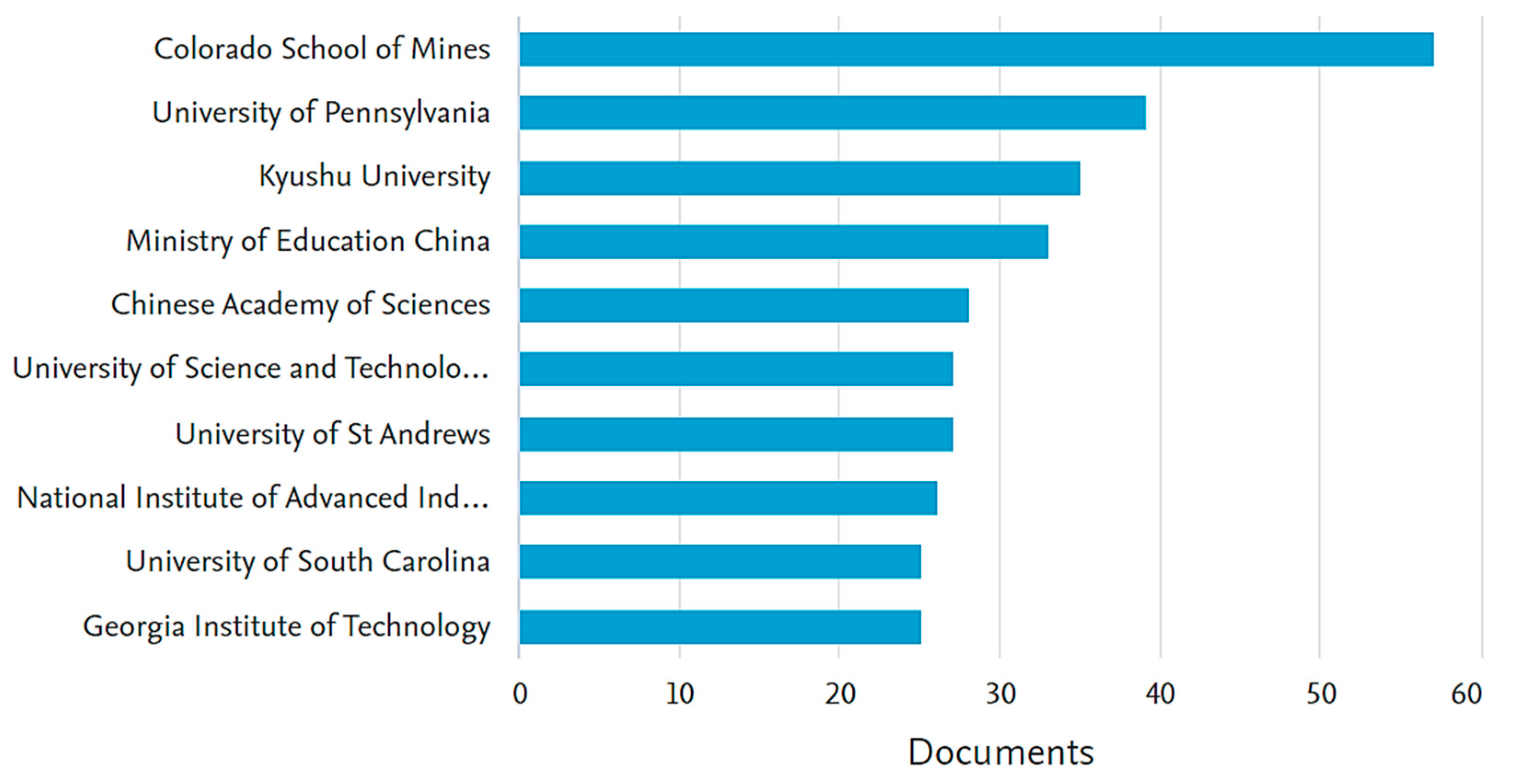
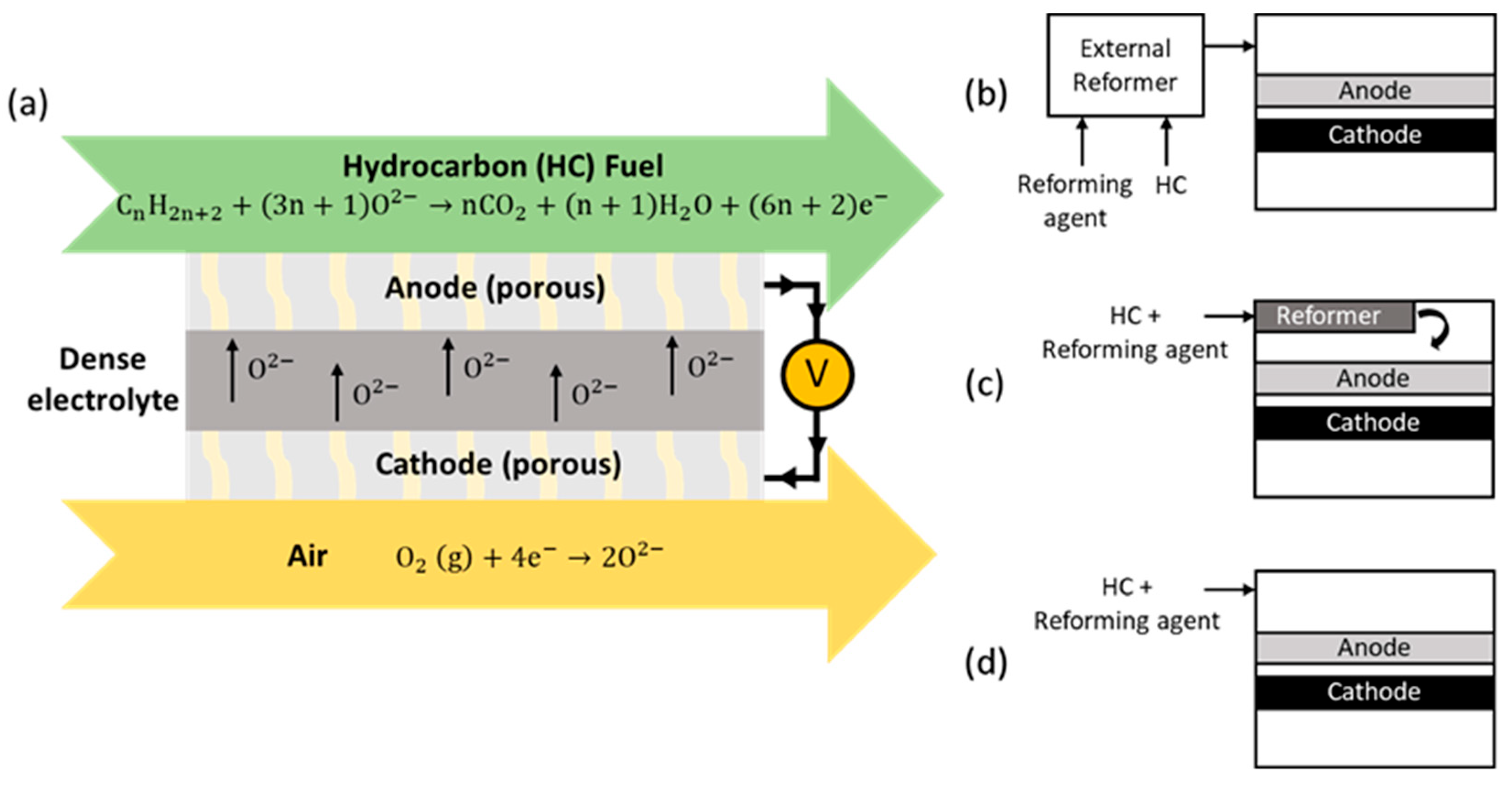
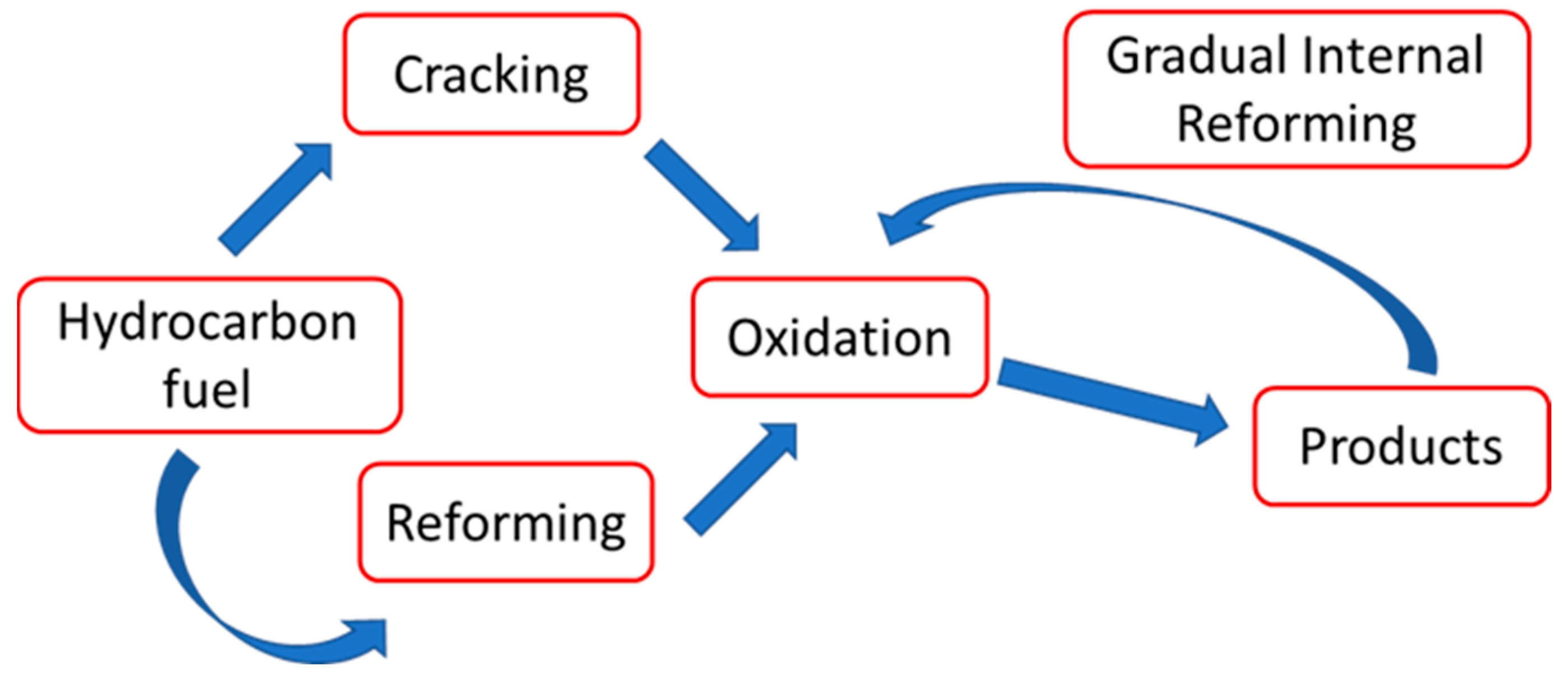
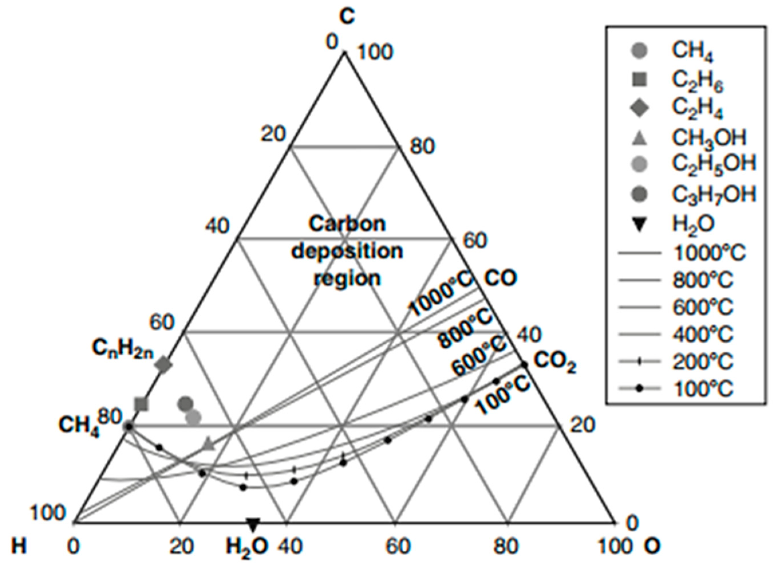
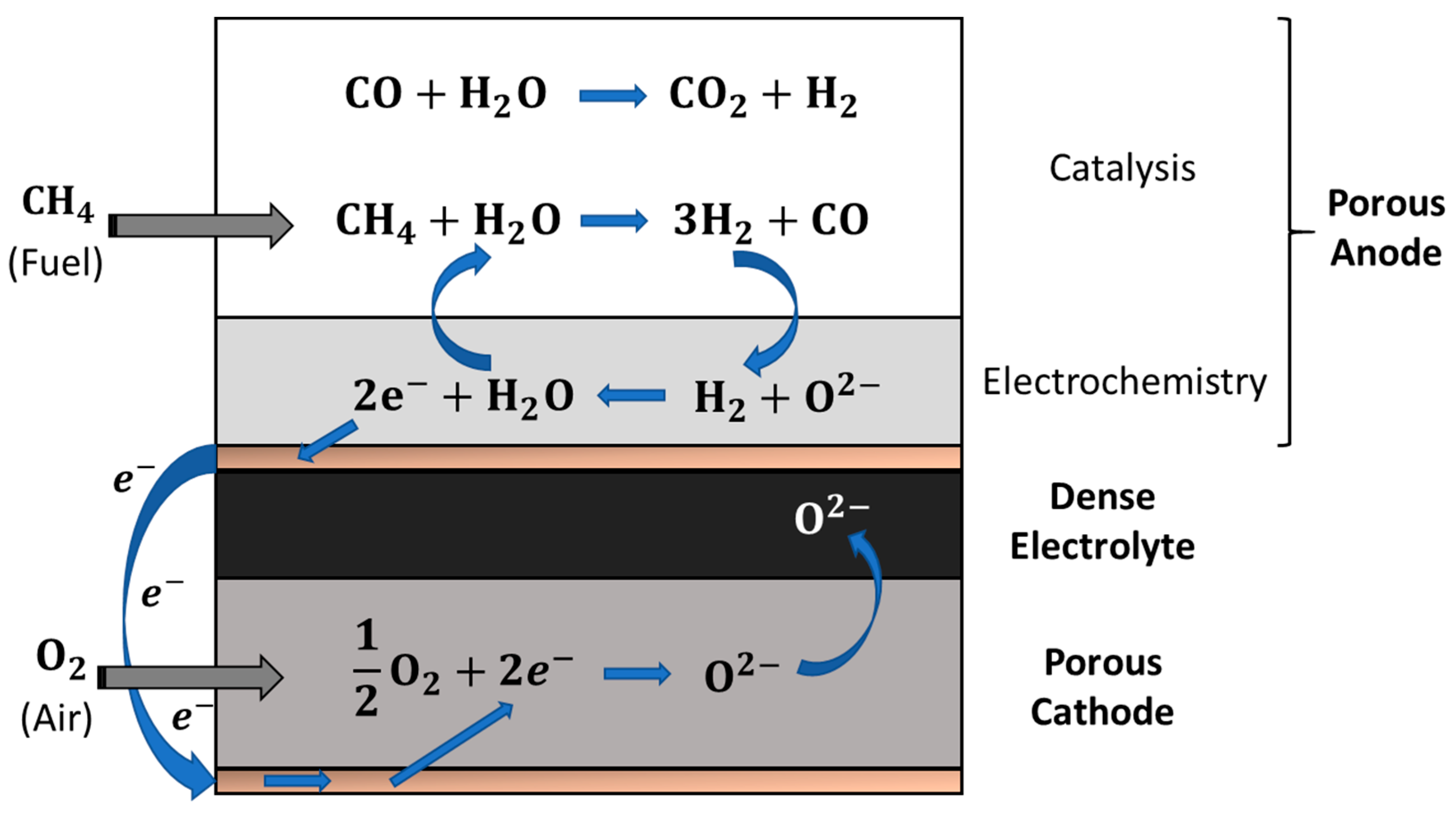
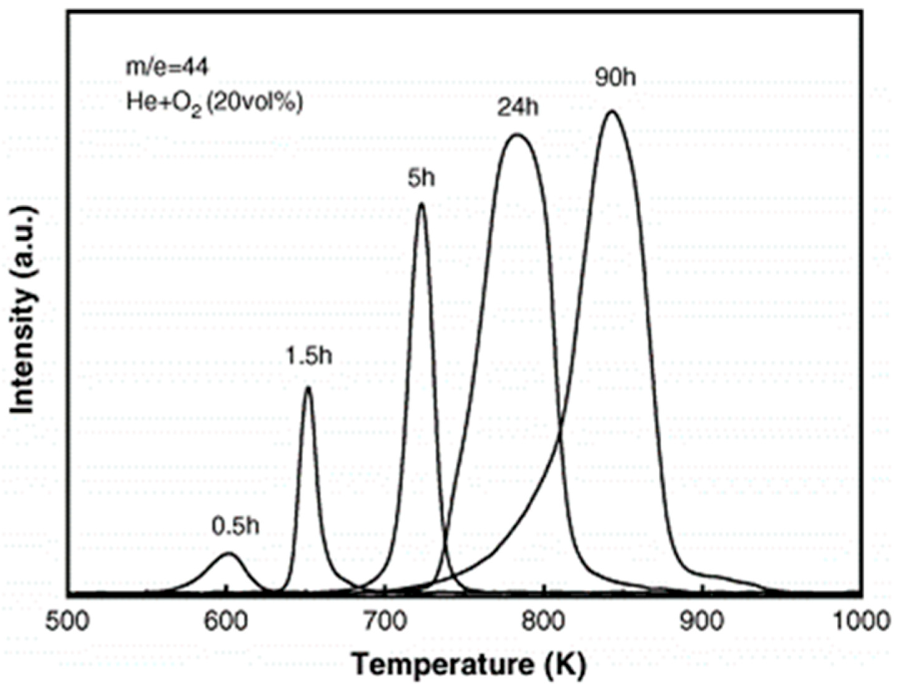
Table 1.
Research progress in methane-fuelled SOFCs topic.
| Anode | Electrolyte | Cathode | Fuel Stream | Temp. (°C) | OCV (V) | Pmax (W·cm−2) | Ref. |
|---|---|---|---|---|---|---|---|
| Ni-YSZ/YDC | YSZ | LSM | Wet CH4 (3% H2O) | 650 600 550 | 0.37 0.25 0.125 | [36] | |
| Ru-Ni-GDC | GDC | SDC | Dry CH4 | 600 | ~0.9 | 0.75 | [37] |
| NiO-YSZ | YSZ | LSM | H2/CH4 | 850 | 1.0 | / | [38] |
| Cu-Ni-CeO2-YSZ | YSZ | LSM | Dry CH4 | 800 | 1.0 | 0.33 | [39] |
| Ni-Cu-CeO2-YSZ | YSZ | LSM | H2/CH4/C4H10 | 700 | 1.0 | 0.14 | [40] |
| Ni-GDC-Ru | GDC | SSC | Dry CH4 | 600 | 0.9 | 0.75 | [41] |
| Ni-YSZ | YSZ | LSM-YSZ | Wet CH4 (3% H2O) | 800 | ~1.17 | 0.96 | [42] |
| Ni–YSZ | YSZ | LSCF-GDC | Wet CH4 (3% H2O) | 700 800 | ~1.2 | 0.52 1.27 | [43] |
| Ni-YSZ | YSZ | LSCF-SDC | Dry CH4 | 800 | ~1.1 | 0.35 | [44] |
| NiO-SDC | SDC | SSC | CH4 | 600 | 0.857 | 0.353 | [45] |
| Ni-SDC | SDC (~20 µm) | SDC-BSCF | 18.8% CH4 + 16.2% O2 + 65% He (by vol.) | 787 | 0.76 | [46] | |
| Ni-YSZ | YSZ (~1 mm) | LSM | Dry CH4 | 900 | 0.55 | ~0.055 | [47] |
| Ni-YSZ | YSZ | LSM | CH4 | 750 | 1.05 | 0.122 | [48] |
| Ni-YSZ | YSZ | LSM | CH4 | 750 | 0.92 | 0.036 | [49] |
| Ni-GDC Ni0.9Fe0.1-GDC | GDC | LSCF-GDC | Dry CH4 | 650 | ~0.8–0.82 | 0.30 0.34 | [50] |
| Ni-YSZ | YSZ | LSCF–GDC LSCF–GDC–Ag (10 wt%) | CH4/air mixture of 25/60 mL min−1 | 700 | ~0.9 ~1.0 | 0.06 0.12 | [51] |
| Ni-GDC | GDC | LSCF-GDC | CH4:H2O:N2 15:60:25 (i.e., S/C = 4) | 550 | 0.85 | 0.45 | [52] |
| Ni-GDC | GDC | LSCF-GDC | CH4/H2/H2O with a S/C = 2–3 | 550 | 0.72–0.78 | ~0.62 | [53] |
| Ni-YSZ | YSZ-SDC (5 µm–5 µm) | BSCF-SDC | CH4-O2 (2:1) | 700 | 1.07 | 1.5 | [54] |
| Ni-GDC | YSZ/GDC | LSCF | CH4/H2O S/C ratio = 0.079 | 610 | 1.08 | 0.26 | [55] |
| NiO-YSZ | YSZ | / | Dry CH4 | 850 | 1.2 | 0.566 | [56] |
| Ni-GDC Sn/Ni–GDC | GDC | LSCF | CH4 | 650 | 0.74–0.76 | ~0.37 ~0.47 | [57] |
| Ni-YSZ- BCZYYb | YSZ (3 µm) | LSCF-GDC with a GDC buffer layer | 36% CH4 + 36% CO2 + 20% H2O + 4% H2 + 4% CO | 750 | ~1.05 | 1.43 | [58] |
| Li-Ni-SDC Na-Ni-SDC | LSGM (300 µm) | SCCO-SDC | Wet CH4 (3% H2O) | 800 | 1.13 1.02 | 0.212 0.231 | [59] |
| NiO-YSZ | YSZ | LSCF | CH4:O2:N2 (1:0.21:0.79) at 19% fuel utilisation rate at 38% fuel utilisation rate | 650 | at 0.7 at 0.7 | ~0.17 ~0.22 | [60] |
| LaNi0.6Co0.4O3-Ni- BZCYYb | BZCYYb (3 µm) | BZCY-LSCF | Wet CH4 | 650 | ~1.1 | 0.98 | [61] |
| Ni-BZCYYb-PBM-Ni-Co | BZCYYb (~20 µm) | NBCaC-BZCYYb | CH4-CO2 (50:50%) | 700 | ~1.0 | 1.25 | [62] |
| Ni-LDC-Ni-SDC | SDC | SDC-BSCF | Wet CH4 | 650 | ~0.83 | 0.699 | [63] |
| Ni-BZY | BZY | BCFZY0.1 | CH4/C2H6/C3H8/N2 95/3/1/1% CH4 (O:C = 2) CH4 (O:C = 2.5) | 600 600 600 | ~0.98 ~0.98 ~0.98 | ~0.37 ~0.36 ~0.27 | [15] |
| NiO-YSZ | YSZ | GDC-LSCF | 20% CH4–80% CO2 | 750 | ~0.96 | 2.2 | [64] |
| Ni-BaO-CeO2@SiO2-NiO-YSZ | YSZ-SDC interlayer | BSCF-SDC | 30% CH4–70% Air | 800 | ~1.05 | 0.938 | [65] |
Ba0.5Sr0.5Co0.8Fe0.2O3−δ (BSCF); BaCo0.4Fe0.4Zr0.1Y0.1O3−δ (BCFZY0.1); BaZr0.1Ce0.7Y0.1Yb0.1O3−δ (BZCYYb); La2Ce2O7 (LDC); La0.8Sr0.2MnO3 (LSM); La0.9Sr0.1Ga0.8Mg0.2O3−δ (LSGM); La0.6Sr0.4Co0.2Fe0.8O3–Gd0.1Ce0.9O2 (LSCF-GDC); Sr2MgMoO6−δ (SMMO); Sm0.5Sr0.5CoO3 (SSC); Sr0.95Ce0.05CoO3−δ (SCCO); Ce0.8Sm0.2O2−x (SDC); NdBa0.75Ca0.25Co2O5+δ (NBCaC); (Y2O3)0.15(CeO2)0.85 (YDC).
Table 2.
Description of different types of reforming process.
| Reforming Process | Description |
|---|---|
| Steam reforming (SR) | A process in which high-temperature steam is added to hydrocarbons (fuel) that transform into simpler fuels: H2 and CO. |
| Dry reforming (DR) | A process in which CO2 acts as an oxidant in the presence of a suitable catalyst. |
| Partial oxidation (POx) | A chemical reaction between the hydrocarbons and oxygen (O2) typically from the air in a substoichiometric ratio. |
Table 3.
Heavier hydrocarbons-fuelled SOFCs.
| Anode | Electrolyte | Cathode | Fuel Stream | Temp. (°C) | OCV (V) | Max. Power Density (W·cm−2) | Ref. |
|---|---|---|---|---|---|---|---|
| Cu-CeO2-YSZ | YSZ (~20 µm) | LSM | C4H10 | 700 | 1.0 | 0.14 | [40] [166] |
| Cu-CeO2-YSZ | YSZ (60 µm) | LSM-YSZ | Dry n-C4H10 | 800 700 | ~0.9 | 0.18 0.12 | [26] |
| Ru-Ni-GDC | GDC (~40 µm) | SSC | Dry C2H6 Dry C3H8 | 600 | 0.85–0.9 | 0.716 0.648 | [37] |
| Ni-GDC-Ru | GDC | SSC | Dry C2H6 Dry C3H8 | 600 | 0.9 | 0.716 0.648 | [41] |
| Cu-CeO2-SDC | SDC (380 µm) | SDC-LSCF | Dry C4H10 | 700 | 0.794 | 0.170 | [167] |
| Ni-SDC (700 µm) | SDC (20µm) | BSCF-SDC | C3H8:O2:He 4:9:36 vol. ratio (ml min−1) | 500 | ~0.68 | ~0.44 | [168] |
| Cu-CeO2-SDC Cu-CeO2-LSGM Cu-CeO2-ScSZ | SDC LSGM ScSZ | SDC-LCSF LSGM-LSCF LSM–ScSZ | Dry n-C4H10 | 700 | −1.0 | 0.18 ~0.09 0.15 | [169] |
| Cu0.5Co0.5-CeO2-YSZ | YSZ (60 µm) | YSZ-LSM | Dry C4H10 | 700 800 | 1.1 | ~0.14 0.36 | [119] |
| Cu–CeO2–LSGM | LSGM (440 µm) | LSCF–LSGM (50:50 wt%) | Dry C4H10 | 700 | 1.06 | 0.115 | [170] |
| NiO-YSZ NiO-SDC | YSZ SDC | LSCF-GDC/LCSF | iso-C8H18:air: CO2 (5:9:86) | 570 670 770 570 | 0.97 to 1.02 ~0.82 | 0.1 0.3 0.6 ~0.35 | [134] |
| NiO-YSZ- PSZ | YSZ | LSCF-GDC | C3H8: O2: Ar (10.7:18.7:70.6) | 750 | ~0.92 | ~0.48 | [160] |
| NiO-SDC | SDC | LSCF-SDC | iso-C8H18: air (6:94) | 590 640 | ~0.8 | 0.6 0.68 | [158] |
| Cu-CeO2-YSZ | YSZ (60 µm) | LSM-YSZ | n-C10H22 | 700 750 800 | 1.0 | 0.1 0.17 0.24 | [148] |
| BaO/Ni-YSZ | YSZ (~15 µm) | SDC-LSCF | Dry C3H8 | 750 | ~1.0 | 0.88 | [163] |
| Ni-GDC | YSZ/GDC interlayer | LSCF | C4H10/H2O (S/C = 0.044) | 610 | 1.05 | 0.26 | [55] |
| Ni-YSZ-BZY-Ni-YSZ | YSZ-SDC | LSCF | Wet iso-C8H18 (6.5%inAr) (S/C ratio of 1/17) | 750 | ~1.05 | 0.6 | [156] |
| Cu–Fe/ceria–YSZ | YSZ | YSZ-LSM | n-C4H10 | 800 | ~1.18 | 0.240 | [171] |
| CMF-LSFM CMF-LSFM + 10 wt% RuO2 | LSGMC (~0.3 mm) | SSC | C3H8 | 800 | 1.09 1.122 | 1.08 1.583 | [164] |
| Ni-GDC Rh-Ni-GDC | GDC (1.3 ± 0.1 mm) | PSCF3737 | n-C4H10:steam:N2 (10:120:70) | 600 | 0.9–0.95 | ~0.011 ~0.024 | [152] |
| Ni-SDC | ScCeSZ (12 µm) | Pr6O11-P434L alloy | 45%C2H5OH–55%H2O | 700 | ~1.01 | 0.87 | [172] |
Ba0.5Sr0.5-Co0.8Fe0.2O3−δ (BSCF); BaZr1−xYxO3−δ (BZY); Ce0.6Mn0.3Fe0.1O2-La0.6Sr0.4Fe0.9Mn0.1O3 (CMF-LSFM); La0.8Sr0.2Ga0.8Mg0.15Co0.05O3 (LSGMC); Pr0.3Sr0.7Co0.3Fe0.7O3 (PSCF3737); Sm0.5Sr0.5CoO3 (SSC); scandia-ceria-stabilized zirconia (ScCeSZ).
Disclaimer/Publisher’s Note: The statements, opinions and data contained in all publications are solely those of the individual author(s) and contributor(s) and not of MDPI and/or the editor(s). MDPI and/or the editor(s) disclaim responsibility for any injury to people or property resulting from any ideas, methods, instructions or products referred to in the content. |
© 2023 by the authors. Licensee MDPI, Basel, Switzerland. This article is an open access article distributed under the terms and conditions of the Creative Commons Attribution (CC BY) license (https://creativecommons.org/licenses/by/4.0/).
Share and Cite
MDPI and ACS Style
Rabuni, M.F.; Li, T.; Othman, M.H.D.; Adnan, F.H.; Li, K. Progress in Solid Oxide Fuel Cells with Hydrocarbon Fuels. Energies 2023, 16, 6404. https://0-doi-org.brum.beds.ac.uk/10.3390/en16176404
AMA Style
Rabuni MF, Li T, Othman MHD, Adnan FH, Li K. Progress in Solid Oxide Fuel Cells with Hydrocarbon Fuels. Energies. 2023; 16(17):6404. https://0-doi-org.brum.beds.ac.uk/10.3390/en16176404
Chicago/Turabian StyleRabuni, Mohamad Fairus, Tao Li, Mohd Hafiz Dzarfan Othman, Faidzul Hakim Adnan, and Kang Li. 2023. "Progress in Solid Oxide Fuel Cells with Hydrocarbon Fuels" Energies 16, no. 17: 6404. https://0-doi-org.brum.beds.ac.uk/10.3390/en16176404
Note that from the first issue of 2016, this journal uses article numbers instead of page numbers. See further details here.