
Analysis of Direct Torque Control Response to Stator and Rotor Faults in Permanent Magnet Synchronous Machines


Department of Electrical and Computer Engineering, Michigan State University, East Lansing, MI 48824, USA
*
Author to whom correspondence should be addressed.
Energies 2023, 16(19), 6940; https://0-doi-org.brum.beds.ac.uk/10.3390/en16196940
Submission received: 30 June 2023
/
Revised: 27 September 2023
/
Accepted: 2 October 2023
/
Published: 3 October 2023
(This article belongs to the Special Issue Condition Monitoring and Failure Prevention of Electric Machines)
Abstract
:Direct-torque-control-driven permanent magnet synchronous machines eliminate the need for a position sensor while providing improved torque dynamics. However, the structure, regulation principle and nature of compensation of hysteresis-based controllers used in direct torque control impacts performance under faulty operating conditions. This paper analyzes the reaction of direct torque control to the presence of various faults that occur in permanent magnet synchronous machines. The analysis presented reveals that the direct torque control injects a negative sequence voltage and manipulates the torque angle to meet the control objectives when a fault occurs. The co-simulation of finite element analysis and a multi-physic circuit simulator is used to validate the response of the hysteresis-based controller to the machine health. The results indicate that the hysteresis comparators have the ability to mask the impact of the faults in the direct-torque-control-driven permanent magnet synchronous machines.
1. Introduction
Permanent magnet synchronous machines (PMSMs) are widely used in various industries such as transportation, manufacturing and renewable energy [1,2]. The simple structure of direct torque control (DTC), coupled with its encoderless operation and fast dynamics, are of great interest for PMSM [3]. Nevertheless, the occurrence of faults, such as turn-to-turn short circuit (TTSC), high resistance contact (HRC), static eccentricity and partial demagnetization, remains a concern [4]. As PMSMs are increasingly utilized in safety critical applications, it is important that the controller can maintain a safe, stable operation independent of the machine health state [5]. As discussed in reference [6], variations in stator resistance and measurement errors can degrade performance and result in torque oscillations at the electrical frequency. Under heavy load or high speed, it has been shown in reference [7] that DTC cannot satisfy both the flux and torque control requirements simultaneously, resulting in the torque losing control. Considering that the presence of faults impacts the characteristic parameters of the PMSM, faults can prevent the smooth drive operation of DTC and potentially lead to catastrophic losses if not detected and mitigated in their early phases. Hence, fault diagnosis in DTC-driven PMSM is paramount to ensuring reliable drive operation.
Most of the fault diagnosis algorithms for inverter-driven PMSMs were developed for field-oriented control (FOC) drives [8,9,10,11,12,13]. However, it is important to consider that the different structure, regulation principle and nature of compensation for controllers can affect the fault diagnosis. As shown in reference [4], the controller type impacts the use of motor voltage signature analysis (MVSA) for fault diagnosis. The MVSA diagnostic strategy has lower accuracy for the DTC-driven PMSM than the FOC-driven PMSM. The lack of a consistent trend in the frequency spectrum of the voltage command for the DTC-driven PMSM under faulty operating conditions leads to higher incidence of incorrect fault classification.
Understanding the impact of faults on drive operation and its corresponding reaction is a fundamental aspect of developing effective fault detection and separation methods. This becomes especially critical in the context of inverter-driven PMSM, where the compensatory capability of the drive system impacts the fault detectability [14]. In the case of DTC-driven PMSM, the electromagnetic torque error and stator flux linkage error are compensated directly through hysteresis comparators. Therefore, it is essential to comprehensively examine the nonlinear behavior that arises from the utilization of flux and torque hysteresis comparators, both in healthy and faulty conditions. Some efforts have been made to develop fault diagnosis techniques suitable for DTC-driven PMSMs [15,16,17,18,19,20,21,22]; however, the existing literature still lacks a comprehensive understanding of the potential ramifications of these faults on the operation of DTC-driven PMSMs.
This work analyzes the operation of DTC-driven PMSMs under four common faults: TTSC, HRC, static eccentricity and partial demagnetization. The analysis provides insight into the response of DTC to faulty motor conditions and its effect on fault detection, fault separation and control stability. The major contributions of this work are as follows:
- (1)
- Its thorough analysis of the DTC reaction to the faulty operation of a PMSM; and
- (2)
- Its summary of the challenges in stability for DTC-driven PMSMs.
These contributions facilitate the further development of DTC schemes that are robust to the presence of faults in PMSMs.
2. Faulty Operation of DTC-Driven PMSM
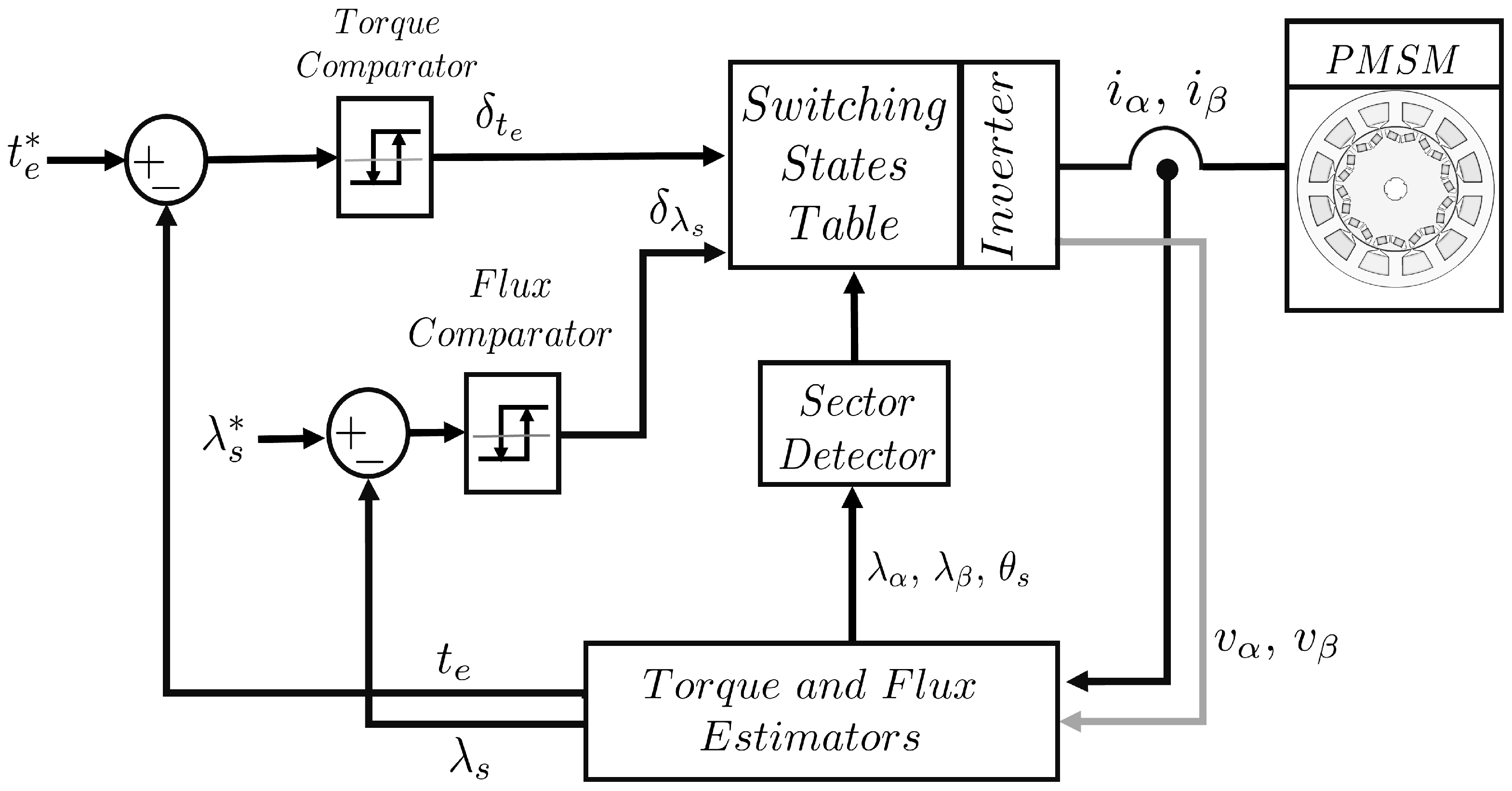
The schematic diagram of DTC drive, developed for PMSMs in reference [23], is shown in Figure 1. Measured currents () and estimated voltages () in the stationary frame are required to estimate the stator flux linkages (), as described in (1).
where, () is the phase resistance and () is the initial condition for flux linkage estimation. Consequently, the electromagnetic torque () is estimated using the cross product of the current and stator flux linkages, as described in (2), where () is the number of pole pairs.
Machine currents or voltages will include additional harmonics as a result of the comparator’s response to the fault occurrence. Therefore, a thorough analysis of the reaction of the flux and torque hysteresis comparators upon a fault occurrence is essential. However, it is known that the nonlinear nature of the hysteresis comparators in DTC poses challenges to addressing this problem analytically [24,25,26]. Here, the behavior of the current under faulty conditions is described analytically to investigate the DTC reaction.
The initial consequence of the fault occurrence is the generation of a negative sequence component in addition to the positive sequence of the machine stator currents. The resulting machine current space vector () is given in (3).
The variables and represent the magnitudes of the positive and negative sequence components of the machine currents, while and represent their phase angles, respectively. As the stator current is required for the flux linkage estimation in (1), the resulting stator flux linkage space vector is described in (4).
where, and are the positive and negative sequence component of the stator flux linkages while and are their phase angles, respectively. Since the electromagnetic torque is a function of the stator currents and flux linkages of the machine, as described in (2), the resulting electromagnetic torque would be the sum of three parts, given in (5).
The machine output torque, , is produced by the interaction of the positive sequence components of the machine current and flux linkage, described in (6).
The DC component of the torque , described in (7), is a function of the negative sequences introduced by the fault occurrence.
Finally, is a torque component oscillating at double fundamental frequency (), as shown in (8); it is introduced in the machine output torque by the fault.
3. Response of Flux and Torque Comparators
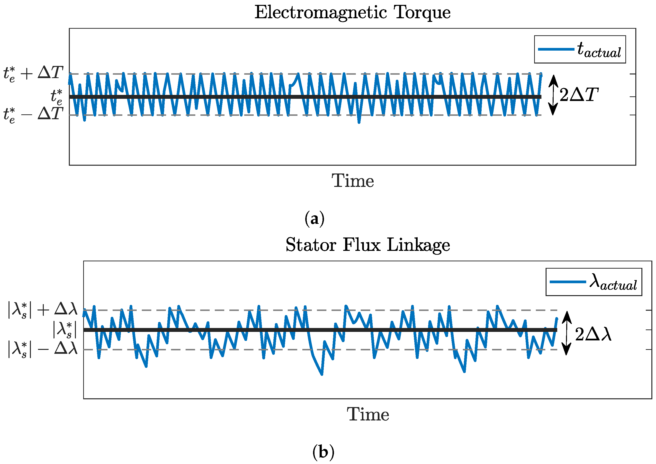
The DTC technique employs hysteresis comparators to regulate the magnitude of stator flux linkage and electromagnetic torque. The bandwidth in the DTC scenario is determined by the torque and flux hysteresis bands ( and ), respectively. Figure 2 presents the torque and flux variation within the hysteresis bands.
The bands can either have fixed values, that remain constant regardless of operating conditions [27], or they can be percentages of a preset value based on operating conditions [28]. Alternatively, they can be variables that enable nearly constant switching frequency [29]. The utilization of wider hysteresis bands leads to a reduction in bandwidth and switching frequency due to the infrequent violation of the hysteresis bands during the control cycle. Conversely, a high controller bandwidth necessitates narrow bands, leading to increased switching frequency due to the likelihood of torque and flux errors exceeding the hysteresis bands during a significant portion of the control cycle. In general, DTC permits deviations in the estimation of flux and torque, provided that they fall within the predetermined tolerance margin established by the hysteresis band. Nonetheless, the estimated torque and flux linkage should follow the reference ones regardless of the machine condition, whether it is healthy or faulty.
3.1. Flux Comparator Response
Since a negative sequence component appears in the flux linkages due to its presence on the current, the flux comparator should cancel it by imposing another negative sequence component () in the flux linkage, as described in (9).
As a result, even in the presence of the fault, the actual flux linkage of the machine would follow the reference flux linkage:
Considering (1), the DTC drive injects a negative sequence component on the reference voltages to inject the cancellation term (). As a result of (9), the static torque error in (7) and the first term of (8) are cancelled. However, the second term of the torque dynamic error in (8) remains.
The flux hysteresis band limits the maximum acceptable change in the stator flux linkage, which, in turn, limits the negative flux linkage sequence component that can be generated by applying a negative voltage sequence, as expressed in (11).
The upper limit of the negative voltage sequence that the DTC flux comparator can apply in response to the flux linkage error is directly related to the flux hysteresis band, as described by (12).
3.2. Torque Comparator Response
The regulation of output torque in DTC drive is achieved through the use of a torque hysteresis comparator. As a result, it is expected that the output torque will conform to the torque reference regardless of the condition of the machine. However, the flux comparator response does not eliminate all the consequences of the fault, as the second term of the torque dynamic error in (8) remains. This error is tolerated by DTC as long as this error falls within the hysteresis band of the torque comparator. However, if the error exceeds the maximum allowable torque error, the torque comparator must find an alternative method to compensate for it.
The variables that DTC can adjust to maintain the desired torque can be known by considering the torque equation given in (13).
where, () are the inductances in the synchronous rotating frame; () is the magnet flux linkage; and () is the torque angle, which represents the difference between the stator flux linkage angle () and the rotor flux linkage angle (). It is clear that the two variables that DTC can adjust are and . DTC has the capability to adjust the stator flux linkage vector during the transient conditions to either accelerate it to increase the torque angle and generate additional torque, or decelerate it to reduce the torque angle and produce less torque. Under steady-state conditions, the stator flux linkage vector rotates at the same speed as the rotor flux linkage vector, such that the torque is constant. However, is almost fixed as it is controlled by the flux comparator. Therefore, the only option for DTC to respond to the torque error is by manipulating the torque angle.
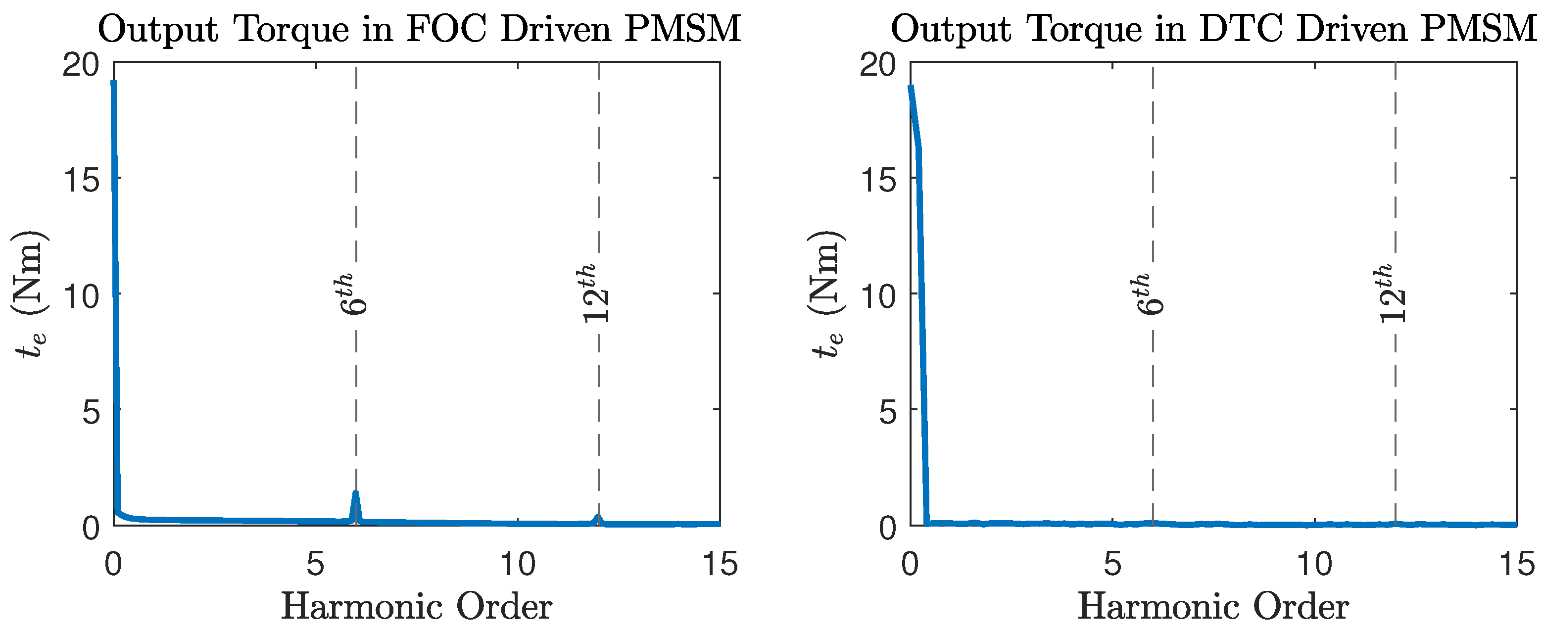
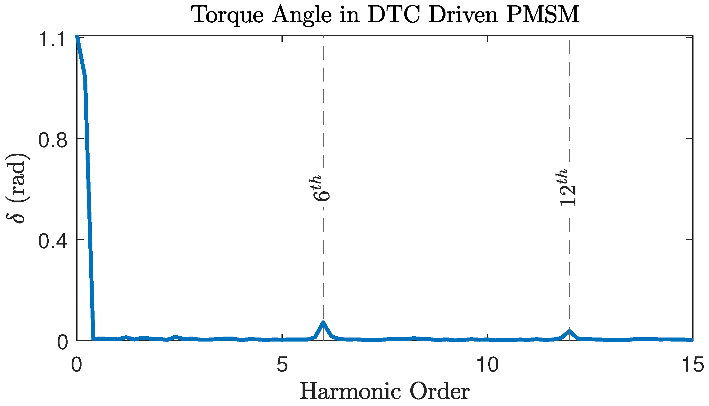
According to [30], the PMSM torque ripple exhibits harmonic orders that are multiples of the sixth harmonic, , where is the machine electric frequency and . The frequency spectrum, obtained through Fast Fourier Transform (FFT), of the torque produced by an IPMSM driven by Field-Oriented Control (FOC) and DTC are provided in Figure 3. It is evident that the FOC driven PMSM exhibits significant magnitudes of the 6th and 12th harmonics in its output torque, whereas such high magnitudes are not observable in the case of DTC. However, if the magnitude of the second term in (8) increases the torque beyond the hysteresis bands (), DTC will attempt to compensate for it in order to maintain the torque error within the band. Since the DTC drive provides the ability to adjust the torque angle (), any induced harmonics are expected to manifest in the torque angle instead of the torque. This can be observed in the frequency spectrum of the torque angle depicted in Figure 4.
The torque comprises two components: the magnetic torque () and the reluctance torque (), as shown in (14).
The 6th and 12th harmonics are introduced into the torque angle for both the magnetic and reluctance torque equations given in (14), as shown in (15) and (16).
The terms , , , and correspond to the amplitudes and phases of the 6th and 12th harmonics present in the frequency spectrum of the torque angle. The trigonometric identity described in (17) is used to expand the electromagnetic and reluctance torque equations as shown in (18) and (19).
By considering the presence of the 6th and 12th harmonics in the torque angle frequency spectrum, it can be observed that the magnitudes of and are subject to multiplication by and , respectively. Besides that, additional terms are present in and . These offset terms are and . In the presence of the fault, the torque of the machine would attempt to follow the reference torque through variations in the torque angle.
4. Impact of Variations in Stator Flux Linkage Angle
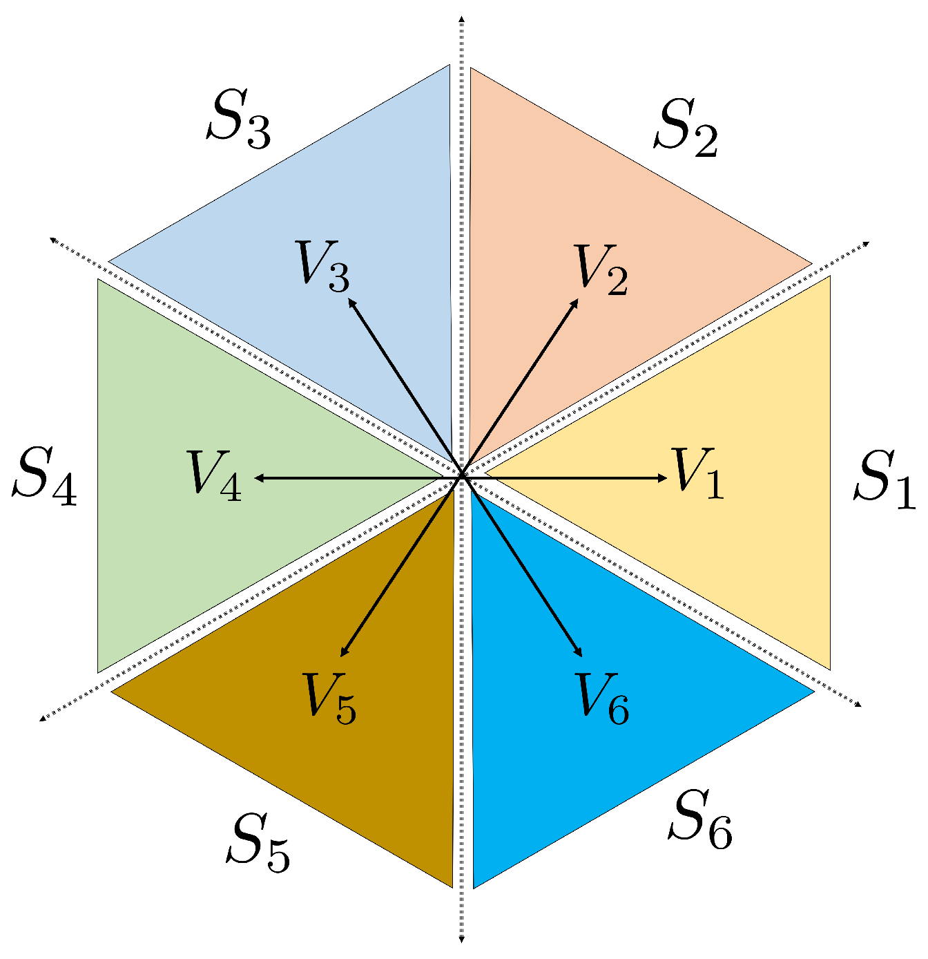
The robustness and tolerance of DTC can also be attributed to its discrete control action, which involves selecting a finite set of possible actions rather than continuous modulation. The finite set of actions, namely the voltage vectors, is chosen based on heuristics and system dynamics, whereby an exact position of the stator flux linkage vector is not necessary. Figure 5 presents the sector partitions and voltage vectors available for selection in DTC. It consists of six voltage vectors () within six sectors () that are displaced by . The appropriate voltage vector is chosen as shown in Table 1.
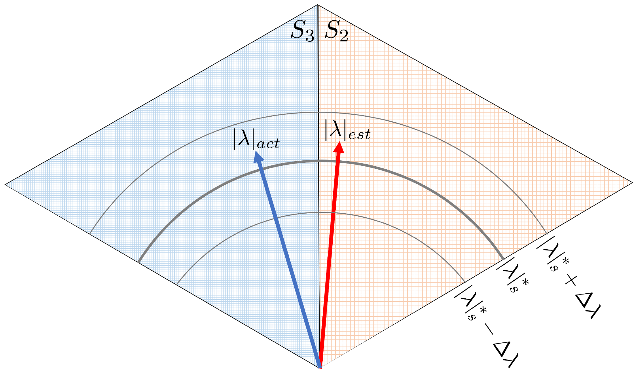
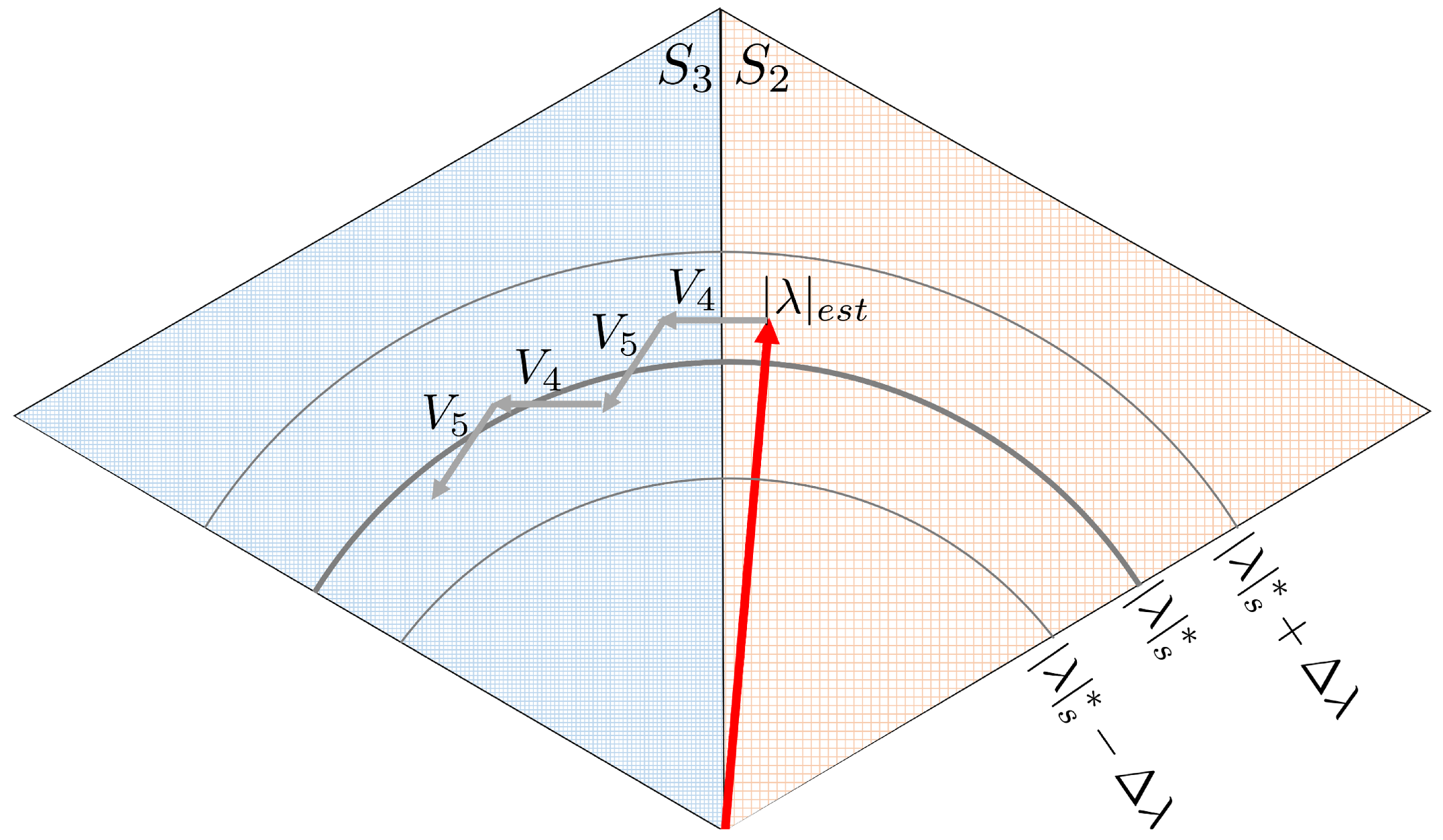
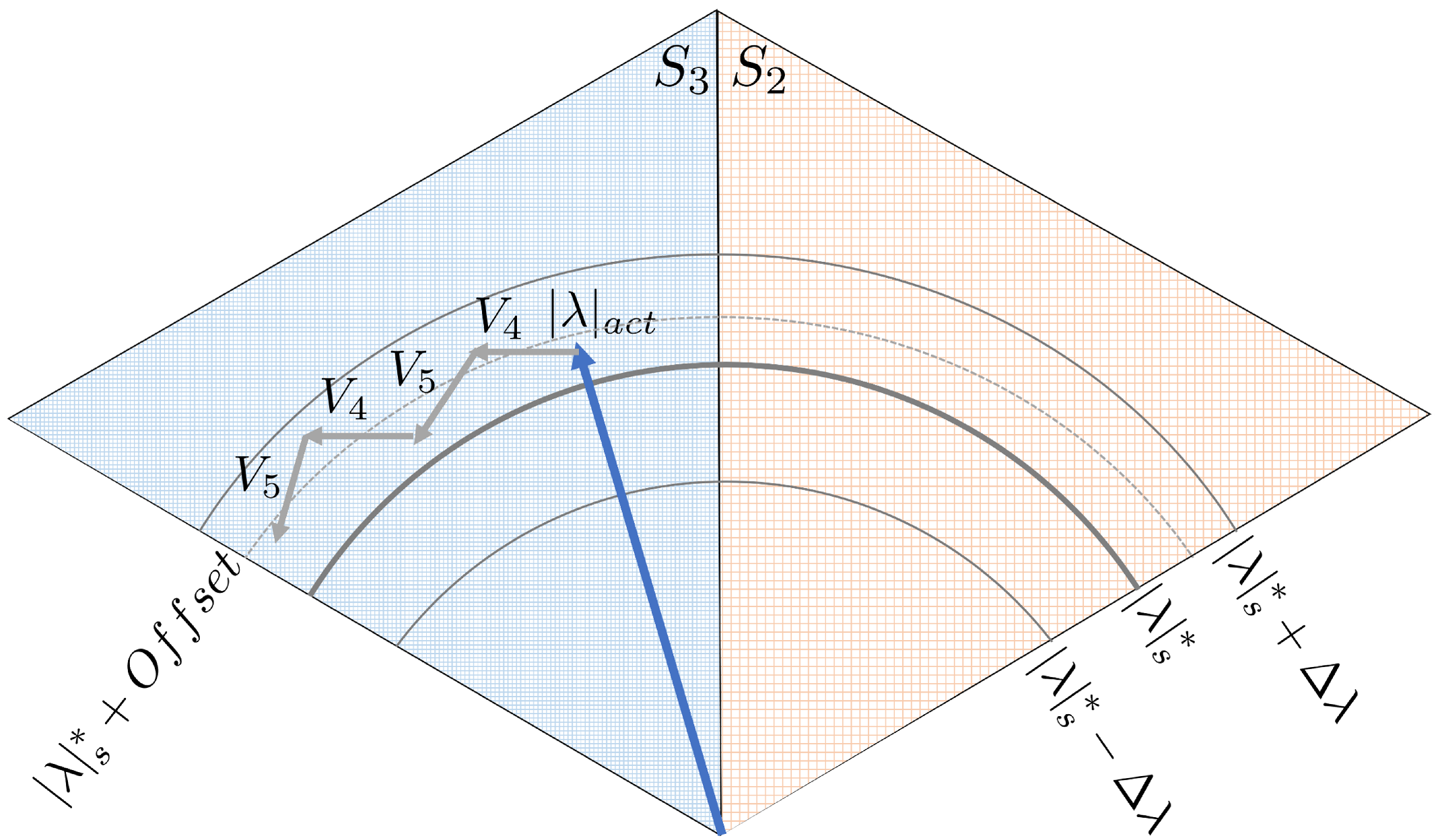
As described in reference [18], the accurate estimation of the flux of a faulty PMSM requires additional terms that are not included in (1). Provided that the actual and estimated stator flux linkage vectors are in the same sector, identical voltage vectors will be applied. However, if they are situated at the boundaries between sectors, different voltage vectors are applied, which will lead to a deviation in both desired torque and flux. For illustration purposes, the error in estimating the flux caused by the fault has been assumed to result in the estimated stator flux linkage vector () being in the second sector, while it is assumed that the actual vector () is in the third sector, as depicted in Figure 6. It is clear that the estimated value of is higher than the reference value, which requires the selection of a voltage vector that can reduce the estimated value of . By assuming that the electromagnetic torque should be increased at this instant, the voltage vector () should be applied to the estimated stator flux linkage based on Table 1 since it lies in the second sector. Figure 7 presents the trace of () where () results in moving the vector from the second sector to the third one. Subsequently, a varying pattern is introduced now between and to the estimated stator flux linkage vector, which is located in the third sector, in order to align it with the reference vector.
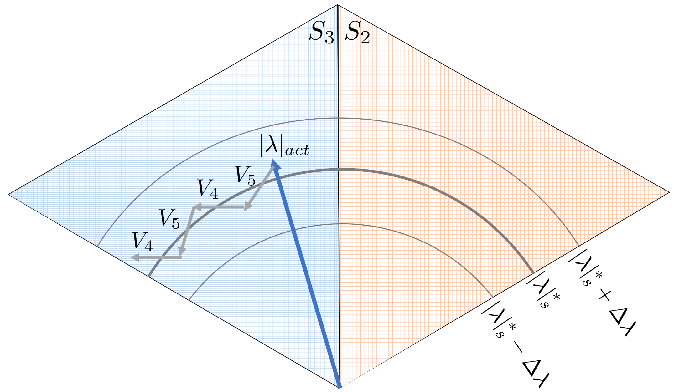
Nonetheless, when dealing with the actual stator flux linkage vector, the voltage vector () must be utilized because the flux vector is situated in the third sector. This decision is supported by the information provided in Table 1, where a decrease in flux linkage is required while simultaneously increasing torque. Figure 8 depicts the trace of the actual stator flux linkage vector in the case that the voltage vector () is applied first.
As the feedback loop of DTC relies on the estimated stator flux linkage signal instead of the actual one, the actual stator flux linkage vector will follow the same voltage vector pattern illustrated in Figure 7. However, this can cause inaccuracies in the control process, leading to differences between the actual stator flux linkage magnitude and the desired reference value, as shown in Figure 9, even if the estimated value is shown to be properly regulated. The actual stator flux linkage will be adjusted to a new reference position that takes into account the offset caused by the erroneous control action. Nonetheless, if the error is not substantial, it may be within the hysteresis bands. Hence, the unmodeled fault dynamics in the flux estimation lead to unobservable effects of the fault that may be tolerated by DTC. However, if the changes in the PMSM characteristic parameters due to the fault violate (20), the controller may become unstable, as discussed in reference [31].
5. Numerical Results
The validation of the DTC response to the presence of faults is conducted numerically. A co-simulation study of the DTC drive and finite element model of a PMSM within ANSYS software is conducted.
5.1. Numerical Setup
The DTC-driven PMSM is simulated for both healthy and faulty cases. The specification of the finite elements model (FEM) of the simulated PMSM in MAXWELL simulator are listed in Table 2 while the settings of the implemented DTC drive in SIMPLORER simulator are listed in Table 3.
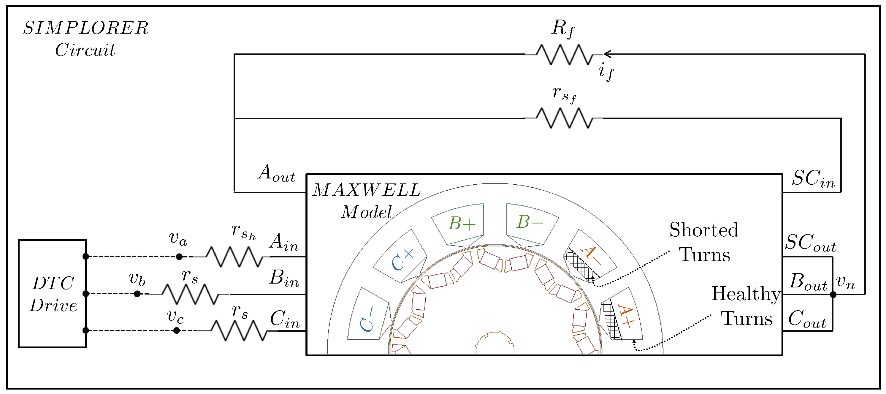
To simulate the faulty conditions of DTC-driven PMSM, modifications are made to both the geometry of the studied machine and its drive circuit. To model the TTSC fault occurring within the coils of the phase A winding, the coil area is divided into two separate parts: one comprising the healthy turns and the other consisting of the shorted turns, as described in Figure 10. The shaded section within the slot, allocated for phase A winding, represents the turns, located near the air gap, shorted through a fault resistance. The TTSC severity is indicated by the number of faulty turns () and the short circuit resistance (). The non-shaded section within the slot indicates the remaining healthy turns of the phase A winding. To mimic the HRC fault, a resistance () is connected in series with the phase resistance (). Here, the fault is implemented in phase B, and the severity of the fault is indicated by varying the magnitude of . To model the partial demagnetization fault in the PMSM, the remnant flux density of selected magnets is reduced. Each pole in the studied machine includes two magnets of V-shape. The material of the demagnetized magnets is replaced with a new material having zero flux density, while the other properties remain unchanged. To implement the static rotor eccentricity, the rotor and its rotation axis are moved in the direction of the fault while keeping the stator coordinates fixed. The fault severity is determined by shifting the components along the positive Y-axis, using different values () relative to the length of the air gap (). The severity levels of each fault are given in Table 4.
5.2. Flux Comparator
To evaluate the response of the flux comparator to fault presence in DTC-driven PMSM, the symmetrical components of the commanded voltages are studied. The positive, negative, and zero sequence components of the commanded voltages () are computed using (21).
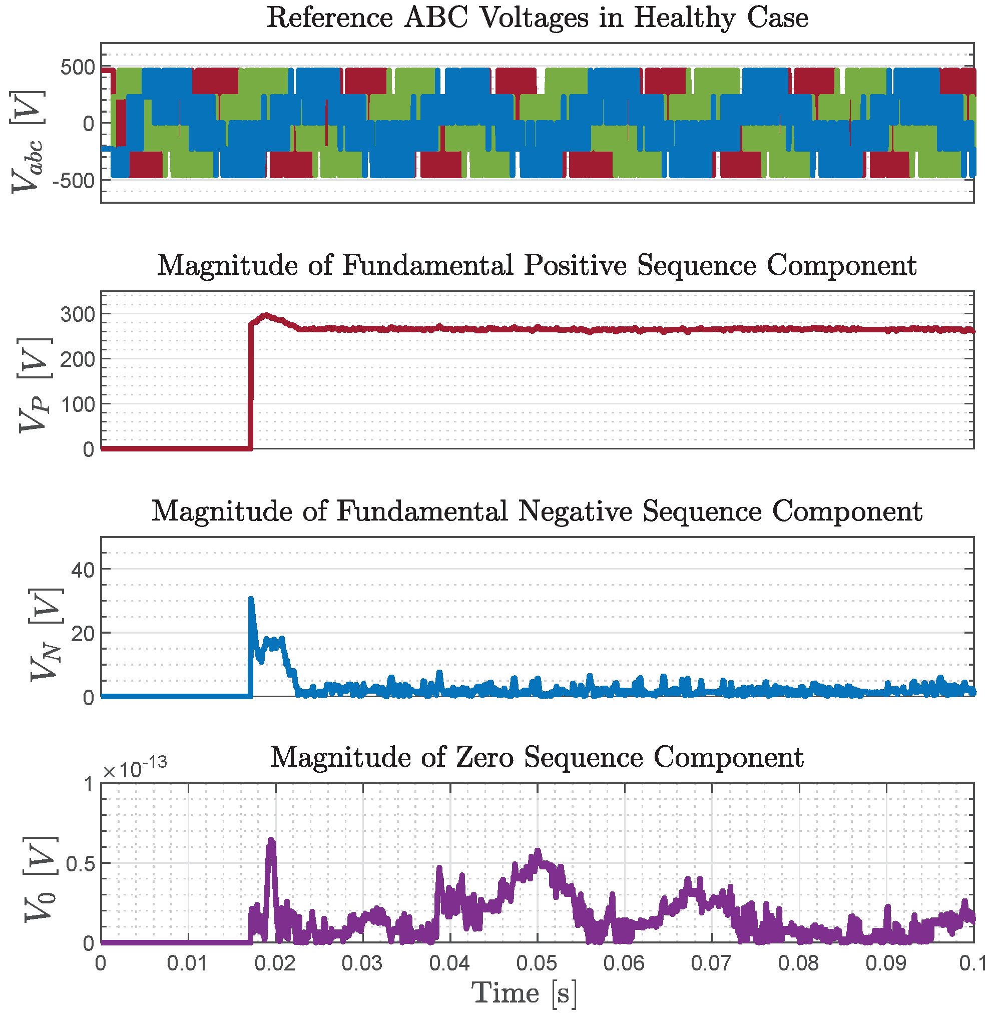
where . Under normal operating conditions, the negative sequence component is absent because the commanded voltages are balanced, as shown in Figure 11.
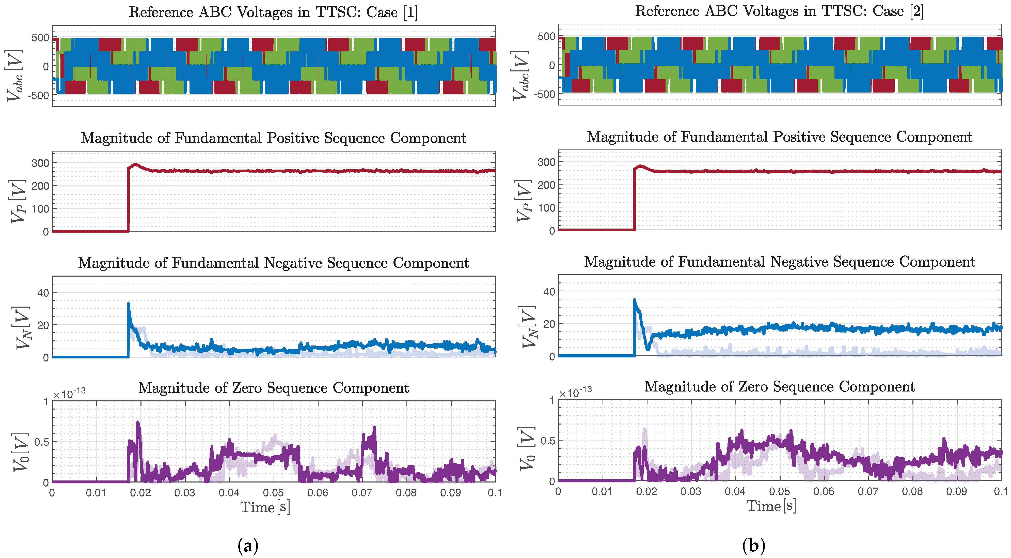
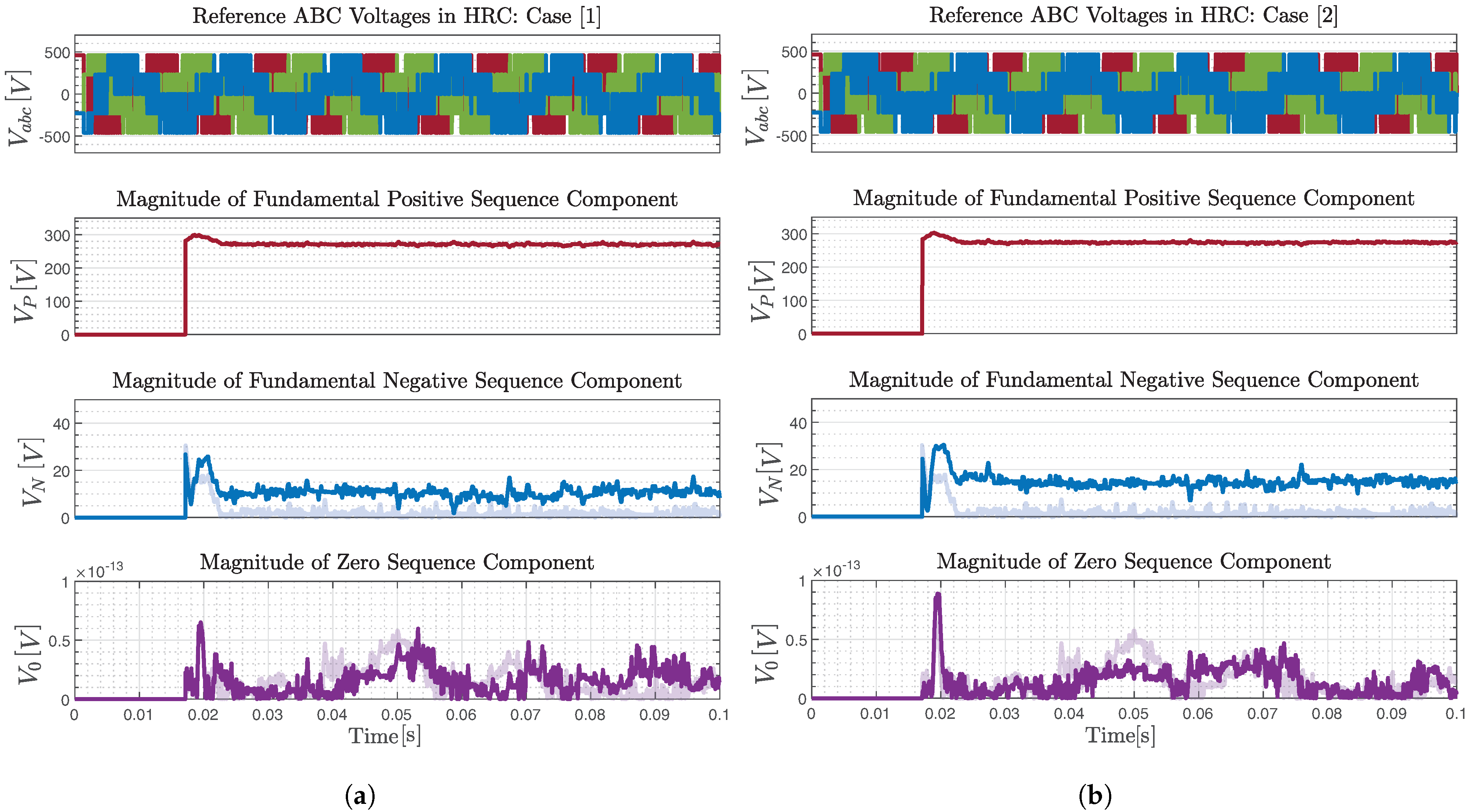
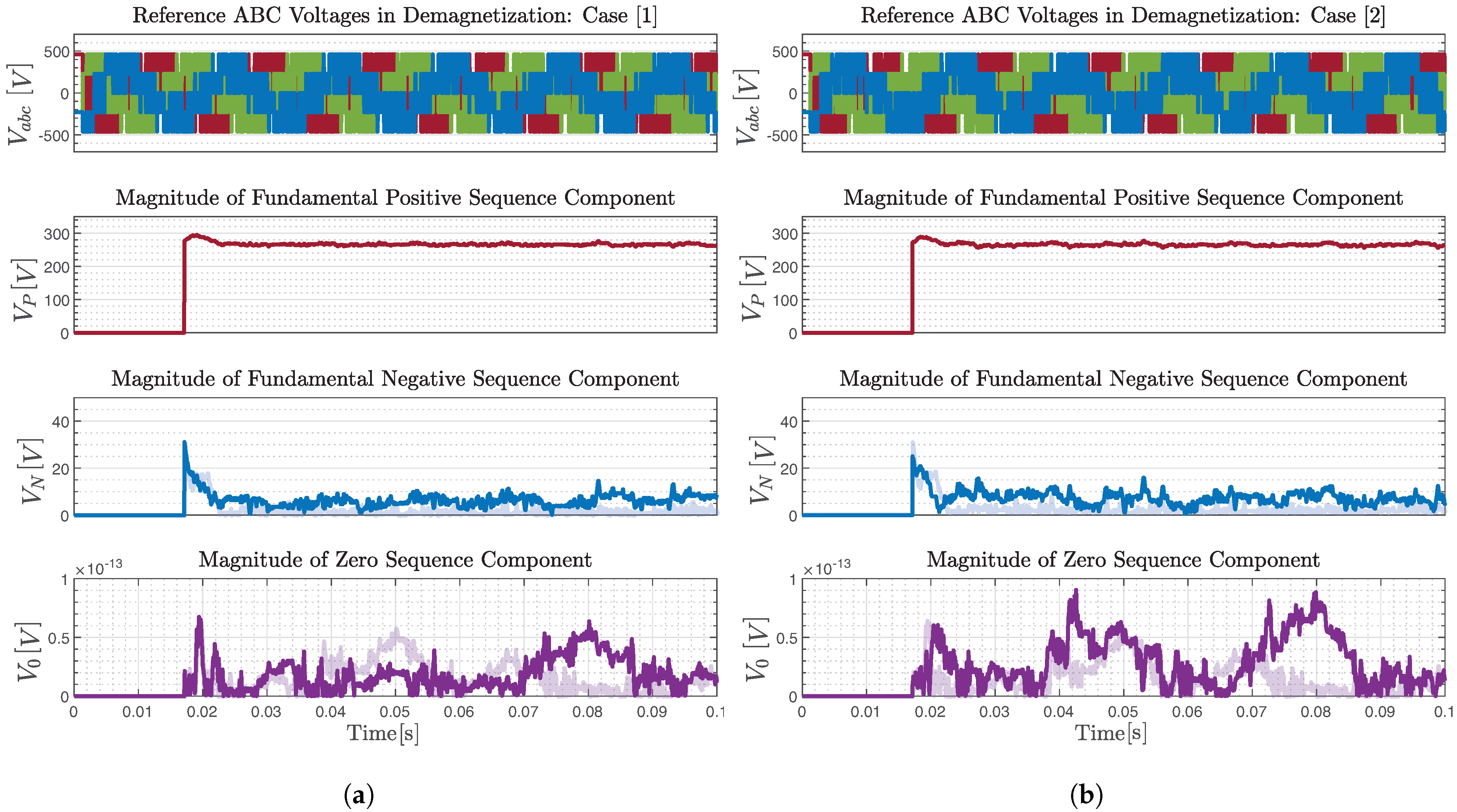
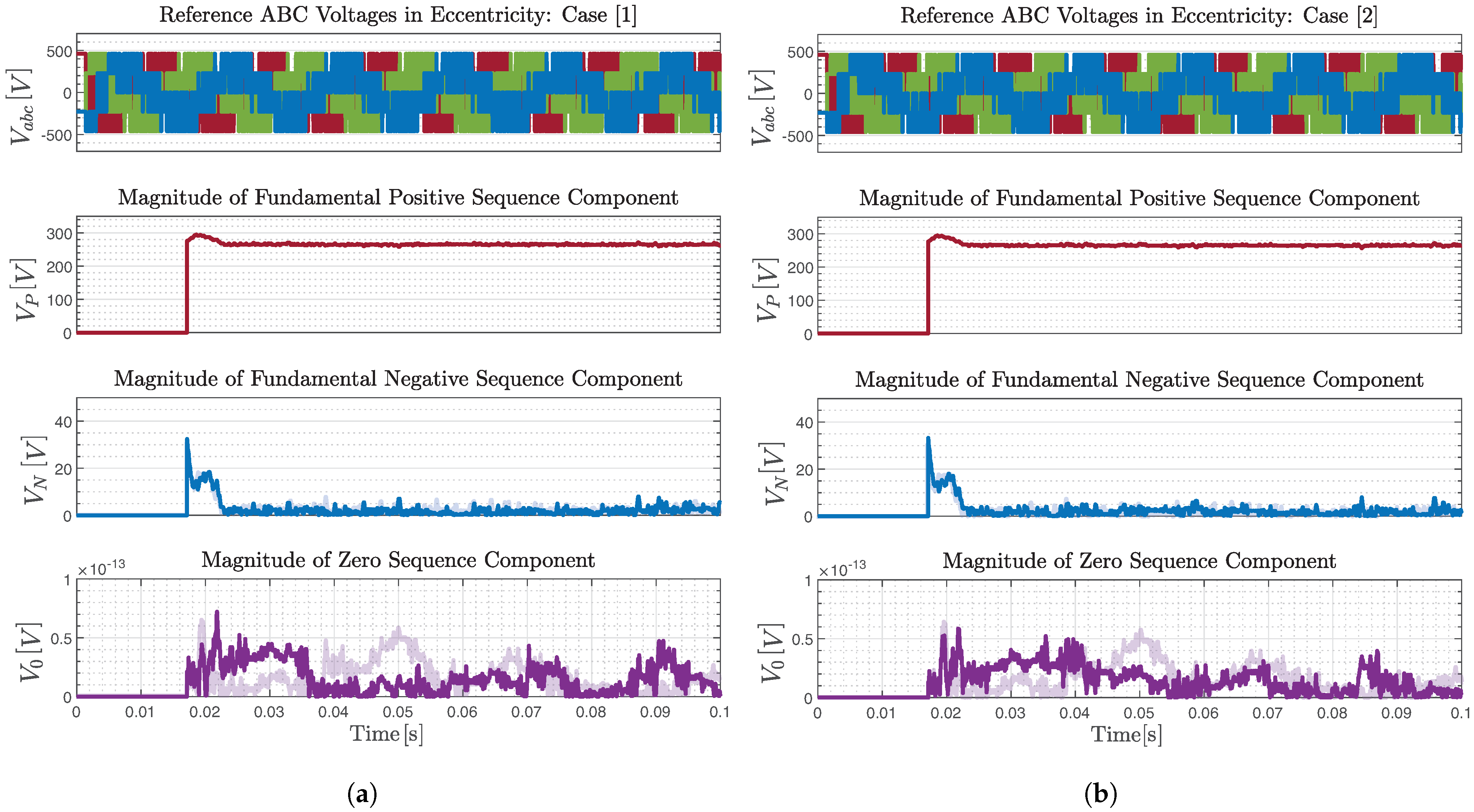
In the event of a fault, the commanded voltages become unbalanced, which causes the negative sequence voltage component to appear for TTSC, HRC and demagnetization faults, as shown in Figure 12, Figure 13 and Figure 14. This component helps to mitigate the effect of the fault on the stator flux linkage magnitude. However, the negative sequence voltage is nearly zero under eccentricity fault, as shown in Figure 15. The absence of the negative sequence voltage under eccentricity fault is similar to the healthy case, Figure 11. It is expected that the operation of the DTC-driven PMSM will remain stable despite the presence of an eccentricity fault. Nonetheless, this may lead to challenges in detecting the eccentricity fault in DTC-driven PMSM.
5.3. Torque Comparator
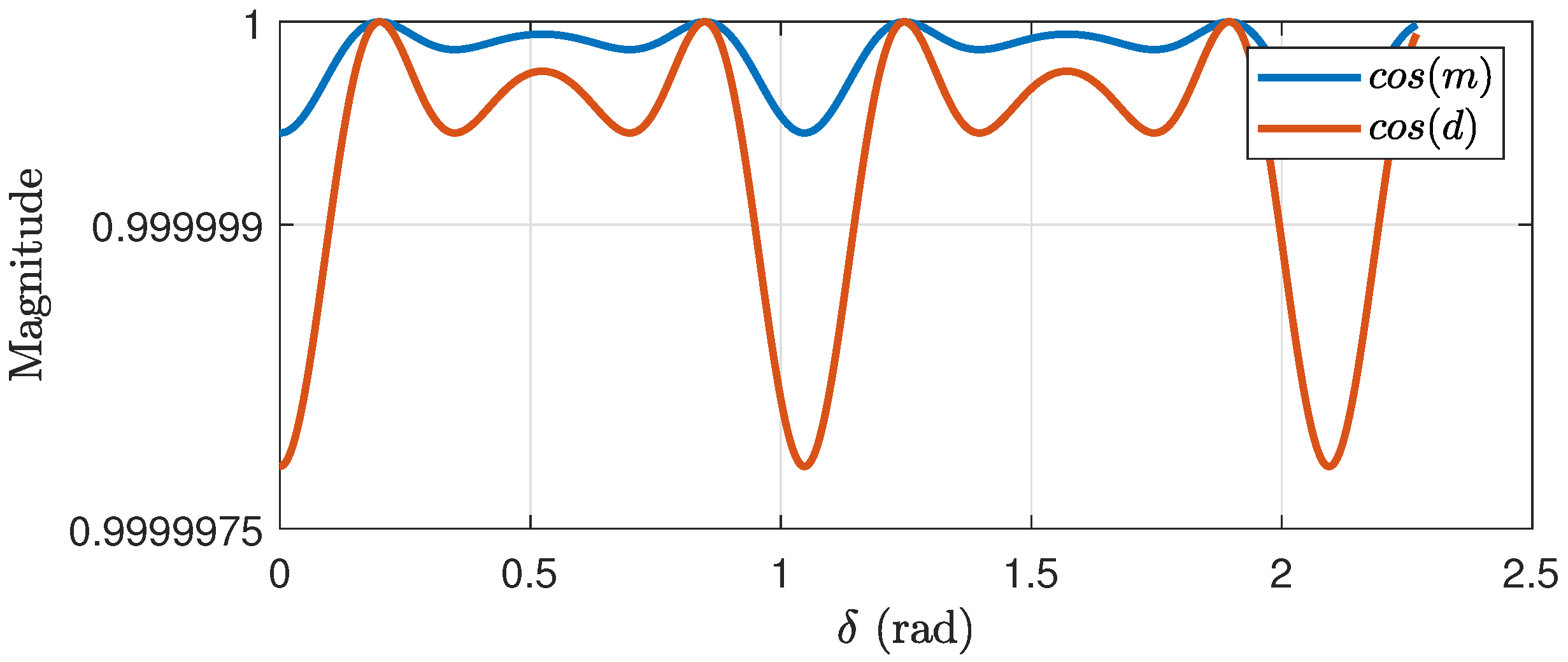
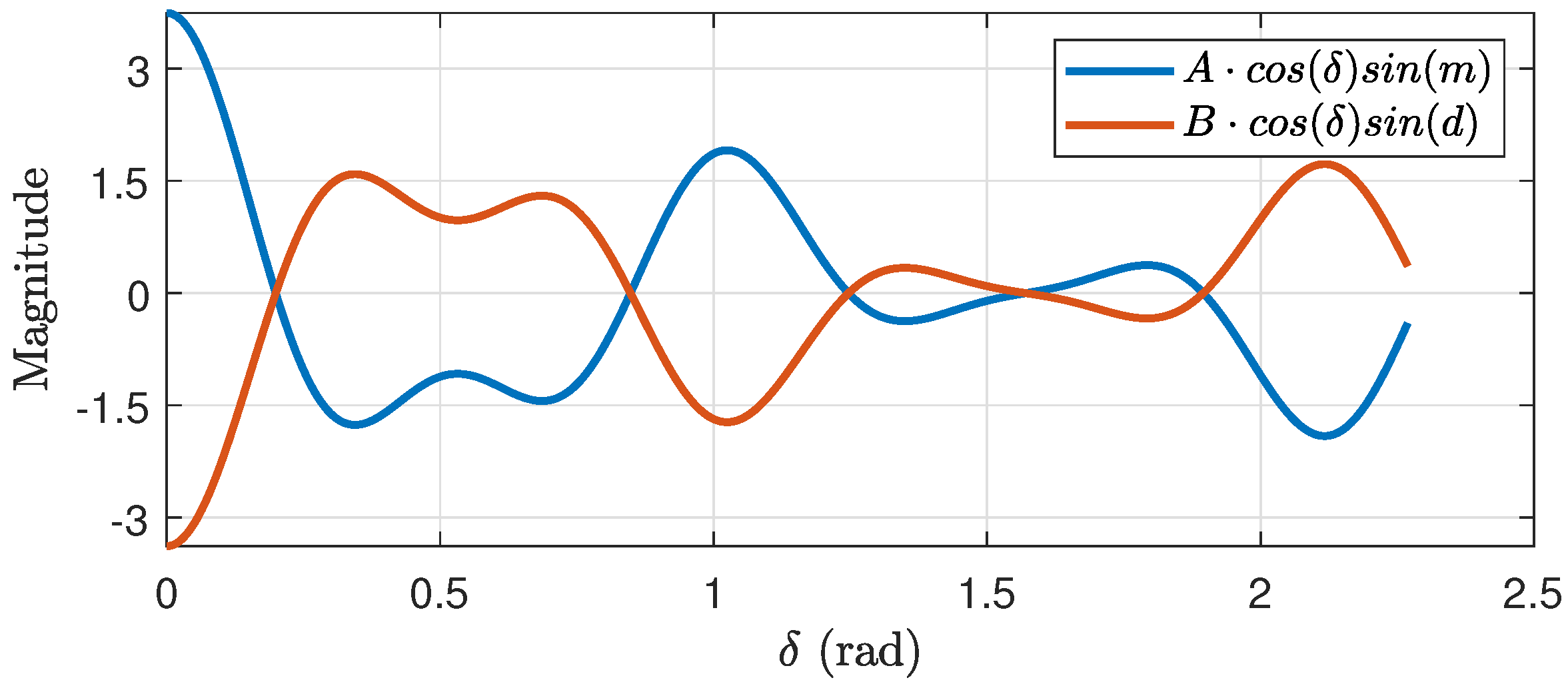
To investigate the response of the torque comparator to fault presence in DTC-driven PMSM, the multiplication terms and offset terms on the torque signal given in (18) and (19) are studied. The multiplication terms are and and they are shown in Figure 16. It can be observed that their effect on and is negligible, as their magnitude is near unity.
The offset terms and are shown in Figure 17. It can be noticed that these terms mostly offset each other and, hence, their overall effect on the torque is negligible, as depicted in Figure 17.
In summary, the DTC drive has the capability to incorporate the 6th and 12th harmonics in the torque angle instead of the torque signal itself. Although these additional harmonics are present, they have a negligible impact on the torque signal. As a result, the DTC drive can maintain the torque error within the torque hysteresis bands. This nonlinear behavior of the torque hysteresis comparator justifies the compensation of the second term of dynamic torque error in (8) due to the fault presence through the manipulation of the torque angle.
6. Conclusions
The impact of various faults on the performance of DTC-driven PMSMs has been studied. Four types of faults were studied: TTSC, HRC, partial demagnetization, and static eccentricity. An analytical description of the stator current behavior under faulty conditions was used to evaluate the response of the flux and torque hysteresis comparators. Faults introduce negative sequence components in the stator current that impact flux linkage estimation. The presence of the fault also introduces (1) a DC offset and (2) a double frequency component in the torque. The flux comparator adjusts the applied voltage vector to maintain the desired flux linkage by applying a negative sequence voltage to compensate for the fault effect. However, the negative sequence voltage applied to correct the error due to the fault is limited by the flux hysteresis bandwidth. If the bandwidth for the flux comparator is adequate, the DC offset and a portion of the double frequency component of the torque will be suppressed. The torque comparator manipulates the torque angle to keep the machine torque within the specified hysteresis bands.
Initially, it may seem advantageous for DTC to compensate for the flux linkage and torque errors introduced by the presence of the fault. However, excessive variations in the torque angle and unmodeled dynamics may lead to instability. Ideally, the torque angle should remain relatively constant to maintain synchronization between the stator and rotor flux linkage vectors. Additionally, violations of (20) due to the presence of the fault may cause the controller to become unstable.
As shown in Figure 12, Figure 13 and Figure 14, low severity faults result in minimal changes to the negative sequence component of the voltage. As the fault severity increases, the negative sequence component of the voltage increases. As long as the flux comparator is able to keep the flux within the specified hysteresis bands, the torque angle variations are minimal. Moreover, it is observed that the impact of the static eccentricity fault on overall drive operation is minimal compared to other faults. This indicates that the flux and torque hysteresis comparators employed in DTC can also mask the impact of faults. Therefore, the compensatory nature of DTC necessitates the development of fault detection and separation techniques that are suitable for the DTC structure to deploy mitigation schemes and maintain stability in the drive system. The results of this work are as follows:
- (1)
- Provided insight into the DTC reaction to faulty operation of a PMSM; and
- (2)
- Identified challenges in stability for DTC-driven PMSMs.
Future research should, therefore, focus on other factors that may affect fault detectability, such as the controller bandwidth, machine saturation level and sampling frequency.
Author Contributions
Conceptualization, I.M.A. and S.N.F.; methodology, I.M.A.; software, I.M.A.; validation, I.M.A.; formal analysis, I.M.A.; investigation, I.M.A.; resources, S.N.F.; data curation, I.M.A.; writing—original draft preparation, I.M.A.; writing—review and editing, S.N.F.; visualization, I.M.A.; supervision, S.N.F. All authors have read and agreed to the published version of the manuscript.
Funding
This work was partially funded by Michigan State University (MSU), USA, and the Jordan University of Science and Technology (JUST), Jordan. The APC was funded by Michigan State University (MSU).
Data Availability Statement
Data will be made available on request.
Acknowledgments
Ibrahim M. Allafi sincerely appreciates the Jordan University of Science and Technology (JUST) for sponsoring his graduate studies.
Conflicts of Interest
The authors declare no conflict of interest.
Abbreviations
The following abbreviations are used in this manuscript:
| DTC | Direct Torque Control |
| FEM | Finite Element Model |
| FFT | Fast Fourier Transform |
| FOC | Field-Oriented Control |
| HRC | High Resistance Contact |
| PMSM | Permanent Magnet Synchronous Machine |
| TTSC | Turn-to-Turn Short Circuit |
| ZSVC | Zero-Sequence Voltage Component |
References
- Thangavel, S.; Mohanraj, D.; Girijaprasanna, T.; Raju, S.; Dhanamjayulu, C.; Muyeen, S.M. A Comprehensive Review on Electric Vehicle: Battery Management System, Charging Station, Traction Motors. IEEE Access 2023, 11, 20994–21019. [Google Scholar] [CrossRef]
- González-Cagigal, M.A.; Rosendo-Macías, J.A.; Gómez-Expósito, A. Parameter Estimation of Wind Turbines With PMSM Using Cubature Kalman Filters. IEEE Trans. Power Syst. 2020, 35, 1796–1804. [Google Scholar] [CrossRef]
- Wang, W.; Liu, C.; Zhao, H.; Song, Z. Improved Deadbeat-Direct Torque and Flux Control for PMSM With Less Computation and Enhanced Robustness. IEEE Trans. Ind. Electron. 2023, 70, 2254–2263. [Google Scholar] [CrossRef]
- Allafi, I.M.; Foster, S.N. Condition Monitoring Accuracy in Inverter-Driven Permanent Magnet Synchronous Machines Based on Motor Voltage Signature Analysis. Energies 2023, 16, 1477. [Google Scholar] [CrossRef]
- Bhuiyan, E.A.; Akhand, M.M.A.; Das, S.K.; Ali, M.F.; Tasneem, Z.; Islam, M.R.; Saha, D.K.; Badal, F.R.; Ahamed, M.H.; Moyeen, S.I. A Survey on Fault Diagnosis and Fault Tolerant Methodologies for Permanent Magnet Synchronous Machines. Int. J. Autom. Comput. 2020, 17, 763–787. [Google Scholar] [CrossRef]
- Kadjoudj, M.; Golea, N.; Benbouzid, M. Problems of Stator Flux Estimation in DTC of PMSM Drives. J. Electr. Eng. Technol. 2007, 2, 468–477. [Google Scholar] [CrossRef]
- Feng, C.; Chaoying, X.; Xiaoxin, H. Study on the losing control problem of direct torque control in permanent magnet synchronous motor drive. Trans. Inst. Meas. Control 2019, 41, 504–515. [Google Scholar] [CrossRef]
- Haddad, R.Z.; Strangas, E.G. On the Accuracy of Fault Detection and Separation in Permanent Magnet Synchronous Machines Using MCSA/MVSA and LDA. IEEE Trans. Energy Convers. 2016, 31, 924–934. [Google Scholar] [CrossRef]
- Haddad, R.Z.; Lopez, C.A.; Foster, S.N.; Strangas, E.G. A Voltage-Based Approach for Fault Detection and Separation in Permanent Magnet Synchronous Machines. IEEE Trans. Ind. Appl. 2017, 53, 5305–5314. [Google Scholar] [CrossRef]
- Zanardelli, W.G.; Strangas, E.G.; Aviyente, S. Identification of Intermittent Electrical and Mechanical Faults in Permanent-Magnet AC Drives Based on Time–Frequency Analysis. IEEE Trans. Ind. Appl. 2007, 43, 971–980. [Google Scholar] [CrossRef]
- Chen, H.; He, J.; Guan, X.; Demerdash, N.A.O.; EL-Refaie, A.M.; Lee, C.H.T. High-Resistance Connection Diagnosis in Five-Phase PMSMs Based on the Method of Magnetic Field Pendulous Oscillation and Symmetrical Components. IEEE Trans. Ind. Electron. 2022, 69, 2288–2299. [Google Scholar] [CrossRef]
- Ebrahimi, B.M.; Faiz, J. Feature Extraction for Short-Circuit Fault Detection in Permanent-Magnet Synchronous Motors Using Stator-Current Monitoring. IEEE Trans. Power Electron. 2010, 25, 2673–2682. [Google Scholar] [CrossRef]
- Ebrahimi, B.M.; Faiz, J.; Roshtkhari, M.J. Static-, Dynamic-, and Mixed-Eccentricity Fault Diagnoses in Permanent-Magnet Synchronous Motors. IEEE Trans. Ind. Electron. 2009, 56, 4727–4739. [Google Scholar] [CrossRef]
- Wang, B.; Wang, J.; Griffo, A.; Sen, B. Stator Turn Fault Detection by Second Harmonic in Instantaneous Power for a Triple-Redundant Fault-Tolerant PM Drive. IEEE Trans. Ind. Electron. 2018, 65, 7279–7289. [Google Scholar] [CrossRef]
- Allafi, I.M.; Foster, S.N. Fault Detection and Identification for Inverter-Driven Permanent Magnet Synchronous Machines. In Proceedings of the 2021 IEEE 13th International Symposium on Diagnostics for Electrical Machines, Power Electronics and Drives (SDEMPED), Dallas, TX, USA, 22–25 August 2021; Volume 1, pp. 358–364. [Google Scholar] [CrossRef]
- Hang, J.; Ding, S.; Ren, X.; Hu, Q.; Huang, Y.; Hua, W.; Wang, Q. Integration of Interturn Fault Diagnosis and Torque Ripple Minimization Control for Direct-Torque-Controlled SPMSM Drive System. IEEE Trans. Power Electron. 2021, 36, 11124–11134. [Google Scholar] [CrossRef]
- Hang, J.; Wu, H.; Ding, S.; Hua, W.; Wang, Q. A DC-Flux-Injection Method for Fault Diagnosis of High-Resistance Connection in Direct-Torque-Controlled PMSM Drive System. IEEE Trans. Power Electron. 2020, 35, 3029–3042. [Google Scholar] [CrossRef]
- Allafi, I.M.; Foster, S.N. On the Accuracy of Frequency Based Fault Diagnosis for DTC-driven PMSM. In Proceedings of the 2022 International Conference on Electrical Machines (ICEM), Valencia, Spain, 5–8 September 2022; pp. 1628–1634. [Google Scholar] [CrossRef]
- Allafi, I.M.; Foster, S.N. Condition Monitoring of Direct Torque Controlled Permanent Magnet Synchronous Machines. In Proceedings of the 2022 IEEE Energy Conversion Congress and Exposition (ECCE), Detroit, MI, USA, 9–13 October 2022; pp. 1–7. [Google Scholar] [CrossRef]
- Hadef, M.; Djerdir, A.; Mekideche, M.R.; N’Diaye, A.O. Diagnosis of stator winding short circuit faults in a direct torque controlled interior permanent magnet synchronous motor. In Proceedings of the 2011 IEEE Vehicle Power and Propulsion Conference, Chicago, IL, USA, 6–9 September 2011; pp. 1–8. [Google Scholar] [CrossRef]
- Teng, Q.; Zhu, J.; Wang, T.; Lei, G. Fault tolerant direct torque control of three-phase permanent magnet synchronous motors. WSEAS Trans. Syst. 2012, 11, 465–476. [Google Scholar]
- Son, D.I.; Han, J.S.; Park, J.S.; Lim, H.S.; Lee, G.H. Performance Improvement of DTC-SVM of PMSM with Compensation for the Dead Time Effect and Power Switch Loss Based on Extended Kalman Filter. Electronics 2023, 12, 966. [Google Scholar] [CrossRef]
- Rahman, M.; Zhong, L.; Hu, W.; Lim, K.; Rahman, M. An investigation of direct and indirect torque controllers for PM synchronous motor drives. In Proceedings of the Second International Conference on Power Electronics and Drive Systems, Singapore, 26–29 May 1997; Volume 2, pp. 519–523. [Google Scholar] [CrossRef]
- Ojaghi, M.; Faiz, J. An experimental/simulation investigation to mixed eccentricity fault diagnosis of induction motors under DTC. In Proceedings of the 2014 IEEE International Conference on Industrial Technology (ICIT), Busan, Republic of Korea, 26 February–1 March 2014; pp. 143–148. [Google Scholar] [CrossRef]
- Cruz, S.; Cardoso, A. Diagnosis of stator inter-turn short circuits in DTC induction motor drives. IEEE Trans. Ind. Appl. 2004, 40, 1349–1360. [Google Scholar] [CrossRef]
- Berzoy, A.; Mohammed, O.A.; Restrepo, J. Analysis of the Impact of Stator Interturn Short-Circuit Faults on Induction Machines Driven by Direct Torque Control. IEEE Trans. Energy Convers. 2018, 33, 1463–1474. [Google Scholar] [CrossRef]
- Niu, F.; Wang, B.; Babel, A.S.; Li, K.; Strangas, E.G. Comparative Evaluation of Direct Torque Control Strategies for Permanent Magnet Synchronous Machines. IEEE Trans. Power Electron. 2016, 31, 1408–1424. [Google Scholar] [CrossRef]
- Alsofyani, I.M.; Idris, N.R.N.; Lee, K.B. Dynamic Hysteresis Torque Band for Improving the Performance of Lookup-Table-Based DTC of Induction Machines. IEEE Trans. Power Electron. 2018, 33, 7959–7970. [Google Scholar] [CrossRef]
- Mathapati, S.; Bocker, J. Analytical and Offline Approach to Select Optimal Hysteresis Bands of DTC for PMSM. IEEE Trans. Ind. Electron. 2013, 60, 885–895. [Google Scholar] [CrossRef]
- Chen, X.; Hu, J.; Chen, K.; Peng, Z. Modeling of electromagnetic torque considering saturation and magnetic field harmonics in permanent magnet synchronous motor for HEV. Simul. Model. Pract. Theory 2016, 66, 212–225. [Google Scholar] [CrossRef]
- Zhong, L.; Rahman, M.; Hu, W.; Lim, K. Analysis of direct torque control in permanent magnet synchronous motor drives. IEEE Trans. Power Electron. 1997, 12, 528–536. [Google Scholar] [CrossRef]
Figure 1.
Electromagnetic torque and stator flux linkage control loops in DTC-driven PMSM.

Figure 2.
Torque and stator flux linkage variations due to hysteresis comparators. (a) Actual torque variation within torque hysteresis bands. (b) Actual flux variation within flux hysteresis bands.
Figure 2.
Torque and stator flux linkage variations due to hysteresis comparators. (a) Actual torque variation within torque hysteresis bands. (b) Actual flux variation within flux hysteresis bands.

Figure 3.
Frequency spectrum of the IPMSM torque magnitude under both FOC (left) and DTC (right) drives. The 6th and 12th harmonics are not observed in the DTC drive.
Figure 3.
Frequency spectrum of the IPMSM torque magnitude under both FOC (left) and DTC (right) drives. The 6th and 12th harmonics are not observed in the DTC drive.

Figure 4.
Frequency spectrum of the torque angle in DTC-driven PMSM.

Figure 5.
Sector partitions and the available set of voltage vectors in the DTC drive.

Figure 6.
Illustration of the error between the actual and estimated stator flux linkages after the occurrence of a fault.
Figure 6.
Illustration of the error between the actual and estimated stator flux linkages after the occurrence of a fault.

Figure 7.
Path of the estimated stator flux linkage based on the voltage vector selection table shown in Table 1.
Figure 7.
Path of the estimated stator flux linkage based on the voltage vector selection table shown in Table 1.

Figure 8.
Optimal path of the actual stator flux linkage based on the voltage vector selection table shown in Table 1.
Figure 8.
Optimal path of the actual stator flux linkage based on the voltage vector selection table shown in Table 1.

Figure 9.
Path of the actual stator flux linkage based on the voltage vector selection table shown in Table 1.
Figure 9.
Path of the actual stator flux linkage based on the voltage vector selection table shown in Table 1.

Figure 10.
Machine model in MAXWELL coupled with DTC circuit in SIMPLORER including the TTSC fault circuit on phase A winding.
Figure 10.
Machine model in MAXWELL coupled with DTC circuit in SIMPLORER including the TTSC fault circuit on phase A winding.

Figure 11.
Sequence components of the commanded voltages in DTC-driven PMSM under healthy operating conditions.
Figure 11.
Sequence components of the commanded voltages in DTC-driven PMSM under healthy operating conditions.

Figure 12.
Sequence components of the commanded voltages in DTC-driven PMSM under TTSC fault with different severity levels. The healthy sequence components, from Figure 11, are shown in the faded color. (a) Case 1: (15, 0.5 ). (b) Case 2: (30, 0.25 ).
Figure 12.
Sequence components of the commanded voltages in DTC-driven PMSM under TTSC fault with different severity levels. The healthy sequence components, from Figure 11, are shown in the faded color. (a) Case 1: (15, 0.5 ). (b) Case 2: (30, 0.25 ).

Figure 13.
Sequence components of the commanded voltages in DTC-driven PMSM under HRC fault with different severity levels. The healthy sequence components, from Figure 11, are shown in the faded color. (a) Case 1: 100%. (b) Case 2: 150%.
Figure 13.
Sequence components of the commanded voltages in DTC-driven PMSM under HRC fault with different severity levels. The healthy sequence components, from Figure 11, are shown in the faded color. (a) Case 1: 100%. (b) Case 2: 150%.

Figure 14.
Sequence components of the commanded voltages in DTC-driven PMSM under demagnetization fault with different severity levels. The healthy sequence components, from Figure 11, are shown in the faded color. (a) Case 1: 1 Magnet. (b) Case 2: 3 Magnets.
Figure 14.
Sequence components of the commanded voltages in DTC-driven PMSM under demagnetization fault with different severity levels. The healthy sequence components, from Figure 11, are shown in the faded color. (a) Case 1: 1 Magnet. (b) Case 2: 3 Magnets.

Figure 15.
Sequence components of the commanded voltages in DTC-driven PMSM under eccentricity fault with different severity levels. The healthy sequence components, from Figure 11, are shown in the faded color. (a) Case 1: 40%. (b) Case 2: 60%.
Figure 15.
Sequence components of the commanded voltages in DTC-driven PMSM under eccentricity fault with different severity levels. The healthy sequence components, from Figure 11, are shown in the faded color. (a) Case 1: 40%. (b) Case 2: 60%.

Figure 16.
The magnitude of the magnet and reluctance torque multipliers, cos (m) and cos (d), in (18) and (19).


Table 1.
Voltage vector selection table used in DTC-driven PMSM.
| Sector | |||||||
|---|---|---|---|---|---|---|---|
Table 2.
Specifications for the IPMSM used in the co-simulation.
| Parameter | Value |
|---|---|
| Rated power | 3.8 kW |
| Rated RMS phase current | 18 A |
| Rated RMS line voltage | 480 V |
| Phases/Poles/Slots | 3/10/12 |
| Turns per slot | 150 |
| Phase resistance | 2 |
| Magnet flux linkage | 0.287 Wb |
| Residual flux density | 1.2 T |
| Air gap length | 1 mm |
Table 3.
Settings of the DTC-Driven PMSM.
| Controller Settings | Symbol | Value |
|---|---|---|
| Flux hysteresis band | ||
| Torque hysteresis band | ||
| Sampling frequency | 25 s | |
| Initial conditions | () | (0.287, 0) Wb |
| Operating points | () | Nm, Wb) |
Table 4.
Severity levels of the studied faults.
| Fault Type | Severity | Value |
|---|---|---|
| TTSC | () | (15, 0.5 ) |
| (30, 0.25 ) | ||
| HRC | () | 100% |
| 150% | ||
| Partial Demagnetization | Number of Affected Magnets | 1 Magnet |
| 3 Magnets | ||
| Static Eccentricity | () | 40% |
| 60% |
Disclaimer/Publisher’s Note: The statements, opinions and data contained in all publications are solely those of the individual author(s) and contributor(s) and not of MDPI and/or the editor(s). MDPI and/or the editor(s) disclaim responsibility for any injury to people or property resulting from any ideas, methods, instructions or products referred to in the content. |
© 2023 by the authors. Licensee MDPI, Basel, Switzerland. This article is an open access article distributed under the terms and conditions of the Creative Commons Attribution (CC BY) license (https://creativecommons.org/licenses/by/4.0/).
Share and Cite
MDPI and ACS Style
Allafi, I.M.; Foster, S.N. Analysis of Direct Torque Control Response to Stator and Rotor Faults in Permanent Magnet Synchronous Machines. Energies 2023, 16, 6940. https://0-doi-org.brum.beds.ac.uk/10.3390/en16196940
AMA Style
Allafi IM, Foster SN. Analysis of Direct Torque Control Response to Stator and Rotor Faults in Permanent Magnet Synchronous Machines. Energies. 2023; 16(19):6940. https://0-doi-org.brum.beds.ac.uk/10.3390/en16196940
Chicago/Turabian StyleAllafi, Ibrahim M., and Shanelle N. Foster. 2023. "Analysis of Direct Torque Control Response to Stator and Rotor Faults in Permanent Magnet Synchronous Machines" Energies 16, no. 19: 6940. https://0-doi-org.brum.beds.ac.uk/10.3390/en16196940
Note that from the first issue of 2016, this journal uses article numbers instead of page numbers. See further details here.