3. Technical and Functional Properties of Fuse-Links
The reliability of technical objects (which is a separate scientific domain) considers fuse-links to be an anti-damage subsystem (alternatively dubbed as anti-failure) [
38,
39,
40]. Solutions that directly precede its tripping are, above all, shielding and intervention subsystems [
41,
42,
43,
44]. This means that fuses treated as a subsystem, which constitutes the final link of a system responding to failure phenomena, are somewhat the “last resort”, which is triggered only when other measures fail to achieve the intended outcomes or their operational range is exhausted. In reality, a triggered anti-damage system in an overwhelming majority of cases means the occurrence of permanent damage to electronic devices, the mitigation of which is the role of, among others, safety fuses. It should be noted that a decision on using anti-failure subsystems (represented, among others, by fuse-links) is choosing a certain “technical philosophy”, the outcomes of which, depending on the decision, will be associated with a partial damage or, in extreme cases, a damage that fully incapacitates the operation of a given object (with an occurrence that should be treated as probable). On the other hand, the decision leaves space for catastrophic failures, the consequences of which can be, in many cases, far more costly than the expenses incurred in relation to the use of anti-damage systems. These consequences are often directly related to the threat to property and people (e.g., in the form of an electrical shock hazard or a fire risk).
When considering the characterized subassemblies from the perspective of the theory of circuits (shared by electronics and electrical engineering), their task is to protect a circuit they are used in against the outcomes of potential short circuits or overload current. The listed phenomena are almost always a manifestation of an existing failure, frequently triggered by commutation processes (leading to a transient state within a circuit) or processes not included in the technical data of a given system, such as overloaded devices. The aforementioned objective is achieved by disconnecting an electrical circuit at one or more modules of a given electronic device, which obtains its limit condition in a situation of a deliberate, complete isolation of electricity. There are a number of arguments for the use of safety fuses in electronic devices. These include, for example, low cost (per single subassembly) of a fuse-link, the replacement process of which is very simple and basically involves typical safety procedures applicable to the operation of electronic and electrotechnical devices. An unavoidable advantage of the discussed solutions is their very simple structure.
All the aforementioned advantages become more evident when the operation principle of the analysed components is considered more closely. Under typical operating conditions (under which the protected circuit experiences only current of an intensity lower or equal to the load current value), a fuse behaves like a normal conductor that connects individual elements of electrical and electronic circuits, which in practical embodiments is in the form of cables, conduits or printed circuits on PCBs (printed circuit board). The only difference is that a fuse reflects its very short section and, most importantly, is subject to replacement. In the event of one of the aforementioned failure phenomena occurring within an electrical circuit, the outcomes of which come in the form of a current flow at an overcurrent value, the most important fuse element—a fuse-link fibre—is disintegrated through melting. As a result, an opening appears in the circuit, with its position isolating electricity in its fragment or, in an extreme case, the entire electronic device. This process is called circuit breaking and is aimed at preventing the flow of current with a hard-to-control intensity in such a situation. The described mechanisms are based on the physics of electric current flow through a conductor, which inherently entails energy losses, represented by the release of Joule heat within such a material, the value of which in DC circuits can be determined based on the equation below (in the case of miniature fuse-links, the presented description is appropriate for the range of load currents):
where:
Resistance can be expressed in a more precise way. This requires taking into account material properties and geometric dimensions of the conductor:
where:
To a certain extent, the fuse is a specific variant of a conductor, or to be more precise, this is the function implemented by its fuse-link fibre. In the course of R&D work, the manufacturers of the subassembly group in question select physical parameters of the fuse-link fibre so that when current of an intensity lower or equal to the arbitrarily adopted load current value flows through it, and the associated Joule heat is released, it is not melted or permanently deformed (also vaporized in extreme cases). It should be emphasized that the said characteristic current value is one of the most important design parameters of the analysed elements. Resistivity expressed by Formula (2) is a value strongly correlated with the material used in the manufacturing of safety fuse fuse-links. Steel, copper and nickel are most frequently used for this purpose; gold and silver are less common. These are mainly alloys of certain metals above; their proportions, however, are in most cases covered by trade secrets. A more common practice is the use of ordinary metal alloys as fuse element core material, with thin noble metal layers galvanically applied or sprayed onto it. Two essential arguments advocate this action. The first relates to the fact that noble metal films constitute good protection against weather conditions and the associated processes of corrosion and oxidation. The second is associated with the economic aspect. It is much cheaper to spray a thin noble metal layer on a fuse element than to have the entire fibre made of them (which is the case in particularly critical applications). Safety fuses, just like most modern electronic subassemblies, are subject to standardization, also in terms of dimensions. In the case of this article, the analysis will cover only 20-mm long glass fuses. For natural reasons, it is a dimension that simultaneously determines the minimum length of a fuse-link fibre, which can be used in a fuse with such a base. In order to achieve the required fuse parameters, their manufacturers modify both the fuse element shape (creating spirals or forming its shape, so that it resembles a triangular course in order to extend its effective length, and to utilize certain mechanical benefits of such a solution) and diameter, which in typical fuses ranges from 0.01 to 0.5 mm. However, it should be stressed that improper selection of the aforementioned parameters or a technical impossibility of maintaining their stability (e.g., diameter throughout the entire fibre length, fuse wire composition, etc.) will have a tangible impact on the circuit breaking time tw of such a fuse-link.
Given Equations (1) and (2), and assuming a perfectly homogeneous and round fuse-link fibre cross-section throughout its entire length, one can obtain an expression that comprehensively describes the Joule heat released therein during the normal operation of the component (range of load currents), described through variables, most importantly from the perspective of electronics:
The description of the phenomena occurring in the fuse-link fibre during the occurrence of overcurrent is an extensive problem and is difficult to analyse mathematically. From the point of view of electrical circuits, the mentioned process is a transient state, the analysis of which is carried out using the operator calculus. It is also worth noting that when the circuit is switched off, the fuse-link fibre itself changes its resistance, undergoing a destructive process. This issue will not be analysed in detail in this study.
When analysing fuses in the context of electronic security systems (ESS), one cannot fail to notice their twofold responsibility. Primarily, these are elements of a protective nature (constituting an anti-failure subsystem), presented in detail in the previous section of this article. Their additional scope of responsibility becomes evident when they perform their function in such special systems as ESS (within the modules and component devices). The damage to any of the electronic system parts radically changes the discussion range. Almost the sole objective of ESSs is the widely understood protection of property that can be broken down into two essential groups. The first set includes all material goods, such as documents, cash, jewellery, precious metals, weapons, securities, etc. The next group is made up of values without a physical form. It can be represented by, for example, information, the direct theft of which is often impossible; however, to permit an intruder simply to study it briefly can often entail incurred losses. An example can be a medical database of an enterprise that aggregates sensitive data of its patients and is stored on servers. It can be assumed that such a repository would be characterized by a distributed data structure, which excludes its direct theft. But damage in this case will be caused already by the very copying of all or selected records by an unauthorized person who penetrates the premises of the enterprise. A very clear example of intangible goods entrusted to electronic security systems are the health and life of guests and personnel within an ESS-protected area. Certainly, hardly anyone will attempt to evaluate such goods. The comparison of the previously analysed case with the use of safety fuses in typical electronic devices representing the consumer solution sector would only show a significant disproportions of the potential failure consequences that could not have been prevented by a fuse-link.
From the perspective of technical sciences—operation, any failed or sluggish response of all protection subsystems (including anti-failure, represented by, among others, fuse-links) will almost tangibly impact the level of security provided by a specific security system, which should be constantly maintained throughout its entire operation process. The fuse-link response efficiency impacts the final outcomes directly impacting the operating states of an electronic security system. Their set may open one or many security hazard states of the protected property (in the field of reliability they are called the states of partial unfitness and are represented by, e.g., isolating power from at least one ESS device or module). In a limit case, it can lead to reaching the state of complete insecurity, the consequence of which may be significantly more far-reaching than in the previously discussed case, when despite considerable restrictions, there is a certain protection potential. The entire previous analysis leads to formulating an important conclusion. An appropriate ESS operation process is very important from the perspective of elements making up security systems. However, strategic importance lies with anti-failure subsystems, which ultimately determine whether the goods within the ESS detection zone are covered by any security measures at all, and if so, by what kind. This is why it is particularly important to focus on confronting the credibility of technical parameters in anti-failure subsystems (such as fuse-links) with reality. In principle, it is advisable for this approach to be applied to all devices and modules making up an ESS. Importantly, attempts at implementing such actions are already in progress. Examples include an analysis of response-resistive thresholds of detection lines (which are detection mains for intrusion and hold-up alarm systems) within a diverse climatic environment [
45]. Although this is an example of a practical verification of ESS function implementation correctness under variable conditions, it directly applies to its protection potential and fully falls in line with the presented philosophy.
When looking at safety fuses through the prism of ESS reliability and their possibly most reliable operation process, one of the most important parameters in this context is the circuit breaking time tw. Its significance becomes more evident when one learns the overload behaviour of an analysed element. As a rule of thumb, this process can be divided into two parts. The first stage lasts from the moment the current at an overcurrent value flows through a given fuse, which protects a given electric circuit section, causing energy losses in a fuse-link fibre represented by Joule heat, until its continuity is interrupted. It is called the pre-arcing time tp. However, bear in mind that this phenomenon does not mean the end of current flow within the protected circuit. The said process maintains an electric arc that is trying to “reconnect” the fuse-link fibre, the continuity of which has been interrupted through melting. The time counted from the moment of interrupting fuse element continuity until the electric arc disappears (resulting in total power decay in the branch protected by the fuse-link) is called the arcing time tp. As evident, breaking time tw is a parameter that enables an objective comparison and assessment of the operating effectiveness of the components by numerous manufacturers and operating as an anti-failure subsystem, analysed within this article. Please note that this will be the case when following the same methodology and using the same measuring instruments throughout the entire research process. Such a line of reasoning allows for a conclusion that the fuse breaking time tw enables a comprehensive assessment of its circuit breaking potential within a given application, without the need to take into account in detail the previously characterized partial processes, the length of which may impact numerous variables and unnecessarily complicate further analysis for this reason.
The characteristics of subassemblies and devices acting as an anti-failure subsystem sometimes involves the implementation of this task through self-destruction. This is the exact approach represented by fuse-links. The aforementioned property determines the need to acquire data on the protection potential of security elements in question through conducting practical tests of a destructive nature. It should be emphasized that it is a rather general type of experiment, and safety fuses additionally represent a particular group of devices and elements subject to such testing. When comparing fuse-links with, e.g., girders in production halls, one can notice that their strength properties are also studied through destructive testing. The difference is that the latter of these examples is not a security element itself but a structural part, without which a technical object of such type cannot exist. In the case of fuses, their application in most circuits of electronic and electrotechnical devices is voluntary. Importantly, regardless of whether a tested element belongs to one of the aforementioned groups, a certain significant and characteristic destructive testing features manifests itself—they are also conducted in relation to application where security is treated as an issue, with no room for any compromise at all. Destructive testing of turbofan engines used, among others, in passenger aircraft can be an example. The will to execute destructive testing entails a need to solve a number of engineering problems. It is necessary to prepare an appropriate experimental platform, so that its structure, in general, enables measuring a specific parameter while offering the researcher its guaranteed, correct recording each time within a given test. This stems from the fact that there is only one chance to study the protective properties of a given component or subassembly (selected, e.g., randomly) through a destructive test. Furthermore, due to the specificity of destructive testing, it is definitely advisable to develop such mechanisms and solutions within a measuring stand that ensure checking the correctness of its operation and settings of all used I&C, so as to prevent a situation wherein a test object is destroyed leading to the failure to obtain a measurement result for any of the tested fuse specimens during the actual test, and to eliminate the need to destroy them during the preparations. The last issue associated with implementing such research is the obligation to analyse measurement results within the statistics domain. This stems from a simple fact. Conducting a destructive test involving a given safety fuse unit provides full knowledge of its protective properties. However, it also irreversibly eliminates the need for its reuse. In a borderline case, to have certainty with respect to any larger set of elements (e.g., a specific manufacturing batch of a specific fuse-link model of a given manufacturer), this would paradoxically require destroying all units in such a batch, which is obviously fully unacceptable. Therefore, the protection potential of a certain subassembly population should be inferred based on the results of destructive tests covering a selected set of specimens that can be recognized as an objective representation of this component population.
4. Materials and Methods
In order to assess the protective properties of fuse-links, the authors designed an experimental stand that enables meeting all previously listed requirements. It is composed of the following recording and measuring instruments:
RIGOL DS1102E (Beijing, China) two-channel digital oscilloscope;
MCP (Shanghai MCP Corp.), (Shanghai, China) stabilized laboratory, continuous AC power supply, model designation M10-QS3020;
DC [
46,
47] experimental add-on, designed and constructed at the Institute of Electronic Systems of the Military University of Technology (Warsaw, Poland);
MLN 100/1 cables by Hirschmann (SKS Kontakttechnik GmbH), (Niederdorf, Germany) acting as a measuring add-on device power supply line.
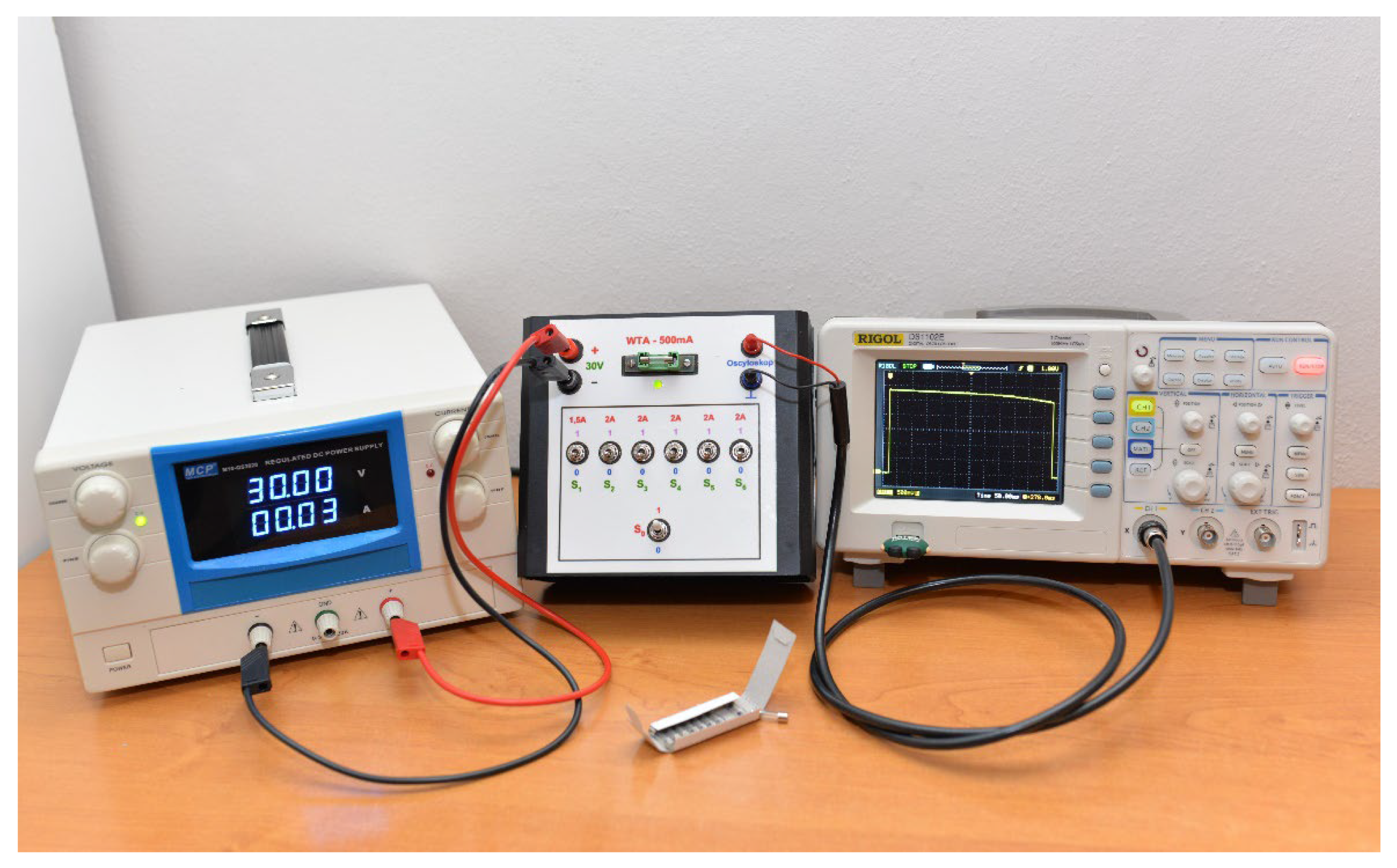
Figure 1 shows the appearance of the described test kit. An adjustable power supply generating maximum DC voltage of 30 [V] and 20 [A] was used to power the passive measuring attachment and secure adequate current reserve required by the aforementioned module to generate test currents of desired intensity values. Greatly simplifying, the constructed add-on can be deemed as a semi-conductor current source, the output of which via a coupled fuse base was connected in series with a group of high-capacity resistors (connected in parallel), individually hooked into the circuit with toggle switches marked successively from S1 to S6. Resistor values were selected to induce the flow of overload current with specific, discrete intensity after adding some of them to the circuit. For the sake of precision, it should be added that the add-on has one resistor inducing 1.5 [A] current and five resistors, each inducing the flow of a 2 Amp current. When analysing all possible combinations of toggle switch settings, it is easy to predict that the add-on offers generating a test current with an intensity ranging from 1.5 [A] to 11.5 [A] (both-sided included) with selected discrete values. All the variants are included in Table 2. In order to illustrate the operation of the developed add-on device for destructive testing, let us assume that the objective is to induce a 7.5 [A] current flow through the tested fuse. This requires using the S1 switch to add the 1.5 [A] current-inducing resistor and any of the other switches (e.g., S2 to S4) to add the resistors inducing the 2 [A] current flow. The entire resistive load system is added through changing the S0 switch position and is aimed at ensuring controlled and intentional destructive testing activation. Simultaneously, the combined holder based of the tested safety fuse is connected to a system for the visual verification of fuse-link activation, based on a LED
(Light Emitting Diode). The voltage signal from a given fuse-link is recorded with a digital oscilloscope (the time base generator of which operates in single mode) via a resistive voltage divider connected in parallel to the combined fuse base circuit (created by 1.1 [kΩ] and 9.1 [kΩ] resistors). The oscilloscope probe (in the form of a banana-BNC cable) collects the signal from the former.
The decision on safety fuse destructive testing using excitations of DC nature was determined by the fact that a majority of modules and devices making up electronic security systems is powered with DC voltage; therefore, fuse links in this system group primarily protect circuits of exactly such a nature. Examples of such ESS components include gel battery charging systems (acting as emergency power sources within the systems in questions) and relay modules. Essentially, an exception to this rule in the ESS industry can be power supplies (mainly transformer-based, both in the form of stand-alone devices, as well as modules/circuits separated within an integrated device).
Fuse link series of almost all manufacturers operating in Poland were qualified for destructive testing. They are characterized by the following parameters:
type: miniature;
dimensions (diameter × length): 5 × 20 [mm];
body material: glass;
filler type: none—no quenching agent (lower breaking capacity);
operating characteristics: quick-acting;
rated current: 500 [mA].
Fast-acting safety fuses are often used to protect semi-conductor elements particularly sensitive to overload and short-circuits, which are widely utilized in modern electronic devices. Examples of such components include microprocessors, MOSFET (Metal-Oxide Semiconductor Field-Effect Transistor) transistors, diodes, thyristors, etc. Fuses, the bodies of which are characterized by the aforementioned dimensions, are still some of the most commonly used types in electronic devices in Europe and also the United States.
The tests also Involved safety fu”es o’ almost all manufacturers and brands available in Poland. These included products by:
ESKA Erich Schweizer GmbH (Kassel, Germany), model: 520.614 (product family 520.600);
SIBA GmbH (Lünen, Germany), model: 179020;
Schurter Holding AG (Luzern, Switzerland), series: FSF, model: 0034.1513;
Littelfuse, Inc. (Chicago, IL, USA), series: 217, variant: 0217.500HXP.
The tested subassemblies also included these represented only by their importers and brands created by them. However, the information with respect to the original manufacturing plants, except for the country of origin—People’s Republic of China—are unknown. They include:
fuses distributed in Poland under the BLOW brand, owned by Prolech sp. j. from Garwolin;
fuses of an unknown brand, with a model designation LX3029 0.5 A, distributed in Poland by Lamex with its seat in Lipówki.
In both of the cases above efforts were made to obtain a product data sheet and determine the original product manufacturer. To this end, the distributors of these subassemblies were contacted by e-mail. Unfortunately, none of the aforementioned information had been received until the date of submitting this article.
Figure 2 shows all studied components.
Such a large variety of fuse-link manufacturers, reflecting almost an entire range of these products available in Poland, while exhibiting the same, most important technical parameters will allow, in the course of implementing studies aimed at comparing their protective abilities while using identical instruments and measurement methodology, to objectively determine whether all products guarantee the same operating effectiveness. It should be emphasized that, practically speaking, fuse-links marketed under brands created by their importers and distributors can constitute a certain unknown, since their volume on the market undergoes constant changes. In addition, it may turn out that two different importers can independently of each other import fuse-links of the same manufacturer, resulting in selling identical products, which differ only in terms of packaging graphics.
In order to conduct tests that are as universal as is feasible, it was impossible to distinguish a specific rated current value, which was statistically applied the most in modules and devices belonging to electronic security systems. It is always an individual issue and is strictly related to the wiring diagram, the characteristics of the circuit itself and the nature of forcing actions at which a given electronic device operates. For this reason, the authors decided to use fuses with a rated current of 500 [mA], since the testing current values provided by the measuring add-on are greater multiples of the adopted rated current.
Collecting subassemblies representing almost the entire product range available in Poland also automatically means that the tested elements will cover a diverse price range. Although unintentional, this is extremely useful. Completing destructive tests will enable determining whether the protective potential offered by the tested fuse-links and the unit price of such a component are correlated. If not, it will be necessary to indicate the most probable factors determining such a situation. The data required for the analysis is demonstrated in
Table 1.
5. Measurement Methodology, Results and Analysis
The research process can be divided into two parts. The first one was a preparatory stage that enabled appropriate configuration of the I&C instruments and its adequate testing. This guaranteed correct recording of the fuse-link breaking time tw, while simultaneously minimizing the risk that some measurements are not properly conducted during destructive testing, leading to meaningless test material losses. The power supply output voltage was set at 30.00 [V], and its maximum efficiency was declared via potentiometers in the current section of the device. The oscilloscope was configured as indicated below:
only the first device path active (recorded voltage signal found within the fuse-link using the measuring add-on);
channel gain 500 [mV/div];
position parameter at a level of: −1.5 [V];
time base trigger in single-mode tip;
leading-edge time base generator trip when the recorded signal level exceeds 1 [V];
time base value adapted as needed, depending on the expected breaking time of a given fuse-link (value optimized so that the recorded waveform fills the screen as much as possible);
the horizontal parameter marker located very near the left edge of the oscilloscope display.
As mentioned previously, the developed add-on is fitted with mechanisms that enable verifying the correct configuration of a measurement path, without the need for destructive testing that would not provide any measurement information. Its activation involved making sure that all toggle switches of the add-on were in the 0 position (open) and fastening a tested fuse to the combined base. The next step required moving the position of the S0 switch from 0 to 1, just to return to the starting position after a while. Such a configuration leads to a short-term flow of current with an intensity of approx. 0.02 [A] through the safety fuse. This was also the moment when the oscilloscope time base generator was triggered and the waveform of the voltage appearing on the test fuse-link began to be recorded. As one can easily guess, the device screen displayed a signal resembling a unit step.
The second part of the experiments comprised actual studies. Fuses by each of the manufacturers were subjected to tests according to the following guidelines:
drawing a set of eleven fuses from a package, to constitute the research subject;
checking circuit continuity in a given unit through the measuring add-on measurement path configuration correctness verification mode with support of the system for the visual verification of the LED fuse-link activation—in order to exclude a product manufacturing defect;
conducting a destructive test involving each unit of a safety fuse by a given manufacturer, using a different overcurrent value in each case (all values listed in
Table 2), with an identical configuration of toggle switches (e.g., in order to obtain an overcurrent of 4 [A], the S
2 and S
3 switches were always activated);
saving a digital version of the resultant waveform in a removable flash memory via appropriate options of the oscilloscope’s storage section;
measuring the breaking time tw of a given fuse-link using oscilloscope cursors.
Due to the rather surprising measurement results for BLOW fuses, the authors deviated from the previously characterised measurement methodology. Both issues are explained in more detail further in this article. Test results are shown in
Table 2, and their graphic form is illustrated in the form of time–current characteristics in
Figure 3. Three measurement series were conducted in the case of fuse-links distributed by Lamex.
The shape of obtained characteristics is consistent with theoretical knowledge. Furthermore, a noticeable, strongly decreasing breaking time value tw as a function of overcurrent in a great simplification is justified by the fact that the amount of Joule heat, which is the main factor causing fuse element disintegration in the fuse-link, increases proportionally to the square of the overcurrent flowing through it.
Concerning the analysis of the obtained measurement results, the results concerning the components marketed under the BLOW brand draw the most attention. The evident fact is that they are the product, which is characterized by the longest breaking times tw among all the tested fuse-links. Combined with the multitude of similar obtained properties, this finding can be overwhelming and somewhat camouflaging for the second of the encountered features. BLOW fuse-links would not isolate a circuit in the event of an overcurrent of both 1.5 [A] and 2.0 [A], which, from the point of view of ESS engineering, should be an immediate concern. As a result, a decision was made to deviate from the adopted research methodology when it came to these products. Prior to the actual destructive test, each of the eleven BLOW fuse-links was successively tested using overcurrents of intensities of 1.5 [A] and 2.0 [A] for five minutes at each of the respective values. The adopted time was determined by heat released in high-power resistors making up the load system of the test add-on, the further radiation of which resulted in the thermoplasticity of the said module’s casing plastic. Of course, the fibres were allowed to cool down between tests. The described experimental methodology modification was aimed at verifying whether such operation of the tested products was a one-time incident (due to, e.g., a manufacturing defect of a single unit) or their permanent feature. Consequently, the authors confirmed that each unit of the BLOW product did not isolate the circuit for overcurrents with intensities of 1.5 [A] and 2.0 [A] prior to the destructive test.
In the next step, the measurement results of fuse links distributed in Poland by Lamex were obtained. Relative to the results obtained for the subassemblies characterized above, the achieved breaking times were almost half as long. Three measurement series were conducted for these products. The graphical measurement representation in
Figure 2 enables a conclusion that all three time–current characteristics representing each of the series indicate good concentration of results.
A group of products exhibiting significantly shorter breaking times begins with products by the American Littelfuse, Inc. company and the German manufacturer ESKA Erich Schweizer GmbH, with a slight advantage of the components manufactured by the first of the enterprises, for overcurrents up to 3.5 [A], inclusive. In this scenario the breaking time ratio in relation to the tested fuse-links with the longest breaking times is variable, but in both cases, the worst coefficients (breaking time ratio of BLOW fuse-links related to the results for Littelfuse, Inc. and ESKA Erich Schweizer GmbH) of 8.64 and 9.05, respectively, were obtained for a current of 1.5 [A]. On the other hand, the most advantageous, also in both cases, was achieved for an overcurrent of 11.5 [A] and amounted to 6.35 and 4.91, respectively.
Ultimately, the set of products distinguished by the shortest breaking time of the circuit is opened by the products of Schurter Holding AG and SIBA GmbH. In this case, the authors of this publication are not attempting to indicate which of the products breaks the circuit faster, since the differences between measurement results for the components by these two companies in seven out of eleven tests fell within standard deviations. When comparing the results for BLOW products with components manufactured by Schurter Holding AG and SIBA GmbH, one can notice that the coefficients representing breaking time proportions for individual fuse-links are 14.92 (for a current of 1.5 [A] and 12.38 (for 6.0 [A]), respectively. On the other hand, the lowest proportionality coefficients, 10.31 and 10.41, respectively, were observed for the current with an intensity of 11.5 [A].
The conducted destructive testing series provided different breaking times for fuse-links of individual manufacturers (as evident, these differences were significant in certain cases). The natural action of every researcher in such a case should be an attempt to determine the sources behind these differences through eliminating them in the correct order. The first factor that should be excluded at the beginning is parameter discrepancy, which could be the result of conducting tests under different conditions—experimental environments, because all of the experiments were based on the same I&C instruments (moreover, the same units) and the identical measurement methodology was applied.
Next, the measurement uncertainty should be determined [
48], which is closely related to a specific measuring stand configuration used within the experiments. The above can be achieved based on two approaches. The first one is derived from the theory of error transfer, which is associated with measuring instrument uncertainties (mainly a digital oscilloscope in this case). The second approach describes the same issue through test result statistical analysis. The authors of this publication followed the second of the aforementioned philosophies, simultaneously assuming that the nature of occurring uncertainties is random (each time a different piece of fuse was tested). Because three time–current characteristics were developed for the products marketed in Poland by Lamex, they seem the best candidate for such an analysis. The only difference is that from that moment on, the perceptive perspective should be changed and they have to be treated in threefold (
N = 3) repeated fuse-link breaking tests in a given measurement session, for a specific overcurrent value. Therefore, all example calculations will utilize three measurements of the breaking time
tw exhibited by the fuse-links distributed by Lamex, for an overcurrent of 10.0 [A].
First, the authors determined the values of the best approximation
twnp of the
tw parameter based on three results of this value’s experimental measurements, best described by their arithmetic mean:
where:
—number of breaking time tw measurements for fuse-links of a given manufacturer, with the same overcurrent intensity value within a given measuring session;
—number of the i-th breaking time tw measurements for a specific fuse-link unit of a given manufacturer, with the same overcurrent intensity value within a given measuring session.
Absolute measurement uncertainty for each
i-th measurement treated separately (independently) is described by standard deviation
σtw. Because a measurement series consisted of only three measurements, the parameter below was calculated using the formula variant below, called the sample standard deviation:
where:
—number of breaking time tw measurements for fuse-links of a given manufacturer, with the same overcurrent intensity value within a given measuring session;
—number of the i-th breaking time tw measurements for a specific fuse-link unit of a given manufacturer, with the same overcurrent intensity value within a given measuring session;
—best approximation of the measured value twnp of the tw parameter in the form of an arithmetic mean N of its experimental measurement results.
As a result, the three measured breaking times
twzw (treated separately) can be presented as follows:
It was earlier determined that the best approximation of the measured breaking time
twnp was a measurement mean. Therefore, we are naturally interested in the uncertainty of exactly this result (which should naturally be influenced by the number of measurements taken in a series). It is represented by standard deviation of the mean. For similar reasons as in the case of Equation (5), let us apply the formula based on the sample standard deviation definition:
where:
—absolute measurement uncertainty of each i-th of the N completed measurements treated separately, expressed by a measure of standard deviation;
—number of breaking time tw measurements for fuse-links of a given manufacturer, with the same overcurrent intensity value within a given measuring session.
The obtained absolute uncertainty should be presented as a percentage of relative uncertainty:
where:
Ultimately, it should be concluded that the best approximation of the practically measured breaking time tw exhibited by fuse-links distributed by Lamex, for an overcurrent of 10.0 [A], is 18.80 [ms], with an uncertainty of 0.56 [ms], which amounts to 2.98% of the result. By implementing analogous considerations for all tested overcurrent values, the obtained relative percentage error would range from 1.20 to 6.75%. At the same time, it should be noted that in each case, the test would involve a different fuse unit; therefore, the aforementioned uncertainty range takes into account both the ones of random nature, as well as the manufacturing spread of tested components. In such a situation, one may be tempted to state that if a group of safety fuses from other manufacturers was subjected to the same number of measurement series, these tests would be characterized by similar uncertainties (or safer to say—not worse) obtained for individual overcurrent ranges.
Given the nature of actual measurements, the achieved uncertainty level proves their high accuracy, and, more important in this case, repeatability as well. As a result, from the perspective of applied test practice, a specific research and measurement instrumentation configuration should also be excluded as the source of high breaking time differences in fuse-links from individual manufacturers. Equation (7) explicitly indicates a possibility of further reduction in the values of obtained uncertainties (of course, within reason in the case of destructive tests) through conducting additional measurement series. It is also demonstrated by comparing Equations (6) and (7).
By means of elimination, all consideration up to this moment leads to a conclusion that differences in circuit breaking times tw in fuse-links from individual manufacturers result almost solely from the physical properties of individual products used therein— fuse-link fibres, to be more exact. In turn, factors that determine the properties of the said structural element have been more broadly characterized in the context of Equation (2).
The conducted tests also prove that, despite the manufacturers apparently declaring the same values of key parameters in their fuse-links (e.g., rated current—0.5 [A], operation characteristics, etc.), in practice, these protective elements behave significantly different in the event of a threat to the functioning of an electronic circuit. In consequence, it was possible to distinguish three product groups that may somewhat reflect electrical circuit protection effectiveness levels, which may be invaluable in the context of electronic security systems. This concept is more thoroughly described further in this publication. The presented issue is much clearer in demonstrating the direct comparison of oscillograms from
Figure 4, which show voltage waveforms on specific fuse-link units from various manufacturers, with an overcurrent equal to 3.5 [A] and its duration simultaneously constituting the circuit breaking time
tw. Each of the columns stands for naturally created fuse-link “security classes”. It should be stressed that, in order to increase clarity, all waveforms have been scaled in the same manner (the same oscilloscope time base generator and path gain values).
By changing the perceptive perspective for a moment, one can conclude that R&D teams of the companies dealing with manufacturing of electronic security system modules and components, as well as the personnel of companies servicing the said solutions for their business purposes, strive to ensure their highest possible security level and operational reliability. Unfortunately, as demonstrated by destructive test results, there is a probability that, despite the technical measures taken, knowledge base and good will, this objective might not always be achieved. People participating in the modern process of designing electronic devices do so based on advanced software that enables virtual simulation using vast libraries of electronic subassembly models, equipped with additional tools that optimize and automate the process of creating PCBs. Due to the complexity of contemporary electronic devices, such solutions seem reasonable, necessary and convenient, while significantly reducing the process cost of developing new products of such type (both in terms of time and finances). Such solutions exhibit an advantage of not requiring a designer to have vast knowledge of actual phenomena occurring in individual electronic components or entire circuits. In such a situation, a designer assumes that the models of individual subassemblies have been developed in sufficient detail that this issue does not have to be addressed. In turn, looking at schematic diagrams, a fuse-link and other electronic subassemblies are most often presented as ideal elements. Even assuming that its behaviour within a circuit is described by a certain mathematical model, regardless of the adopted assumption, this component (both ideal and presented as a model) will behave in a fully repeatable manner when a factor with identical parameters appears that poses a threat to the circuit. As we know based on the implemented research, the responses of these subassemblies can be extremely different, even when taking into account only one factor—the manufacturer whose product is installed in a given device.
In turn, a service department employee replacing a damaged fuse-link in a given ESS module will most often be interested only in the replaced element having parameters consistent with the guidelines of a given device’s manufacturer (e.g., type of tripping characteristics, rated current, etc.). It is hard to expect such a person to discuss the effectiveness of individual products in specific applications.
The essence of the entire issue can be illustrated by a purely theoretical example. Let us assume that a certain company deals with the installation and maintenance of electronic security systems in six developer estates of single-family houses (with identical designs), located in the same city district. Because the plan of each house in these estates is identical, a single optimal ESS design was developed and implemented in all buildings, based on an identical hardware configuration. The electronic security system design involved the use of a certain relay module, the circuit of which is protected by a fuse-link with parameters analogous to the tested components. Importantly, all buildings within each of the six estates were fitted with fuse-links from a different manufacturer. In the event of the same failure factor occurring in all buildings within each estate (e.g., in the form of an atmospheric discharge), forcing a response of the anti-failure subsystem in the form of fuse-links, there is a high probability that certain damage would be observed in the installed electronic security systems. Their extent would differ within each of the estates due to various circuit breaking times exhibited by safety fuses, which would similarly be translated to different changes in the security levels provided by the ESS. It is hard to expect such knowledge from service personnel, but it should be noted that it is a kind of personnel that is the first to notice the occurrence of irregularities in practice. This, combined with exchange of information with R&D departments of companies manufacturing electronic security system modules and devices, has a shot at resurrecting the unfortunately decayed practice of issuing service bulletins, where manufacturers have a chance to post recommendations and guidance regarding servicing procedures associated with their products to companies dealing with their maintenance.
Assuming that the measuring add-on developed at the Institute of Electronic Systems does not achieve the overcurrent values declared on the front panel, it should be stated that this fact would not influence the previously formulated conclusions in any way. This is supported by the argument of using the same research instrumentation and methodology throughout the entire test cycle. Therefore, all differences observed in recorded time–current characteristics of the fuses continue to be reliable and their sources should be still sought in the properties of fuse-link fibres used therein.
In order to better understand the nature of phenomena occurring within a fuse-link during the breaking process, the authors attempted to develop mathematical models describing the time–current characteristics for the fuses by each of the manufacturers. The activities were conducted based on previously presented measurement points (
Table 2) obtained through practice, thus fitting the definition of regression. The PTC Mathcad software was used as the computational environment. First, the authors tried to solve the issue through linear regression using regression function models in the form of polynomials; however, results were not satisfactory. For order’s sake, only their general forms are listed:
The linfit designed to match the optimal, linear combination of functions declared within individual terms of the proposed polynomial form was used to estimate the values of coefficients A, B, C and D in the computational environment. It should be noted that the algorithm that optimizes matching the function to experimental data uses the least squares method.
Because statistical analysis of measurement results lead to a conclusion that the non-linear shape of the time–current characteristics of the studied fuse-links almost entirely results from the nature of the phenomenon itself, it would be much more advisable to apply non-linear regression in order to develop an accurate model. Initially, it was assumed that the regression model would be a natural exponential function in the form of:
The expfit command is used to run the function computing coefficients A, B and C in the software. It uses the Levenberg-Marquardt method for optimization.
However, the non-linear regression models best matching experimental data were obtained for the power function in general form:
The necessary coefficients A, B and C for each set of experimental data of measured time–current characteristics in fuses of a selected manufacturer are calculated in Mathcad software using the
pwrfit function. This case also involves result optimization based on the Levenberg–Marquardt method. A sample code declared in the computational environment in order to determine the aforementioned function coefficients (14) is shown in
Figure 5, based on the example of other experimental data for the first measurement series of fuse-links distributed in Poland by Lamex.
As a result, it can be concluded that a function best describing the time–current characteristics of this measurement series will have the following form:
In order to assess the quality of matching the obtained curve to experimental data, the authors calculated the mean absolute percentage error (MAPE). The values of all calculated MAPE errors for the fuse-links that are the subject matter of this study are listed in
Table 3.
In consequence, the measurement data obtained through experiments, together with the curves corresponding to mathematical models of individual measurement series, were projected on a common coordinate system and plotted using the Mathcad environment. The aforementioned situation is illustrated in
Figure 6.
Based on previous considerations, it is possible to state that specific coefficients closely reproduce the time–current characteristics of miniature fuse-links using only three coefficients (with the middle being a negative number). In this context, models describing time–current characteristics of the three measurement series of the same product:—fuse-links distributed by Lamex, which are characterized by the greatest discrepancies for the overcurrent range 1.5–2.5 [A], while maintaining very good concentration for successive values—can be particularly interesting. The presented example confirms that, according to the theory of measurement error analysis, the best matched model of this product (from the statistical perspective) can be obtained by averaging previous models, individually describing each of the measurement series covering this product, in line with the concept that the arithmetic mean is the best approximation of the expected measured value. Of course, the model would be the more accurate, the more measurement series it would include; however, each series entails a certain number of destructive tests.
From the perspective of electronic security system reliability, it would be important to develop curves classifying the analysed fast-acting fuse-links, to divide this component group into, e.g., four classes. The authors of this study suggest that these classes reflect the feature they propose to call the offered electrical circuit protection levels and adapt, e.g., the nomenclature “very good”, “good”, “average”, “safety hazard”. The suggested solution may facilitate objective assessment of safety fuses by different manufacturers, assuming the same tripping characteristics and rated current value. This also allows to optimally select the considered group of components, depending on the operating environment specification and the scope of responsibility of electronic devices to be protected by the said subassemblies. Unfortunately, the number of recorded time–current characteristics is absolutely too small to use neural networks, which create artificial intelligence solutions or at least simplified machine learning algorithms. It should be noted that in order to implement the measuring points making up the characteristics presented in this publication, 86 fuse-links were subjected to destructive testing. It is the second argument in favour of the ultimately adopted concept of searching for optimal curves, i.e., based on the manual “step-by-step” method. The outcome was three classification curves, the coefficients of which are listed in
Table 4. On the other hand, their visualization with the curves forming mathematical models of the tested fuse-links is illustrated in
Figure 7.
The authors would like to emphasize that, due to computation environment restrictions involving the possibility of simultaneous presentation of a maximum of sixteen data series on one graph, it was impossible to have
Figure 6 show measurement points reflecting practical test results, curves representing mathematical models of time–current characteristics for the analysed fuse-links and the classification curves all at once. For this reason, it was decided to aggregate the last two of the aforementioned groups in
Figure 7. Its analysis indicates that the C1(x) curve separates fuse-links with very good electrical circuit protection effectiveness from those exhibiting a good level of protection. In turn, the C2(x) curve splits components into those with good and average levels. And finally, curve C3(x) divides the studied products into those with an average level and a safety hazard level.
Of course, the presented classification is subjective and is only aimed at illustrating the potential of the suggested method as a solution used to classify and assess the electrical circuit protection effectiveness of safety fuses from individual manufacturers. Its advantages include the fact that it is not time-consuming; is characterized by a relatively low number of subassemblies subject to destructive testing; and due to the specificity of the industry dealing with these components, it enables easy classification of fuse-links with known operating characteristics and rated current, and hence facilitates the investigation of electrical circuit protection effectiveness distribution in elements marketed within a given country. Its good results can be generalized as a projection to larger areas, considering that most components in question are manufactured by only a dozen or so companies worldwide. A certain unknown can only be Far East or Indian products distributed around the world under numerous brands by companies—importers operating within a local market of a given country only.
The discussed methodology is simultaneously a proposal for the manufacturers of special-purpose electronic devices (e.g., armaments, medicinal products, electronic security systems, transport systems, etc.) to determine in the documentation, based on own simulation analyses of electronic circuits, the minimum requirements of fuses, recommending the maximum values of coefficients A, B and C. Their values should not exceed the mathematical models of time–current characteristics of fuse-links used in their products, the determination of which should be the responsibility of the manufacturers of these components or certification institutes/bodies, and so that they are stipulated at least in the data sheets of these products. A very similar approach has been applied for many years in the automotive industry, where individual manufacturers directly recommend engine oils of specific designations (which simultaneously describe their properties, e.g., 5W30), frequently listing a specific oil manufacturer, which is often indicated by a special sticker affixed on a window of a modern vehicle. A more adequate example may be the energy classes that have been used in the EU for some time and that apply to electronic and electrical devices marketed within the Union. Bearing in mind the particular importance of fuse-links as subassemblies largely responsible for the security and reliability of electronic device operation process, it should be stressed that it is advisable and necessary to introduce a clear and unambiguous mechanism for marking the electrical circuit protection effectiveness level. Developing such a comprehensive assessment mechanism would require conducting similar research covering all miniature fuse-links from all manufacturers. It would have to include products operating at all of the available standardized overcurrent values (e.g., 1.0 [A], 1.25 [A], 1.5 [A], etc.) and with every available tripping characteristics (e.g., very fast-acting, fast-acting, time-lag, high time-lag), differentiating between fuse-links with and without an arc-quenching medium. At the same time, it is a research horizon for the authors of this publication.
We still have to look at the obtained measurement results from the economic perspective. The total cost of acquiring one hundred fuse-links from a given manufacturer was adopted as the reference point. Such an amount of subassemblies of a given type is not surprising and rather constitutes a minimum number, especially when talking about a company that deals with maintenance and operation of electronic security systems. As a side note, it is worth mentioning that trade in the electronic industry, like no other, is characterized by concepts of “minimum number of units” for a transaction to be completed at all, and “quantity ranges”, that an adequate unit cost of a subassembly corresponds to. Commonly applied quantity ranges are as follows: 0–9, 10–49, 50–99, 100–499 and 500–1999 pieces.
Given the information from
Table 2, it is immediately evident that two products that exhibited the longest circuit breaking time
tw were also the cheapest. There is a certain logical conformity and correlation between the protection potential and the product unit cost noticeable in this case. Unfortunately, the analysis is no longer so straightforward; when considering subsequent component groups, given the leaders—fuse-links, which during the tests exhibited the shortest circuit breaking time (i.e., products by Schurter Holding AG and SIBA GmbH)—we experience a kind of a dissonance. Let us remind that the obtained result discrepancies for products from these two manufacturers were so low that they were within the measurement error in most cases. In the case of products by the first of the said companies, the unit product cost is the highest and amounts to 7.83 times the cost of the least expensive fuse-links in the list (BLOW brand and the ones distributed by Lemax). When it comes to the second manufacturer, this ratio is equal to 2.93, ranking its products in second place in terms of the lowest unit product cost. This is quite surprising, since using these fuse-links provides the highest protection potential offered by all of the tested products at almost the lowest price. When focusing on products, the time–current characteristics of which fall somewhere in the middle of the ranking (i.e., ESKA Erich Schweizer GmbH and Littelfuse, Inc.), one can notice a correlation between the price and the level of offered security in the case of the first of these manufacturers. While the product by the second of the manufacturers is significantly better than the cheapest fuse-links, it is second in terms of the unit product cost.
6. Discussion and Conclusions
Based on the analysis of this publication, it should be concluded that fuse-links are of great significance in the process of protecting electrical and electronic devices, and the responsibility falling on the characterized subassemblies grows proportionally to the responsibility of devices protected by them (e.g., electronic security systems, transport devices and systems—rail and air traffic control systems, medicinal instruments, military equipment, etc.), where they partially become co-responsible for the security of the aforementioned goods. Furthermore, the authors demonstrated that the analysed subassemblies (and more specifically, their breaking time tw) have a direct impact on security levels provided by equipment and systems responsible for the widely understood protection of people and property. These systems should function correctly throughout their entire service life, provided the process Is executed in a manner in line with the manufacturer’s requirements and in an environment consistent with its guidelines.
This fact is highlighted by the conducted measurements of the time–current characteristic exhibited by the components in question, which despite being described with seemingly the same declared crucial technical parameters, clearly demonstrated that these elements isolated electrical circuits in evidently different manners, given the fact of maintaining the same excitation signal parameters. The difference in circuit breaking time tw may be even fifteenfold in extreme cases. Therefore, it is particularly important for R&D teams of companies manufacturing electronic devices and systems with a significant scope of responsibility to also take such circumstances into account or at least be aware of the presence of discrepancies of this order under actual conditions in new designs. The conducted experiments emphasized the importance of intensifying activities aimed at estimating the outcomes of overcurrents, especially in electronic devices and systems responsible for the broadly understood security; for example, through the application of advanced electrical circuit simulation techniques to obtain greater control over factors hazardous to strategic electronic systems, and to maintain their effects within the range controlled by the engineers. Therefore, all research activities aimed at practical verification of the applied protection subassemblies and systems and at their actual impact on the reliability of the electronic security system operation process. Scientific efforts that focus on analysing trip consequences from the perspective of the theory of circuits, operation and reliability are also important.
Fuse breaking time tw enables a comprehensive assessment of the circuit breaking potential of the fuse within a given, specific application (at a strictly determined overload character and value). A better tool for the general evaluation of the subassemblies in question will undoubtedly be taking the entire time–current characteristics of the analysed components into account.
In order to conduct the required studies at the Institute of Electronic Systems, Faculty of Electronics at the Military University of Technology in Warsaw, the authors developed a universal add-on device that enables measuring time–current characteristics of miniature fuse-links, which simultaneously meets the specific requirements for instruments used during destructive testing.
Based on the obtained test results, the authors recommend to apply a far-reaching principle of limited trust in relation to fuses marketed without a clear, evident indication of the manufacturer of such subassemblies or with only the contact data of their distributor within a given area. This is because their breaking times are a minimum of 2.6 times longer than the times achieved by the weakest of the tested fuse-links by a renowned manufacturer, with an established position on the market of electronic components. Furthermore, in one of the studied cases, miniature fuses failed to trip a circuit for currents with intensities that were three and four times their rated current value (it was simultaneously demonstrated that the phenomenon was not incidental, but was a product feature). For this reason, the authors of this study recommend not to use the aforementioned group of products to protect electronic devices and systems of particular importance and scope of responsibility. This line of reasoning leads to a conclusion that products within this group constitute worse anti-failure systems than the components from companies of established position in the electronics industry.
It was also demonstrated that the obtained measurement points that formed three measurement series of the time–current characteristic in fuse-links distributed by Lamex were characterized by good concentration, and the observed differences between them primarily reflected cumulative factors in the form of manufacturing spread of the tested fuse-links and the potential, negligible value of the random measurement error component. Therefore, the authors discarded systematic analysis of the measurement error component due to its complexity and the tedious process of searching for origins of such uncertainties. It should be stressed that the obtained proportions between time–current characteristics of fuse-links by individual manufacturers— and hence, conclusions formulated based on them—will be true (in terms of curve shape, proportions between breaking times of individual products, and all relative measures applied in this work), even under an assumption that the developed measuring add-on does not generate overcurrents with intensity values ideally matching the values listed in
Table 2, possibly owing to the same I&C devices and a fully reproducible and repeatable measurement method being used throughout the entire research process.
Based on a statistical method of measurement error analysis (on the example of three measurement series involving safety fuses distributed by Lamex), it was demonstrated that both the developed measuring stand, and the adopted research methodology ensured a relative percentage measurement error ranging from 1.20 to 6.75%, which proves good repeatability and accuracy of the measurement. The obtained numerical values correspond to a percentage tolerance range for typical electronic subassemblies (usually 5%). As a result, it can be inferred that differences in time–current characteristics (as demonstrated, often significant) of products from individual manufacturers almost entirely arise from the material properties of fuse-link fibres therein and the potential capacity of a given manufacturer to maintain constant technical parameters of the aforementioned fuse-link element. In the light of the above, it should be concluded that the developed measuring stand and the adopted research methodology were characterized by sufficient credibility relative to the addressed research problem.
Analysing measurement results involved developing mathematical models of the time–current characteristics of the tested miniature fuse-links from various manufacturers, using both linear and non-linear regression techniques supported by the Mathcad computation environment. The best results were obtained for the regression function in the power form (14). The authors would like to point out that, in theory, the manufacturers of the investigated subassemblies have the best technical capabilities and it is in their best interest to make every effort for such models of their products to be created and to describe the nature of their operation as faithfully as possible. Of course, it is possible in cooperation with independent research centres or within in-house research and development departments. As shown by research, the best mathematical model of time–current characteristics can be obtained by conducting a significant number of measurement series using a considerable volume of the research material in the form of fuse-links intended for destructive testing, which can only be provided, at a low cost, by their manufacturers.
Developed models enable better predictions of potential tripping consequences in safety fuses by individual manufacturers in specific electronic devices (e.g., through their use in advanced circuit simulation environment, such as SPICE, NGspice, Micro-Cap, TINA, etc.), which in electronic security systems directly translates to the constancy of their offered security levels. In addition, these curves allow objectively assessment and comparison of the products of individual manufacturers.
The authors of this article propose that the values of power regression function coefficients A, B and C become simultaneously parameters describing the feature of these subassemblies that would be called the electrical circuit protection effectiveness in relation to electronic security systems. This would provide a possibility to classify these components according to the suggested criterion. The authors presented an example of dividing electrical circuit protection effectiveness into four classes: very good, good, average and safety hazard. Of course, in the longer term, it would be required to determine quantitative criteria for the individual classes (therefore, the coefficients A, B and C determining them) and adequate qualitative characteristics for each of them. The method’s potential was demonstrated based on classification curves, with the values of their coefficients A, B and C selected manually. The proposed solution will enable further unification of the market for the studied components and will make their behaviour more predictable and repeatable, which is invaluable at each life cycle stage of the devices and systems making up electronic security systems.
The authors of this publication hope that the proposed methodology for determining and classifying fuse-links will meet with the interest of electronic device manufacturers and the scientific community dealing with this field of electronics. They also believe that with joint efforts and involvement, it will be possible to apply it in practice, enabling all persons responsible for the operation of electronic systems and devices, and their creators and designers, to use subassemblies optimally meeting technical requirements, with their marking and classification method being unambiguous and intuitive to interpret. In turn, this will provide the manufacturers of electronic devices with a tool enabling an even more precise creation of requirements in relation to the tested protection subassemblies and to express these requirements in a more accurate manner. All this, because besides providing an overcurrent value and the time characteristics of a fuse-link within a given category, they can ensure a more reliable operation process of their products through directly specifying non-exceedable values of parameters A, B and C or through using an appropriate class name.
The economic analysis confirmed the principle that is often applied in the case of various tenders that the least and most expensive bids have to be rejected. It turned out to be right in this case. Because the two cheapest products turned out to be the two products achieving the longest breaking times (they constituted an anti-failure subsystem with a low electrical circuit protection effectiveness), and the most expensive product, although standing out with the shortest circuit breaking times, exhibited almost identical results (to be more precise, discrepancies between most results were within the measurement uncertainty range) as the second cheapest option. Based on this fact, it is possible to formulate a statement that from the ESS point of view, the most expensive product, albeit being the best, is the safest option only for people without knowledge in this field, since one can find subassemblies equally good, yet at a much more competitive price. However, the aforementioned criterion should not be treated as certain, because there are far too many variables impacting a product’s final price (e.g., number of intermediaries and margins of each of them or the supply chain length and structure). Therefore, the authors recommend that this criterion be applied in evaluating fuse-links as one of many other supporting ones that enable a comprehensive assessment of these products.
It would be necessary to strive for further minimization of the measurement error as part of more advanced research work. One such possibility is directly demonstrated by Equation (7), which suggests increasing the number of measurement series. But please bear in mind the nature of destructive testing, as well as costs and restrictions associated with such tests. Therefore, achieving better results requires searching for different possibilities than the former. One of the means to achieve this objective can be developing a measuring add-on that provides better measurement uncertainty or adopting a more advanced measurement methodology (based on measuring other physical quantities, perhaps better in describing the value of interest—the circuit breaking time tw).
To achieve a more complete verification of the measurement results, it is advisable to determine the uncertainties of conducted measurements based on the error transfer theory, which originates from metrological accuracies of the used instrumentation and control devices [
48], i.e., the voltmeter and ammeter built into the power supply, and the manner of hooking these instruments up into the circuit, as well as the digital oscilloscope. This should be followed by comparing the results with the statistical analysis herein.
It is also recommended to attempt to develop even better mathematical models that would describe the time–current characteristics of the tested fuse-links, through both modifying the regression function form and using data optimization algorithms that are more effective than the least squares method or the Levenberg-Marquardt method. It would be worthwhile to apply advanced computation environments, such as Wolfram Mathematica or MATLAB. It would be important to find and apply a method enabling automatic classification of tested fuse-links in terms of electrical circuit protection effectiveness, while simultaneously maintaining the need to conduct a relatively low number of practical measurements, mainly due to their destructive nature.
The authors see the need and validity in continuing work on the development of a simple and objective mechanism for assessing electrical circuit protection effectiveness of any fuse-links. It would be based on the values of coefficients A, B and C of power regression functions, with assigned appropriate classes and criteria. In turn, they would be assigned with unambiguously easy-to-recognize colour labels. However, this process may be time-consuming since it will require studying the full product portfolio (entire catalogue) of each of the fuse-link manufacturers operating on the global market. Therefore, it could be a good idea to transfer this obligation to each of the manufacturers while maintaining a precisely defined research methodology and I&C equipment specification, as well as full operation transparency.
It should be clearly emphasized that tripping an anti-failure system represented by fuse-links, especially in relation to devices and elements making up electronic security systems (or other strategic systems), should entail an obligatory implementation of dedicated diagnostic procedures aimed at determining and eliminating the factor that triggered the tripping of an analysed protection. The manufacturer of a given device should be obliged to develop the scope of activities and their execution algorithm or algorithms. Given the fact that work on the proposed mechanism for assessing the effectiveness of electrical circuit protection offered by studied fuse-links will continue, it is important at this stage to impact, at least partially, ESS reliability through suggestions to supplement the provisions of relevant standards (defence standards, in particular) covering the aforementioned systems (e.g., CCTV systems, access control systems, intrusion detection systems, etc.). This would lead to creating provisions regarding the aforementioned issue. They would also oblige the manufacturers of modules making up these systems to have their operation manuals recommend specific fuse-link manufacturers approved for installation in their devices. This would minimize the risk of installing subassemblies, the activation of which would cause a greater loss of an ESS security level than in the case of a component by a different manufacturer. In addition, the authors suggest that the provisions that require mandatory use of systems monitoring and recording voltage (current) waveforms and parameters of a power grid be considered, at least in the case of electronic security systems used in critical infrastructure facilities (military facilities, in particular). The aim is to confirm or eliminate factors triggering a fuse-link found on the power grid side (thus focusing the diagnostic process on system consumers as the failure process initiators).
The documents that are so important from the perspective of electronic security system operation and reliability, which are standards and defence standards applicable to, e.g., intrusion detection systems such as the European standard PN-EN 50131-1:2009 “Alarm systems: Intrusion and hold-up systems Part 1: System requirements” mention only that:
“Elements of I&HAS shall satisfy the requirements of relevant standards. I&HAS structure and configuration shall ensure their operation in accordance with the requirements of this standard. This should be achieved through:
clear system design principles,
understandable adjustment and maintenance rules,
good workmanship,
regular maintenance,
design ensuring high signal-to-noise ratio,
well-engineered software,
components used within ranges consistent with the design (voltage, temperature),
ability to check functionality (by the user, fitter),
operational monitoring, e.g., control package—watchdog”.
The standard EN 50131-1:2009 “Alarm systems: Intrusion and hold-up systems Part 1: System requirements” does not classify replaceable, operational elements that secure ESS functional reliability (e.g., safety fuses) simply as their components. For this reason, the authors of this study suggest its quoted fragment be supplemented with: “Replaceable I&HAS operating elements shall satisfy the requirements of appropriate standards (provided they exist). If the removable consumable is responsible for the operating safety and reliability of an I&HAS—it is an element making up anti-damage, e.g., shielding, intervention, anti-failure subsystems (e.g., fuse-links, varistors, magnetos, low-pass filters)—it shall be treated as an independent device included in it. The additional verification of conformity with these parameters declared by the manufacturer is the added responsibility of the entity operating the I&HAS. In the case of destructive testing—covering a representative group of the aforementioned population (e.g., a manufacturing batch) of elements or a specific replaced element in the case of non-destructive testing.”
The defence standard NO-04-A004-8 2016 “Military facilities. Alarm systems. Part 8: Operation” stipulates that in the case of a device failure, when repair is impossible on-site, it is necessary to install a replacement device for the repair duration, with parameters not worse than those of the damaged device. In the context of the presented test results (
Table 2), it should be concluded that diligent fulfilment of the above provisions is impossible without implementing the suggested mechanism for assessing the fuse-links electrical circuit protection effectiveness.


