Article

Analysis and Comparison of Permanent Magnet Synchronous Motors According to Rotor Type under the Same Design Specifications

1
Department of Electrical Engineering, Chungnam National University, Daejeon 34134, Republic of Korea
2
Electric Power System Design Team, Hyundai Transys Inc., 95, Hyundaikia-ro, Namyang-eup, Hwaseong-si 18280, Republic of Korea
*
Author to whom correspondence should be addressed.
Submission received: 8 January 2023 / Revised: 19 January 2023 / Accepted: 20 January 2023 / Published: 26 January 2023

Abstract

:
A surface-mounted permanent magnet synchronous motor (SPMSM) is an electric motor with a simple magnetic circuit design, fast responsiveness, linear torque–current characteristics, speed–voltage characteristics, and constant operating speed. SPMSMs use only magnetic torque; however, interior PMSMs (IPMSMs) have high power densities because they can use reluctance torque. In addition, when flux-weakening control is used, the operating range is wide compared with the SPMSM. This study presents a comparative analysis of the characteristics of SPMSM and bar-type IPMSM. Characteristic analyses are performed by setting the same stator shape, rated speed, number of turns, winding specifications, voltage limit, and magnet usage in a pole/slot combination of six poles and 27 slots. Next, we compare the no-load back electromotive force, cogging torque, and loss characteristics, and perform a characteristic analysis of each model while satisfying the design specifications. No-load and load tests are performed using a back-to-back system. The results of the analysis and experimental results are in good agreement, and the reliability of the analysis results is guaranteed. The SPMSM is approximately 8.5% superior to the IPMSM in terms of core loss, and the eddy current loss is greater than that of the IPMSM.

1. Introduction

Recently, air pollution and global warming have become severe, owing to the generation of exhaust gas by fossil fuel utilization. In particular, approximately 24% of global CO2 emissions are generated from automobiles; thus, the development of environmentally friendly vehicles, such as electric vehicles (EVs) and hybrid electric vehicles (HEVs), and studies on alternative energy sources to replace vehicles with internal combustion engines are required [1,2,3,4,5]. These are competitively performed at the national level. Traction motors are a core technology for EVs and are being actively investigated worldwide, because EVs are driven by an electric motor in parallel with a vehicle with a conventional gasoline/diesel engine, or driven only by an electric motor [1,2,3,4,5].
In the case of compressor motors, home appliance companies have already completed previous research into applying them to air conditioner systems. However, since the driving principle and refrigerant cycle of air conditioner systems for home appliances and air conditioner systems for electric vehicles are almost similar, the need for research and development of motors only for vehicle compressors has not been recognized. The level of technological development of compressor motors for electric vehicles is very far behind that of compressor motors for home appliances. Therefore, research and development of compressor motors for electric vehicles is essential.
The requirements of driving motors for vehicle compressors include the miniaturization of driving motors to develop electric compressors that are equal or superior in size and weight to the existing mechanical compressors [6,7,8]. Motors for compressors must have a high efficiency because they consume the second largest amount of energy after traction motors [6,7,8]. The most suitable type, design, and analysis techniques are essential for developing a drive motor for an EV compressor that satisfies the aforementioned conditions [6,7,8].
Permanent magnet synchronous motors (PMSMs) have garnered significant attention, owing to their small size, high efficiency, high performance, and gearless mechanism, relative to rare-earth magnet development [9]. Therefore, two representative models of PMSM were compared and analyzed. PMSMs are generally classified into surface-mounted permanent magnet synchronous motors (SPMSMs) and interior permanent magnet synchronous motors (IPMSMs) [10,11,12,13,14]. An SPMSM comprises a simple magnetic circuit design, swift response, linear torque–current, and speed–voltage characteristics, and constant speed operation. SPMSMs solely adopt magnetic torque; however, IPMSMs have a high power density because they can harness the reluctance torque generated by the difference in the d- and q-axis inductance [10,11,12,13,14]. Therefore, their ability should be analyzed to improve their performance under the same driving conditions. This study designs an SPMSM and IPMSM in the same pole/slot combination, rated speed voltage limit, and pulse-width modulation (PWM) method under the design requirements adopted in the compressor, and analyses their electromagnetic characteristics and efficiency. An improved model is presented by comparing the back electromotive force (back EMF), total harmonic distortion (THD), cogging torque, torque ripple, and loss characteristics of each analysis model.

2. Analysis of a PMSM for a Compressor

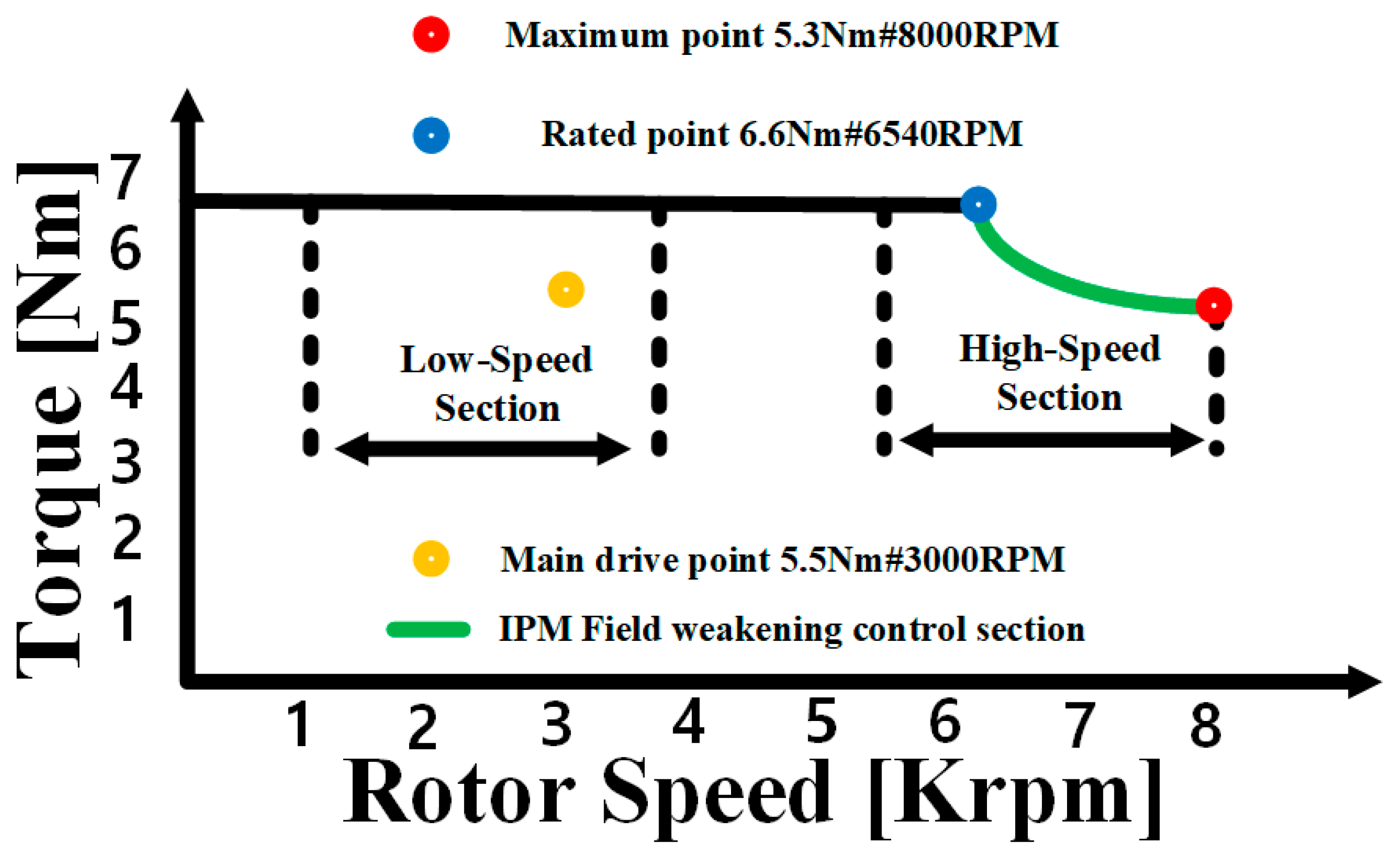
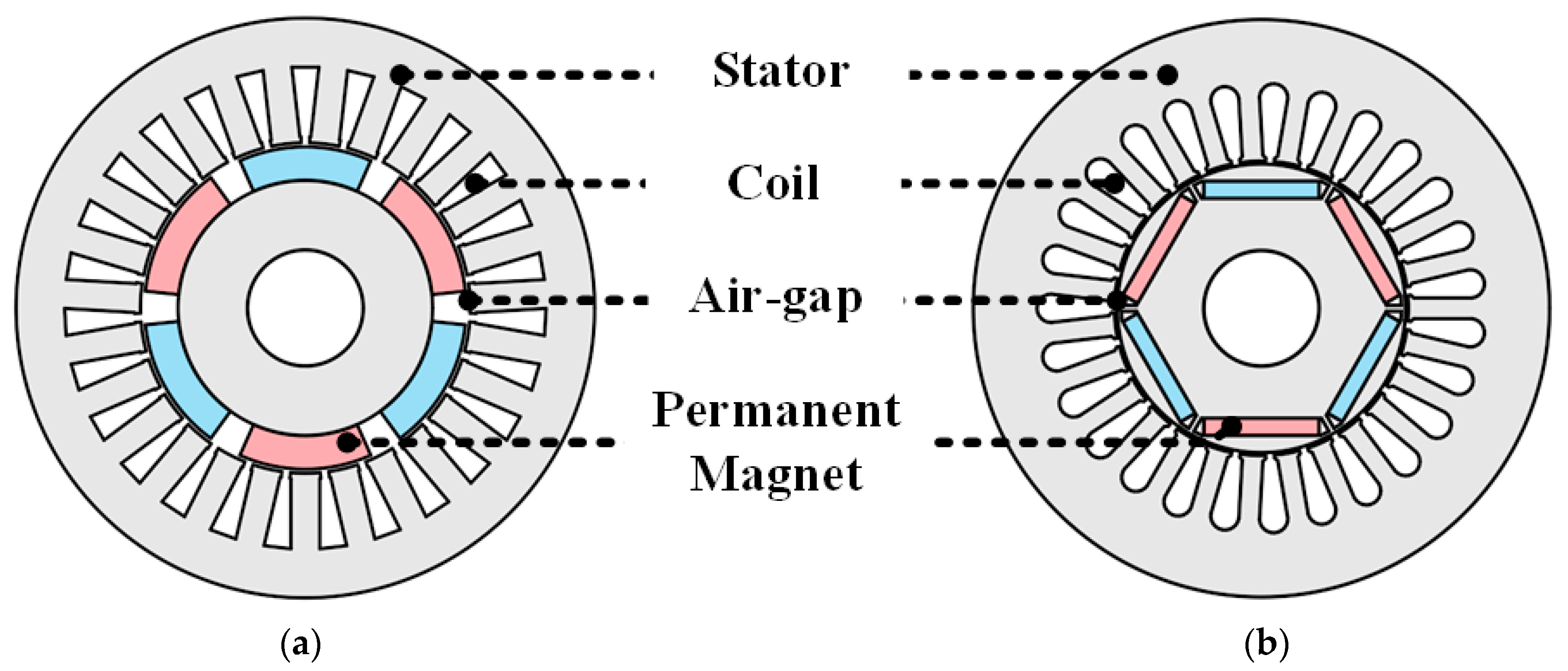
2.1. Analysis Model and Design Requirements

The required performance for each speed section is shown in Figure 1. The PM motor for compressors requires a low speed of 1000–3500 rpm and a high torque of 5–6 Nm, because the amount of exterior air inflow is relatively small when the vehicle is stopped or operated at a low speed [1,2,3,4,5]. However, because the amount of exterior air inflow is relatively large in the high-speed driving section, the cooling capability is not problematic, even if the pressure difference of the compressor is small [1,2,3,4,5]. Therefore, high speeds of 6000–8000 rpm and low torques of 2–4 Nm are required [1,2,3,4,5]. However, suppose that most vehicles drive mainly in the city or run at both high and low speeds. In that case, the main operating point of the electric motor for the compressor is set at 6540 rpm and 6.6 Nm [1,2,3,4,5]. Hence, an electric motor for a compressor must generate a torque of at least 6 Nm, can be operated up to 8000 rpm, and requires maximum efficiency at 6.6 Nm/6540 rpm [1,2,3,4,5].
The analysis models of SPMSM and IPMSM are shown in Figure 2a,b, and the design specifications are listed in Table 1. Here, the rated torque is 6.6 Nm and the rated speed is 6540 rpm, according to the operating conditions of the motor for the aforementioned compressor.

2.2. Design Constraints

The voltage-limiting and current-limiting sources for an SPMSM and an IPMSM are shown in Figure 3. Here, the maximum voltage and current that can be applied from the inverter to the motor are expressed using (1) to (3).
i s max = i d 2 + i q 2
V s max S P M S M = ω λ f 2 + ( L s i q ) 2
V s max I P M S M = ω ( L s i d + λ f ) 2 + ( L s i q ) 2
where i d and i q are the d-axis and q-axis currents, respectively; ω is the mechanical angular velocity of the motor; λ f is the interlinkage magnetic flux owing to the permanent magnet; L s , L d , and L q are the synchronous, d-axis, and q-axis inductances, respectively. When each motor is driven, the maximum torque current control section is reached until the intersection of the current-limiting and voltage-limiting sources is reached, according to the current locus. For the SPMSM, the current limiting source is reached via i d = 0 control; for the IPMSM, the current-limiting source is reached using a negative d-axis current to generate reluctance torque. The speed at this time was 6540 rpm, as shown in Figure 1, and the output torque was 6.6 Nm. When accelerating to the maximum speed after the maximum torque control region, the voltage-limiting source decreases, as shown in (2) and (3). The application of a negative d-axis current results in a field-weakening control region. The output torque at 8000 rpm, which is the maximum speed operating point, was 5.3 Nm.
When designing a PM motor, the voltage limit conditions must be satisfied, and the voltage limit conditions are determined by the DC voltage applied to the inverter and the PWM method [7]. Here, the PWM method is SVPWM, and the voltage limit is determined using (4).
V s max = V d c 3 η i n v e r t e r
where η i n v e r t e r denotes the inverter efficiency and generally ranged from 0.9–0.957. Here, 0.9 was assumed to be the η i n v e r t e r value [7]. According to (4), when the inverter input voltage is 288 [Vdc], the voltage limit is determined to be 150 Vmax. In addition, the current density condition was selected based on water cooling.

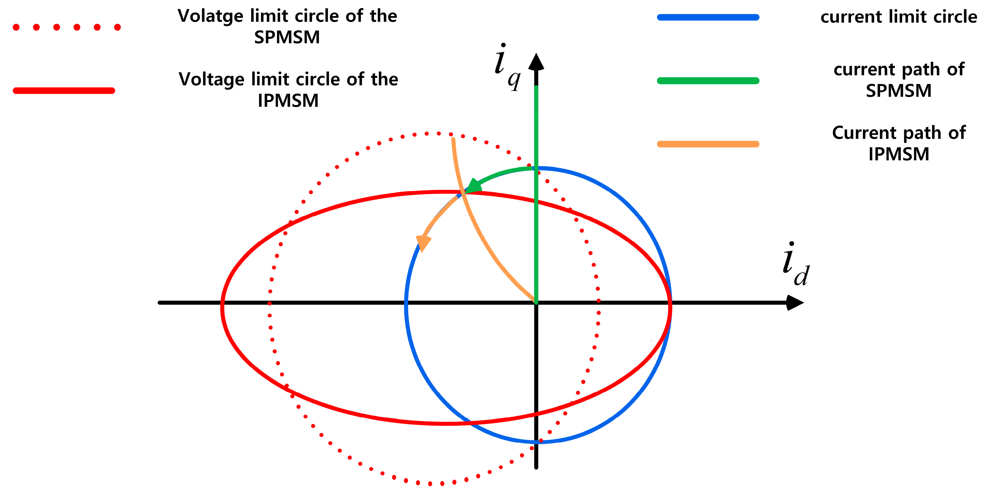
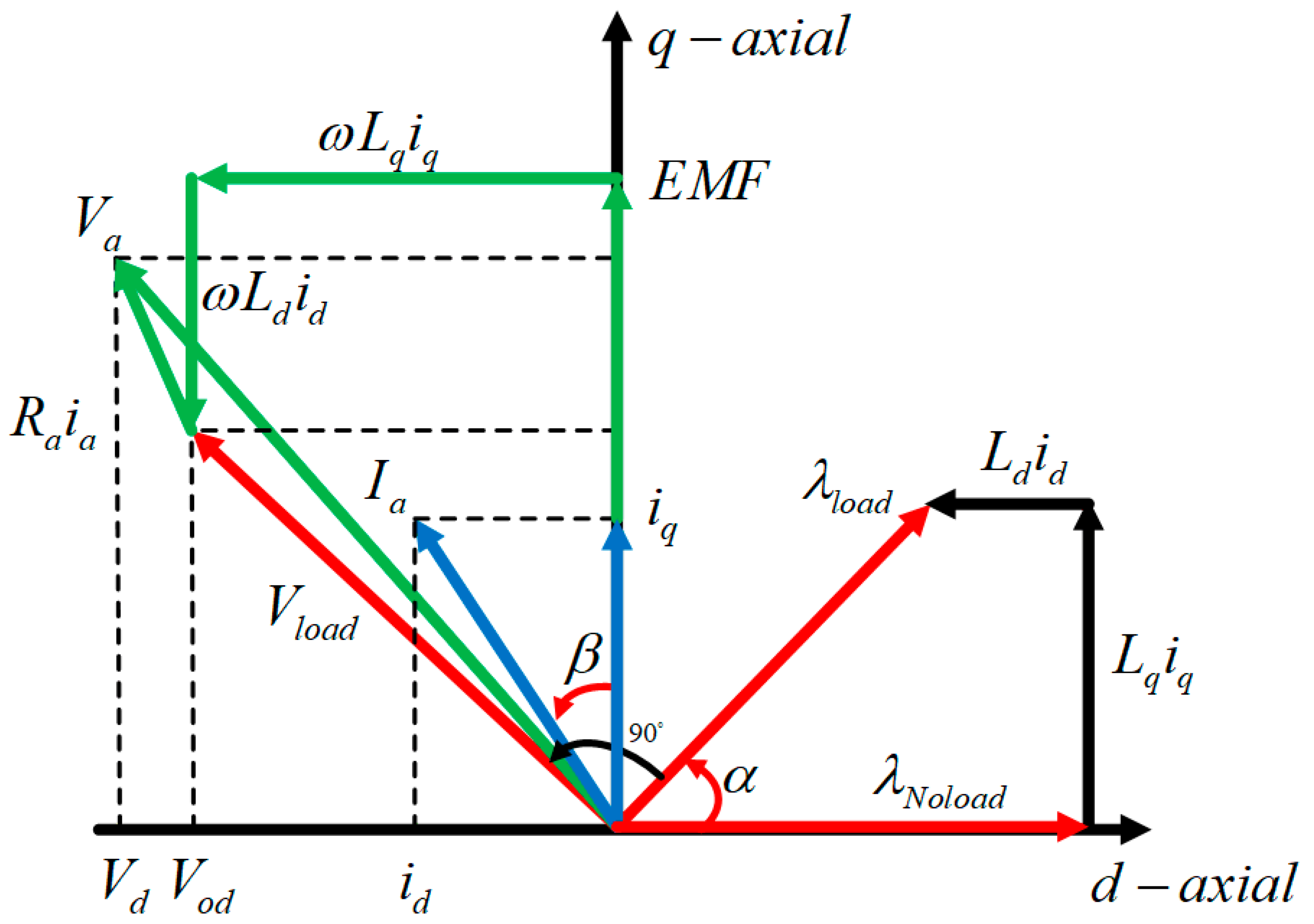
2.3. Characteristics of a PMSM

The characteristics for the performance analysis of PM motors are divided into back EMF, electromagnetic torque, loss, and efficiency. The back EMF should not exceed the voltage limit under no-load and load conditions, and its value should be proportional to the PM material, number of turns, and rotation speed, expressed as follows:
E = N d ϕ l i n k a g e d t
where E, ϕlinkage, and N denote the back EMF, flux linkage, and several turns, respectively [9].
Figure 4 shows a vector diagram showing the relationship between the d- and q-axis inductances and the armature flux. When designing a PM motor, the important parameters of the IPMSM are expressed by the armature flux of the PM and the d- and q-axis inductances. Here, the d-axis, q-axis current and the d-axis, q-axis inductance are determined using Equations (6)–(8).
i d = I a sin β , i q = I a cos α  
L d = λ o cos α λ f i d
L q = λ o sin α i q
where i d , i q , I a , L d , L q , λ o , λ f , α , and β denote the d-axis current, q-axis current, maximum current, d-axis inductance, q-axis inductance, on-load flux linkage, no-load flux linkage, and current phase angle, respectively. The d- and q-axis inductances can be derived through the no- and on-load flux linkage magnitude and phase difference, d-axis current, and q-axis current. The magnitude and phase of the no-load flux linkage were derived through a no-load analysis with no current, and the magnitude and phase of the on-load flux linkage were derived through load analysis with the same applied current.
The electromagnetic torque is divided into cogging and output torques. The cogging torque is generated by the magnetic field harmonics of the PM caused by slotting, according to the stator structure [9]. A constant force is applied to the cogging torque in the direction of rotation or in the direction opposite to rotation. The torque ripple is influenced by the harmonic waves of the cogging torque and back EMF. Hence, it is the primary cause of speed ripple, vibration, and noise. The SPMSM solely adopts magnetic torque, whereas the IPMSM utilizes magnetic and reluctance torques [9]. The output torque in the PMSM can be expressed as follows:
T t o t a l = P 2 3 2 [ λ f i q + ( L d L q ) i d i q ]
where T t o t a l , P , λ f , i d , i q , L d , and L q denote the total torque, number of poles, field-magnet flux linkages, d- and q-axis currents, and d- and q-axis inductances, respectively.
Loss analysis must be performed to evaluate the performance of the motor. Motor losses are divided into copper, core, and eddy-current losses [9]. Copper loss is triggered by winding resistance, whereas iron loss is divided into hysteresis loss, triggered by changes in the iron-core magnetism, and eddy current loss, owing to the iron core conductivity [6]. The hysteresis loss is determined by the number of cycles a magnetic material makes in the hysteresis loop per unit of time [9]. Eddy current loss is triggered by EMF changes owing to the conductivity of the medium as the frequency increases. Here, the modified Steinmetz equation, considering the abnormal eddy current loss, can be expressed as follows:
P c o r e = P h + P e + P a = k h f B n + k e f 2 B 2 + k a f 1.5 B 1.5
where Pcore, Ph, Pe, and Pa represent the core, hysteresis, eddy current, and abnormal eddy current losses, respectively [9]. In addition, k h , k e , and k a denote hysteresis, eddy current loss, and abnormal eddy current loss constants, respectively. Each constant can be calculated from the loss of data versus the frequency.
PM losses are caused by time and space harmonics, slotting, and nonlinear phase-current waveforms [8]. Although its value is smaller than that of copper or core loss, PM loss should be analyzed because it becomes a heat source, which may severely influence the demagnetization of PMs [8]. The PM eddy current loss is expressed as follows:
P p m = ω r 2 π σ J e 2 d V
where Ppm, ωr, σ, and Je denote the PM loss, rotational speed, the conductivity of the PM, and the eddy current in the PM, respectively [9]. Accordingly, the electromagnetic efficiency is expressed as follows:
η = P o u t P o u t + P c o r e + P c o p p e r + P p m
where η and Pout represent the efficiency and output power, respectively [9].

3. Results and Discussion

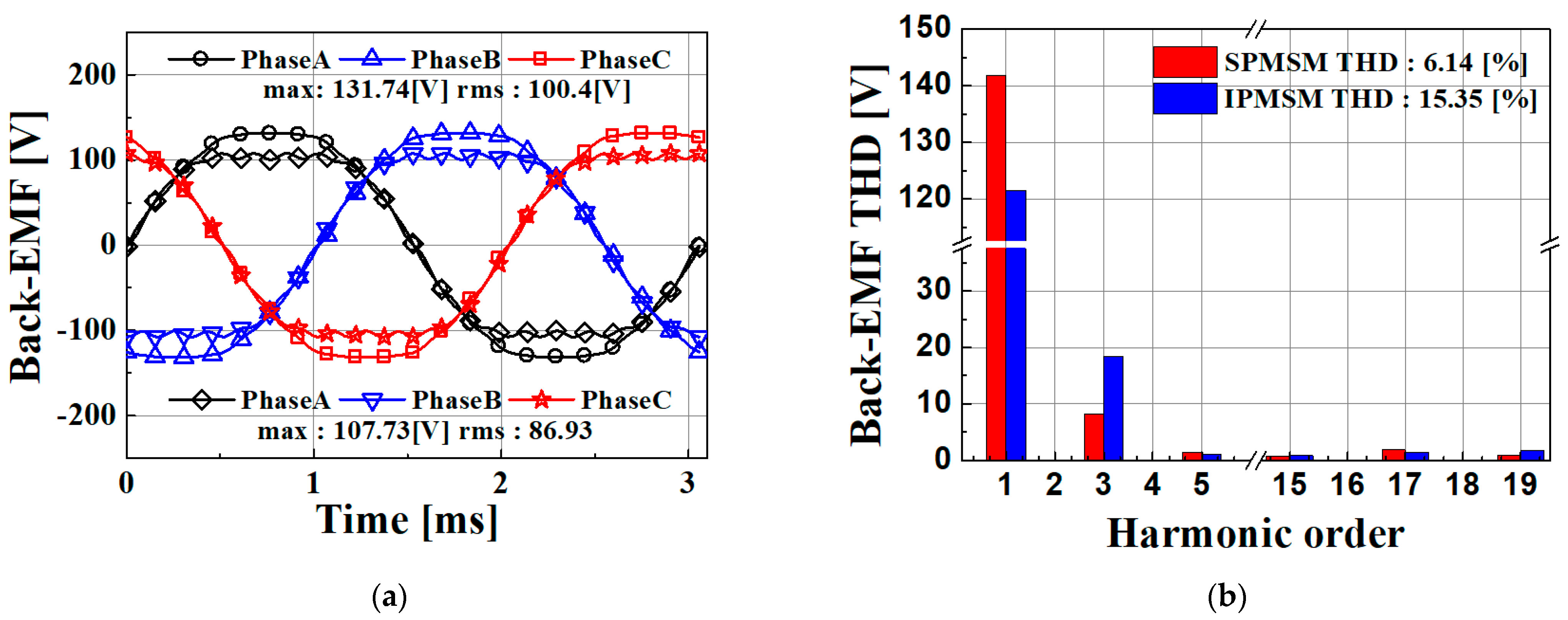
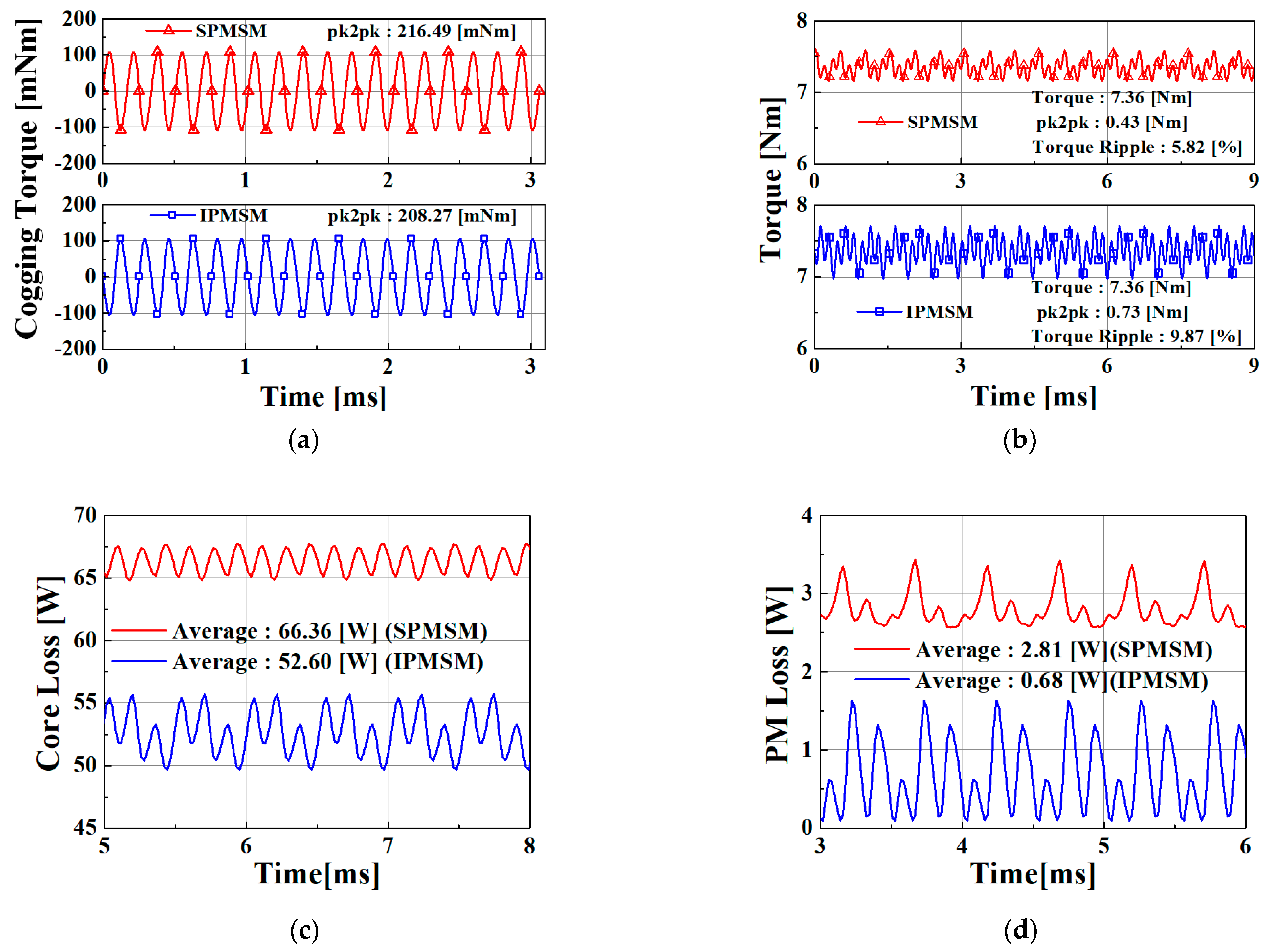
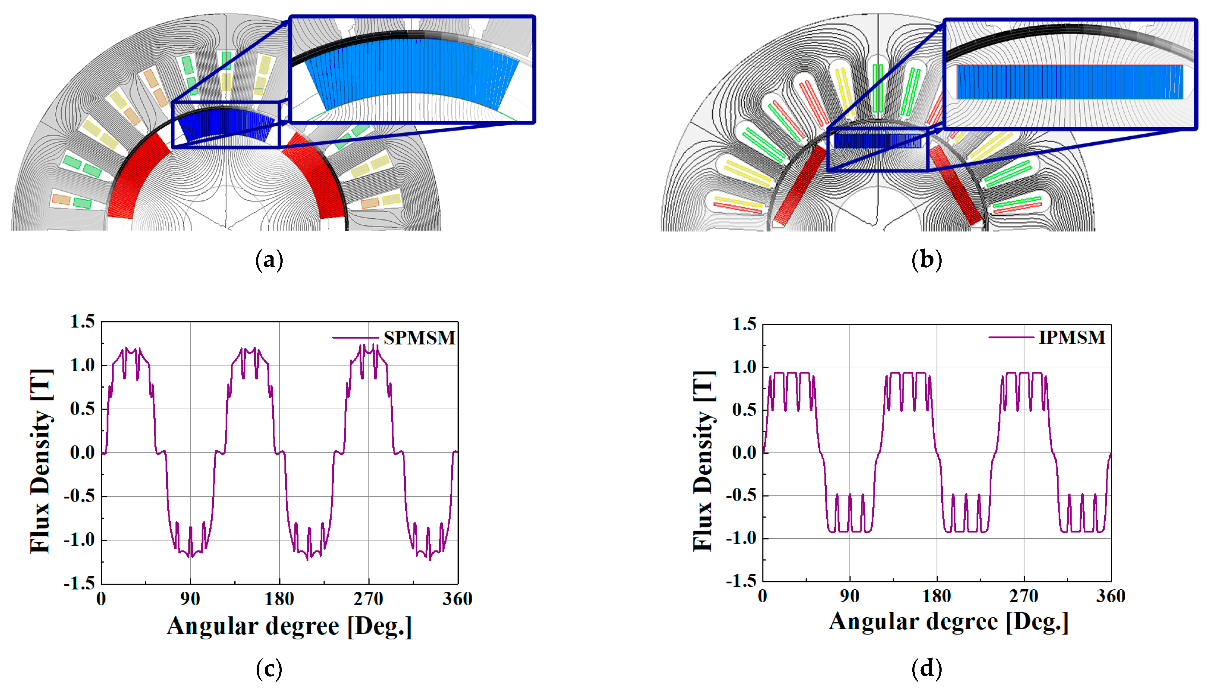
3.1. Comparison of the Electromagnetic Characteristics According to the Rotor Type

Table 2 lists the specifications of the analysis model, and Table 3 lists the analysis results. Here, the outer diameter of the stator, stack length, PM material, and core material of the SPMSM and IPMSM were the same. The back EMF analysis results for each rotor type are shown in Figure 5a. The back EMF was obtained by performing analysis at 6540 rpm under no load, and the SPMSM and IPMSM were selected with seven and eight turns, respectively, to avoid exceeding the previously obtained voltage limit. The back EMF of the IPMSM is distant from the voltage limit because a back EMF exceeds the split voltage limit at turn 9. The back EMF of the IPMSM is small; however, the rated torque can be reached using the reluctance torque.
The results of the FFT analysis of the back EMF are shown in Figure 5b. The THD values of the back EMF of the SPMSM and IPMSM were 6.14% and 15.35%, respectively. The THD of the IPMSM is considerably larger than that of the SPMSM; however, the third-order harmonic does not participate significantly in the state of 3-phase equilibrium, and the fifth-order harmonic that influences the cogging torque is slightly larger than that of the IPMSM. As shown in Figure 6a, the cogging torque of the SPMSM is large. However, this is only a minor difference. The high back EMF THD of the IPMSM can be explained by the magnetic flux density analysis results in Figure 7.
The flux lines of the SPSMSM and IPMSM are shown in Figure 7a,b, respectively. A parallel magnetic flux can be observed by the SPMSM, whereas a radial magnetic flux can be observed by the IPMSM. This is because of differences in the rotor type.
The magnetic flux densities of the SPSMM and IPMSM are shown in Figure 7c and d, respectively. The SPMSM can validate that the magnet is placed on the rotor surface, the magnetic flux emitted from the magnet is not influenced by the rotor core, and the magnetic flux density waveform is a sine wave. Because it is inserted inside the rotor core, it influences the magnetic flux emitted from the permanent magnet, and the waveform of the magnetic flux density is a square wave. The THD of the IPMSM is higher than that of the SPSMM because the magnetic flux density in the form of a square wave influences the harmonics of the back EMF.
The cogging and output torques are shown in Figure 6a and b, respectively. The cogging torque was similar for both models. The torque ripples of the SPMSM and IPMSM were 5.82% and 9.82%, respectively. This result was obtained because the 3rd harmonic of the back EMF of the IPMSM is large in the result shown in Figure 5b.
IPMSM has a higher torque ripple; however, its torque density was approximately twice that of SPMSM, as shown in Table 3. This is because the IPMSM characteristics allow the simultaneous use of magnetic and reluctance torques to increase the overall torque.
The analysis results of the core and PM losses are shown in Figure 6c and d, respectively. The core losses of SPMSM and IPMSM were 66.36 W and 52.6 W, respectively, whereas the PM losses were 2.8 W and 0.7 W, respectively. Here, PM loss is the eddy current loss caused by the permanent magnet.
The SPMSM had a higher magnetic flux saturation than the IPMSM. For the PM loss, the magnetic field owing to the armature reaction caused by the input current interacts more directly than in the IPMSM. In addition, the SPMSM has a longer effective air gap than the IPMSM, owing to the sleeves applied to prevent the scattering of permanent magnets. Accordingly, a large amount of PM loss occurs because the utilization of the permanent magnet is increased to produce the same output.
The copper loss of the IPMSM exceeds that of the SPMSM by 97 W, as listed in Table 3. The copper loss was proportional to the current; accordingly, the copper loss of the IPMSM was more than that of the SPMSM at an applied current of 2.4 A. The efficiency of this approach can be deduced using (11). Consequently, the SPMSM and IPMSM exhibited efficiencies of 93.8% and 92.3%, respectively. Hence, the SPMSM was more efficient than the IPMSM for the same specification.

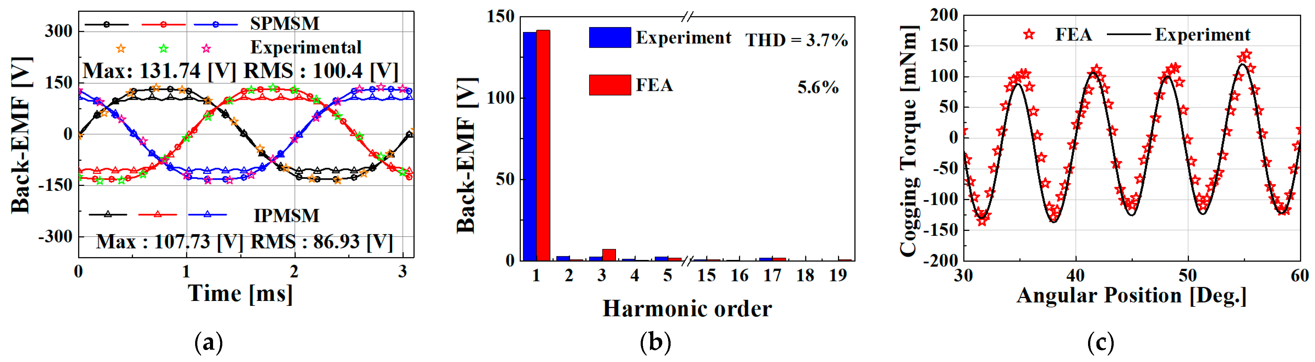
3.2. Experimental Result and Discussion

A back-to-back experimental setup to measure motor performance is shown in Figure 8. A commercial inverter was connected to the winding of the IPMSM to operate as an electric motor, and an experiment was conducted on the SPMSM at no load to measure the back EMF, back EMF THD, and cogging torque.
The experimental data of the SPMSM back EMF are shown in Figure 9a. The experiments were performed at the rated speed and the experimental results were compared with the FEA results. This result agreed with the experimental data.
The FFT experimental results of the no-load back EMF are shown in Figure 9b. From the FFT results, the difference between the three harmonics is large, and in a 3-phase motor, the torque ripple is independent of the 3rd harmonic; therefore, its effect on the drive characteristics of the motor is insignificant.
The experimental result of the FFT differed from that of the FEA. This might result from the manufacturing tolerances and uneven seating of the permanent magnets.
The experimental results of the cogging torque are shown in Figure 9c. We measured the cogging torque at a rotational speed of 3 rpm. The harmonic components of the cogging torque were inversely related to the least common multiple of the number of poles and slots. Here, the harmonic is based on the frequency of the fundamental wave, which is the number of rotations per second; the least common multiple was 54, because both motors had six poles and 27 slots. Therefore, the frequency of the cogging torque had 54 harmonics with respect to the revolutions per second; because the lowest common multiple is relatively large, the cogging torque is expected to be small. The experimental results were in good agreement with the FEA results.

4. Conclusions

This study analyzed and compared the characteristics of SMPSMs and IPMSMs for EV air conditioner system compressors.
The motor requirement rating and limitation specifications were determined by considering the operating conditions of the compressor and the vehicle requirements. The surface-attached and embedded permanent magnet motors were designed using the design equation and finite element method according to the determined requirements/limiting conditions. We derived and compared the electromagnetic properties, such as copper loss, iron hand, cogging torque, back EMF THD, efficiency, and torque ripple, of the two rotor types. In the case of the IPMSM, the current phase angle was controlled by obtaining the inductance, and the torque was derived using the inductance.
In terms of efficiency, the SPMSM exceeded the IPMSM by 1.5%; however, because the SPMSM wrapped the rotor surface with a sleeve to prevent the scattering of permanent magnets, the length of the voids increased and the number of magnets increased. Therefore, the SPMSM used more rare earth magnets, with 270 g of SPMSM and 130 g of IPMSM.
Therefore, considering manufacturing performance and cost, the IPMSM is considered optimal for EV compressors.

Author Contributions

J.-Y.C.: conceptualization, review, and editing; W.-S.J.: analysis, original draft preparation; H.-K.L.: experiment and motor control algorithm; Y.-K.L.: experiment, motor control algorithm, and co-simulation; S.-M.K.: co-simulation; J.-I.L.: co-simulation. All authors have read and agreed to the published version of the manuscript.

Funding

This work was supported by the BK21 FOUR Program of Chungnam National University Research Grant 2022. And this work was supported by the Korea Institute of Energy Technology Evaluation and Planning (KETEP) and the Ministry of Trade, Industry & Energy (MOTIE) of the Republic of Korea. (No. 20183010025420).

Data Availability Statement

The data presented in this study are available upon request from the corresponding author.

Conflicts of Interest

The authors declare no conflict of interest.

References

  1. Choi, J.-Y.; Park, H.-I.; Jang, S.-M.; Lee, S.-H. Design and Analysis of Surface-Mounted PM Motor of Compressor for Electric Vehicles Applications according to Slot/Pole Combinations. Trans. Korean Inst. Electr. Eng. 2011, 60, 1846–1857. [Google Scholar] [CrossRef] [Green Version]
  2. Duane, H. Brushless Permanent Motor Design. Ph.D. Thesis, Maine University, Orono, ME, USA, 2010. [Google Scholar]
  3. Bae, J.N. Permanent Magnet Synchronous Machine Design through and Automatic Selection of the Specific Loadings. Ph.D. Thesis, Hanyang University, Seoul, Republic of Korea, 2010. [Google Scholar]
  4. Cho, S.-K.; Jung, K.-H.; Choi, J.-Y. Design Optimization of Interior Permanent Magnet Synchronous Motor for Electric Compressors of Air-Conditioning Systems Mounted on EVs and HEVs. IEEE Trans. Magn. 2018, 54, 1–5. [Google Scholar] [CrossRef]
  5. Shin, K.-H.; Choi, J.-Y.; Cho, H.-W. Characteristic Analysis of Interior Permanent-Magnet Synchronous Machine with Fractional-Slot Concentrated Winding Considering Nonlinear Magnetic Saturation. IEEE Trans. Appl. Supercond. 2016, 26, 1–4. [Google Scholar] [CrossRef]
  6. Tomigashi, Y.; Ueta, T.; Yokotani, K.; Ikegami, K. Reducing Cogging Torque of Interior Permanent Magnet Synchronous Motor for Electric Bicycles. In Proceedings of the IEEE European Conference on Power Electronics and Applications, Dresden, Germany, 11–14 September 2005. [Google Scholar]
  7. Yang, Z.; Shang, F.; Brown, I.P.; Krishnamurthy, M. Comparative Study of Interior Permanent Magnet, Induction, and Switched Reluctance Motor Drives for EV and HEV Applications. IEEE Trans. Transp. Electrif. 2015, 1, 245–254. [Google Scholar] [CrossRef]
  8. Studer, C.; Keyhani, A.; Sebastian, T.; Murthy, S.K. Study of cogging torque in permanent magnet machines. In Proceedings of the Industry Applications Conference, 1997. Thirty-Second IAS Annual Meeting, IAS’97, Conference Record of the 1997 IEEE, New Orleans, LA, USA, 5–9 October 1997; Volume 1, pp. 42–49. [Google Scholar]
  9. Kim, B.-T.; Kwon, B.-I.; Park, S.-C.; Kwon, B.-I. Reduction of electromagnetic force harmonics in asynchronous traction motor by adapting the rotor slot number. IEEE Trans. Magn. 1999, 35, 3742–3744. [Google Scholar] [CrossRef]
  10. Bianchi, N.; Bolognani, S. Design techniques for reducing the cogging torque in surface-mounted PM motors. IEEE Trans. Ind. Appl. 2002, 38, 1259–1265. [Google Scholar] [CrossRef]
  11. Dai, M.; Keyhani, A.; Sebastian, T. Torque Ripple Analysis of a PM Brushless DC Motor Using Finite Element Method. IEEE Trans. Energy Convers. 2004, 19, 40–45. [Google Scholar] [CrossRef]
  12. Fang, L.; Jung, J.-W.; Hong, J.-P.; Lee, J.-H. Study on High-Efficiency Performance in Interior Permanent-Magnet Synchronous Motor with Double-Layer PM Design. IEEE Trans. Magn. 2008, 44, 4393–4396. [Google Scholar] [CrossRef]
  13. Ge, H.; Miao, Y.; Bilgin, B.; Nahid-Mobarakeh, B.; Emadi, A. Speed Range Extended Maximum Torque Per Ampere Control for PM Drives Considering Inverter and Motor Nonlinearities. IEEE Trans. Power Electron. 2016, 32, 7151–7159. [Google Scholar] [CrossRef]
  14. Mohamed, Y.A.I.; Lee, T.K. Adaptive self-tuning MTPA vector controller for IPMSM drive system. IEEE Trans. Energy Convers. 2006, 21, 636–644. [Google Scholar] [CrossRef]
Figure 1. Required torque–speed curve of the motor for the compressor applications.
Energies 16 01306 g001
Figure 2. Analysis model and experimental setup: (a) SPMSM, (b) IPMSM.
Energies 16 01306 g002
Figure 3. Voltage and current limit circle of the SPMSM and IPMSM.
Energies 16 01306 g003
Figure 4. Vector diagram of IPMSM.
Energies 16 01306 g004
Figure 5. Characteristic analysis results: (a) back EMF, (b) back EMF FFT.
Energies 16 01306 g005
Figure 6. Results of characteristic analysis: (a) cogging torque; (b) torque ripple. loss analysis results: (c) coreloss; (d) PM loss.
Energies 16 01306 g006
Figure 7. Flux density analysis results: (a) flux lines of SPMSM; (b) flux lines of IPMSM; (c) flux density of SPMSM (d) flux density of IPMSM.
Energies 16 01306 g007
Figure 8. Experimental setup of the SPMSM and IPMSM.
Energies 16 01306 g008
Figure 9. Experimental result: (a) back EMF; (b) back EMF FFT; (c) cogging torque.
Energies 16 01306 g009
Table 1. Design specifications.
ParameterValueParameterValue
Rated torque6.6 NmInput voltage288
Rated power4.5 KWPWMSVPWM
Rated speed6540 rpmVoltage limit150 (Vmax)
Maximum speed8000 rpmCurrent density20 (Arms/m2)
Stack length100 mmEfficiency92%
Air gap0.5 mm
Table 2. Analysis model specifications.
ParametersSPMSMIPMSM
Inner diameter of the rotor (mm)55.650
Inner diameter of the stator (mm)5751
Outer diameter of the stator (mm)100100
Stack length (mm)5050
PM thickness (mm)5.83
Amount of magnet (g)270130
PM materialNdFe42NdFe42
Core material35PN25035PN250
Turn78
Table 3. Analysis results.
ParametersSPMSMIPMSM
Output torque (Nm)7.357.36
Input current (A)16.8318.53
Power (W)50395039
Core loss (W)66.3652.6
PM loss (W)2.810.68
Copper loss (W)265.7368
Current density (A/mm2)16.7418.43
Efficiency (%)93.892.3
Torque density (Nm/Kg)27.2256.61
Disclaimer/Publisher’s Note: The statements, opinions and data contained in all publications are solely those of the individual author(s) and contributor(s) and not of MDPI and/or the editor(s). MDPI and/or the editor(s) disclaim responsibility for any injury to people or property resulting from any ideas, methods, instructions or products referred to in the content.

