

Parameter Identification of Asynchronous Load Nodes


1
Department of Transport Electric Power, Irkutsk State Transport University, 664074 Irkutsk, Russia
2
Department of Power Supply and Electrical Engineering, Irkutsk National Research Technical University, 664074 Irkutsk, Russia
3
Department of Hydropower and Renewable Energy, National Research University “Moscow Power Engineering Institute”, 111250 Moscow, Russia
4
Department of Research on the Relationship between Energy and the Economy, Energy Research Institute of the Russian Academy of Sciences, 117186 Moscow, Russia
5
Department of Power Engineering, Kazan State Power Engineering University, 420066 Kazan, Russia
*
Author to whom correspondence should be addressed.
Energies 2023, 16(4), 1893; https://0-doi-org.brum.beds.ac.uk/10.3390/en16041893
Submission received: 9 January 2023
/
Revised: 9 February 2023
/
Accepted: 11 February 2023
/
Published: 14 February 2023
(This article belongs to the Special Issue Condition Monitoring and Failure Prevention of Electric Machines)
Abstract
:Asynchronous loads (AL), because of their low negative-sequence resistance, produce the effect of reduced unbalance at their connection points. Therefore, proper modeling of unbalanced load flows in power supply systems requires properly accounting for AL. Adequate models of the induction motor can be realized in the phase frame of reference. The effective use of such models is possible only if accurate data on the parameters of induction motor equivalent circuits for positive and negative sequences are available. Our analysis shows that the techniques used to determine these parameters on the basis of reference data can yield markedly disparate results. It is possible to overcome this difficulty by applying parameter identification methods that use the phase frame of reference. The paper proposes a technique for parameter identification of models of individual induction motors and asynchronous load nodes. The results of computer-aided simulation allow us to conclude that by using parameter identification, we can obtain an equivalent model of an asynchronous load node, and such a model provides high accuracy for both balanced and unbalanced load flow analysis. By varying load flow parameters, we demonstrate that the model proves valid over a wide range of their values. We have proposed a technique for the identification of asynchronous load nodes with such asynchronous loads, including electrical drives equipped with static frequency converters. With the aid of the AL identification models proposed in this paper, it is possible to solve the following practical tasks of management of electric power systems: increasing the accuracy of modeling their operating conditions; making informed decisions when taking measures to reduce unbalance in power grids while accounting for the balancing adjustment effect of AL.
1. Introduction
The electric power system (EPS) is a set of complex devices that generate, transmit, distribute, and consume electric power. Improving the reliability of operation and efficiency of power system use is impossible without solving a set of problems relating to load dispatching in ordinary and emergency states. Due to the introduction of transient monitoring tools, it became possible to determine the parameters of power system elements in real-time.
Solving the problems of load dispatching in EPSs is based on the use of mathematical models. They are used for steady-state load flow analysis, optimization, state estimation, transient analysis, etc. The basis of the mathematical model of an EPS is an equivalent circuit, which is formed from the circuits of individual components, namely: power transmission lines, power transformers, generating equipment, load nodes, etc. The parameters of the equivalent circuit of each component are usually determined by reference data or nameplate data and are considered immutable, although they depend on wear and tear of components, weather conditions, and other factors. The errors in determining these parameters on the basis of reference data are quite significant. For example, the error of the active resistance of a line can be in the range of +16–−20%, and the representation of corona discharge losses by a constant value of active conductivity can lead to an error of 1.5–3 times the actual value when determining the losses. The most significant errors can occur in the process of building the models of load nodes. This is due to the considerable uncertainty in the mix of consumers served and their operating conditions. The problem of adequate modeling of load nodes can be solved on the basis of identification methods.
Issues of parameter identification of induction machines and nodes with predominantly unbalanced loads have been addressed in a sizeable number of studies. For example, article [1] proposed a technique for identifying the parameters of a three-phase induction motor in the case when the initial values of the estimates change in a wide range. Study [2] presented the results of an experimental study of the efficacy of the technique of adaptive identification of electrical parameters of the induction machine under steady-state conditions on the basis of the power balance. Article [3] dealt with the issues of the identification of load nodes and their stability control. In [4,5,6], the results of the modeling and identification of an induction machine were presented. Article [7] discussed the identification of the parameters of an induction motor in its operational mode. Study [8] described an algorithm proposed by its authors for the identification of induction machine parameters by a recursive least-squares method. Article [9] studied mathematical methods of identification of lumped parameters of electrical machines. It discussed the basic principles and mathematical foundations of lumped parameter identification methods for various types of electrical machines, including induction machines. Article [10] proposed an approach to parameter identification of induction machines. The excitation input signal was determined by optimization methods. Instrumental variable estimation was introduced to improve the quality of identification by least-squares estimation. A method for magnetizing curve identification of induction machines was described in [11]. The study proposed an experimental method for determining the magnetization curve specifically designed for vector-controlled drives. The method employed an indirect vector controller and a PWM inverter, which were used during normal operation of the drive. The method was verified by extensive experimentation. A novel parameter identification method for the induction motor (IM) was proposed in [12]. The study pointed out that the effect of vector control depends largely on the accuracy of setting its parameters, which change with temperature variation. Based on the relationship between motor winding resistance and temperature, the authors presented a method for calculating dynamic resistance by on-line detection of the winding temperature. The experiment results attested to the high identification accuracy of the approach. Article [13] considers real-time parameter identification algorithms for effective control of electrical machines. Study [14] proposed a technique of flux estimation of induction machines with the linear parameter-varying system identification method. The identification algorithm was tested on data obtained from a nonlinear simulation model with continuous time. Paper [15] described a method for parameter identification of nine-phase induction machines with concentrated windings. Studies [16,17] considered a method of induction machine parameter identification suitable for self-commissioning. An algorithm for parameter identification of electrical machines using numerical simulations was proposed in articles [18,19]. The problem of reducing the electrical energy consumption of fans through parameter identification of the drive was solved in [20]. A method for identification of induction machine parameters, including core loss resistance, using a recursive least mean square algorithm was proposed in [21].
An analysis of the research contributions reviewed above allows us to conclude that the relevance of problems with parameter identification of IMs and asynchronous load nodes has been well established. However, most of the reviewed works dealt with the determination of parameters of individual IMs, whereas load nodes were considered only in [3]. The study relied on a single-line representation of the power system, which significantly hindered the modeling of unbalanced load flows. Adequate models of IMs and asynchronous load nodes in the phase frame of reference, which is the most natural form of representation of multiphase circuits, were proposed in [22,23]. However, effective use of such models is possible only if accurate data on the parameters of IM equivalent circuits for positive and negative sequences are available. The parameter identification techniques discussed below can be used to solve this problem.
2. Modeling of Unbalanced Loads in the Phase Frame of Reference
On the basis of phase coordinates, adequate models [22] of asymmetric modes of complex electric power systems at the fundamental frequency and frequencies of higher harmonics can be implemented. So, for example, an experimental verification of the EPS modeling technique in phase coordinates, performed on the basis of comparison with synchronized measurement data for a model containing 619 nodes and 2996 branches, showed that the differences between the calculated and measured values of the asymmetry coefficients do not exceed 0.6%, and for the phase values stresses 2.3%.
Compared to the static elements of an EPS, such as power lines and transformers, an asynchronous load, including a large number of motors, is a more complex object.
The asymmetry of the resistance matrix corresponding to the motor poses challenges to simulation based on the lattice circuit with RLC elements. The difficulties are due to the presence of two magnetic fields rotating clockwise and counterclockwise. When the supply voltages are unbalanced, the induction motor has sine wave processes running at three frequencies: 50 Hz, the frequency of the slip s, and about 100 Hz.
The behavior of induction motors under balanced three-phase voltage, when the motor can be represented by a single-line equivalent circuit, has been thoroughly researched. Induction motors can have different parameters of equivalent circuits during starting up and operation with low slip values. Furthermore, there are several variants of equivalent circuits. From the standpoint of load flow analysis in the phase frame of reference, when it is necessary to consider motor parameters at low slip values as well as at slip values close to 2 (electromagnetic brake mode), it is advisable to make the following assumptions.
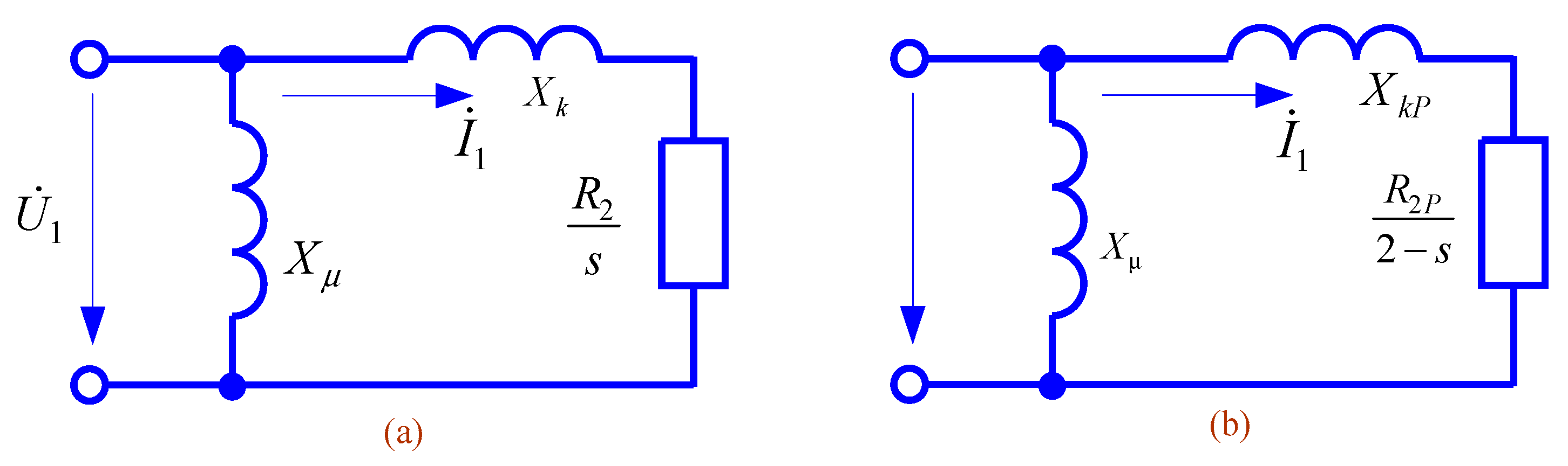
First, it is convenient to use the equivalent circuit of an induction motor with the external magnetizing circuit placed on the primary terminals, according to Figure 1a. It is assumed that at start-up and the slip value of 2 − s (for negative sequence voltage), the equivalent circuit will have different parameters of the rotor circuit, Figure 1b. Figure 1 shows the magnetization branch components Rμ, Xμ, stator resistances R1, X1, and equivalent rotor resistances referred to the stator , X2, as well as the corresponding starting parameters , .
Second, it was assumed that in the start-up and electromagnetic brake modes (for the negative voltage sequence), the square of the reactive resistance is much greater than the square of the active resistance.
Third, with respect to the magnetization branch, a dual approach was adopted. When the no-load parameters are known (cosφx and active power Px), its parameters are determined on the basis of the relations presented below, and when the parameters are unknown, the magnetization branch is ignored.
Fourth, the parameters of the circuit components in Figure 1 are determined from the rated values of efficiency η, power factor cos φH, current IGH, and the current flowing through the part of the circuit that determines the load flow.
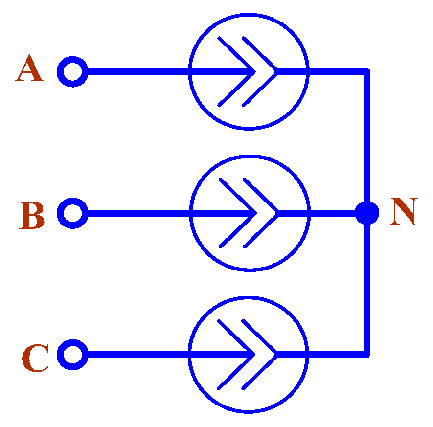
Fifth, the values of the positive and negative sequence voltages and the given mechanical power of the motor are used to determine the positive and negative sequence currents. In this case, the motor is modeled by current sources connected in a star (Figure 2). The values of the source currents are adjusted at each step of the iterative process. The motor neutral is considered to be insulated, and no zero-sequence currents occur in its circuits.
According to Figure 1a, the parameters of the circuit at rated power settings for the positive sequence are determined from the values of efficiency η, rated current IGH, and power factor cos φH.
If the active power Px and cos φx of the no-load operation of the motor are known, the parameters of the magnetizing branch and the current flowing through it can be determined from them:
The mechanical shaft power of the motor at rated settings is determined by the active power dissipated in the resistance , where is the rated slip. The efficiency factor is made up of the following loss components:
- mechanical losses in the rotor ;
- steel losses in the stator ;
- additional losses in the stator ;
- copper losses due to stator and rotor resistances R1 and R2.
The efficiency at rated power settings is defined as the ratio of shaft power to gross power:
The magnetizing branch current when the vectors are counted from the voltage is
At rated load, the motor current is
where is the active power consumed at rated power settings.
The rated current and power factor are determined by the expressions:
However, if the no-load operation parameters of the motor are unknown, it is possible to assume, by way of approximation, that neglecting the magnetizing current and considering that .
The system of Equations (2), (7) and (8) is solved by simple substitution. From Equation (8) we determine
and it follows from Equation (7) that , so that .
From relations (2) and (9) we can determine components and :
When determining R0 from relation (3), it can be assumed that the added losses are 0.5% of the input power and that the mechanical losses are 1.0% of the rated power.
Denoting and assuming that , we obtain
where is the locked-rotor current ratio. From the equation of the electromagnetic locked-rotor torque when the magnetization branch is ignored, we get the relation
where p is the number of motor pole pairs.
The locked-rotor torque was determined from the locked-rotor torque ratio and the rated torque , from which it follows that
The multiplier allows one to convert the shaft power to the electromagnetic power of the motor with a small error.
Effective use of the described model is possible only if accurate data on the parameters of IM equivalent circuit for positive and negative sequences are available. This problem can be solved by applying the parameter identification technique [22], described below. Identification results can be used in the unbalanced load flow analysis of complex power supply systems. In this case, the asynchronous load node can be represented by an equivalent IM according to the technique detailed in [24].
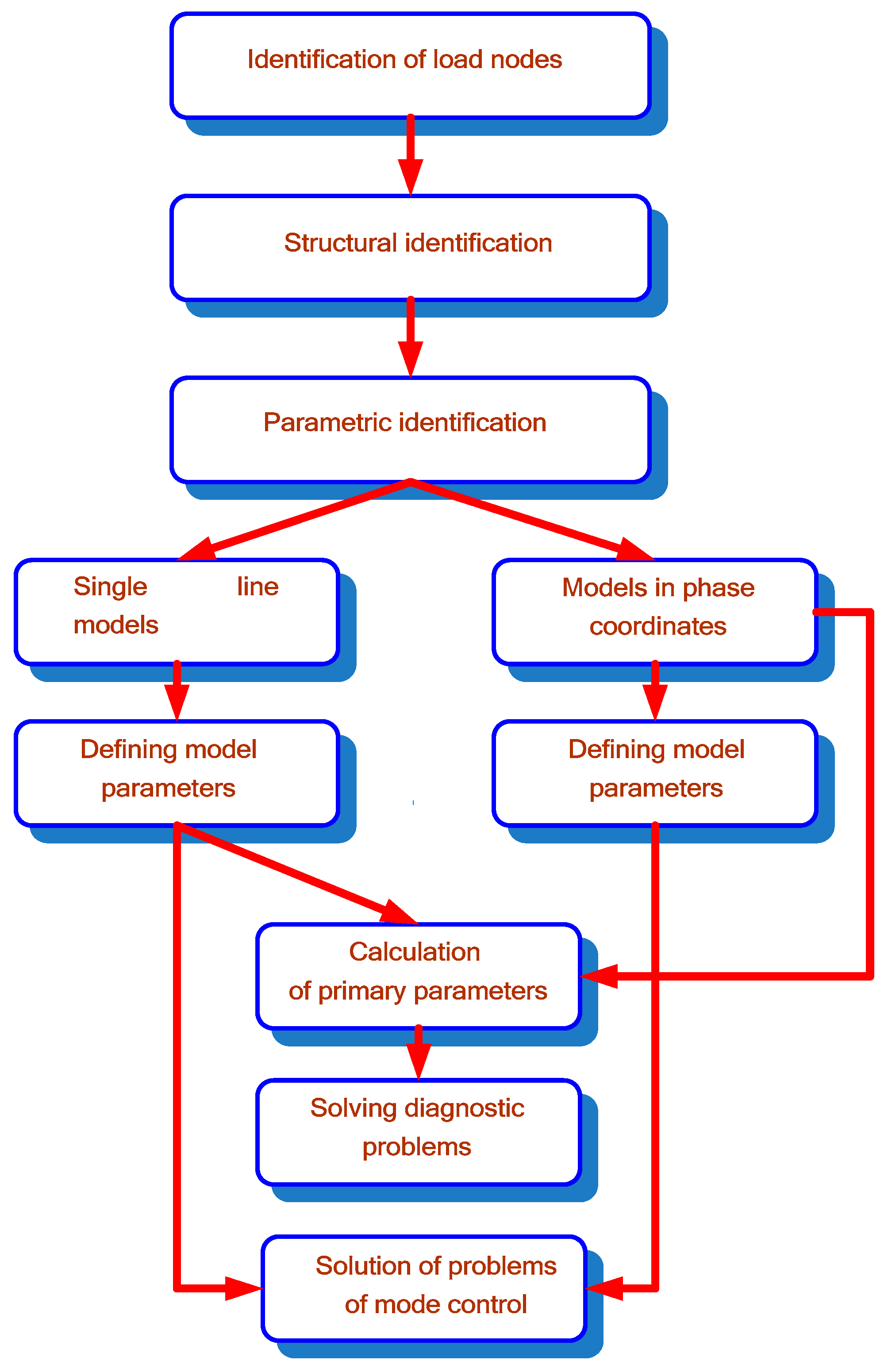
3. Induction Motor Identification Technique
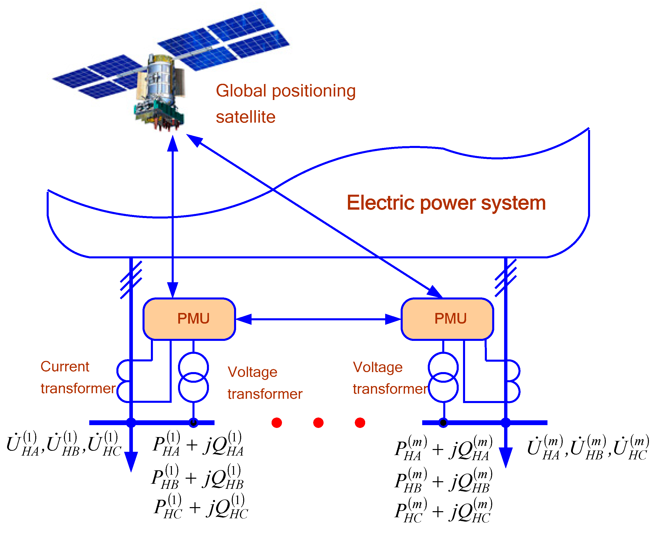
The problem of adequate modeling of load nodes can be solved on the basis of identification methods. In the context of power system control, it is advisable for identification purposes to use information about parameters of operating conditions obtained from information and measurement systems built using PMUs (Figure 3).
The problem of topology and parameter identification of load nodes can be formalized as follows [22,25]. To this end, we can introduce a class of models describing the processes occurring at load nodes. Each of the models is represented as
where —state variables; —input variables; —model parameters subject to identification; —internal relations defining the model structure; —functional relationships acting as mathematical relations operators allowing to find the parameters describing the object state by inputs , , with the required degree of certainty.
Then we can write
This relationship is called the rule governing the functioning of the model. To form the relationship (10), it is necessary to choose from a class of models a model with the rule
The parentheses in the last relation denote that is a partially defined relation; that is, not all characteristics of the original are captured by the model, but only those that are deemed significant in solving the stated problem of modeling power system conditions.
The functional transformation can be chosen subject to the following condition
in some parts of the chosen class of functions.
In addition, the choice of can be made subject to the condition that there be a minimum of some criterion of discrepancy between the model and the original:
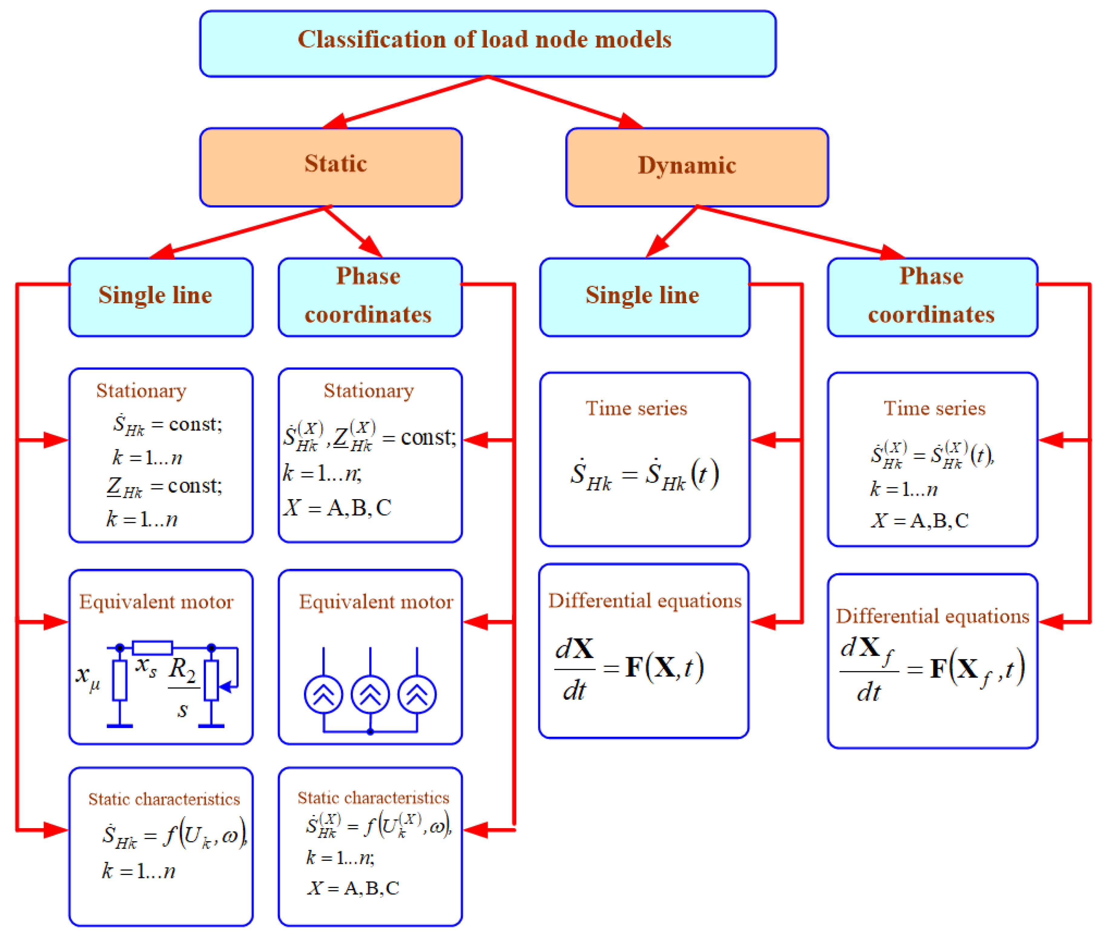
As a rule, the choice of the functional transformation , carried out at the stage of structural identification, is subjective and does not lend itself easily to rigorous formalization. Figure 4 is a diagram showing possible types of load node models.
Parameters can be determined on the basis of measurements of complexes of currents consumed by the motor and voltages at its terminals, as well as its rotation speed. To solve this problem, it is necessary to know the resistance of the magnetizing branch . This parameter can be found on the basis of additional measurements, e.g., under no-load conditions, or determined by the indirect technique described below.
If the value of is known, the parameters of the equivalent circuit of the positive sequence can be found based on measurements of the moduli and phases of the IM currents and voltages, as well as the speed of rotation (slip ) based on the following relation:
where ; ; are complexes of positive sequence voltage and current, determined on the basis of measurements of phase currents and voltages according to the known relations of the method of symmetrical components. Measurements can be made under both balanced and unbalanced load flows.
The main practical focus of the research presented in the article is to create methods for adequately taking into account load nodes when modeling stationary modes of electric power systems. Therefore, for further consideration, the model of the load node in phase coordinates in the form of an equivalent asynchronous electric motor was adopted. To solve the identification problem, it is necessary to measure the parameters of load nodes, which can be determined on the basis of PMU-WAMS devices (Figure 3 and Figure 5).
Based on (11), we can write the following expression:
If the slip is known, the parameter can be determined from the above equation.
The parameters of the equivalent circuit of the negative sequence can be found as per equations similar to those given above:
where — complexes of negative sequence currents and voltages are determined by measurements of phase currents and voltages. To obtain acceptable accuracy, the parameters of start-up conditions should be found in the power flow with a voltage unbalance ( of about 10%).
The resistance can be determined by the data provided in reference books. All that is required is information about the rated voltage and the rated motor power. An acceptable accuracy of calculation of can be obtained on the basis of a nonlinear approximation of the following kind:
Parameters , , and , for IM powers exceeding 5 kW are given in Table 1.
The obtained value should be multiplied by the basic resistance, determined by the rated parameters of the IM.
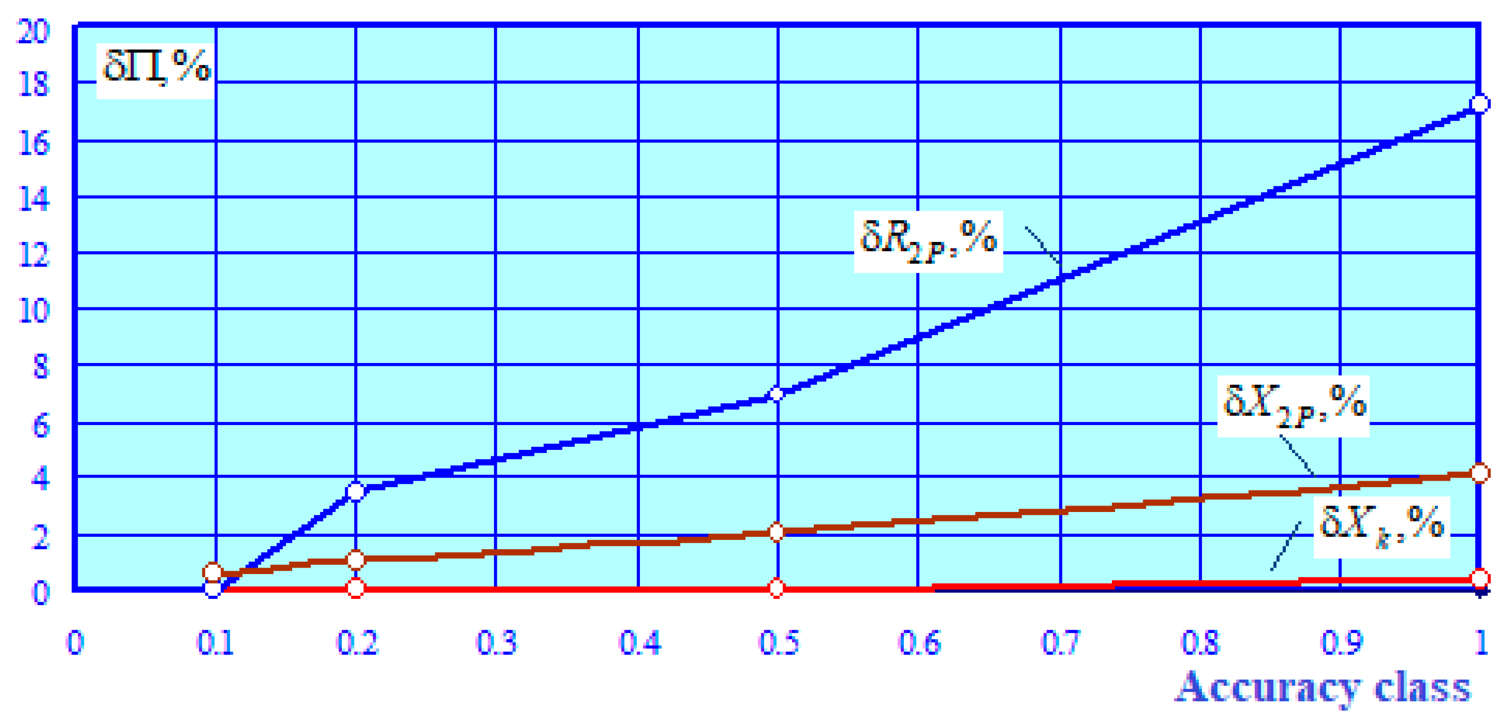
4. Identification Results
Input information in the form of moduli and angles of current and voltage, as well as those of slip, was formed on the basis of computer-aided simulation using the software package Fazonord [22]. For this purpose, an equivalent circuit of an IM with a rated power of 90 kW was created. In the obtained currents and voltages of the calculated load flow, the errors corresponding to the accuracy classes of measuring instruments (0.1, 0.2, 0.5, and 1) were introduced. The resistance was calculated on the basis of expression (12). The results of the identification are shown in Figure 6. The parameter was determined with an error close to zero.
The results obtained show that in order to achieve acceptable identification accuracy, it is necessary to use measuring instruments with an accuracy class that provides a maximum error of no more than 0.2%.
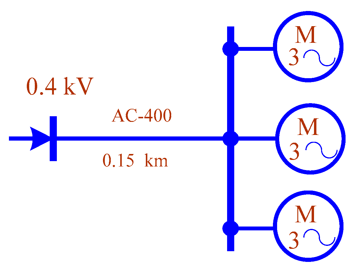
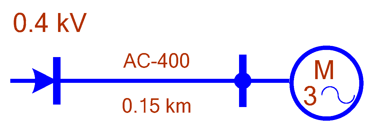
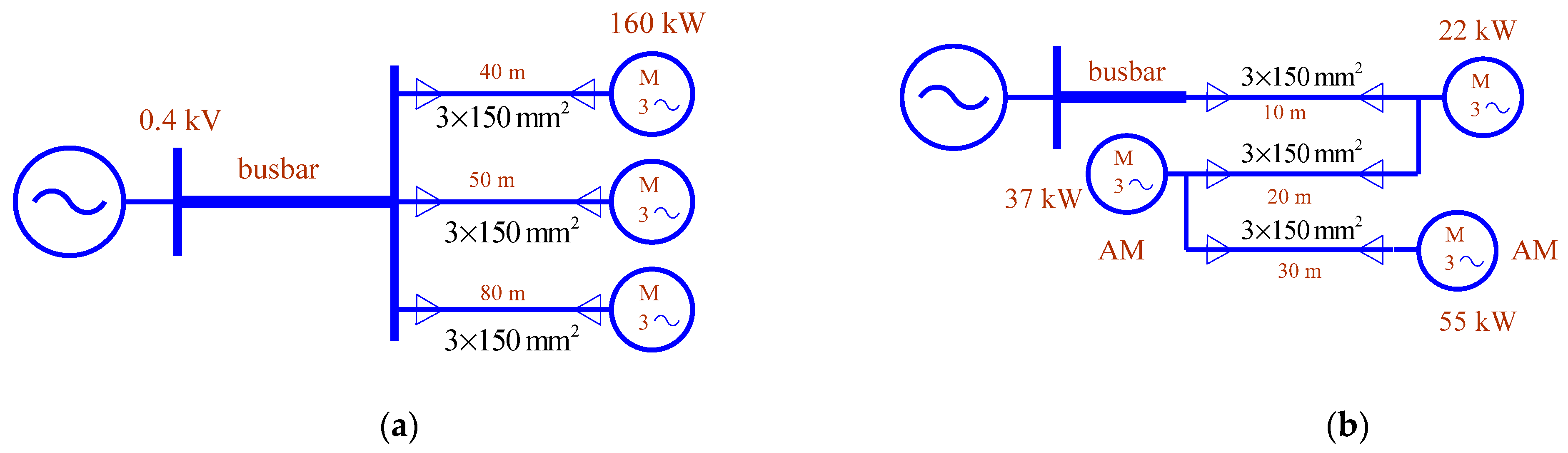
The proposed technique can be used to solve the problem of parameter identification for a group of IMs connected to a node in an electrical network. To confirm this possibility, we performed identification of the AL node, the circuit of which is shown in Figure 7. The IM parameters are summarized in Table 2. The equivalent circuit is shown in Figure 8.
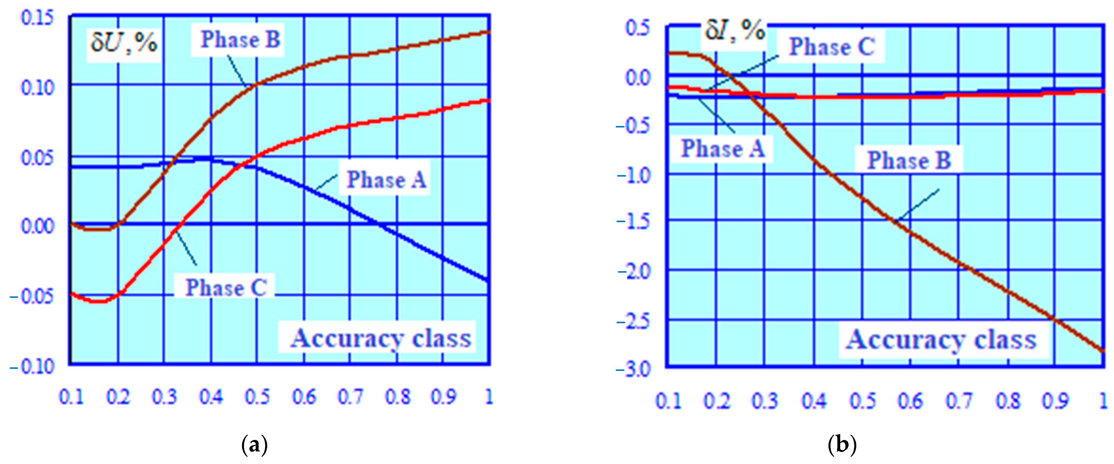
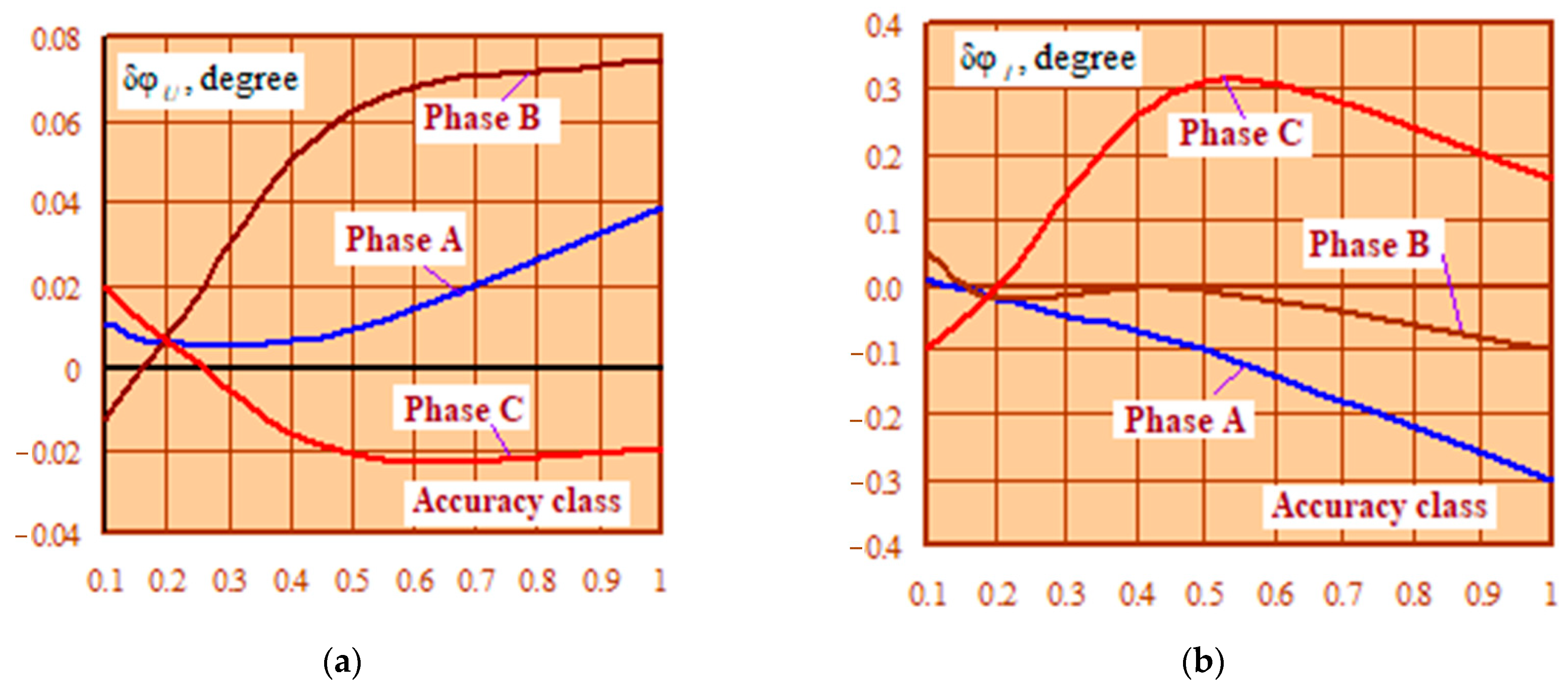
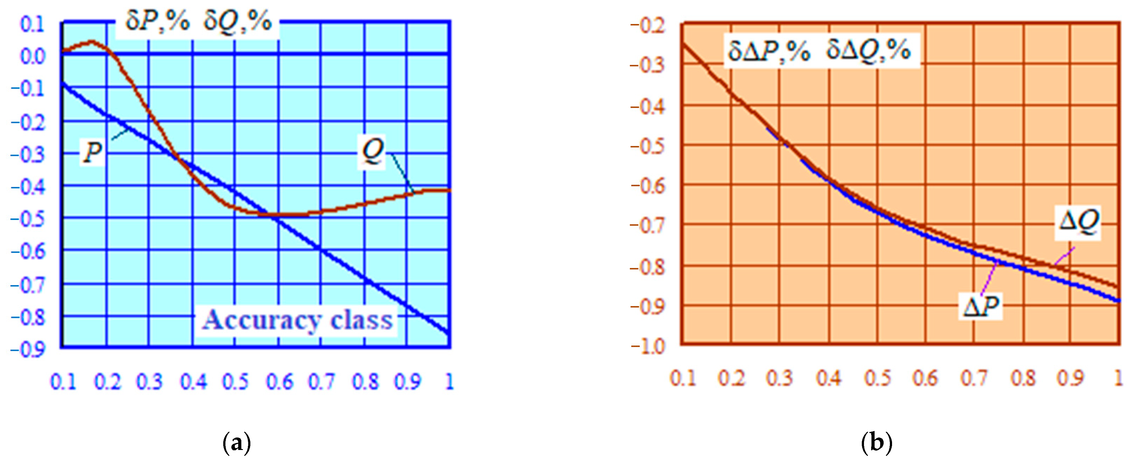
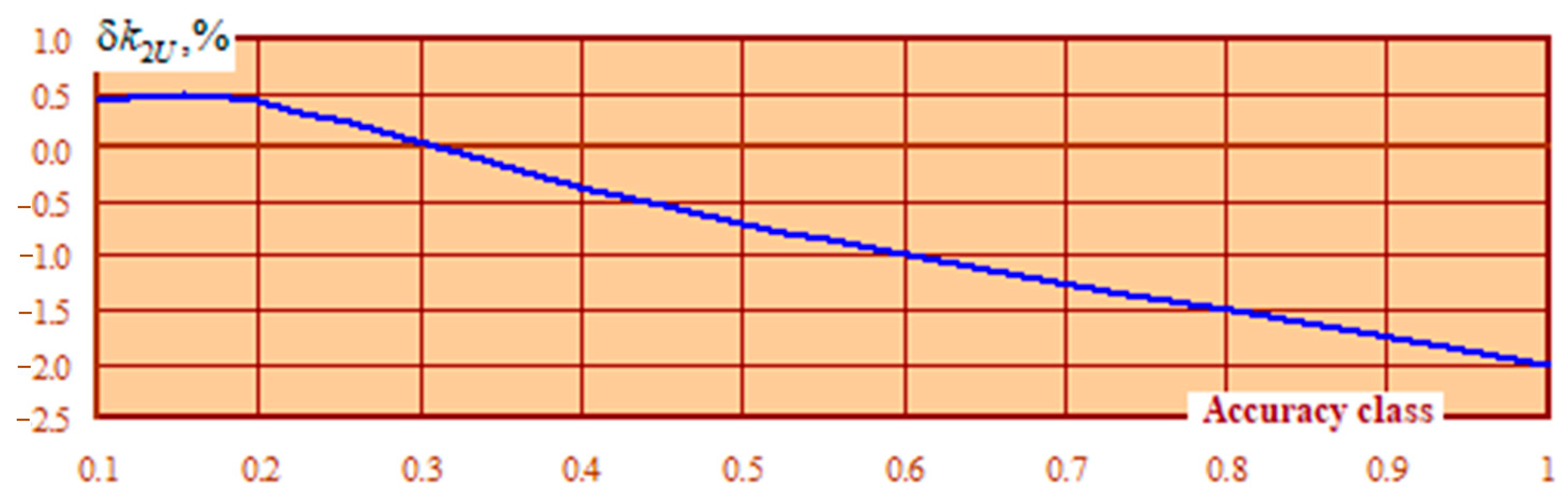
In the process of identification, the slip value was set on the basis of the data for the equivalent IM given in [25]. The load flow analysis errors that arise when using the equivalent model of an asynchronous load node, obtained on the basis of parameter identification, are shown in Figure 9, Figure 10, Figure 11 and Figure 12.
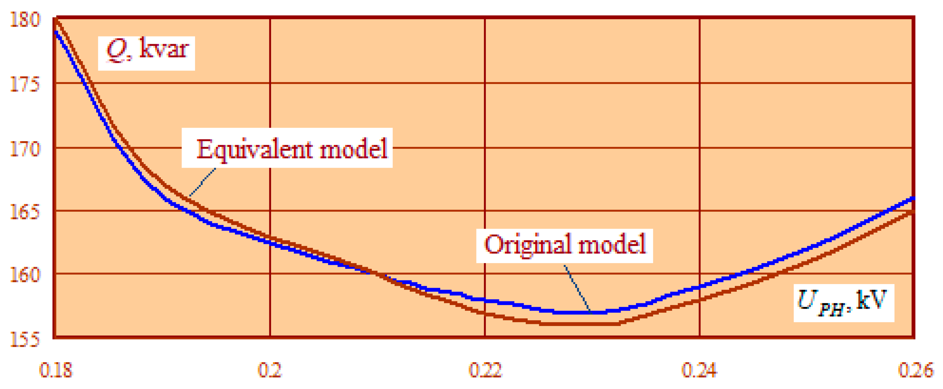
Table 3 and Figure 13 show the static characteristics of and , where stands for active and reactive powers consumed by the AL node; is the phase voltage. These dependencies were plotted for the original and equivalent AL node models. Our analysis of the results thus obtained allows us to conclude that the AL node model, formed on the basis of parameter identification, provides for valid simulation of the asynchronous load node within a wide range of changes in network operating conditions.
The results obtained also allow us to conclude that, with the aid of parameter identification, we can arrive at an equivalent model of an asynchronous load node that provides high accuracy for both balanced and unbalanced load flow analysis. It should be emphasized that the model was validated in a wide range of changing power flow parameters.
The proposed technique is also valid for AL circuits of a more general type, the models of which are shown in Figure 14. In these circuits, induction motors are connected to the buses of the node through cable lines. In addition, the node was powered by a busbar trunking system.
The simulation results are presented in Table 4, which shows that equivalent models with a structure similar to the one presented in Figure 8 provided acceptable accuracy for unbalanced load flow analysis.
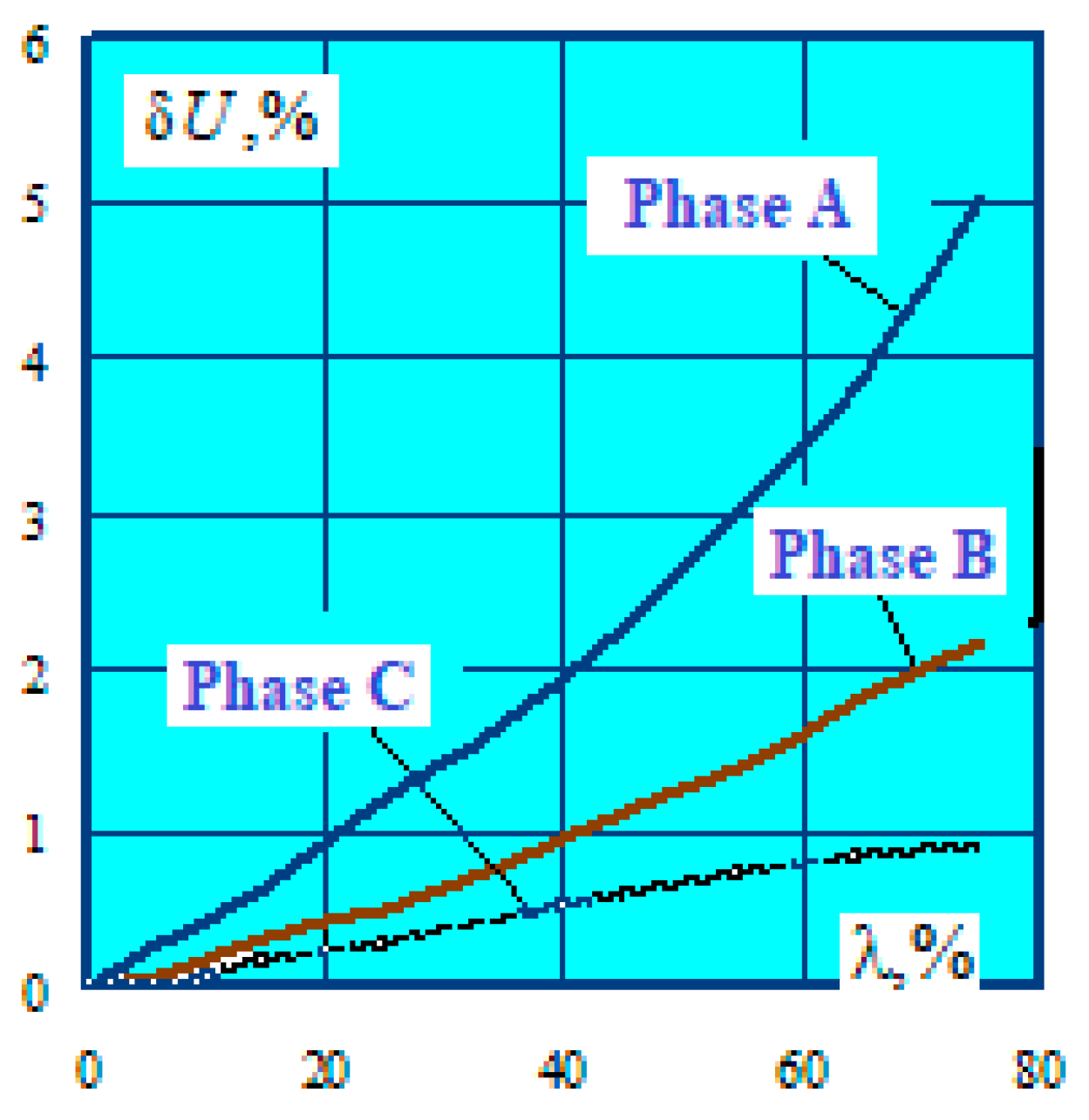
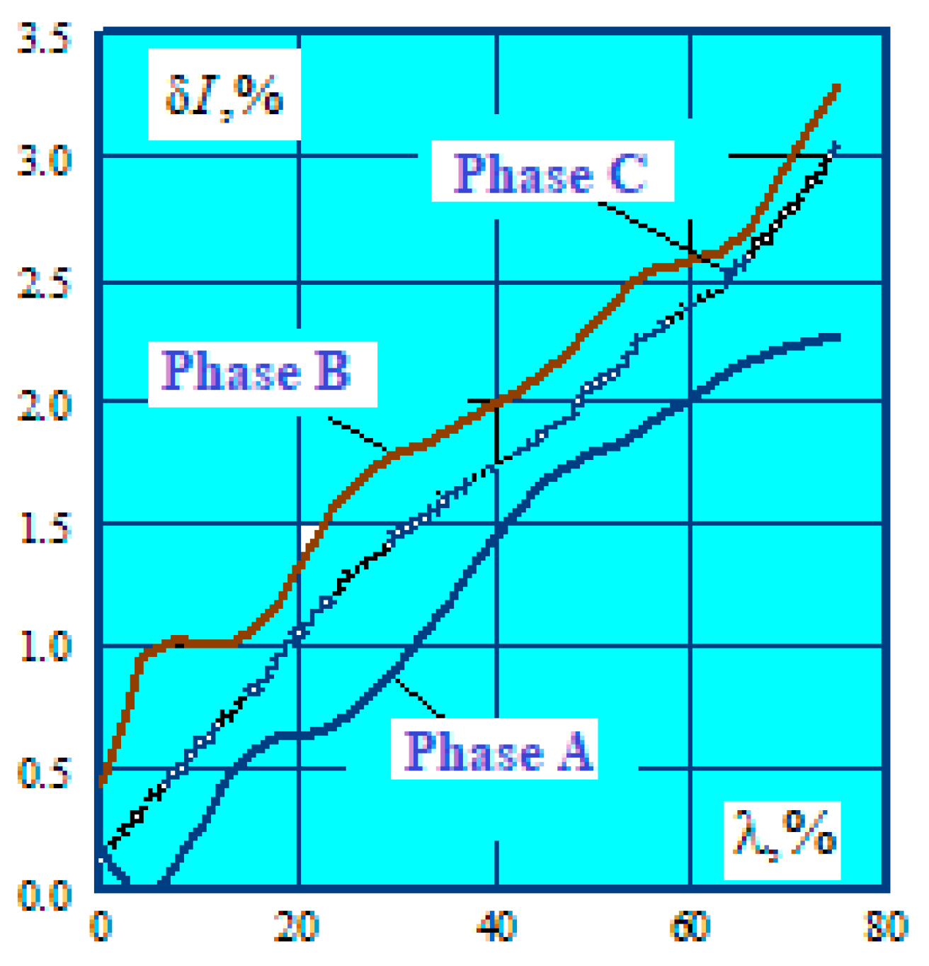
Figure 15 and Figure 16 show the results of parameter identification for the case when, in addition to the IM, a static load was connected to the nodal point of the network, with such a load specified by the amount of power drawn by it. Percentage of stationary load
ranged from 0–80%. Here is the total power of the IM group.
The obtained relationships and attested to the fact that with an increase of the parameter , the errors of load flow analysis using the equivalent IM model increased but remained quite acceptable for practical applications over a sufficiently wide range of variation of .
The following conclusions can be drawn on the basis of the results obtained:
1. The technique of parameter identification of an asynchronous load node allows one to obtain adequate models of IMs that provide high accuracy for balanced load flow analysis. In the numeric example presented in the paper, the calculation error of phase voltage moduli for different motor connection schemes did not exceed 1.5%;
2. If a static load is present at the node, the error of the equivalent model increases; in the numeric example above, when the value of the parameter was equal to 75%, the error of the voltage moduli increased to 5%, and the error of the currents increased to 3.3%.
5. Parameter Identification of Asynchronous Load Nodes with Variable Frequency Drives
At modern production facilities, variable-frequency induction-motor drives equipped with static frequency converters (SFC) are widely used. Therefore, the problem of identifying AL nodes that contain, along with conventional IMs, frequency-controlled asynchronous electric drives that can create harmonic distortions in networks becomes relevant [26]. The technique described above can be used to solve this problem.
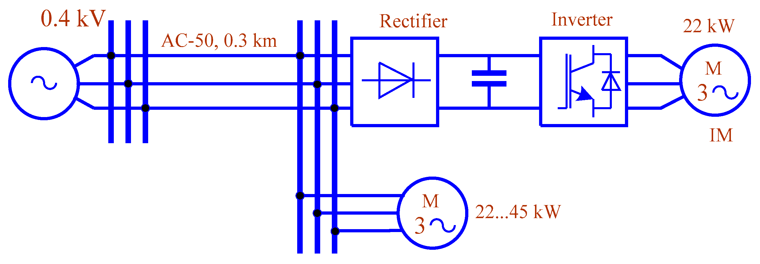
The verification of its efficacy and accuracy in the presence of electric drives at the load node that are equipped with an SFC was carried out for the circuit shown in Figure 17 as follows. Based on the SimPowerSystems MATLAB package, a load node model was generated.
The power of the IM controlled by the SFC was assumed to be 22 kW. The power of the fixed-speed IM ranged from 22 kW to 45 kW. The power ratio was set by the coefficient
where —power of the motor equipped with an SFC; —power of the fixed-speed IM. The power supply system was fed from a source with unbalanced voltage (), which corresponded to real-life conditions that hold true for many facilities connected to district windings of traction substations on mainline AC railroads. The results of the simulation are presented in Table 5.
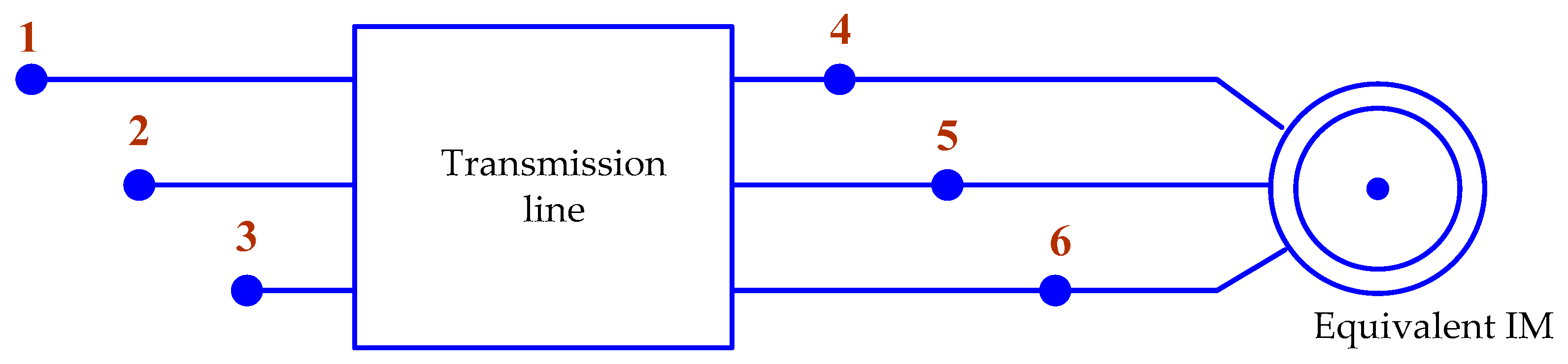
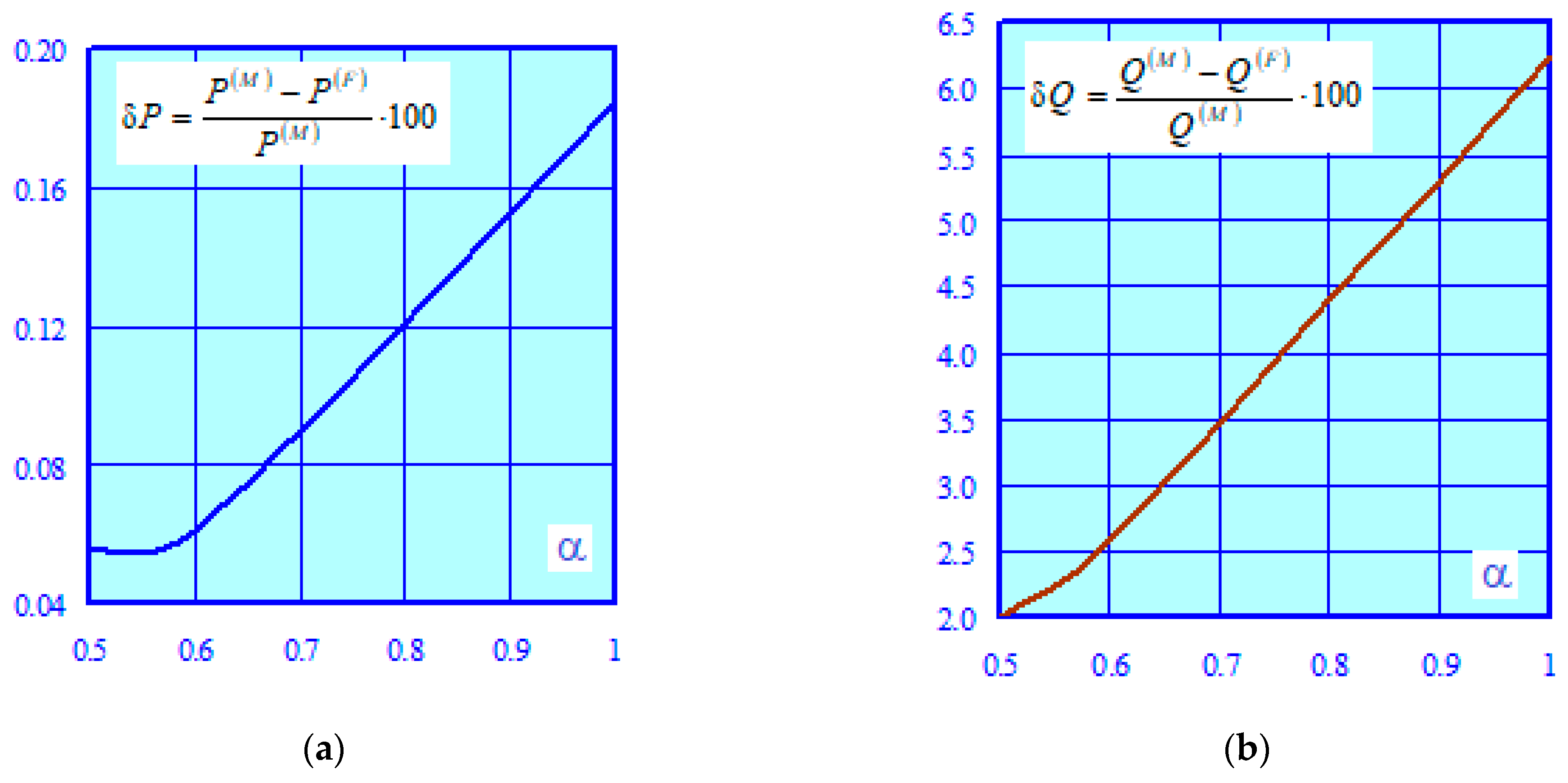
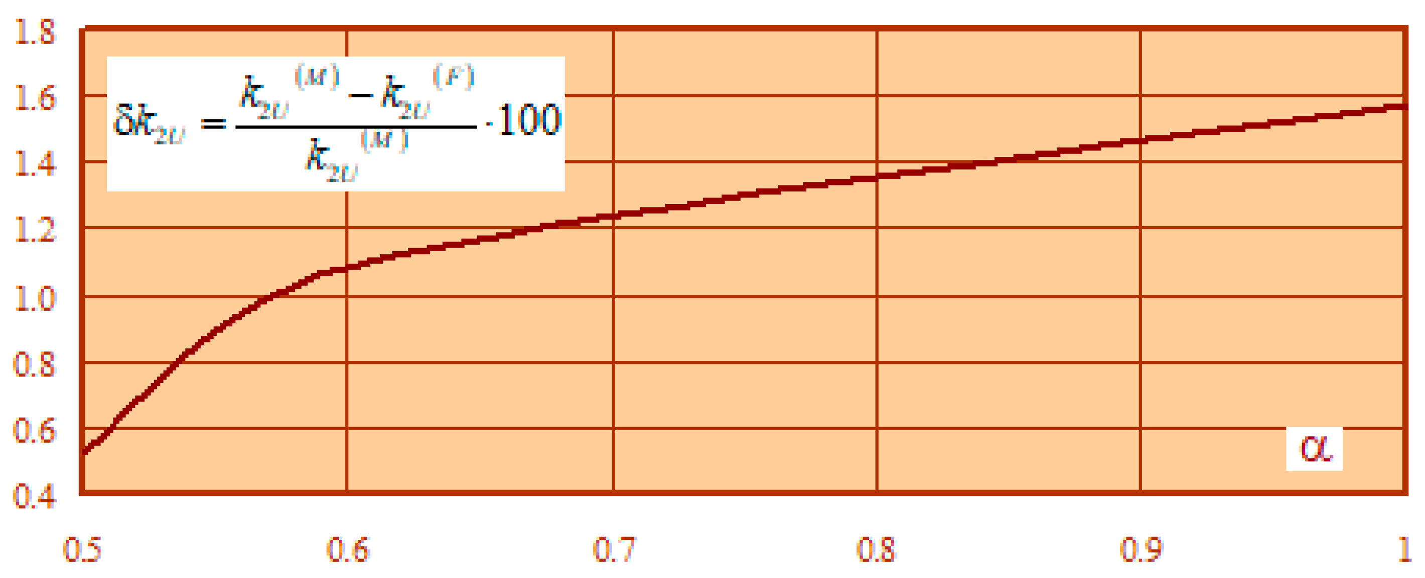
In accordance with the identification technique described above, we determined the parameters of AL equivalent circuits (Table 6). Next, we created a model of the power supply system in the software package Fazonord, in which the load node was represented by an equivalent induction motor (see Figure 18). With the aid of this model, a load flow analysis was performed using the parameters of the AL node obtained as a result of identification. Comparative results of a simulation run in MATLAB and Fazonord are shown in Table 7. Errors in determining the active and reactive powers drawn from the network, as well as the unbalance ratio , are shown in Figure 19 and Figure 20.
In Figure 19 and Figure 20, the index “M” refers to the results obtained using the SimPowerSystems package, and the index “F” refers to the data calculated using the Fazonord software package.
The results obtained allow us to draw the following conclusions:
1. Our technique of parameter identification in the phase frame of reference is based on the substitution of a load node with an equivalent induction motor. The technique allows one to obtain high accuracy in unbalanced load flow analysis in the presence of conventional induction machines and electric motors with variable-frequency drives at the node. The error in determining the unbalance ratio of the negative sequence did not exceed two percent.
2. As the share of static frequency converters at the load node increased, the errors in determining the unbalance ratios also increased but remained within the limits deemed acceptable for solving practical problems;
3. The error in determining the reactive power, which reaches 6.5%, can be explained by differences in approaches to its determination adopted in the MATLAB and Fazonord software systems. In calculations aided by the Fazonord package, only one of its segments was used, which provided the fundamental harmonic for the unbalanced load flow analysis. When using the MATLAB system, the simulation was carried out so as to take into account the non-linear current-voltage characteristics of SFC components, and the reactive power was determined by factoring in the higher harmonics.
The reactive power error can be reduced by additional non-sine load flow modeling using the technique reported in [22]. After determining the higher harmonic voltages, it is possible to recalculate the reactive power, e.g., using the technique of equivalent sine waves.
6. Conclusions
Based on the evidence provided in this study, we can claim we have solved a currently relevant scientific and engineering problem of enhancing the accuracy of modeling unbalanced load flows in electric power systems. Our solution is based on an adequate model of induction motors and a technique of parameter identification for asynchronous loads. The following results were obtained:
1. We have developed a technique for modeling complex load nodes. The technique stands out from other known solutions for its use of the phase frame of reference. Its application scope covers the problems of load dispatching in smart grids;
2. The study has contributed a technique for parameter identification of load nodes. The technique is applicable to the problems of power system load dispatching. A key defining feature of the technique is the structure of the model, which is made up of three sources of current with parameters that are refined in the process of iterative load flow analysis of the power system;
3. We have proposed a technique for the identification of asynchronous load nodes with such asynchronous loads, including electrical drives equipped with static frequency converters;
4. With the aid of the asynchronous load identification models proposed in this paper, it is possible to solve the following practical tasks of electric power system management: increasing the accuracy of load flow modeling; making informed decisions when taking measures to reduce unbalance in power grids; and accounting for the balancing adjustment effect of asynchronous loads.
Author Contributions
Conceptualization, A.K., P.I. and A.A.; methodology, A.K. and K.S.; software A.K.; validation, A.K., A.A., P.I. and K.S.; formal analysis, A.K. and K.S.; investigation, A.K., A.A., P.I. and K.S.; resources, K.S.; data curation, A.K.; writing—original draft preparation, A.K. and K.S.; writing—review and editing, A.K., A.A. and K.S.; visualization, A.A. and P.I.; supervision, A.K. and K.S.; project administration, A.A. and K.S.; funding acquisition, K.S. All authors have read and agreed to the published version of the manuscript.
Funding
The research was carried out within the framework of the state task “Conducting applied scientific research” on the topic “Development of methods, algorithms and software for modeling the modes of traction power supply systems for DC railways and electromagnetic fields at traction substations for AC railways”.
Data Availability Statement
Data sharing not applicable. No new data were created or analyzed in this study. Data sharing is not applicable to this article.
Conflicts of Interest
The authors declare no conflict of interest. The funders had no role in the design of the study; in the collection, analyses, or interpretation of data; in the writing of the manuscript, or in the decision to publish the results.
References
- Afanasyev, A.Y.; Makarov, V.G.; Hannanova, V.N. Identification of three-phase induction motor parameters in the case when initial values of estimates vary in a wide range. Power Eng. Res. Equip. Technol. 2015, 11–12, 87–96. (In Russian) [Google Scholar]
- Rakov, I.V. Experimental study of efficacy of the technique of adaptive identification of electrical parameters of the induction machine with an open-circuit rotor winding under steady-state conditions on the basis of the power balance. Elektrotekhnicheskie I Inf. Kompleks. I Sist. 2022, 18, 63–76. (In Russian) [Google Scholar]
- Nagaitsev, A.L.; Semenov, A.V.; Fedyukov, R.V.; Fishov, A.G.; Chershova, V.O. Online parameter identification of the equivalent circuit and control of load stability. Nauchnye Probl. Transp. Sib. I DAL’NEGO Vost. 2015, 3, 198–203. (In Russian) [Google Scholar]
- Khemliche, M.; Latreche, S.; Khellaf, A. Modelling and identification of the asynchronous machine. In Proceedings of the First International Symposium on Control, Communications and Signal Processing 2004, Hammamet, Tunisia, 21–24 March 2004. [Google Scholar]
- Janisch, G.; Kugi, A.; Kemmetmüller, W. Model calibration strategy for energy-efficient operation of induction machines. IFAC-PapersOnLine 2022, 55, 307–312. [Google Scholar] [CrossRef]
- Bulatov, Y.; Kryukov, A.; Suslov, K. Using Group Predictive Voltage and Frequency Regulators of Distributed Generation Plants in Cyber-Physical Power Supply Systems. Energies 2022, 15, 1253. [Google Scholar] [CrossRef]
- Frolov, M.; Dulov, I.; Yunusova, I. Identification of Asynchronous Motor Parameters in Operational Mode. In Proceedings of the 2019 International Ural Conference on Electrical Power Engineering (UralCon), Chelyabinsk, Russia, 1–3 October 2019. [Google Scholar]
- Sun, Y.; Kang, Z.; Liu, J. Research on Parameter Identification Method of Asynchronous Motor Considering Load Characteristics. In Proceedings of the 2022 IEEE 5th International Electrical and Energy Conference (CIEEC), Nanjing, China, 27–29 May 2022. [Google Scholar]
- Henrotte, F.; Heidt, J.; Hameyer, K. The mathematics of lumped parameter identification in electrical machines. In Proceedings of the 2008 IET 7th International Conference on Computation in Electromagnetics, Brighton, UK, 7–10 April 2008. [Google Scholar]
- Li, Y.M.; Bergmann, C.; Feuvrie, B. An approach of parameter identification for asynchronous machine. In Proceedings of the 1996 IEEE IECON. 22nd International Conference on Industrial Electronics, Control, and Instrumentation, Taipei, Taiwan, 9 August 1996; Volume 3. [Google Scholar]
- Touhami, O.; Fadel, M.; Levi, E.; Sokola, M.; Vukosavic, S.N. A method for magnetizing curve identification in rotor flux oriented induction machines. IEEE Trans. Energy Convers. 2000, 15, 2. [Google Scholar]
- Wang, L.; Deng, X.; Hu, K.; Zhang, X.; Wang, K. A Novel Parameter Identification Method for Induction Motor. In Proceedings of the International Conference on Measuring Technology and Mechatronics Automation, Changsha, China, 13–14 March 2010; Volume 1. [Google Scholar]
- Uzunović, T.; Montoya, F.G.; Osmanović, A.; Arrabal-Campos, F.M.; Alcayde, A.; Eid, A.H.; Šabanović, A. Combining Real-time Parameter Identification and Robust Control Algorithms for Effective Control of Electrical Machines. In Proceedings of the International Conference on Electrical Machines (ICEM), Valencia, Spain, 5–8 September 2022. [Google Scholar]
- Pan, J.; Westwick, D.; Nowicki, E. Flux estimation of induction machines with the linear parameter-varying system identification method. In Proceedings of the Canadian Conference on Electrical and Computer Engineering, Niagara Falls, ON, Canada, 2–5 May 2004; Volume 4. [Google Scholar]
- Liu, Z.; Zheng, Z.; Li, Y.; Peng, L. Parameter identification of nine-phase induction machines with concentrated windings. In Proceedings of the 17th International Conference on Electrical Machines and Systems (ICEMS), Hangzhou, China, 22–25 October 2014. [Google Scholar]
- Košťál, T. Induction machine parameters identification method suitable for self-commissioning. In Proceedings of the XXVI International Scientific Conference Electronics (ET), Sozopol, Bulgaria, 13–15 September 2017. [Google Scholar]
- Košťál, T. Offline induction machine parameters identification suitable for self-commissioning. In Proceedings of the International Conference on Applied Electronics (AE), Pilsen, Czech Republic, 5–6 September 2017. [Google Scholar]
- Heidler, B.; Brune, K.; Doppelbauer, M. High-frequency model and parameter identification of electrical machines using numerical simulations. In Proceedings of the IEEE International Electric Machines & Drives Conference (IEMDC), Coeur d’Alene, ID, USA, 10–13 May 2015. [Google Scholar]
- Sarma, N.; Tuohy, P.; Djurović, S. Condition monitoring of rotating electrical machines. In Encyclopedia of Electrical and Electronic Power Engineering; Elsevier: Amsterdam, Netherlands, 2022; pp. 143–154. [Google Scholar]
- Košt’ál, T. Reducing electrical energy consumption of AHU fans through parameter identification of the drive. In Proceedings of the 3rd International Conference on Intelligent Green Building and Smart Grid (IGBSG), Yilan, Taiwan, 22–25 April 2018. [Google Scholar]
- Siddavatam, R.P.R.; Loganathan, U. Identification of Induction Machine parameters including Core Loss Resistance using Recursive Least Mean Square Algorithm. In Proceedings of the IECON 2019—45th Annual Conference of the IEEE Industrial Electronics Society, Lisbon, Portugal, 14–17 October 2019. [Google Scholar]
- Zakaryukin, V.P.; Kryukov, A.V.; Kong, D.L. Modeling and Parameter Identification of Load Nodes of Electric Power Systems; Irkutsk state transport university: Irkutsk, Russia, 2016; 158p. (In Russian) [Google Scholar]
- Kryukov, A.; Suslov, K.; Van Thao, L.; Hung, T.D.; Akhmetshin, A. Power Flow Modeling of Multi-Circuit Transmission Lines. Energies 2022, 15, 8249. [Google Scholar] [CrossRef]
- Gurevich Yu., E.; Libova, L.E.; Khachatryan, E.A. Load Stability of Electrical Systems; Energoizdat: Moscow, Russia, 1981; 208p. (In Russian) [Google Scholar]
- Deich, A.M. Methods for Identification of Dynamic Objects; Energiya: Moscow, Russia, 1979; 240p. (In Russian) [Google Scholar]
- Kuwałek, P.; Wiczyński, G. Problem of Total Harmonic Distortion Measurement Performed by Smart Energy Meters. Meas. Sci. Rev. 2022, 22, 1–10. [Google Scholar] [CrossRef]
Figure 1.
Positive (a) and negative (b) sequence equivalent circuits.

Figure 2.
Equivalent circuit in the phase frame of reference. (A, B, C—Phase A, Phase B, Phase C, respectively, N—neutral point).
Figure 2.
Equivalent circuit in the phase frame of reference. (A, B, C—Phase A, Phase B, Phase C, respectively, N—neutral point).

Figure 3.
Synchronized measurements.

Figure 4.
On the problem of structural identification of load nodes.

Figure 5.
A set of problems for identifying load nodes in an electric power system.

Figure 6.
Identification errors.

Figure 7.
Original circuit.

Figure 8.
Equivalent circuit.

Figure 9.
Errors in determining the moduli of voltages (a) and currents (b).

Figure 10.
Errors in determining phases of voltages (a) and currents (b).

Figure 11.
Errors in determining the active and reactive power consumed by the AL node (a), and power losses in the transmission line (b).
Figure 11.
Errors in determining the active and reactive power consumed by the AL node (a), and power losses in the transmission line (b).

Figure 12.
Errors in determining the unbalance ratio in the negative sequence.

Figure 13.
Static reactive power characteristic.

Figure 14.
Models of AL node circuits (a)—first type of connection, (b)—second type of connection).

Figure 15.
Relationship .

Figure 16.
Relationship .

Figure 17.
Network circuit.

Figure 18.
Load node model formed based on identification results (1–6—numbers of nodes).

Figure 19.
Errors of active (a) and reactive (b) powers as functions of the parameter.

Figure 20.
Unbalance ratio error as a function of the parameter α.


Table 1.
Parameters of the approximation of the relationship .
| Parameter | 750 rpm | 1000 rpm | 1500 rpm | 3000 rpm |
|---|---|---|---|---|
| , per unit | 1.4 | 1.7 | 2.0 | 2.3 |
| , per unit | 1.0 | 1.2 | 1.4 | 1.4 |
| , kW−1 | 0.04 | 0.05 | 0.045 | 0.04 |
Table 2.
Parameters of the nodal IM.
| IM No. | Efficiency, % | |||||||
|---|---|---|---|---|---|---|---|---|
| 1 | 45 | 92 | 0.9 | 0.017 | 0.222 | 0.034 | 0.16 | 4.6 |
| 2 | 110 | 92.5 | 0.9 | 0.019 | 0.282 | 0.048 | 0.21 | 4.9 |
| 3 | 160 | 93.5 | 0.91 | 0.017 | 0.257 | 0.045 | 0.19 | 4.6 |
Table 3.
Static load characteristics.
| Original Model | Equivalent Model | Discrepancy | ||||
|---|---|---|---|---|---|---|
| P | Q | P | Q | |||
| kW | kVar | kW | kVar | % | % | |
| 0.18 | 325 | 179 | 324 | 180 | 0.19 | −0.72 |
| 0.19 | 325 | 166 | 324 | 167 | 0.19 | −0.31 |
| 0.21 | 325 | 160 | 324 | 160 | 0.19 | −0.01 |
| 0.22 | 325 | 158 | 324 | 157 | 0.19 | 0.23 |
| 0.23 | 325 | 157 | 324 | 156 | 0.19 | 0.43 |
| 0.24 | 325 | 159 | 324 | 158 | 0.19 | 0.61 |
| 0.25 | 325 | 162 | 324 | 161 | 0.19 | 0.77 |
| 0.26 | 325 | 166 | 324 | 165 | 0.19 | 0.90 |
Table 4.
Identification errors.
| Parameters | Error, % | |
|---|---|---|
| Circuit of Figure 1a | Circuit of Figure 1b | |
| –0.04 | −1.51 | |
| –0.05 | −0.05 | |
| 0.00 | 0.00 | |
| 2.56 | 0.33 | |
| 8.71 | 6.96 | |
| 1.88 | −2.08 | |
| , % | 3.26 | 0.25 |
| , % | 2.82 | −0.32 |
| 2.40 | 3.21 | |
| 3.94 | 4.09 | |
| –0.18 | −0.17 | |
Table 5.
Voltages and currents at load node buses.
| α | Voltages | Currents | ||||
|---|---|---|---|---|---|---|
| Phase A | Phase B | Phase C | Phase A | Phase B | Phase C | |
| Modulus, B Angle, Deg. | Modulus, B Angle, Deg. | Modulus, B Angle, Deg. | Modulus, A Angle, Deg. | Modulus, A Angle, Deg. | Modulus, A Angle, Deg. | |
| 1 | 215.4 27.8 | 209.2 –91.3 | 215.5 149.6 | 79.97 2.1 | 69.59 –102.8 | 90.59 134.7 |
| 0.6 | 209.7 27.5 | 203.8 –91.5 | 209.1 149.4 | 105.7 7.5 | 96.52 –98.9 | 120.7 137.6 |
| 0.5 | 204.7 27.4 | 198.7 –91.7 | 204.2 149.3 | 125.3 1.7 | 113.9 –107.9 | 137.8 130.7 |
Table 6.
Equivalent circuit parameters.
| α | |||||
|---|---|---|---|---|---|
| 1 | 0.056 | 0.224 | 0.430 | 0.250 | 12.005 |
| 0.6 | 0.04 | 0.023 | 0.315 | 0.216 | 8.991 |
| 0.5 | 0.034 | 0.237 | 0.313 | 0.236 | 7.566 |
Table 7.
Parameters characterizing the load flow of the load node.
| α | P, kW | Q, kVar | ||||
|---|---|---|---|---|---|---|
| MATLAB | Fazonord | MATLAB | Fazonord | MATLAB | Fazonord | |
| 1 | 48.76 | 48.85 | 16.52 | 15.49 | 1.90 | 1.93 |
| 0.6 | 65.29 | 65.25 | 15.88 | 15.47 | 1.84 | 1.82 |
| 0.5 | 71.58 | 71.54 | 27.11 | 26.57 | 1.90 | 1.89 |
Disclaimer/Publisher’s Note: The statements, opinions and data contained in all publications are solely those of the individual author(s) and contributor(s) and not of MDPI and/or the editor(s). MDPI and/or the editor(s) disclaim responsibility for any injury to people or property resulting from any ideas, methods, instructions or products referred to in the content. |
© 2023 by the authors. Licensee MDPI, Basel, Switzerland. This article is an open access article distributed under the terms and conditions of the Creative Commons Attribution (CC BY) license (https://creativecommons.org/licenses/by/4.0/).
Share and Cite
MDPI and ACS Style
Kryukov, A.; Suslov, K.; Ilyushin, P.; Akhmetshin, A. Parameter Identification of Asynchronous Load Nodes. Energies 2023, 16, 1893. https://0-doi-org.brum.beds.ac.uk/10.3390/en16041893
AMA Style
Kryukov A, Suslov K, Ilyushin P, Akhmetshin A. Parameter Identification of Asynchronous Load Nodes. Energies. 2023; 16(4):1893. https://0-doi-org.brum.beds.ac.uk/10.3390/en16041893
Chicago/Turabian StyleKryukov, Andrey, Konstantin Suslov, Pavel Ilyushin, and Azat Akhmetshin. 2023. "Parameter Identification of Asynchronous Load Nodes" Energies 16, no. 4: 1893. https://0-doi-org.brum.beds.ac.uk/10.3390/en16041893
Note that from the first issue of 2016, this journal uses article numbers instead of page numbers. See further details here.