
An Overview of Complex Instability Behaviors Induced by Nonlinearity of Power Electronic Systems with Memristive Load


State Key Laboratory of Electrical Insulation and Power Equipment, School of Electrical Engineering, Xi’an Jiaotong University, Xi’an 710049, China
*
Author to whom correspondence should be addressed.
Energies 2023, 16(6), 2528; https://0-doi-org.brum.beds.ac.uk/10.3390/en16062528
Submission received: 29 January 2023
/
Revised: 27 February 2023
/
Accepted: 6 March 2023
/
Published: 7 March 2023
(This article belongs to the Special Issue Trends and Prospects in Analysis and Control of Power Electronics)
Abstract
:The proposal of the memristor, considered as the fourth basic circuit element, suggests a new possibility for the design of high-performance power electronic systems. However, it also brings new challenges. At present, more and more electrical equipment and systems have demonstrated that their external characteristics can exhibit “8”-shaped hysteresis loops and can be regard as memristive equipment and systems. In order to satisfy the requirements of controllability, flexibility, efficiently, and so on, most memristive equipment and systems are not directly connected to the power grid but instead obtain their own required powering through various forms of power electronic converters. Note that memristive loads are distinctive and demonstrate unique nonlinear behaviors. Similarly, there can be nonlinearity from the resistor (R), inductor (L), or capacitor (C) load, but there is no combination of only R, L, and C that could produce memristive characteristics. In particular, the memristance of memristive devices changes continuously during the operation process; in addition, practical power electronic systems composed of memristive devices and power supplies have strong nonlinear characteristics, which are more likely to result in various complex behaviors and are not conducive to the stable operation of the systems. Therefore, exploring complex instability behaviors of power electronic systems with strong nonlinearity in depth is necessary for better protection and utilization of memristive devices. This paper provides an outline of the status of research on complex behaviors of power electronic systems with memristive load; it is expected to provide guidance for the study of complex behavior of strongly nonlinear systems.
1. Introduction
As early as the 1970s, the memristor, describing the relationship between charge and flux, has been assumed theoretically based on the completeness principle of the basic circuit variable combinations by Professor L. O. Chua from the University of California, Berkeley [1]. Additionally, the mathematical model and electromagnetic interpretation of the memristor is defined in [1]. However, because memristive devices have not been found in practice, research on memristors and their characteristics has not attracted the attention of scientific and industrial circles for a long time. In 2008, the HP Information and Quantum Systems Laboratory reported that the physical memristor had been realized for the first time [2]. This major breakthrough shocked the international field of electrical and electronic technology. Since then, an increasing number of researchers have begun to keep a watchful eye on the study of memristors and their characteristics. With the deepening of the research, fruitful achievements have been made in the realization of the memristor, the characteristic analysis of memristive circuits, and the dynamic behavior research of the memristor. So far, due to its unique memristive characteristics, the memristor has significant application value in communication engineering [3,4,5,6], biomedicine [7,8,9,10], artificial intelligence [11,12,13,14], information storage [15,16,17,18], etc. At the same time, the memristor can provide new possibilities for the realization of high-performance power electronics systems; furthermore, it has gradually received close attention in the field of electrical and power electronic engineering [19,20,21,22]. Therefore, it is valuable to study the stable operation of the power electronic supply system with memristive load for promoting the practical application and development of the memristor. Besides inductors, capacitors, and resistors, the memristor is known as the fourth basic circuit element due to its unique memristive characteristics that cannot be achieved by existing inductors, capacitors, resistors, and their combinations. The advent of the memristor offers a vast space for development of circuit design. At present, more and more electrical equipment has been proved to exhibit typical memristive characteristics under AC excitation. The power electronic circuit can provide AC electric energy required by memristive electrical equipment, which is an important power supply for the memristive load. The system composed of a power electronic circuit supplying memristive load belongs to the strong nonlinear system on account of the joint influence of nonlinear load and switching devices. It is very important to study the mechanism of unstable behaviors occurring in the power electronic system with memristive load to ensure the system is operating stably.
The remainder of this article is organized as follows: reviews of memristors and memristive characteristics are introduced in Section 2; reviews of power electronic systems and their complex behaviors are investigated in Section 3; the importance and necessity of complex behaviors in power electronic systems are stated in Section 4; finally, in Section 5, the conclusion is given.
2. Reviews of Memristors and Memristive Characteristics
2.1. Concept and Characteristics of the Memristor
In 1971, the conception of the memristor was proposed for the first time to increase the number of basic circuit elements to four, thus improving the circuit theoretical system [1]. The relationship structure of the four basic elements is shown in Figure 1 [23].
For electrical theory, current (i), voltage (v), flux (φ), and charge (q) are four basic variables used to describe the characteristics of circuits and components. These four basic variables can construct six different functional relationships and define four basic circuit elements, namely the resistor (defined by the relationship between v and i), the capacitor (defined by the relationship between q and v), the inductor (defined by the relationship between φ and i), and the memristor (defined by the relationship between q and φ). Thus, the intrinsic relationships that exist between the four basic variables and the four basic circuit elements can be summarized as
(1) Resistor:
(2) Capacitor:
(3) Inductor:
(4) Memristor:
- Concept of the memristor
As the fourth basic circuit element, the memristor is used to describe the relationship between charge and flux. Since the memristance or memductance of the memristor is related to one or more internal state variables as well as the amount of all charges flowing through it, it has unique memristive characteristics. Additionally, these memristive characteristics cannot be achieved by the other three basic elements or any combination thereof. The memristor is a two-terminal element defined based on Ohm’s law and can be classified into two types: the flux-controlled memristor and the charge-controlled memristor [1].
As shown in Table 1, when Equation (4) is given by a single-value function of the charge, this memristor is called a charge-controlled memristor, which is also known as a current-controlled memristor [1]. In Figure 2a, the characteristic curve of the charge-controlled memristor is a curve passing through the origin in the q-φ plane. M(q) is the memristance of the charge-controlled memristor, which is a nonlinear function about q(t) and whose unit is the ohm (Ω). Conversely, when Equation (4) is expressed by a single-value function of the flux, this memristor is named a flux-controlled memristor, which is also known as the voltage-controlled memristor [1]. In Figure 2b, the characteristic curve of the flux-controlled memristor is a curve passing through the origin in the φ-q plane. W(φ) is the memductance of the flux-controlled memristor, which is a nonlinear function about φ(t) and whose unit is the siemens (S).
- Volt–ampere characteristic of memristors
As given in Table 2, assuming that the reference directions of the memristive voltage v(t) and the memristive current i(t) are positively correlated, the volt–ampere relationship between the memristive current i(t) flowing through the charge-controlled memristor and its memristive voltage v(t) can be given as

Table 2.
Characteristics of the memristor.
| Item | Charge-Controlled Memristor | Flux-Controlled Memristor |
|---|---|---|
| Control variable | i(t) | v(t) |
| Expression | ||
| Characteristic curve | Figure 3a | Figure 3b |
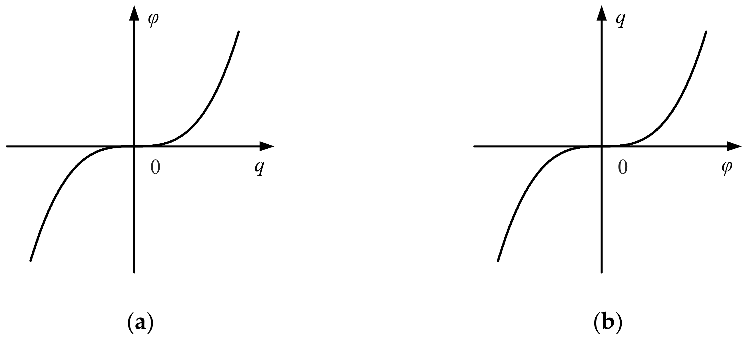
Figure 3.
Volt–ampere characteristics of the memristor. (a) Current-controlled memristor (or charge-controlled memristor); (b) voltage-controlled memristor (or flux-controlled memristor).
Figure 3.
Volt–ampere characteristics of the memristor. (a) Current-controlled memristor (or charge-controlled memristor); (b) voltage-controlled memristor (or flux-controlled memristor).

Note that if the reference directions of the memristive voltage v(t) and the memristive current i(t) are negatively correlated, a negative sign should be placed on the right-hand side of (5). In (5), the internal state variable q(t) of the charge-controlled memristor is the integral of the memristive current i(t). The volt–ampere characteristic curve of the charge-controlled memristor is shown in Figure 3a. One can obtain from Figure 3a that the memristive voltage v(t) of the charge-controlled memristor is a double-valued function of the memristive current i(t) except for the origin.
Accordingly, the reference directions of the memristive voltage v(t) and the memristive current i(t) are positively correlated; the relationship between the memristive voltage v(t) at both ends of the flux-controlled memristor and its memristive current i(t) can be given as
While the reference directions of the memristive voltage v(t) and the memristive current i(t) are negatively correlated, a negative sign should be placed on the right-hand side of (6). In (6), the internal state variable φ(t) of the flux-controlled memristor is the integral of the memristive voltage v(t). The characteristic curve of the flux-controlled memristor is displayed in Figure 3b. In Figure 3b, the memristive current i(t) of the flux-controlled memristor is a double-valued function of the memristive voltage v(t) except for the origin [24].
The charge-controlled memristor given in Figure 3a is chosen as an example to illustrate the active and passive properties of the memristor. The immediate power consumed by the charge-controlled memristor can be expressed as
Setting that t ≥ t0, the energy flowing into the charge-controlled memristor from t0 to t is
If the characteristic curve of the charge-controlled memristor displayed in Figure 2a is monotone rising, and its flux φ is a single-valued function of the charge q, then the charge-controlled memristor is passive and is called a passive memristor. If the characteristic curve of the charge-controlled memristor, which is described in Figure 2a, is non-monotone rising, and its memristive value may become negative in the range of charge q, then the charge-controlled memristor is active and is called an active memristor.
- General definition of a memristor
As shown in Table 3, the instant port current i(t) and the voltage v(t) of the memristor follow Ohm’s law. A general definition of the memristor is introduced in reference [1]. A current-controlled memristor is given as
where x is the state variable defined by the n-dimensional correlation state equation, and x = (x1, x2,…, xn) Rn; M is a continuous function about x and is called the memristance. Note that the state equation of the current-controlled memristor is a function of i(t).
A voltage-controlled memristor can be given as
where x is the state variable defined by the n-dimensional correlation state equation, and x = (x1, x2,…, xn) Rn; W is continuous function about x and is called the memductance. Note that the state equation of the voltage-controlled memristor is a function of v(t).
According to (9) and (10), an ideal current-controlled memristor is described as
Equation (11) can be equivalent to
and
where C1 represents the arbitrary constant about the initial state of an ideal current-controlled memristor.
An ideal voltage-controlled memristor is given as
Equation (14) can be equivalent to
and
where C2 represents the arbitrary constant about the initial state of an ideal voltage-controlled memristor.
In 1976, the conception of the memristor was further developed to the general memristive system. As indicated in [25], the time-invariant n-order u-controlled memristive system, also known as the generalized memristive system, is given as
where u is the input variable; y is the output variable; x is the n-dimensional vector of the inside state variable; ẋ is time derivative of the state vector; g is the continuous scalar function, that is Rn × R × R→R; f is n-dimensional continuous vector function, that is Rn × R × R→Rn.
For any initial state x0 Rn, the state Equation (17) has a corresponding particular solution. When the input variable u of the (17) is i(t), the system is called the generalized current-controlled memristive system.
- Essential characteristics of memristors
In 2013, the theory about memristors was further improved. As indicated in [26], three basic characteristics to identify the memristive elements and systems are provided. If a device or system satisfies the three basic characteristics described in Figure 4, it belongs to a memristive element or system.
(1) When a bipolar periodic excitation signal is used to motivate a device or system whose volt–ampere characteristic curve takes the form of an “8”-shaped hysteresis loop, its response is periodic;
(2) When the frequency of the bipolar periodic excitation signal exceeds a certain threshold value, the sidelobe region of the “8”-shaped pinched hysteresis loop cuts down with increasing excitation frequency;
(3) When the bipolar periodic excitation frequency is infinite, the “8”-shaped pinched hysteresis loop is compressed to a single-valued function.
2.2. Research Actuality of Memristors
2.2.1. Memristor Model
Currently, the realization ways of memristors are divided into the physical model memristors based on metallic materials, the mathematical model memristors based on discrete components, as well as the verified existing devices and systems with memristive characteristics.
- Physical model memristors
In 2008, Hewlett-Packard Information and Quantum Systems Laboratory successfully realized the first physical memristor in a nanofilm based on titanium dioxide (TiO2) material [2]. This is a major breakthrough and attracted widespread attention from researchers. So far, physical model memristors based on different metallic materials have been fabricated successfully, such as spintronics memristors [27,28,29,30], light-emitting memristors [31,32,33], ferroelectric tunneling memristors [34,35,36,37], multiferroic metal memristors [38,39,40], tantalum oxide memristors [41,42,43], silicon nitride memristors [44,45,46,47], and so on. However, the structures of physical model memristors are complicated, and their fabrication cost are high. Moreover, their theoretical models are generally complex or do not have specific mathematical relationships, leading to fewer results of theoretical analysis and application experiments based on physical device model memristors.
- Mathematical model memristors
The circuit simulation and equivalent circuit realization of the mathematical model memristor are the basis of conducting research on memristive characteristics and their application. To this end, more and more mathematical model memristors described by different nonlinear functions have been proposed and analyzed [48,49,50,51,52], as shown in Table 4, among which the mathematical model memristors based on quadratic and cubic nonlinear functions have also been widely recognized by researchers and applied to study the characterization and application of basic memristive circuits.
Table 4.
Existing memristor emulators.
| Item | [48] | [49] | [50] |
|---|---|---|---|
| Memristor | The cubic nonlinear flux-controlled memristor | The piecewise-quadratic flux-controlled memristor | The cubic polynomial flux-controlled memristor |
| Mathematical model | |||
| Memductance | |||
| Characteristic curve | Figure 5 | Figure 6 | Figure 7 |
| Maximum operation frequency | 500 Hz | 1.0 kHz | 15 kHz |
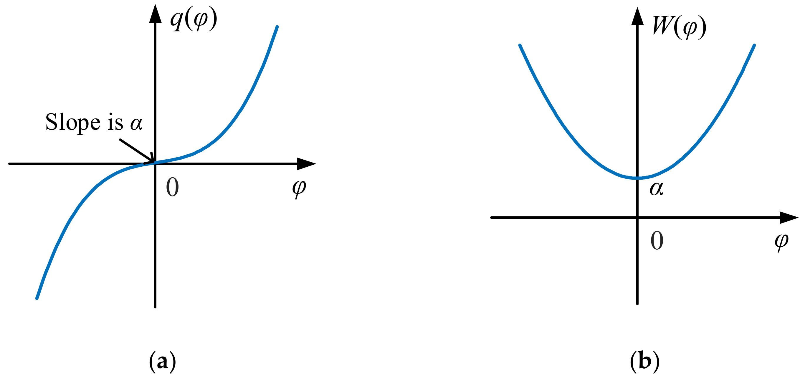
Figure 5.
Characteristic curves of the cubic nonlinear flux-controlled memristor. (a) φ-q(φ); (b) φ-W(φ).
Figure 5.
Characteristic curves of the cubic nonlinear flux-controlled memristor. (a) φ-q(φ); (b) φ-W(φ).

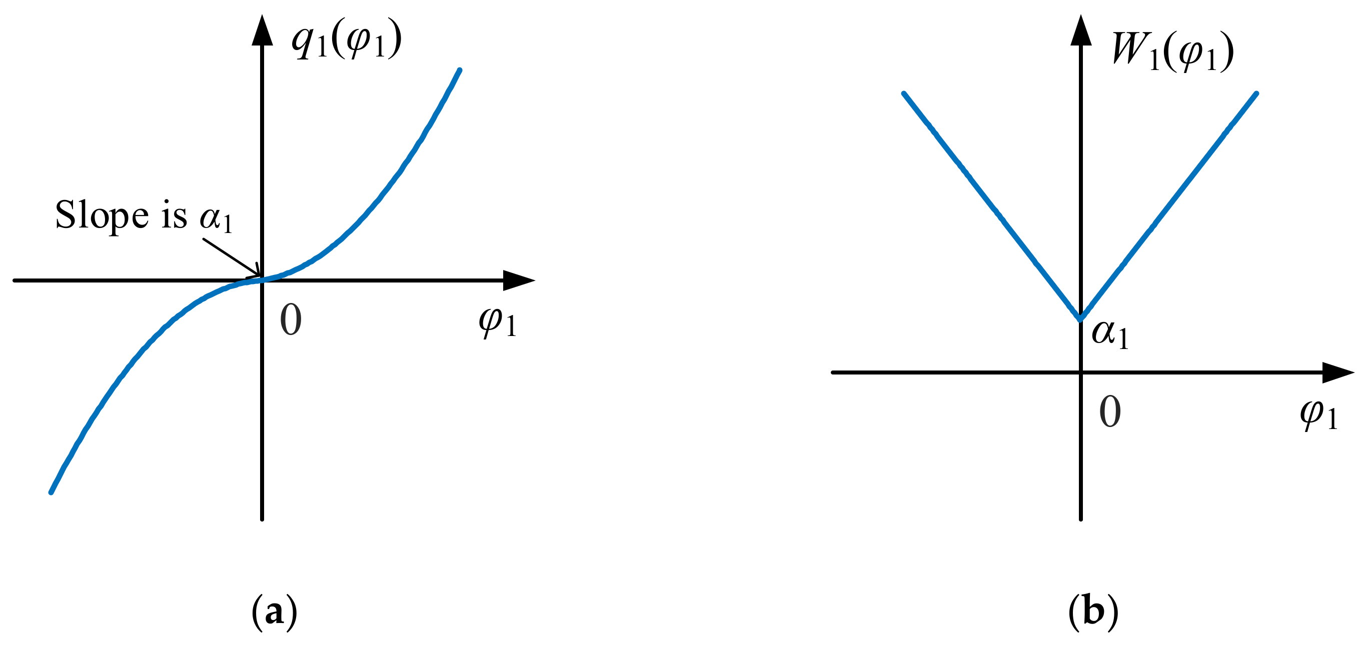
Figure 6.
Characteristic curves of the piecewise-quadratic flux-controlled memristor. (a) φ1-q1(φ); (b) φ1-W1(φ).
Figure 6.
Characteristic curves of the piecewise-quadratic flux-controlled memristor. (a) φ1-q1(φ); (b) φ1-W1(φ).

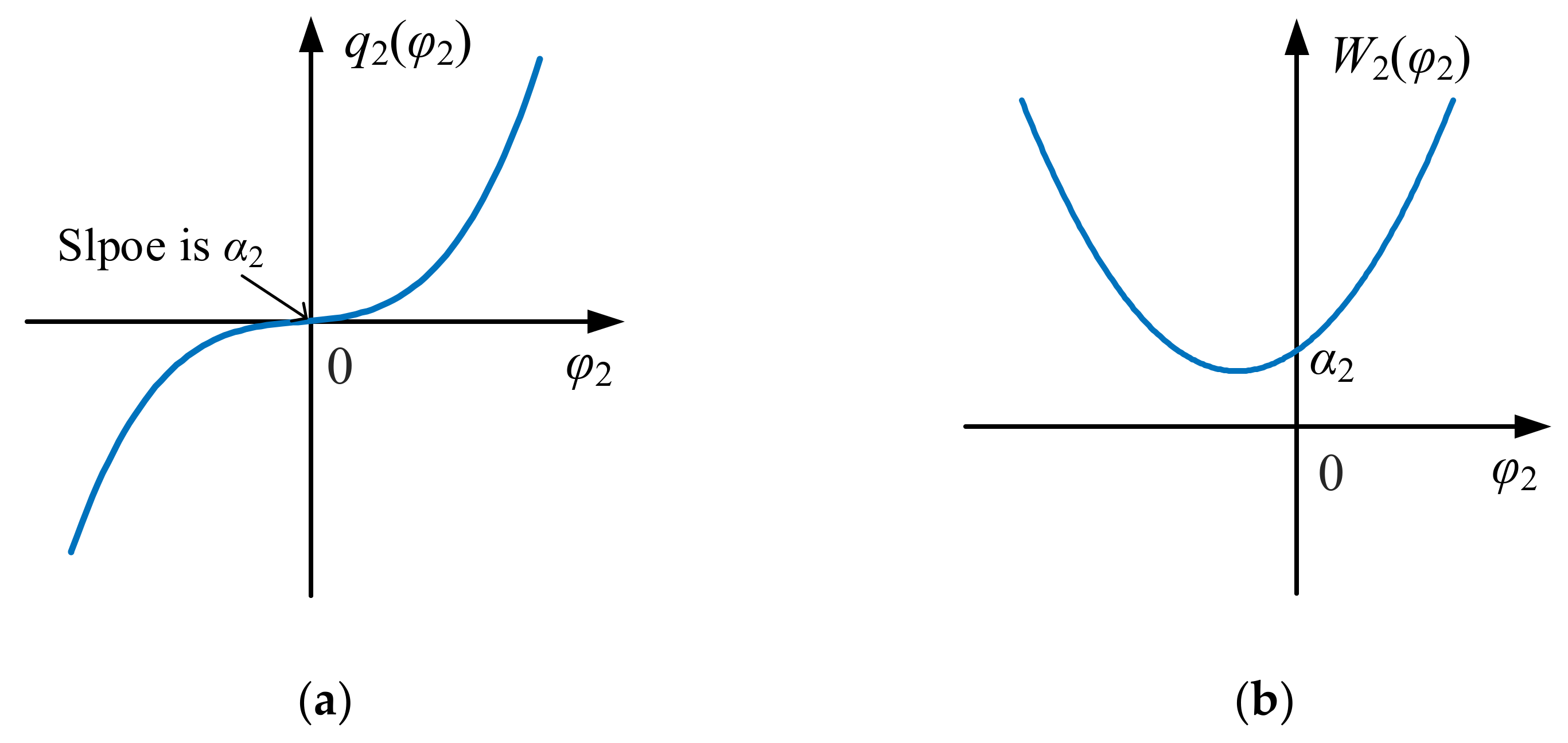
Figure 7.
Characteristic curves of the cubic polynomial flux-controlled memristor. (a) φ2-q2(φ); (b) φ2-W2(φ).
Figure 7.
Characteristic curves of the cubic polynomial flux-controlled memristor. (a) φ2-q2(φ); (b) φ2-W2(φ).

In 2010, B. Muthswamy constructed a flux-controlled memristive equivalent circuit, which is described by the smooth continuous cubic nonlinear function and implemented using discrete components [48]. The mathematical model of the cubic nonlinear flux-controlled memristor is expressed as
where α and β are positive numbers and are memristive parameters of the cubic nonlinear flux-controlled memristor.
The memductance of the cubic nonlinear flux-controlled memristor can be given as
The φ-q(φ) curve described by (18) is shown in Figure 5a, and the φ-W(φ) curve described by (19) is shown in Figure 5b.
In 2011, B. C. Bao et al. presented the piecewise-quadratic flux-controlled memristor, and this memristor is implemented via using existing discrete components [49]. Its mathematical model is given as
where α1 and β1 are memristive parameters of the piecewise-quadratic flux-controlled memristor; they are positive numbers.
The memductance of the piecewise-quadratic flux-controlled memristor can be given as
The φ1-q1(φ) curve described by (20) is shown in Figure 6a, and the φ1-W1(φ) curve described by (21) is shown in Figure 6b.
In order to improve the cubic nonlinear flux-controlled memristor (18), in 2015, W. Liu et al. proposed a cubic polynomial flux-controlled memristor [50]; its mathematical model can be given as
where α2 and β2 are memristive parameters of the cubic polynomial flux-controlled memristor; they are positive numbers.
The memductance of the cubic polynomial flux-controlled memristor is
The φ2-q2(φ) curve described by (22) is shown in Figure 7a, and the φ2-W2(φ) curve described by (23) is shown in Figure 7b.
- Memristive equipment and systems
Some existing power devices and systems have been verified to have memristive characteristics. Research results have shown that the earliest artificial memristive power device was the carbon arc lamp, invented by the British scientist Humphry Davy in 1801 [53]. Then, Gaurav et al. pointed out that the first generation of radio detectors (metal detectors) were typical memristive devices [54], while a variety of gas discharge lamps have been successively proved to be memristive devices [55,56,57].
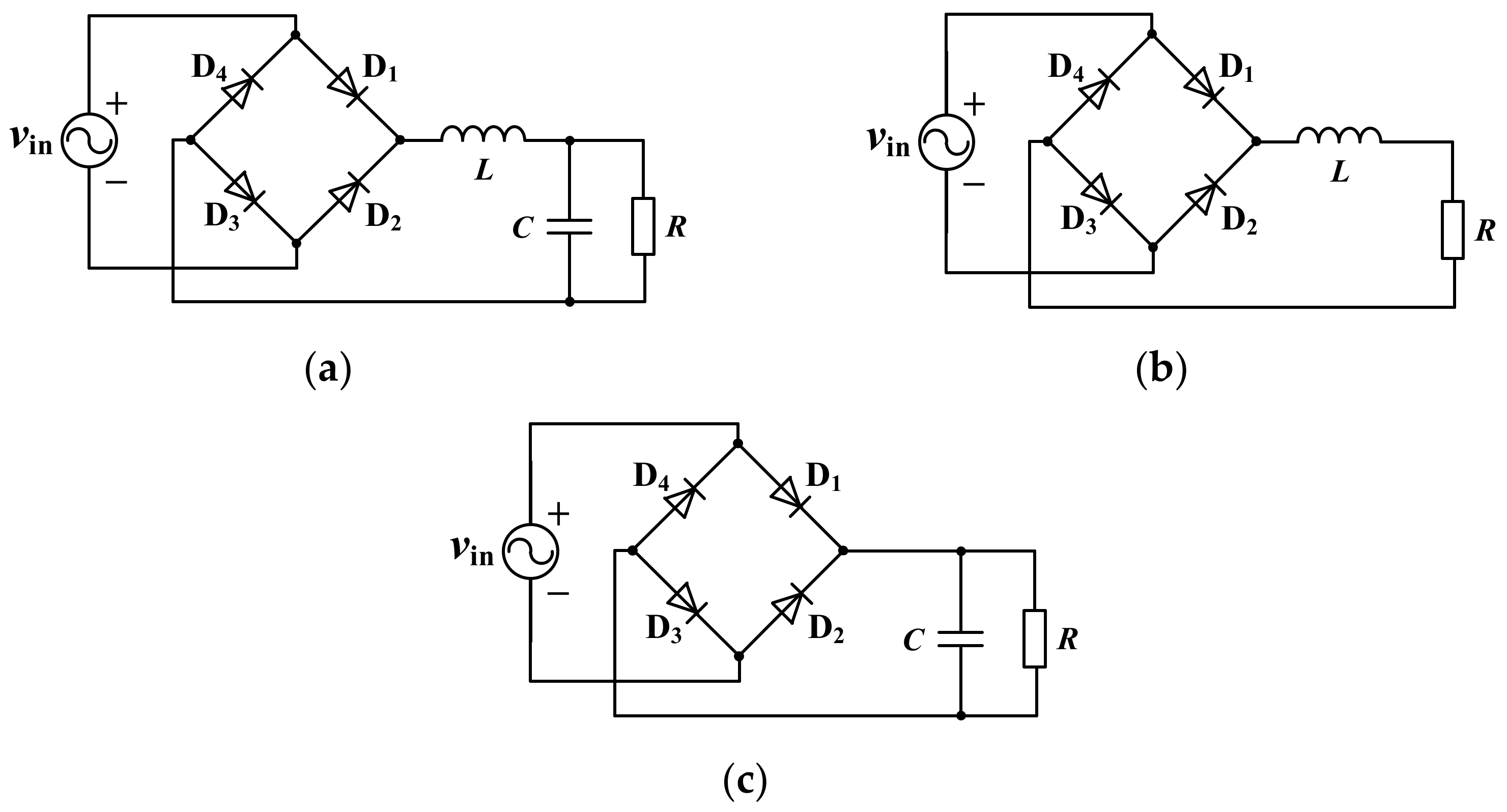
In addition, the external characteristics of some common power electronic circuits also exhibit memristive characteristics [58,59,60]. For example, as shown in Table 5, Corinto and Ascoli demonstrated that the diode rectifier bridge with LCR filtering shown in Figure 8a can exhibit memristive characteristics [58]; H. G. Wu et al. proved that the diode rectifier bridge with LR filtering shown in Figure 8b can exhibit memristive characteristics [59]; B. C. Bao et al. introduced the idea that the diode rectifier bridge with CR filtering shown in Figure 8c can exhibit memristive characteristics [60]. It is foreseen that more and more AC power devices will be found or proved to have memristive characteristics in the future. Therefore, the study of safely supplying power for memristive devices and systems to make them operate stably is positive for the memristor.
2.2.2. Operation Frequency Range of Memristors
With the development of research, more and more memristor emulators have been proposed to study memristive characteristics and their applications. However, most of the reported memristor emulators can only simulate the memristive characteristics at lower frequencies, i.e., below the critical frequency; the memristor emulator shows the “8”-shaped hysteresis loop and degenerates to a linear resistor above the critical frequency [26]. In response to the above situation, researchers have also proposed memristor emulators for different operating frequency ranges.
In 2010, Y. V. Pershin et al. constructed a programmable memristor emulator with a maximum operating frequency of 50 Hz using a digital potentiometer and a microcontroller [61]; in the same year, B. Muthuswamy et al. implemented a cubic nonlinear flux-controlled memristor emulator with an operating frequency limited to less than 500 Hz using operational amplifiers, multipliers, capacitors, and resistors [48]. From 2014 to 2015, M. T. Abuelma’atti et al. implemented a low-input impedance memristor emulator with an operating frequency below 700 Hz and a continuous memristor emulator suitable for a maximum operating frequency of 590 Hz using a current feedback operational amplifier (CFOA), resistors, and capacitors, respectively [62,63]. In 2011, B. C. Bao et al. constructed a segmented quadratic memristor emulator with a maximum operating frequency of about 1 kHz using operational amplifiers, multipliers, resistors, and capacitors [49]; in 2015, W. Liu et al. used the same construction to implement a memristor emulator with a maximum operating frequency of 15 kHz [49]. In the same year, Sánchez-López et al. implemented a memristor emulator with a maximum operating frequency of 160 kHz, described by a multivariate nonlinear function using second-generation current conveyors (CCII), resistors, and capacitors [64]. In 2016, R. P. Wu et al. built a generalized voltage-controlled memristor emulator using a CFOA, multipliers, resistors, and capacitors, etc., and its voltammetric characteristic curve changes to a single-valued function when the excitation frequency is 1.5 kHz [51]. In 2017, A. G. Alharbi et al. [52] used the current backward transconductance amplifier (CBTA), transistors, multipliers, and capacitors to realize an exponential current-controlled memristor emulator with a maximum operating frequency of about 7 kHz [65]; in the same year, U. E. Ayten et al. completed a linear multiparameter memristor emulator with a maximum operating frequency of 10 kHz using the CCII, transistors, resistors, and capacitors [66]. Also in 2017, C. Sánchez-López and L. E. Aguila-Cuapio completed the design of a memristive analog circuit with the highest operating frequency of 860 kHz based on the CCII [67]. In 2020, Y. J. Dong et al. implemented a bistable nonvolatile localized active memristor emulator using operational amplifiers, multipliers, resistors, and capacitors; its voltammetric characteristics exhibit a typical “8”-shaped hysteresis loop when the excitation frequency is less than 3 kHz [52].
With the continuous research, a few memristor emulators whose maximum operating frequency is up to the MHz have also been successfully implemented [68,69,70,71]. In 2014, A. Yesil et al. constructed a memristor emulator with a maximum operating frequency of 1 MHz based on the differential difference current conveyor (DDCC) [68], and in 2018, they designed a linear time-varying memristor emulator with 50 MHz operating frequency based on the MOSFET [69]. In 2019, R. K. Ranjan et al. implemented a floating-ground memristor emulator based on the current conveyor transconductance amplifier (CCTA) and CCII with a maximum operating frequency of 5 MHz [70]. In 2020, N. Raj et al. used an operational transconductance amplifier (OTA), multipliers, resistors, and capacitors to implement a flux-controlled memristor emulator with a maximum operating frequency of 26.3 MHz [71]. In 2021, S. S. Prasad et al. presented a new charge-controlled memristor emulator based on the current follower transconductance amplifier (CFTA), which performs a typical “8”-shaped hysteresis loop at a frequency of up to 9 MHz [72]. Moreover, N. O. Adesina et al. presented the CMOS transistor-based memristor emulator, which can produce the “8”-shaped hysteresis loop in the 15 MHz to 100 MHz range [73]. Additionally, J. Vista and A. Ranjan introduced a flux-controlled memristor emulator realized by employing grounded passive components and a single voltage difference transconductance amplifier (VDTA), which can show the “8”-shaped hysteresis loop up to 50 MHz [74]. Then, Sagar et al. proposed a voltage differencing inverting buffered amplifier (VDIBA)-based resistorless flux-controlled memristor emulator with a maximum operating frequency of 12.7 MHz [75]. Furthermore, S. S. Prasad et al. recommended a single active block-based compact memristor emulator with 12.8 MHz operating frequency [76]. In addition, H. B. Cao et al. [27] came up with a method to extend the ideal memristor band by using a sine function instead of linear term in the ideal memristor model, and the research results show that the improved memristor emulator obtained based on the proposed method can exhibit typical memristive characteristics when the excitation frequency is up to several gigahertz.
From the above abundant achievements, the possibility for the application research of memristors under high frequency conditions has been demonstrated, and the foundation has also been provided for the research of a high-frequency switching converter based on the wide memristor band. However, there are few existing memristor emulators that can exhibit memristive characteristics in the high-excitation-frequency range. So far, few memristor emulators have been reported that can still exhibit the “8”-shaped hysteresis loop in the GHz frequency range. It is necessary to further study the wide-band memristor and its characteristics.
2.2.3. Practical Application of Memristors
The memristor is proposed and implemented to promote the development of circuit design and circuit application. The memristor is a nonlinear element that has natural non-volatile characteristics. The existence of memristors can not only make the integrated circuit element become smaller but also has the ability to simulate the complex human brain nerve function. At present, memristors have been gradually applied in many occasions because of their specific memristive properties, such as high-density non-volatile memory [77,78,79,80], chaotic circuit [81,82,83,84], logic circuit [85,86,87,88], filtering circuit [89,90,91,92], neural network [93,94,95,96], signal processing [97,98,99,100], secure communication [101,102,103,104], etc. In addition, the implementation of the memristor gives a new development goal for the design and research of high-performance power electronic systems [105,106,107].
In addition, memristive electrical equipment needs to work in an AC environment without DC bias, and the inverter circuit is a power electronic conversion circuit that can convert DC into AC and is also a significant power supply for memristive electrical equipment. Therefore, the research on the stable operation of memristive power electronic circuits is an important foundation to promote the development and application of the memristor.
2.3. Deficiency in Research Actuality on the Memristor
Although the current research on the memristor has made some achievements, there are still some shortcomings, mainly reflected in the following two aspects:
(1) The reported memristor emulators can only show the memristive characteristics at a lower excitation frequency and will degrade to the traditional linear resistor at a higher excitation frequency. This limitation seriously affects the application of memristor in high-frequency occasions, such as high-frequency logic circuits, high-frequency oscillation circuits, and so on.
(2) The actual physical memristor is seldom used in the actual experiment because its structure is complex, and its cost is high. At present, the research on memristive characteristics and their application mainly depends on the circuit simulation of a mathematical model memristor or the equivalent realization circuit of the memristor. With the deepening of research, more and more existing AC electrical equipment and systems have been proved to have memristive characteristics, but the mathematical theoretical models used to study these memristive electrical equipment and systems need to be enriched and improved, and the characteristic analysis and application research of memristive electrical equipment and systems are not comprehensive enough.
3. Reviews of Power Electronic Systems and Their Complex Behaviors
3.1. Traditional Inverter and Multilevel Inverter
The DC–AC conversion technology is to transform the DC input voltage of fuel panels and solar panels into AC output voltage when it is added a certain control scheme, which has been broadly applied in industrial applications, for example, uninterruptable power supply, electric vehicle drive, and ultrasonic motor drive [108].
In 1981, Nagaoka University of Science and Technology A. Nabae et al. put forward the three-level inverter circuit structure [109]. Since then, the research on multilevel inverters has developed rapidly. At present, a large number of three-level inverter topologies have been proposed, which can be mainly classified into the diode clamp type (which is also known as NPC three-level inverter circuit or I-type three-level inverter circuit), the flying-span capacitor type and the cascade type [110], as shown in Figure 9a,b. In contrast to the traditional two-level inverter circuit, the three-level inverter circuit possesses obvious advantages such as less output voltage harmonics, less switching loss, high efficiency, and less filter inductance required, so it has been widely used in practical engineering.
Although the diode-midpoint-clamped three-level inverter topology is the most frequently used, it also has some disadvantages such as a large number of devices and uneven distribution of device losses [110]. Therefore, a variety of improved NPC three-level inverters with more advantages have been developed one after another. Among them, the T-type three-level inverter circuit proposed by P. Knaup of Conergy Company in 2007 has attracted the most attention [111]. As shown in Figure 9c, the T-type three-level inverter is a modified topology based on the diode-midpoint-clamped three-level inverter. Compared with diode-midpoint-clamped three-level inverter topology, this topology has fewer devices, less loss, and higher efficiency [112,113], as given in Table 6. The T-type three-level inverter is a promising topology, particularly appropriate for photovoltaic power generation, since the different levels of DC voltage can be expediently formed by the modular structure of photovoltaic arrays, and the T-type three-level inverter can still synthesize low-harmonic distortion-free standard sinusoidal output voltage at lower switching frequencies [114,115]. Therefore, the T-type three-level inverter topology is widely used as the AC power supply for industrial loads in practical engineering and will also be an important power supply for memristive loads.
3.2. Load Types of the Inverter System
As described in [116], the industrial loads in the practical engineering are usually complex nonlinear. At present, the power electronic equipment has also become a common nonlinear load of inverter circuit, and most power electronic appliances are electrical equipment on account of the single-phase diode bridge rectifier circuit, for instance laptops, TVs, compact fluorescent lamps, and so on [117,118]. It is an important task to offer stable AC power supply for this diode-bridge-rectifier-type power electronic equipment. It should be noted that the diode bridge rectifier circuit with inductive load is often used to represent a class of nonlinear load in practice [119,120,121], since the diode bridge rectifier circuit with inductive load can be used to represent not only memristive loads but also power electronic loads. However, the system composed of the nonlinear load and its power supply belongs to the strong nonlinear system, which will undoubtedly produce a variety of nonlinear unstable behaviors, thus seriously affecting the stable operation of the system. Therefore, it is an important topic to study the nonlinear behavior of the inverter system with memristor load to realize the stable operation of the system.
3.3. Research of Complex Dynamic Behavior in Power Electronic Systems
Because of the switching element, the power electronic systems are nonlinear circuits [122], which are likely to produce abundant unstable behaviors [123]. The research on complex behaviors breaking out in power electronic systems started in the 1980s [124,125]. The early research work mainly focused on relatively simple DC–DC conversion circuits [124,125,126,127]. With the deepening of the research, it has been extended to more complex power factor correction (PFC) circuits [128,129,130] and DC–AC circuits [116,131,132,133,134,135,136,137,138,139,140,141]. In 2002, Robert et al. extended the study of nonlinear complex behavior to the field of DC–AC for the first time and analyzed the unstable behaviors in the single-phase H-bridge inverter circuit [131]. Since then, more and more scholars have devoted themselves to the study of complex behavior in inverter circuits and have achieved fruitful results over the years. The analytical methods have also been developed from numerical simulation and experimental analysis to nonlinear dynamics theory. In 2006, T. Kousaka et al. simulated and analyzed the period stability of single-phase H-bridge inverter circuits using the return graph method [132]. In 2008, H. Li et al. proposed an improved discrete-time mapping model and studied the bifurcation phenomenon in voltage-controlled H-bridge inverters [133]. In 2009, X. M. Wang et al. described chaos and bifurcation phenomena in the single-phase sinusoidal pulse width modulation (SPWM) inverter circuits via employing the first-order discrete-time model and using folding graphs as well as bifurcating graphs [134]. In 2011, A. El Aroudi et al. studied Neimark–Sacker bifurcation and period-doubling bifurcation phenomena of the buck-type H-bridge inverter on a switching period scale based on a precise discrete-time model [135]. In 2013, H. C. Liu et al. analyzed the symmetrical bifurcation characteristics of the single-phase H-bridge inverter under peak-valley current control through time-domain waveform diagrams, folding diagrams, and bifurcation diagrams [136]. In the same year, Shankar et al. obtained the monodromy matrix of the full-bridge buck inverter based on the Filippov method and analyzed its intermittent chaotic phenomenon caused by period-doubling bifurcations [137]. In 2020, L. H. Yang et al. used the average model and the improved discrete-time model, respectively, to analyze the mechanism of slow-scale and fast-scale instability behaviors discovered in the parallel single-phase H-bridge inverter system [116]. In the same year, Avrutin et al. came up with a piecewise smooth-mapping modeling method and used it to study the boundary collision bifurcation of the single-phase H-bridge inverter [138]. In 2021, using discrete-time modeling, A. El Aroudi et al. analyzed the sub-harmonic oscillation phenomenon caused by fast-scale bifurcation in the adaptive slope compensation boost inverter [139]. In 2022, H. Y. Ji et al. took the single-phase H-bridge inverter controlled by dual-loop proportional integral with inductive impedance load as the research object and used the state-space average model and the Filippov method to explain the mechanism of slow-scale and fast-scale instability behaviors found in the circuit [140]. Obviously, the results that have been achieved mainly focus on the complex dynamical behaviors of the traditional two-level inverter circuit with linear load, and few consider the multilevel inverters with nonlinear loads and their complex behaviors, nor do they mention the available theoretical methods.
3.4. Classification and Control of Complex Dynamic Behavior
The complex unstable behavior in power electronic systems can be divided into chaos and bifurcation; it should also be noted that bifurcation is one of the ways leading to chaos. Based on different time scales, these instability behaviors can be classified into fast-scale instability and slow-scale instability [141].
As shown in Table 7, among them, the low-frequency dynamical behavior occurring far higher than the switching period is called slow-scale instability. Generally, when there is an outburst in the slow-scale instability, the operation period of the circuit is tens or even thousands of times the switching period [142]. Meanwhile, fast-scale instability refers to the high-frequency dynamical behavior during the switching period. When the fast-scale instability breaks out, the operation period of the circuit changes from one switching period to two switching periods, that is, from period-1 to period-2 [143]. In addition, according to the dynamical mechanism, there are different types of bifurcations, for instance, saddle-junction bifurcation, period-doubling bifurcation, and Hopf bifurcation [144]. It should be noted that, as mentioned in reference [116], the occurrence of bifurcations will increase the harmonic content of the systems, pollute the power supply, and deteriorate the working environment of the loads. That is, the occurrence of bifurcation behaviors in the power electronic systems should be avoided in the actual operation. Therefore, the research on bifurcation control in power electronic circuits can lay a theoretical foundation for ensuring the stable operation of circuits in practical engineering.
The bifurcation control of a given nonlinear circuit and system usually refers to changing its bifurcation characteristics by designing certain control signals, mainly in order to make the given nonlinear circuit and system show some expected dynamical behaviors [145]. Generally, there are some typical objectives on bifurcation control, such as postponing the beginning of the natural bifurcation, introducing a new stable bifurcation solution at a better parameter value, changing the parameter values of the existing bifurcation points, modifying the bifurcation types, and so on [145,146,147,148,149,150,151]. It should be noted that there are some basic differences between the bifurcation control and the classical system control. Since the bifurcation behaviors discovered in one system are related to the characteristic values of its model, the key to realize the bifurcation control of the system is to control these eigenvalues by the appropriate approach [145]. So far, the research on bifurcation control of power electronic systems has involved both DC–DC converters and DC–AC converters. For example, Y. L. Guo et al. achieved effective control of bifurcation behaviors in the buck–boost converter by only introducing inductance current as the control variable so as to change the Jacobian matrix and its eigenvalues [152]. J. K. Wu et al. put forward a kind of general bifurcation control method according to the idea of transfer function and analyzed the influence of the general bifurcation control on the trajectory of the eigenvalues of voltage-type H-bridge inverter circuits, realizing the control of the period-doubling bifurcation and low-frequency oscillation phenomenon in the systems [153]. T. S. Xue et al. take the SPWM H-bridge single-phase inverter in peak current control mode as the object and prove the control effect of the slope compensation method on the bifurcation behavior by analyzing the control influence on the eigenvalues of the Jacobian matrix [154]. Hence the bifurcation control needs to achieve effective control of bifurcation behavior in nonlinear systems with the minimal control cost and the simplest way. At the same time, bifurcation control technology has also been widely used to solve physical and practical engineering problems [155,156,157].
3.5. Modeling Methods for Analyzing Complex Dynamic Behaviors
At present, the important ways to research the instabilities of power electronic systems include time-domain simulation and dynamical theory analysis. It should be noted that the time-domain simulation can be used to describe the characteristic curve of the power electronic system intuitively and can be employed to verify the correctness of the theoretical results. However, the time-domain simulation method has some shortcomings. It cannot explain the dynamical mechanism of unstable behaviors occurring in the power electronic system and cannot offer comprehensive information for the parameter design of the system only via the time-domain simulation. Through appropriate dynamical theories, one can study the dynamical mechanism of the unstable behaviors breaking out in the system, which is an effective way to deeply understand the unstable behavior of the system. When analyzing the dynamical behaviors of the power electronic system, the modeling of nonlinear switches and the processing of discrete characteristics in the system are the main problems that need to be solved. In this regard, different modeling methods have been proposed to solve the above problems, among which, the harmonic-state-space modeling method [158,159,160], discrete-time modeling method [116], and average modeling method [138] have been widely used in the dynamical behavior analysis of power electronic systems.
As shown in Table 8, among them, the average state modeling method can describe the dynamical characteristics of the power electronic systems well. Note that, because of averaging, neither capacitance voltage nor inductive current fluctuations on account of switching state transitions can be detected in the averaging model in one switching cycle. Therefore, the low-frequency dynamical behaviors of the power electronic systems are often analyzed by the average model, while the high-frequency dynamical information of the system can be described by the discrete-time modeling and the harmonic-state-space modeling. When the power electronic systems require considering harmonic coupling, the harmonic-state-space model can be used to analyze their dynamical characteristics. Note that the accuracy of the model is determined by the harmonic order of the harmonic-state-space model. The harmonic-state-space model becomes more accurate as the harmonic order increases; however, a higher-precision model is going to make the calculation process complicated [146]. In addition, when the harmonic-state-space modeling is used to analyze the power electronic system, it is usually completed by frequency-domain convolution calculation, which will make two different frequency components generate new coupled components so that the calculation becomes more complicated. Therefore, it obviously carries more redundant information when the harmonic-state-space model is used to explore the mechanism of the unstable behavior of the power electronic systems [160]. Nevertheless, the discrete-time modeling can describe the high-frequency dynamical information of the system accurately and intuitively, so it has become an important method for the modeling of the power electronic systems [133,134]. The universal discrete-time stroboscopic mapping modeling is given in [123], but this modeling method is only applicable to the simplified system whose state equation has a reversible coefficient matrix. For example, in [134], the dynamical mechanism of the fast-scale instability in the H-bridge inverter system with linear resistance load under proportional control is explored via the universal discrete-time stroboscopic mapping model. Aiming at this deficiency, an improved discrete-time modeling method is presented in [133], and the dynamical mechanism of the fast-scale instability in the parallel H-bridge inverter with linear resistance load under PI control is explored via this improved discrete-time model. Note that this analysis method is only applicable to the system whose state equation has a time-invariant coefficient matrix. However, in practical engineering, the coefficient matrix in the equation state of some systems is irreversible and periodic time-varying, such as the multilevel inverter system with memristive load, will make the analysis method described above unable to be applied. Therefore, for the power electronic systems with irreversible and periodic time-varying coefficient matrix of the state equations, it is necessary to propose a more suitable analysis method for analyzing their mechanism of the instability.
3.6. The Deficiency of Complex Behavior Research in Power Electronic Systems
Obviously, according to the above analysis, previous research on unstable behavior in power electronic systems mainly focused on the traditional two-level inverter systems with linear load. In fact, industrial loads are usually complex nonlinear loads. At the same time, with the increasing requirements of the power capacity and efficiency of AC power supply, in comparison to the traditional two-level inverter, the three-level inverter, because of its advantages of less output voltage harmonics, high efficiency, and easy control, has been widely used in practical engineering and is usually used as the power supply for actual nonlinear loads. It is certain that, since the concurrent impact of switching and nonlinear load, the multilevel inverter with memristive load, which is a strong nonlinear system, is easy to produce rich and complex nonlinear behaviors under certain system parameters. Note that these complex nonlinear behaviors lead to a large amount of noise so as to affect the stable operation of the system, which should be avoided in actual operation. However, there is little research on the complex dynamical behaviors and their control in the multilevel inverter with memristive load at present, and the relevant theories for the analyses of the dynamical mechanism of the unstable behavior breaking out in power electronic systems with periodic time-varying characteristics are not specific.
3.7. Complex Behaviors in the Power Converters with Memristive Loads
The previous studies have shown that memristive loads have a certain influence on the dynamical characteristics of the power electronic circuits [105,106,107]. In [105], the peak current mode (PCM) buck–boost converter with a voltage-controlled memristive load was built; its complex dynamic behaviors were analyzed by MATLAB simulation, and the dynamical impact of the voltage-controlled memristive load on the buck–boost converter was revealed. Among them, the influence of the memristive load on the characteristics of the power electronic circuit is explored, which suggested that the PCM memristive buck–boost converter displays complicated dynamical behaviors, such as boundary collision bifurcation, periodic bifurcation, period-doubling bifurcation, and chaos. In [106], the complicated dynamical behaviors discovered in a PCM-controlled boost converter with memristive load is explored, where its bifurcation and chaotic behaviors are investigated by means of MATLAB simulation and PSIM software; additionally, they are suppressed by using time-delay feedback control. In [107], the periodic bifurcation and chaotic behaviors of the switched-inductor buck–boost (SIBB) converter with memristive load are found. The bifurcation diagram and phase diagram are drawn using MATLAB simulation, then a chaotic suppression method is presented to make the SIBB memristive converter operate stably.
With the deepening of the research, the research object also developed from DC–DC converters to DC–AC converters and other complex power electronic circuits, and the analysis means also developed from simple numerical simulation to nonlinear dynamics theory. The inverter circuit is a power electronic conversion circuit that can convert DC into AC; it is also the power supply for memristive electrical equipment. In [133], the voltage-controlled traditional full-bridge inverter whose load is the memristor is built, and the analysis result shows that Hopf bifurcation leads to the occurrence of medium-frequency oscillation in the system. Recently, the slow-scale and fast-scale instabilities in the three-level inverter with memristive load are analyzed, respectively, in [142,143]. In [142], the average model of the three-level single-phase inverter with memristive load is constructed, and then its essential mechanism of slow-scale instability is revealed by combining Floquet theory and the harmonic balance method. In [143], the discrete-time mapping model of the three-level single-phase inverter with memristive load is built, and its dynamical mechanism of the fast-scale instability is explored based on Floquet theory and the Filippov method.
The above research shows that the power electronic system with memristive load is the strong nonlinear system, so that the memristive power electronic systems is likely to result in abundant unstable behaviors, which will lead to the instability of memristive power electronic systems. Consequently, it is significant to further explore the unstable behavior of power electronic system with memristive load, and it is an important foundation to promote the development and application of the memristor.
4. The Importance and Necessity of Complex Behaviors in Power Electronic Systems
The operating frequency range of memristor seriously affects its practical application [29]. However, a mass of existing memristor emulators can only simulate the memristive behavior at a low operating frequency. That is, under the critical frequency, the memristor emulators show the typical memristive characteristics, while beyond the critical frequency, the memristor emulators will regress into a single-valued function. No doubt that this limitation seriously affects the practical application and characteristic research of the existing memristor emulators. Therefore, it is of great significance to propose effective methods to make the memristor meet the increasing requirements in practical applications. Because the physical model memristor has the disadvantages of complex structure, high production cost, and a difficult mathematical model, the current experimental research on the characteristics of the memristor is mainly based on relatively simple mathematical model memristors. Note that more and more existing AC electrical devices have been proved to have the memristive characteristic. However, these AC electrical devices cannot be described by the basic ideal memristor model and need to be analyzed based on the generalized memristor model. Hence, it is necessary to continue to enrich and improve the generalized memristor model so as to carry out in-depth research on the characteristics and the practical application of the memristor.
The inverter is an important power supply for memristive loads because it can supply AC power for the memristive equipment. However, the power electronic system with memristive load is generally a strong nonlinear system. The results show that the strong nonlinear systems have rich and complex dynamic behaviors during their operation. These instability phenomena will increase the current stress of switching components, increase the harmonic content of the system, lead to the deterioration of the operating environment for the memristive loads, and affect the normal operation of other components and equipment of the systems. Therefore, it is significative to study the complex behavior and its control of the power electronic systems with memristive load for improving their overall performance. Moreover, the research results can offer a basis for the parameter design and optimization of the power electronic system with memristive load. In addition, the study of the essential mechanism of the instability phenomenon in strongly nonlinear power electronic systems can not only provide reference for improving the system design but also provide beneficial supplement for the dynamical theories. Meanwhile, it is of great significance to promote the wide application of multilevel inverter in memristive electrical equipment.
As can be seen from the above, the future work can be started from the following aspects:
(1) The multi-level inverter systems with memristive loads are strongly nonlinear, which are likely to complicate dynamical behaviors. The possible unstable phenomena occurring in the systems and their dynamic mechanism can be explored, and the effective control methods of instability phenomena can be studied.
(2) In practical engineering, digital control has been widely used in the control of the power electronic system because of its simple control and strong anti-interference ability. However, digital control also has the shortcomings of delay and discontinuity; hence, the influence of the digital control delay on the bifurcation behavior in the power electronic systems with memristive loads can be studied.
(3) The AC power supply usually adopts the form of a parallel inverter system to meet the increasing demand for its power capacity and reliability in practical engineering. However, the small difference of the output voltage between the inverters of the parallel system may lead to the unstable behaviors of the system; valid control methods should also be chosen to ensure reasonable cooperation between the modules. Factually, the parallel inverter system has strong coupling and nonlinear characteristics, and the whole system is more complex. Therefore, the stabilities of the parallel inverter systems with memristive loads can be studied.
(4) The three-phase multilevel inverter system in cascaded or parallel mode has a more complex topology structure, which makes it difficult to obtain the average model and discrete-time model. Therefore, one can take the three-phase multilevel cascaded or parallel memristive inverter system as the object to study the theoretical analysis method of its complex dynamics.
5. Conclusions
With the deepening of the research, more and more electrical devices and systems have been proved to exhibit the typical memristive characteristic under AC excitation; studying the power electronic systems with memristive loads and making them operation stably will also play a positive role in promoting the development of the memristor and the power electronic system. However, the available research results show that the power electronic systems composed of memristive devices and power supplies are of strong nonlinearity. Therefore, exploring complicated unstable behaviors in power electronic systems with strong nonlinearity is essential. Accordingly, in this paper, the research status on complex behaviors of power electronic systems with memristive loads is summarized, the development status of the memristor is analyzed comprehensively, the significance of the memristor for the power electronic systems is expounded, and the research progress of dynamical behaviors in the power electronic systems with memristive loads is described, so as to provide guidance for studying the complex behavior of strongly nonlinear systems.
Author Contributions
H.C. set up the framework of this paper and wrote the paper. F.W. took part in developing the research proposal and revising the paper. All authors have read and agreed to the published version of the manuscript.
Funding
This research received no external funding.
Conflicts of Interest
The authors declare no conflict of interest.
References
- Chua, L.O. Memristor-the missing circuit element. IEEE Trans. Circuit Theory 1971, 18, 507–519. [Google Scholar] [CrossRef]
- Strukov, D.B.; Snider, G.S.; Stewart, D.R.; Williams, R.S. The missing memristor found. Nature 2008, 453, 80–83. [Google Scholar] [CrossRef] [PubMed]
- Sahin, M.E.; Taskiran, Z.G.C.; Guler, H.; Hamamci, S.E. Simulation and implementation of memristive chaotic system and its application for communication systems. Sens. Actuators A Phys. 2019, 290, 107–118. [Google Scholar] [CrossRef]
- Isah, A.; Nguetcho, A.S.T.; Binczak, S.; Bilbault, J.M. Memristor dynamics involved in cells communication for a 2D non-linear network. IET Signal Process. 2020, 14, 427–434. [Google Scholar] [CrossRef]
- Xiu, C.B.; Zhou, R.X.; Liu, Y.X. New chaotic memristive cellular neural network and its application in secure communication system. Chaos Solitons Fractals 2020, 141, 110316. [Google Scholar] [CrossRef]
- Ji, X.Y.; Dong, Z.K.; Lai, C.S.; Qi, D.L. A brain-inspired in-memory computing system for neuronal communication via memristive circuits. IEEE Commun. Mag. 2022, 60, 100–106. [Google Scholar] [CrossRef]
- Lee, T.H.; Hwang, H.G.; Woo, J.U.; Kim, D.H.; Kim, T.W.; Nahm, S. Synaptic plasticity and metaplasticity of biological synapse realized in a KNbO3 memristor for application to artificial synapse. ACS Appl. Mater. Interfaces 2018, 10, 25673–25682. [Google Scholar] [CrossRef] [PubMed]
- Zhang, C.; Ye, W.B.; Zhou, K.; Chen, H.Y.; Yang, J.Q.; Ding, G.L.; Chen, X.L.; Zhou, Y.; Zhou, L.; Li, F.J.; et al. Bioinspired artificial sensory nerve based on nafion memristor. Adv. Funct. Mater. 2019, 29, 1808783. [Google Scholar] [CrossRef]
- Wu, L.D.; Wang, Z.W.; Wang, B.W.; Chen, Q.Y.; Bao, L.; Yu, Z.Z.; Yang, Y.F.; Ling, Y.T.; Qin, Y.B.; Tang, K.C.; et al. Emulation of biphasic plasticity in retinal electrical synapses for light-adaptive pattern pre-processing. Nanoscale 2021, 13, 3483–3492. [Google Scholar] [CrossRef]
- Dai, Y.H.; Wang, X.Q.; Yang, B. An improved memristor model based on the electrochemical metallization effect as a synapse for biomimetic applications. Phys. Status Solidi B Basic Solid State Phys. 2021, 259, 2100379. [Google Scholar] [CrossRef]
- Liu, S.J.; Wang, Y.Z.; Fardad, M.; Varshney, P.K. A memristor-based optimization framework for artificial intelligence applications. IEEE Circuits Syst. Mag. 2018, 18, 29–44. [Google Scholar] [CrossRef]
- Hajto, D.; Rak, A.; Cserey, G. Robust memristor networks for neuromorphic computation applications. Materials 2019, 12, 3573. [Google Scholar] [CrossRef] [PubMed] [Green Version]
- Miranda, E.; Sune, J. Memristors for neuromorphic circuits and artificial intelligence applications. Materials 2020, 13, 938. [Google Scholar] [CrossRef] [PubMed] [Green Version]
- Pei, Y.F.; Li, Z.Q.; Li, B.; Zhao, Y.; He, H.; Yan, L.; Li, X.Y.; Wang, J.J.; Zhao, Z.; Sun, Y.; et al. A multifunctional and efficient artificial visual perception nervous system with Sb2Se3/CdS-core/shell (SC) nanorod arrays optoelectronic memristor. Adv. Funct. Mater. 2022, 32, 2203454. [Google Scholar] [CrossRef]
- Duan, S.K.; Hu, X.F.; Wang, L.D.; Li, C.D.; Mazumder, P. Memristor-based RRAM with applications. Sci. China Inf. Sci. 2012, 55, 1446–1460. [Google Scholar] [CrossRef]
- Kim, K.H.; Gaba, S.; Wheeler, D.; Cruz-Albrecht, J.M.; Hussain, T.; Srinivasa, N.; Lu, W. A functional hybrid memristor crossbar-array/CMOS system for data storage and neuromorphic applications. Nano Lett. 2012, 12, 389–395. [Google Scholar] [CrossRef] [PubMed]
- Chen, Y.; Liu, G.; Wang, C.; Zhang, W.B.; Li, R.W.; Wang, L.X. Polymer memristor for information storage and neuromorphic applications. Mater. Horiz. 2014, 1, 489–506. [Google Scholar] [CrossRef]
- Qian, W.H.; Cheng, X.F.; Zhou, J.; He, J.H.; Li, H.; Xu, Q.F.; Li, N.J.; Chen, D.Y.; Yao, Z.G.; Lu, J.M. Lead-free perovskite MASnBr3-based memristor for quaternary information storage. InfoMat 2020, 2, 743–751. [Google Scholar] [CrossRef] [Green Version]
- Priyanka, M.M.; Ravi, T. Survey on role of memristor in electronics. In Proceedings of the 2015 IEEE International Conference on Control, Instrumentation, Communication and Computational Technologies (ICCICCT), Thuckalay, India, 18–19 December 2015; pp. 722–726. [Google Scholar]
- Chen, Q.Y.; Lin, M.; Wang, Z.W.; Zhao, X.L.; Cai, Y.M.; Liu, Q.; Fang, Y.C.; Yang, Y.C.; He, M.; Huang, R. Low power parylene-based memristors with a graphene barrier layer for flexible electronics applications. Adv. Electron. Mater. 2019, 5, 1800852. [Google Scholar] [CrossRef]
- Yang, Y.; Du, H.Y.; Xue, Q.; Wei, X.H.; Yang, Z.B.; Xu, C.G.; Lin, D.M.; Jie, W.J.; Hao, J.H. Three-terminal memtransistors based on two-dimensional layered gallium selenide nanosheets for potential low-power electronics applications. Nano Energy 2019, 57, 566–573. [Google Scholar] [CrossRef]
- Yang, J.; Lee, H.; Jeong, J.H.; Kim, T.; Lee, S.H.; Song, T. Circuit-level exploration of ternary logic using memristors and MOSFETs. IEEE Trans. Circuits Syst. I Regul. Pap. 2022, 69, 707–720. [Google Scholar] [CrossRef]
- Chua, L.O. The fourth element. Proc. IEEE 2012, 100, 1920–1927. [Google Scholar] [CrossRef]
- Chua, L.O. If it’s pinched it’s a memristor. Semicond. Sci. Technol. 2014, 29, 104001. [Google Scholar] [CrossRef]
- Chua, L.O.; Kang, S.M. Memristive devices and systems. Proc. IEEE 1976, 64, 209–223. [Google Scholar] [CrossRef]
- Adhikari, S.P.; Sah, M.P.; Kim, H.; Chua, L.O. Three fingerprints of memristor. IEEE Trans. Circuits Syst. I Regul. Pap. 2013, 60, 3008–3021. [Google Scholar] [CrossRef]
- Wang, X.B.; Chen, Y.R.; Xi, H.W.; Li, H.; Dimitrov, D. Spintronic memristor through spin-torque-induced magnetization motion. IEEE Electron Device Lett. 2009, 30, 294–297. [Google Scholar] [CrossRef]
- Mostafa, H.; Ismail, Y. Process variation aware design of multi-valued spintronic memristor-based memory arrays. IEEE Trans. Semicond. Manuf. 2016, 29, 145–152. [Google Scholar] [CrossRef]
- Huang, W.C.; Fang, Y.W.; Yin, Y.W.; Tian, B.B.; Zhao, W.B.; Hou, C.M.; Ma, C.; Li, Q.; Tsymbal, E.Y.; Duan, C.G.; et al. Solid-state synapse based on magnetoelectrically coupled memristor. ACS Appl. Mater. Interfaces 2018, 10, 5649–5656. [Google Scholar] [CrossRef]
- Nafea, S.F.; Dessouki, A.A.S.; El-Rabaie, S.; Elnaghi, B.E.; Ismail, Y.; Mostafa, H. An accurate model of domain-wall-based spintronic memristor. Integration 2019, 65, 149–162. [Google Scholar] [CrossRef]
- Zakhidov, A.A.; Jung, B.; Slinker, J.D.; Abruna, H.D.; Malliaras, G.G. A light-emitting memristor. Org. Electron. 2010, 11, 150–153. [Google Scholar] [CrossRef]
- Maier, P.; Hartmann, F.; Dias, M.R.S.; Emmerling, M.; Schneider, C.; Castelano, L.K.; Kamp, M.; Marques, G.E.; Lopez-Richard, V.; Worschech, L.; et al. Light sensitive memristor with bi-directional and wavelength-dependent conductance control. Appl. Phys. Lett. 2016, 109, 023501. [Google Scholar] [CrossRef] [Green Version]
- Zhu, Y.B.; Wu, C.X.; Xu, Z.W.; Liu, Y.; Hu, H.L.; Guo, T.L.; Kim, T.W.; Chai, Y.; Li, F.S. Light-emitting memristors for optoelectronic artificial efferent nerve. Nano Lett. 2021, 21, 6087–6094. [Google Scholar] [CrossRef] [PubMed]
- Wang, Z.H.; Zhao, W.S.; Kang, W.; Zhang, Y.; Klein, J.O.; Ravelosona, D.; Zhang, Y.G.; Chappert, C. Nonvolatile boolean logic block based on ferroelectric tunnel memristor. IEEE Trans. Magn. 2014, 50, 9100604. [Google Scholar] [CrossRef]
- Wang, Z.H.; Zhao, W.S.; Kang, W.; Zhang, Y.; Klein, J.O.; Ravelosona, D.; Chappert, C. Compact modelling of ferroelectric tunnel memristor and its use for neuromorphic simulation. Appl. Phys. Lett. 2014, 104, 053505. [Google Scholar] [CrossRef]
- Mikheev, V.; Chouprik, A.; Lebedinskii, Y.; Zarubin, S.; Matveyev, Y.; Kondratyuk, E.; Kozodaev, M.G.; Markeev, A.M.; Zenkevich, A.; Negrov, D. Ferroelectric second-order memristor. ACS Appl. Mater. Interfaces 2019, 11, 32108–32114. [Google Scholar] [CrossRef] [PubMed]
- McConville, J.P.V.; Lu, H.D.; Wang, B.; Tan, Y.Z.; Cochard, C.; Conroy, M.; Moore, K.; Harvey, A.; Bangert, U.; Chen, L.Q.; et al. Ferroelectric domain wall memristor. Adv. Funct. Mater. 2020, 30, 2000109. [Google Scholar] [CrossRef]
- Samardzic, N.; Bajac, B.; Srdic, V.V.; Stojanovic, G.M. Conduction mechanisms in multiferroic multilayer BaTiO3/NiFe2O4/BaTiO3 memristors. J. Electron. Mater. 2017, 46, 5492–5496. [Google Scholar] [CrossRef]
- Samardzic, N.M.; Bajac, B.; Bajic, J.; Durdic, E.; Miljevic, B.; Srdic, V.V.; Stojanovic, G.M. Photoresistive switching of multiferroic thin film memristors. Microelectron. Eng. 2018, 187, 139–143. [Google Scholar] [CrossRef]
- Sun, B.; Zhou, G.D.; Sun, L.F.; Zhao, H.B.; Chen, Y.Z.; Yang, F.; Zhao, Y.; Song, Q.L. ABO3 multiferroic perovskite materials for memristive memory and neuromorphic computing. Nanoscale Horiz. 2021, 6, 939–970. [Google Scholar] [CrossRef]
- Torrezan, A.C.; Strachan, J.P.; Medeiros-Ribeiro, G.; Williams, R.S. Sub-nanosecond switching of a tantalum oxide memristor. Nanotechnology 2011, 22, 485203. [Google Scholar] [CrossRef]
- Leon, J.J.D.; Norris, K.J.; Yang, J.J.; Sevic, J.F.; Kobayashi, N.P. A niobium oxide-tantalum oxide selector-memristor self-aligned nanostack. Appl. Phys. Lett. 2017, 110, 103102. [Google Scholar]
- Mladenov, V.; Kirilov, S. A simplified tantalum oxide memristor model, parameters estimation and application in memory crossbars. Technologies 2022, 10, 6. [Google Scholar] [CrossRef]
- Kim, S.; Kim, H.; Hwang, S.; Kim, M.H.; Chang, Y.F.; Park, B.G. Analog synaptic behavior of a silicon nitride memristor. ACS Appl. Mater. Interfaces 2017, 9, 40420–40427. [Google Scholar] [CrossRef]
- Gismatulin, A.A.; Gritsenko, V.A.; Yen, T.J.; Chin, A. Charge transport mechanism in SiNx-based memristor. Appl. Phys. Lett. 2019, 115, 253502. [Google Scholar] [CrossRef]
- Gismatulin, A.A.; Kamaev, G.N.; Kruchinin, V.N.; Gritsenko, V.A.; Orlov, O.M.; Chin, A. Charge transport mechanism in the forming-free memristor based on silicon nitride. Sci. Rep. 2021, 11, 2417. [Google Scholar] [CrossRef] [PubMed]
- Kochergin, V.S.; Yakimov, A.V.; Klyuev, A.V.; Filatov, D.O.; Gorshkov, O.N.; Antonov, D.A.; Mikhaylov, A.N.; Sunyaikin, D.V.; Shtraub, N.I.; Vasileiadis, N.; et al. Effect of SiO2 sublayer on the retention characteristics of nanometer-sized Si3N4 memristive devices investigated by low-frequency noise spectroscopy. Jpn. J. Appl. Phys. 2022, 61, SM1013. [Google Scholar] [CrossRef]
- Muthuswamy, B. Implementing memristor based chaotic circuits. Int. J. Bifurc. Chaos 2010, 20, 1335–1350. [Google Scholar] [CrossRef]
- Bao, B.C.; Xu, J.P.; Zhou, G.H.; Ma, Z.H.; Zou, L. Chaotic memristive circuit: Equivalent circuit realization and dynamical analysis. Chin. Phys. B 2011, 20, 120502. [Google Scholar] [CrossRef]
- Liu, W.; Wang, F.Q.; Ma, X.K. A unified cubic flux-controlled memristor: Theoretical analysis, simulation and circuit experiment. Int. J. Numer. Model. Electron. Netw. Devices Fields 2015, 28, 335–345. [Google Scholar] [CrossRef]
- Wu, R.P.; Wang, C.H. A new simple chaotic circuit based on memristor. Int. J. Bifurc. Chaos 2016, 26, 1650145. [Google Scholar] [CrossRef]
- Dong, Y.J.; Wang, G.Y.; Chen, G.R.; Shen, Y.R.; Ying, J.J. A bistable nonvolatile locally-active memristor and its complex dynamics. Commun. Nonlinear Sci. Numer. Simul. 2020, 84, 105203. [Google Scholar] [CrossRef]
- Lin, D.; Chua, L.O.; Hui, S.Y. The first man-made memristor: Circa 1801 [Scanning Our Past]. Proc. IEEE 2015, 103, 131–136. [Google Scholar] [CrossRef]
- Gandhi, G.; Aggarwal, V.; Chua, L.O. The detectors used in the first radios were memristors. In Memristor Networks; Springer International Publishing: Berlin/Heidelberg, Germany, 2014; pp. 53–66. [Google Scholar]
- Prodromakis, T.; Toumazou, C.; Chua, L.O. Two centuries of memristors. Nat. Mater. 2012, 11, 478–481. [Google Scholar] [CrossRef] [PubMed]
- Gandhi, G.; Aggarwal, V.; Chua, L.O. The first radios were made using memristors. IEEE Circuits Syst. Mag. 2013, 13, 8–16. [Google Scholar] [CrossRef]
- Lin, D.Y.; Hui, S.Y.R.; Chua, L.O. Gas discharge lamps are volatile memristors. IEEE Trans. Circuits Syst. I Regul. Pap. 2014, 61, 2066–2073. [Google Scholar] [CrossRef] [Green Version]
- Corinto, F.; Ascoli, A. Memristive diode bridge with LCR filter. Electron. Lett. 2012, 48, 824–825. [Google Scholar] [CrossRef]
- Wu, H.G.; Bao, B.C.; Xu, Q. First order generalized memrsitor emulator based on diode bridge and series RL filter. Acta Electron. Sin. 2015, 43, 2129–2132. [Google Scholar]
- Bao, B.C.; Xu, L.; Wu, Z.M.; Chen, M.; Wu, H.G. Coexistence of multiple bifurcation modes in memristive diode-bridge based canonical Chua’s circuit. Int. J. Electron. 2018, 105, 1159–1169. [Google Scholar] [CrossRef]
- Pershin, Y.V.; Di Ventra, M. Practical approach to programmable analog circuits with memristors. IEEE Trans. Circuits Syst. I Regul. Pap. 2010, 57, 1857–1864. [Google Scholar] [CrossRef] [Green Version]
- Abuelma’atti, M.T.; Khalifa, Z.J. A new memristor emulator and its application in digital modulation. Analog. Integr. Circuits Signal Process. 2014, 80, 577–584. [Google Scholar] [CrossRef]
- Abuelma’atti, M.T.; Khalifa, Z.J. A continuous-level memristor emulator and its application in a multivibrator circuit. AEU-Int. J. Electron. Commun. 2015, 69, 771–775. [Google Scholar] [CrossRef]
- Sánchez-López, C.; Carrasco-Aguilar, M.A.; Muñiz-Montero, C. A 16Hz–160kHz memristor emulator circuit. AEU-Int. J. Electron. Commun. 2015, 69, 1208–1219. [Google Scholar] [CrossRef]
- Alharbi, A.G.; Fouda, M.E.; Khalifa, Z.J.; Chowdhury, M.H. Electrical nonlinearity emulation technique for current-controlled memristive devices. IEEE Access 2017, 5, 5399–5409. [Google Scholar] [CrossRef]
- Ayten, U.E.; Minaei, S.; Sagbas, M. Memristor emulator circuits using single CBTA. AEU-Int. J. Electron. Commun. 2017, 82, 109–118. [Google Scholar] [CrossRef]
- Sanchez-Lopez, C.; Aguila-Cuapio, L.E. A 860 kHz grounded memristor emulator circuit. AEU-Int. J. Electron. Commun. 2017, 73, 23–33. [Google Scholar] [CrossRef]
- Yesil, A.; Babacan, Y.; Kacar, F. A new DDCC based memristor emulator circuit and its applications. Microelectron. J. 2014, 45, 282–287. [Google Scholar] [CrossRef]
- Yesil, A. A new grounded memristor emulator based on MOSFET-C. AEU-Int. J. Electron. Commun. 2018, 91, 143–149. [Google Scholar] [CrossRef]
- Ranjan, R.K.; Sagar, S.; Roushan, S.; Kumari, B.; Rani, N.; Khateb, F. High-frequency floating memristor emulator and its experimental results. IET Circuits Devices Syst. 2019, 13, 292–302. [Google Scholar] [CrossRef]
- Raj, N.; Ranjan, R.K.; Khateb, F. Flux-controlled memristor emulator and its experimental results. IEEE Trans. Very Large Scale Integr. (VLSI) Syst. 2020, 28, 1050–1061. [Google Scholar] [CrossRef]
- Prasad, S.S.; Kumar, P.; Ranjan, R.K. Resistorless memristor emulator using CFTA and its experimental verification. IEEE Access 2021, 9, 64065–64075. [Google Scholar] [CrossRef]
- Adesina, N.O.; Khan, M.A.U.; Jian, X. CMOS transistor-based memristor emulator circuit design for high frequency applications. In Proceedings of the 2021 IEEE 12th Annual Information Technology, Electronics and Mobile Communication Conference (IEMCON), Vancouver, BC, Canada, 27–30 October 2021. [Google Scholar]
- Vista, J.; Ranjan, A. Flux controlled floating memristor employing VDTA: Incremental or decremental operation. IEEE Trans. Comput.-Aided Des. Integr. Circuits Syst. 2021, 40, 364–372. [Google Scholar] [CrossRef]
- Sagar; Raj, N.; Verma, V.K. Electronically tunable flux-controlled resistorless memristor emulator. IEEE Can. J. Electr. Comput. Eng. 2022, 45, 311–317. [Google Scholar] [CrossRef]
- Prasad, S.S.; Kumar, P.; Raj, N. A compact floating and grounded memristor model using single active element. AEU-Int. J. Electron. Commun. 2022, 157, 154426. [Google Scholar] [CrossRef]
- Guan, W.H.; Long, S.B.; Liu, Q.; Liu, M.; Wang, W. Nonpolar nonvolatile resistive switching in Cu doped ZrO2. IEEE Electron Device Lett. 2008, 29, 434–437. [Google Scholar] [CrossRef]
- Faruque, K.A.; Biswas, B.R.; Rashid, A.B.M.H.U. Memristor-based low-power high-speed nonvolatile hybrid memory array design. Circuits Syst. Signal Process. 2017, 36, 3585–3597. [Google Scholar] [CrossRef]
- Wong, C.W.I.; Ho, P.W.C. Multilevel memristive non-volatile look-up table using two transmission gates one memristor memory cells. Semicond. Sci. Technol. 2020, 35, 105019. [Google Scholar]
- Wu, L.; Liu, H.X.; Lin, J.F.; Wang, S.L. Volatile and nonvolatile memory operations implemented in a Pt/HfO/Ti memristor. IEEE Trans. Electron Devices 2021, 68, 1622–1626. [Google Scholar] [CrossRef]
- Bao, B.C.; Xu, J.P.; Liu, Z. Initial state dependent dynamical behaviors in a memristor based chaotic circuit. Chin. Phys. Lett. 2010, 27, 070504. [Google Scholar]
- Guo, M.; Xue, Y.B.; Gao, Z.H.; Zhang, Y.M.; Dou, G. Dynamic analysis of a physical SBT memristor-based chaotic circuit. Int. J. Bifurc. Chaos 2018, 27, 1730047. [Google Scholar] [CrossRef]
- Sun, J.W.; Zhao, X.T.; Fang, J.; Wang, Y.F. Autonomous memristor chaotic systems of infinite chaotic attractors and circuitry realization. Nonlinear Dyn. 2018, 94, 2879–2887. [Google Scholar] [CrossRef]
- Lai, Q.; Wan, Z.Q.; Kengne, L.K.; Kuate, P.D.K.; Chen, C.Y. Two-memristor-based chaotic system with infinite coexisting attractors. IEEE Trans. Circuits Syst. II Express Briefs 2021, 68, 2197–2201. [Google Scholar] [CrossRef]
- Papandroulidakis, G.; Vourkas, I.; Vasileiadis, N.; Sirakoulis, G.C. Boolean logic operations and computing circuits based on memristors. IEEE Trans. Circuits Syst. II Express Briefs 2014, 61, 972–976. [Google Scholar] [CrossRef]
- Wang, H.P.; Lin, C.C.; Wu, C.C.; Chen, Y.C.; Wang, C.Y. On synthesizing memristor-based logic circuits with minimal operational pulses. IEEE Trans. Very Large Scale Integr. (VLSI) Syst. 2018, 26, 2842–2852. [Google Scholar] [CrossRef]
- Luo, L.; Dong, Z.K.; Duan, S.K.; Lai, C.S. Memristor-based stateful logic gates for multi-functional logic circuit. IET Circuits Devices Syst. 2020, 14, 811–818. [Google Scholar] [CrossRef]
- Liu, G.Z.; Shen, S.H.; Jin, P.P.; Wang, G.Y.; Liang, Y. Design of memristor-based combinational logic circuits. Circuits Syst. Signal Process. 2021, 40, 5825–5846. [Google Scholar] [CrossRef]
- Sozen, H.; Cam, U. First-order memristor-capacitor filter circuits employing HP memristor. J. Circuits Syst. Comput. 2014, 23, 1450116. [Google Scholar] [CrossRef]
- Bao, B.C.; Wu, P.Y.; Bao, H.; Chen, M.; Xu, Q. Chaotic bursting in memristive diode bridge-coupled Sallen-Key lowpass filter. Electron. Lett. 2017, 53, 1104–1105. [Google Scholar] [CrossRef]
- Yu, Y.B.; Yang, N.J.; Yang, C.Y.; Nyima, T. Memristor bridge-based low pass filter for image processing. J. Syst. Eng. Electron. 2019, 30, 448–455. [Google Scholar] [CrossRef]
- Zhao, G.K.; You, B.; Wen, X.; Luo, G.Q. A reconfigurable dual-band bandpass filter using memristive switches. J. Electromagn. Waves Appl. 2022, 36, 115–130. [Google Scholar] [CrossRef]
- Cai, Z.W.; Huang, L.H. Functional differential inclusions and dynamic behaviors for memristor-based BAM neural networks with time-varying delays. Commun. Nonlinear Sci. Numer. Simul. 2014, 19, 1279–1300. [Google Scholar] [CrossRef]
- Nourazar, M.; Rashtchi, V.; Azarpeyvand, A.; Merrikh-Bayat, F. Code acceleration using memristor-based approximate matrix multiplier: Application to convolutional neural networks. IEEE Trans. Very Large Scale Integr. (VLSI) Syst. 2018, 26, 2684–2695. [Google Scholar] [CrossRef]
- Wang, J.M.; Liu, F.Q.; Qin, S.T. Global exponential stability of uncertain memristor-based recurrent neural networks with mixed time delays. Int. J. Mach. Learn. Cybern. 2019, 10, 743–755. [Google Scholar] [CrossRef]
- Huang, L.X.; Yu, H.Q.; Chen, C.L.; Peng, J.; Diao, J.T.; Nie, H.S.; Li, Z.W.; Liu, H.J. A training strategy for improving the robustness of memristor-based binarized convolutional neural networks. Semicond. Sci. Technol. 2022, 37, 015013. [Google Scholar] [CrossRef]
- Yener, S.C.; Uygur, A.; Kuntman, H.H. Ultra low-voltage ultra low-power memristor based band-pass filter design and its application to EEG signal processing. Analog. Integr. Circuits Signal Process. 2016, 89, 719–726. [Google Scholar] [CrossRef]
- Liu, Z.W.; Tang, J.S.; Gao, B.; Li, X.Y.; Yao, P.; Lin, Y.D.; Liu, D.K.; Hong, B.; Qian, H.; Wu, H.Q. Multichannel parallel processing of neural signals in memristor arrays. Sci. Adv. 2020, 6, eabc4797. [Google Scholar] [CrossRef]
- Zhong, Y.A.; Tang, J.S.; Li, X.Y.; Gao, B.; Qian, H.; Wu, H.Q. Dynamic memristor-based reservoir computing for high-efficiency temporal signal processing. Nat. Commun. 2021, 12, 408. [Google Scholar] [CrossRef] [PubMed]
- Zhao, H.; Liu, Z.W.; Tang, J.S.; Gao, B.; Zhang, Y.F.; Qian, H.; Wu, H.Q. Memristor-based signal processing for edge computing. Tsinghua Sci. Technol. 2022, 27, 455–471. [Google Scholar] [CrossRef]
- Lin, T.C.; Huang, F.Y.; Du, Z.B.; Lin, Y.C. Synchronization of fuzzy modeling chaotic time delay memristor-based Chua’s circuits with application to secure communication. Int. J. Fuzzy Syst. 2015, 17, 206–214. [Google Scholar] [CrossRef]
- Li, H.Z.; Hua, Z.Y.; Bao, H.; Zhu, L.; Chen, M.; Bao, B.C. Two-dimensional memristive hyperchaotic maps and application in secure communication. IEEE Trans. Ind. Electron. 2021, 68, 9931–9940. [Google Scholar] [CrossRef]
- Luo, J.; Qu, S.C.; Chen, Y.; Chen, X.; Xiong, Z.L. Synchronization, circuit and secure communication implementation of a memristor-based hyperchaotic system using single input controller. Chin. J. Phys. 2021, 71, 403–417. [Google Scholar] [CrossRef]
- Yan, W.H.; Dong, W.J.; Wang, P.; Wang, Y.; Xing, Y.A.; Ding, Q. Discrete-time memristor model for enhancing chaotic complexity and application in secure communication. Entropy 2022, 24, 864. [Google Scholar] [CrossRef]
- Bao, B.C.; Zhang, X.; Bao, H.; Wu, P.Y.; Wu, Z.M.; Chen, M. Dynamical effects of memristive load on peak current mode buck-boost switching converter. Chaos Solitons Fractals 2019, 122, 69–79. [Google Scholar] [CrossRef]
- Zhang, J.P.; Yang, Y.; Wang, D.Q. Dynamic analysis and chaos control of the switched-inductor boost converter with the memristive load. Int. J. Circuit Theory Appl. 2021, 49, 2007–2020. [Google Scholar] [CrossRef]
- Yang, Y.; Li, D.D.; Wang, D.Q. Dynamic analysis of the switched-inductor buck-boost converter based on the memristor. Electronics 2021, 10, 452. [Google Scholar] [CrossRef]
- Zhang, H.; Zhao, H.; Shi, W.J.; Li, Y.L. A novel half-bridge drive circuit for ultrasonic motor based on FPGA. In Proceedings of the 2017 IEEE Asia-Pacific Transportation Electrification Conference and Exposition (ITEC Asia-Pacific), Harbin, China, 7–10 August 2017; pp. 897–902. [Google Scholar]
- Nabae, A.; Takahashi, I.; Akagi, H. A new neutral-point-clamped PWM inverter. IEEE Trans. Ind. Appl. 1981, 17, 518–523. [Google Scholar] [CrossRef]
- Rodriguez, J.; Lai, J.S.; Peng, F.Z. Multilevel inverters: A survey of topologies, controls, and applications. IEEE Trans. Ind. Electron. 2002, 49, 724–738. [Google Scholar] [CrossRef] [Green Version]
- Knaup, P. Inverter. International Patent Application, WO2007/048420A1, 3 May 2007. [Google Scholar]
- Schweizer, M.; Kolar, J.W. Design and implementation of a highly efficient three-level T-type converter for low-voltage applications. IEEE Trans. Power Electron. 2013, 28, 899–907. [Google Scholar] [CrossRef]
- Lak, M.; Tsai, Y.T.; Chuang, B.R.; Lee, T.L.; Moradi, M.H. A hybrid method to eliminate leakage current and balance neutral point voltage for photovoltaic three-level T-type inverter. IEEE Trans. Power Electron. 2021, 36, 12070–12089. [Google Scholar] [CrossRef]
- Rodriguez, J.; Bernet, S.; Steimer, P.K.; Lizama, I.E. A survey on neutral-point-clamped inverters. IEEE Trans. Ind. Electron. 2010, 57, 2219–2230. [Google Scholar] [CrossRef]
- Liang, Y.Q.; Wang, R.K.; Hu, B.T. Single-switch open-circuit diagnosis method based on average voltage vector for three-level T-type inverter. IEEE Trans. Power Electron. 2021, 36, 911–921. [Google Scholar] [CrossRef]
- Yang, L.H.; Yang, L.; Yang, F.; Ma, X.K. Slow-scale and fast-scale instabilities in parallel-connected single-phase H-bridge inverters: A design-oriented study. Int. J. Bifurc. Chaos 2020, 30, 2050005. [Google Scholar] [CrossRef]
- Yong, J.; Chen, L.A.; Chen, S.Y. Modeling of home appliances for power distribution system harmonic analysis. IEEE Trans. Power Deliv. 2010, 25, 3147–3155. [Google Scholar] [CrossRef]
- Sun, Y.Y.; Xie, X.M.; Wang, Q.Y.; Zhang, L.H.; Li, Y.H.; Jin, Z.S. A bottom-up approach to evaluate the harmonics and power of home appliances in residential areas. Appl. Energy 2020, 259, 114207. [Google Scholar] [CrossRef]
- Chen, Y.H.; Huang, Z.; Duan, Z.F.; Fu, P.W.; Zhou, G.D.; Luo, L.F. A four-winding inductive filtering transformer to enhance power quality in a high-voltage distribution network supplying nonlinear loads. Energies 2019, 12, 2021. [Google Scholar] [CrossRef] [Green Version]
- Fei, J.T.; Chu, Y.D. Double hidden layer output feedback neural adaptive global sliding mode control of active power filter. IEEE Trans. Power Electron. 2020, 35, 3069–3084. [Google Scholar] [CrossRef]
- Babu, P.N.; Guerrero, J.M.; Siano, P.; Peesapati, R.; Panda, G. An improved adaptive control strategy in grid-tied PV system with active power filter for power quality enhancement. IEEE Syst. J. 2021, 15, 2859–2870. [Google Scholar] [CrossRef]
- Wang, Z.A.; Liu, J.J. Power and Electron Technology; China Machine Press: Beijing, China, 2009. [Google Scholar]
- Tse, C.K.; Di Bernardo, M. Complex behavior in switching power converters. Proc. IEEE 2002, 90, 768–781. [Google Scholar] [CrossRef] [Green Version]
- Hamill, D.C.; Jeffries, D.J. Subharmonics and chaos in a controlled switched-mode power converter. IEEE Trans. Circuits Syst. 1988, 35, 1059–1061. [Google Scholar] [CrossRef]
- Deane, J.H.B.; Hamill, D.C. Instability, subharmonics, and chaos in power electronic systems. IEEE Trans. Power Electron. 1990, 5, 260–268. [Google Scholar] [CrossRef]
- Kavitha, A.; Uma, G. Experimental verification of Hopf bifurcation in DC-DC Luo converter. IEEE Trans. Power Electron. 2008, 23, 2878–2883. [Google Scholar] [CrossRef]
- Zhusubaliyev, Z.T.; Mosekilde, E.; Yanochkina, O.O. Torus-bifurcation mechanisms in a DC/DC converter with pulsewidth-modulated control. IEEE Trans. Power Electron. 2011, 26, 1270–1279. [Google Scholar] [CrossRef]
- Iu, H.H.C.; Zhou, Y.F.; Tse, C.K. Fast-scale instability in a PFC boost converter under average current-mode control. Int. J. Circuit Theory Appl. 2003, 31, 611–624. [Google Scholar] [CrossRef]
- Wang, F.Q.; Zhang, H.; Ma, X.K. Analysis of slow-scale instability in boost PFC converter using the method of harmonic balance and Floquet theory. IEEE Trans. Circuits Syst. I Regul. Pap. 2010, 57, 405–414. [Google Scholar] [CrossRef]
- Zhang, H.; Dong, S.; Zhang, Y.; He, B. Intermediate-frequency oscillation behavior of one-cycle controlled SEPIC power factor correction converter via Floquet multiplier sensitivity analysis. Int. J. Bifurc. Chaos 2016, 26, 1650163. [Google Scholar] [CrossRef]
- Robert, B.; Robert, C. Border collision bifurcations in a one-dimensional piecewise smooth map for a PWM current-programmed H-bridge inverter. Int. J. Control 2002, 75, 1356–1367. [Google Scholar] [CrossRef]
- Kousaka, T.; Sakamoto, K.; Ma, Y. Bifurcation and chaos in a PWM current-mode H-bridge inverter. In Proceedings of the National Conference on Nonlinear Systems & Dynamics, Chennai, India, 6–8 February 2006; pp. 1–4. [Google Scholar]
- Li, M.; Dai, D.; Ma, X. Slow-scale and fast-scale instabilities in voltage-mode controlled full-bridge inverter. Circuits Syst. Signal Process. 2008, 27, 811–831. [Google Scholar] [CrossRef]
- Wang, X.M.; Zhang, B. Study of bifurcation and chaos in single-phase SPWM inverter. Trans. China Electrotech. Soc. 2009, 24, 101–107. [Google Scholar]
- El Aroudi, A.; Rodriguez, E.; Orabi, M.; Alarcon, E. Modeling of switching frequency instabilities in buck-based DC-AC H-bridge inverters. Int. J. Circuit Theory Appl. 2011, 39, 175–193. [Google Scholar] [CrossRef]
- Liu, H.C.; Li, F.; Su, Z.X.; Sun, L.S. Symmetrical dynamical characteristic of peak and valley current-mode controlled single-phase H-bridge inverter. Chin. Phys. B 2013, 22, 110501. [Google Scholar] [CrossRef]
- Shankar, D.P.; Govindarajan, U.; Karunakaran, K. Period-bubbling and mode-locking instabilities in a full-bridge DC-AC buck inverter. IET Power Electron. 2013, 6, 1956–1970. [Google Scholar] [CrossRef]
- Avrutin, V.; Zhusubaliyev, Z. Piecewise-linear map for studying border collision phenomena in DC/AC converters. Int. J. Bifurc. Chaos 2020, 30, 2030015. [Google Scholar] [CrossRef]
- El Aroudi, A.; Debbat, M.; Al-Numay, M.; Abouloiafa, A. Fast-scale instability and stabilization by adaptive slope compensation of a PV-Fed differential boost inverter. Appl. Sci. 2021, 11, 2106. [Google Scholar] [CrossRef]
- Ji, H.Y.; Xie, F.; Shen, L.; Yang, R.; Zhang, B. Unstable behavior analysis and stabilization of double-loop proportional-integral control H-bridge inverter with inductive impedance load. Int. J. Circuit Theory Appl. 2022, 50, 904–925. [Google Scholar] [CrossRef]
- Ma, X.K.; Zou, J.L.; Zhang, H.; Wang, F.Q.; Yang, L.H.; Yang, X.P. Nonlinear Dynamic Analysis of Power Electronic Systems; Beijing Science Press: Beijing, China, 2017. [Google Scholar]
- Cao, H.B.; Wang, F.Q. Slow-scale bifurcation in three-level T-type inverter with passive memristive load. IEEE Trans. Ind. Electron. 2022, 69, 7963–7973. [Google Scholar] [CrossRef]
- Cao, H.B.; Wang, F.Q.; Liu, J.J. Analysis of fast-scale instability in three-level T-type single-phase inverter feeding diode-bridge rectifier with inductive load. IEEE Trans. Power Electron. 2022, 37, 15066–15083. [Google Scholar] [CrossRef]
- Liu, W.; Wang, F.Q.; Ma, X.K. Slow-scale instability in voltage-mode controlled H-bridge inverter with memristive load. Int. J. Bifurc. Chaos 2016, 26, 1650200. [Google Scholar] [CrossRef]
- Chen, G.R.; Moiola, J.L.; Wang, H.O. Bifurcation control: Theories, methods, and applications. Int. J. Bifurc. Chaos 2000, 10, 511–548. [Google Scholar] [CrossRef]
- Tesi, A.; Abed, E.H.; Genesio, R.; Wang, H.O. Harmonic balance analysis of period-doubling bifurcations with implications for control of nonlinear dynamics. Automatica 1996, 32, 1255–1271. [Google Scholar] [CrossRef]
- Chen, D.; Wang, H.O.; Chen, G.R. Anti-control of Hopf bifurcations through washout filters. In Proceedings of the 37th IEEE Conference on Decision and Control, Tampa, FL, USA, 18 December 1998; pp. 3040–3045. [Google Scholar]
- Littleboy, D.M.; Smith, P.R. Using bifurcation methods to aid nonlinear dynamic inversion control law design. J. Guid. Control Dyn. 1998, 21, 632–638. [Google Scholar] [CrossRef]
- Basso, M.; Evangelisti, A.; Genesio, R.; Tesi, A. On bifurcation control in time delay feedback systems. Int. J. Bifurc. Chaos 1998, 8, 713–721. [Google Scholar] [CrossRef]
- David, A.; Sinha, S.C. Bifurcation control of nonlinear systems with time-periodic coefficients. J. Dyn. Syst. Meas. Control 2003, 125, 541–548. [Google Scholar] [CrossRef]
- Yu, P.; Chen, G.R. Hopf bifurcation control using nonlinear feedback with polynomial functions. Int. J. Bifurc. Chaos 2004, 14, 1683–1704. [Google Scholar] [CrossRef]
- Guo, Y.L.; Wang, L.; Wu, Q.H. Bifurcation control method for buck-boost converters based on energy balance principle. Int. J. Bifurc. Chaos 2021, 9, 6947–6954. [Google Scholar] [CrossRef]
- Wu, J.K.; Zhou, L.W.; Lu, W.G. A unified bifurcation control strategy for voltage source inverter. Acta Phys. Sin. 2012, 61, 210202. [Google Scholar]
- Xue, T.S.; Wang, L.T. Slope compensation design for SPWM-H inverter in peak current control mode. Autom. Devices Equip. 2022, 44, 1–4. [Google Scholar]
- Yu, P.; Leung, A.Y.T. The simplest normal form and its application to bifurcation control. Chaos Solitons Fractals 2007, 33, 845–863. [Google Scholar] [CrossRef]
- Liu, F.; Wang, H.O.; Guan, Z.H. Hopf bifurcation control in the XCP for the Internet congestion control system. Nonlinear Anal. Real World Appl. 2012, 13, 1466–1479. [Google Scholar] [CrossRef]
- Yuan, C.H.; Wang, J. Hopf bifurcation analysis and control of three-dimensional Prescott neuron model. J. Vibroeng. 2016, 18, 4105–4115. [Google Scholar] [CrossRef] [Green Version]
- Kwon, J.; Wang, X.F.; Bak, C.L.; Blaabjerg, F. Harmonic interaction analysis in a grid-connected converter using harmonic state-space (HSS) modeling. IEEE Trans. Power Electron. 2017, 32, 6823–6835. [Google Scholar] [CrossRef] [Green Version]
- Lyu, J.; Zhang, X.; Cai, X.; Molinas, M. Harmonic state-space based small-signal impedance modeling of a modular multilevel converter with consideration of internal harmonic dynamics. IEEE Trans. Power Electron. 2019, 34, 2134–2148. [Google Scholar] [CrossRef] [Green Version]
- Ma, Y.J.; Lin, H.; Wang, Z.; Ze, Z.Y. Stability analysis of modular multilevel converter based on harmonic state-space theory. IET Power Electron. 2019, 12, 3987–3997. [Google Scholar] [CrossRef]
Figure 1.
The relationship of four basic variables.

Figure 2.
Characteristic curves of the memristor. (a) Charge-controlled memristor; (b) flux-controlled memristor.
Figure 2.
Characteristic curves of the memristor. (a) Charge-controlled memristor; (b) flux-controlled memristor.

Figure 4.
Essential characteristics of the memristive element and system under bipolar periodic excitation signals (f1 < f2 < f3 and f3→∞).
Figure 4.
Essential characteristics of the memristive element and system under bipolar periodic excitation signals (f1 < f2 < f3 and f3→∞).

Figure 8.
Memristive diode bridge circuit. (a) The diode rectifier bridge with LCR filtering; (b) the diode rectifier bridge with LR filtering; (c) the diode rectifier bridge with CR filtering.
Figure 8.
Memristive diode bridge circuit. (a) The diode rectifier bridge with LCR filtering; (b) the diode rectifier bridge with LR filtering; (c) the diode rectifier bridge with CR filtering.

Figure 9.
(a) I-type three-level inverter topology. (b) Flying-span-capacitor-type three-level inverter topology. (c) T-type three-level inverter topology.
Figure 9.
(a) I-type three-level inverter topology. (b) Flying-span-capacitor-type three-level inverter topology. (c) T-type three-level inverter topology.


Figure 10.
Characteristic curve of the instabilities. (a) Slow-scale instability and (b) fast-scale instability.
Figure 10.
Characteristic curve of the instabilities. (a) Slow-scale instability and (b) fast-scale instability.

Table 1.
Types of memristor.
| Item | Charge-Controlled Memristor | Flux-Controlled Memristor |
|---|---|---|
| Internal variable | Charge (q) | Flux (φ) |
| Constitutive relation | ||
| Variable curve | Figure 2a | Figure 2b |
Table 3.
Definitions of the memristor.
| Item | Current-Controlled Memristor | Voltage-Controlled Memristor |
|---|---|---|
| Control variable | i(t) | v(t) |
| Mathematical model | ||
| Ideal model | ||
| Equivalent model |
Table 5.
Memristive diode rectifier bridge.
| Reference | Component | Structure |
|---|---|---|
| [58] | D1, D2, D3, D4, L, C, R | Figure 8a |
| [59] | D1, D2, D3, D4, L, R | Figure 8b |
| [60] | D1, D2, D3, D4, C, R | Figure 8c |
Table 6.
Comparison of different three-level inverters.
| Item | I-Type Three-Level Inverter | T-Type Three-Level Inverter |
|---|---|---|
| Quantity of components | Four switches and two diodes | Four switches |
| Switch tube withstand pressure | S1–S4: 0.5 E | S1 and S2: E; S3 and S4: 0.5 E |
| Driving power | 4 | 3 |
Table 7.
Classification of complex dynamic behaviors.
| Item | Slow-Scale Instability | Fast-Scale Instability |
|---|---|---|
| Period scales | Far higher than the switching-period scale | On the switching-period scale |
| Oscillation frequency | Low-frequency behavior | High-frequency behavior |
| Curves | Figure 10a | Figure 10b |
| Operation periods | Tens or even thousands of times the switching period | From period-1 to period-2 |
| Characteristics | Global oscillation | Local oscillation |
Table 8.
Comparisons on the modeling methods of complex dynamic behaviors.
| Method | Advantages | Deficiencies |
|---|---|---|
| Average-state modeling | Can be used to analyze the low-frequency dynamic behaviors | Ignores the high-frequency dynamic characteristics of the system |
| Discrete-time modeling | Can be used to analyze the low-frequency dynamic behaviors and high-frequency dynamic characteristics | Complicated calculation |
| Harmonic-state-space-modeling | Can be used to analyze the harmonic dynamics of power electronic systems considering harmonic coupling | With the expansion of the model the calculation process will become redundancy |
Disclaimer/Publisher’s Note: The statements, opinions and data contained in all publications are solely those of the individual author(s) and contributor(s) and not of MDPI and/or the editor(s). MDPI and/or the editor(s) disclaim responsibility for any injury to people or property resulting from any ideas, methods, instructions or products referred to in the content. |
© 2023 by the authors. Licensee MDPI, Basel, Switzerland. This article is an open access article distributed under the terms and conditions of the Creative Commons Attribution (CC BY) license (https://creativecommons.org/licenses/by/4.0/).
Share and Cite
MDPI and ACS Style
Cao, H.; Wang, F. An Overview of Complex Instability Behaviors Induced by Nonlinearity of Power Electronic Systems with Memristive Load. Energies 2023, 16, 2528. https://0-doi-org.brum.beds.ac.uk/10.3390/en16062528
AMA Style
Cao H, Wang F. An Overview of Complex Instability Behaviors Induced by Nonlinearity of Power Electronic Systems with Memristive Load. Energies. 2023; 16(6):2528. https://0-doi-org.brum.beds.ac.uk/10.3390/en16062528
Chicago/Turabian StyleCao, Hongbo, and Faqiang Wang. 2023. "An Overview of Complex Instability Behaviors Induced by Nonlinearity of Power Electronic Systems with Memristive Load" Energies 16, no. 6: 2528. https://0-doi-org.brum.beds.ac.uk/10.3390/en16062528
Note that from the first issue of 2016, this journal uses article numbers instead of page numbers. See further details here.