Review

Energy Harvesting Technologies and Devices from Vehicular Transit and Natural Sources on Roads for a Sustainable Transport: State-of-the-Art Analysis and Commercial Solutions

by
Roberto De Fazio
1,
Mariangela De Giorgi
1,
Donato Cafagna
1,
Carolina Del-Valle-Soto
2 and
Paolo Visconti
1,3,*
1
Department of Innovation Engineering, University of Salento, 73100 Lecce, Italy
2
Facultad de Ingeniería, Universidad Panamericana, Álvaro del Portillo 49, Zapopan 45010, Mexico
3
Center for Biomolecular Nanotechnologies, Italian Technology Institute IIT, 73010 Arnesano, Italy
*
Author to whom correspondence should be addressed.
Submission received: 22 February 2023 / Revised: 9 March 2023 / Accepted: 15 March 2023 / Published: 25 March 2023

Abstract

:
The roads we travel daily are exposed to several energy sources (mechanical load, solar radiation, heat, air movement, etc.), which can be exploited to make common systems and apparatus for roadways (i.e., lighting, video surveillance, and traffic monitoring systems) energetically autonomous. For decades, research groups have developed many technologies able to scavenge energy from the said sources related to roadways: electromagnetism, piezoelectric and triboelectric harvesters for the cars’ stress and vibrations, photovoltaic modules for sunlight, thermoelectric solutions and pyroelectric materials for heat and wind turbines optimized for low-speed winds, such as the ones produced by moving vehicles. Thus, this paper explores the existing technologies for scavenging energy from sources available on roadways, both natural and related to vehicular transit. At first, to contextualize them within the application scenario, the available energy sources and transduction mechanisms were identified and described, arguing the main requirements that must be considered for developing harvesters applicable on roadways. Afterward, an overview of energy harvesting solutions presented in the scientific literature to recover energy from roadways is introduced, classifying them according to the transduction method (i.e., piezoelectric, triboelectric, electromagnetic, photovoltaic, etc.) and proposed system architecture. Later, a survey of commercial systems available on the market for scavenging energy from roadways is introduced, focusing on their architecture, performance, and installation methods. Lastly, comparative analyses are offered for each device category (i.e., scientific works and commercial products), providing insights to identify the most promising solutions and technologies for developing future self-sustainable smart roads.

1. Introduction

Internet of things (IoT) applications are becoming a reality in recent years. The internet of things (IoT) is an extensive telecommunication-enabled, intelligent device system that collects, elaborates, and exchanges data from its environment. Wireless sensors or devices, however, require a measured balance between different factors such as duration of the operability, range of communication, and latency. Moreover, such devices need power and, commonly, batteries to operate [1,2,3]. The advent of IoT and, in general, the increase in human population and activities, urbanization, technological advancement, and enhanced living standards are leading to an increasing trend in energy consumption. Fossil fuel sources threaten environmental safety and, nonetheless, are depleting. Researchers are thus studying new, non-conventional, and renewable sources of electrical energy. In such a context, energy harvesting is a future scenario [4,5,6,7].
The energy transition we have witnessed in recent years heavily involves the transport system [8]. Developing a “Smart Road”, a key element of the “Smart City” paradigm, also depends on the availability of renewable energy sources to feed smart systems deployed on the infrastructure [9]. Automobiles and roadways, essential elements of road transportation, are exposed to much renewable energy, such as solar radiation (100s of mW/cm2 power density), heat (10s of mW/cm2 power density), mechanical stress (100s of µW/cm2 power density), and airflows (10s W of power) [10,11]. These energy sources offer an excellent chance to capture green energy from roadways.
This review explores the recent evolutions in energy harvesting from sustainable sources around roadways. It collects much research work and commercial solutions that generate electrical energy from primary energy sources found around streets and walkways from vehicles [12,13]. For autonomous driving in differentiated contexts, such cars must communicate with roadways to reliably receive real-time road conditions. Other energy harvesting applications on streets and walkways are for self-powered lighting systems and security sensors (such as speed-detecting sensors, AI cameras to detect infractions, road-condition monitoring, etc.) [2,4,14,15]. Energy harvesting solutions collect unused energy from around them and convert it to electrical energy cleanly and sustainably. The other advantage is the renewable nature of the energy sources. The exposure of streets to many energy forms, such as solar radiation, wind, heat, radiofrequency, and vibrations induced by the traffic or pedestrians causing deformations and beats on the soil, makes them interesting for energy scavenging [5,6,7,16].
The main contribution and novelties of the presented review work are:
  • A discussion about the available technologies for scavenging energy from sources on roadways, both natural (e.g., solar radiation, heat, wind, etc.) and related to vehicular transit (e.g., pressure, windage related to the movement of vehicles, etc.).
  • Comprehensive overviews of the scientific literature and commercial system for energy harvesting solutions for scavenging energy from roadway energy sources, classifying them according to the transduction mechanism and their architecture/structure. Considering both commercial devices and prototypes presented in the scientific literature can be considered a novelty of the presented review work, unlike other works that limit themselves to considering only a single systems category [17,18] or specific transduction mechanisms [19,20].
  • Comparative analyses of discussed energy harvesting solutions, highlighting the strengths and limitations of each solution. Therefore, useful insights into the main features of the next generation of energy-harvesting floors are outlined.
The remainder of the paper is organized as follows: Section 2 explores the available technologies for harvesting energy from vehicular traffic and natural sources on the roads. Then, a survey of the scientific literature related to energy harvesting solutions from vehicular transition and natural sources on the road is reported, classifying them according to their transduction mechanism and architecture. Finally, Section 4 introduces an overview of commercial systems for harvesting energy from vehicles and natural sources around roadways.

2. Available Technologies for Scavenging Energy from Vehicular Traffic and Natural Sources on the Roads

This section analyzes the leading technologies for energy scavenging from vehicle-crossed streets; the same solutions work for energy scavenging from human walking. The primary energy sources on roadways are solar radiation, environmental heat, mechanical stress, wind, and vibrations from vehicles passing on the road (Figure 1). Many technologies are available for energy scavenging from streets. Among all energy sources, vibrations and mechanical stress are the ones that can be harvested with the highest number of technologies: electromagnetic, piezoelectric, and triboelectric. Geothermal, solar, and hydroelectric technologies’ primary sources are radiation and heat from the sun [4,5,6,7,16,21,22,23].
An energy harvesting system usually consists of three parts: the transducer, an electric circuit, and a load. The transducer translates the energy source into electricity; the circuit regulates the produced voltage, and the load exploits it. Typical loads could be streetlights, traffic devices, in situ sensors (i.e., accelerometers, displacement sensors, force sensors, resistance strain gauge, optical fiber, and, last but not least, structural health monitoring), anti-icing, and heating road surface. The produced energy could vary depending on the energy harvesting circuit [21]. Table 1 below summarizes the leading harvesting technologies and their characteristics.

2.1. Electromagnetic Vibrational Energy Harvesting

Near sources of human and car activities, vibration is abundant in walking, bridge vibrations, power lines, motors of vehicles, and more. Several studies focus on harvesting electrical energy from vibrational sources due to their ubiquitous nature. The works can be divided into electromagnetic (EM), piezoelectric (PE), and turbine [4,7,21,23,24,25].
Typically, electromagnetic harvesters employ a mechanical system, turning the vehicle’s kinetic energy into electricity using EM generators. Electromagnetic energy harvesting (EMEH) has its theoretical basis in Faraday’s law for magnetic induction, stating that whenever a conductor is immersed in a magnetic field, and one of the two moves, an electromotive force (EMF) is generated as:
ϵ = d ϕ dt
or the opposite of the derivative of the magnetic flux ( ϕ ) in time.
There are two strategies for EMEH: the first is to let a mass oscillate in a magnetic field attached to a coil, in which the generated current will flow; the second is to move the magnetic source with respect to the coil. The latter is more reliable and efficient in terms of the stability of the electrical connections.
In the literature, electromagnetic energy harvesters on roads are generally inside speed bumps, with suspensions under the speed bump. The breaks can generate a current flow as coils move inside a permanent magnet’s electric field. Other implementations of electromagnetic harvesters employ stress over the road surface as a trigger for hydraulic-electromagnetic and electromechanical systems, both usually inserted under speed bumps [22,26]. The literature presents three main kinds of EM harvesters: “rack and pinion”, hydraulic, and roller. Other solutions exist, however. A car passing on a speed bump exerts a vertical force on it. A “rack and pinion” system transforms the vertical movement into a rotation that serves as an EM generator’s input. There are two different implementations of the mechanical part, namely, with a vertical or horizontal rack. Gholikhani et al., in 2019, proposed a vertical rack and pinion energy harvester in [22,26] (Figure 2).
Hydraulic EM harvesters involve hydraulic systems that operate a piston, a motor, and a generator in a cascade. Ting et al. presented a mechanical system built inside downhill roadways to capture energy from decelerating vehicles [27]. The arrangement comprises piston plates under the arteries, connected to a mechanism conveying hydraulic potential energy to a generator. As cars pass by, their energy is immediately exploited for electric generation or, if the load is not enough, collected in the potential energy storage and, when enough energy is achieved, used to generate electricity.
Obeid et al. proposed a hydraulic harvester inside a speed bump, made of a pump matrix that moves a fluid towards a flywheel as a vehicle passes on. The fluids’ pumping causes the flywheel’s rotation, which is connected to an EM generator [28]. Additionally, Roller electrical harvesters are also placed inside speed bumps. The friction from a moving car forces the roller to rotate and spin a generator [29].
Moreover, the proper design of conditioning and power management sections supporting the operation of the harvesters is critical to guaranteeing high power extraction efficiency. For instance, in [86], a power management circuit compatible with a non-linear EMEH (electromagnetic energy harvester) that scavenges energy from car suspension is built to directly power electronic devices. It enables converting the unstable alternating voltage into the stable direct voltage. In detail, the power management section is constituted by a full-wave rectifier, a boost converter driven by an RC oscillator, used to step up the voltage level provided by the proposed EMEH; moreover, a voltage protection circuit was added to the circuit to protect the storage device from over-voltages. The experimental results demonstrated that the power management circuit coupled with the EMEH is featured by high conversion efficiency (up 74.3% @ 25 m/s car speed). Additionally, in [87], the authors presented a novel boost converter with high efficiency and constructively simple, enabling remedying the low voltage level provided by the EMEH tire pressure monitoring system. The EMEH inductor in the circuit is regularly charged by a switch linked to the EMEH terminal. Moreover, the authors derived the mathematical expression for determining the switching timing; the experimental results demonstrated that the developed step-up converter could reach 65% and 80% power efficiency considering or not the AC/DC Schottky diodes rectifier losses, respectively.

2.2. Piezoelectric Vibrational Energy Harvesting

Roadways are subject to periodic, long-term stress caused by vehicles and pedestrians passing on their surfaces. The forces on the pavement could be employed as a source of energy harvested through piezoelectric devices, which can create a voltage due to mechanical deformation or stress [39]. In the literature, piezoelectric (PE) energy harvesters’ placement is inside or just underneath the road surface (Figure 3), where the weight of passing vehicles is enough to exert stress on the transducer, generating a current. However, in some cases, the thickness of a road surface is small enough, and the road layers below—the base and sub-base—receive high-stress levels. In such cases, PE devices can be inside the base or sub-base layers, with the benefit of being protected from damage due to the vehicles [36,39,42].
Piezoelectric devices form one of the most efficient classes of energy harvesters. Moreover, they can be stacked together and inserted for the road length, not just in specific places, such as the speed bumps for the electromagnetic harvesters. Usually, more piezoelectric transducers connect to their rectifying circuits, whose output is connected in parallel. Rectifying circuits are placed before the connection to avoid interferences between different devices’ currents [35,36,40,41,45,47].
PE materials are a class of crystalline materials exhibiting a non-zero polarization, such as PZT (lead zirconate titanate), BaTiO3, dry bone, or sugar cane. For the first two, ions in the crystal lattice and an asymmetric-charge environment—not compensating the ions—cause polarization. In sugar cane, it is due to molecular groups. Applying mechanical stress to a piezoelectric sample makes the strength or direction of the polarization vary by reconfiguring the surrounding environment or the molecular dipole moments. Consequently, the surface charges of the piece rearrange, producing a voltage.
Piezoelectricity is a handful for vibrational energy harvesting (VEH) from the environment. Usually, a piezoelectric energy harvester (PEH) contains one or more cantilevers with a piezoelectric patch on top. By mechanical stress, there are two ways to produce a displacement of charges, thus, a voltage: the 33 and the 31 modes [23].
The first links the applied stress to the produced displacement of charges:
D i = d ij T j
where Di is the electric charge displacement (C/m2) applied along the direction i, going from one to three, Tj is the stress on the PE material along j, and dij is the piezoelectric charge coefficient relating the two directions. Another equation expresses the electric field as a function of the applied stress:
E i = g ij T j
with Ei the electric field along the “i” axis and gij the electric voltage coefficient linking the “i” and “j” axis. Lastly, another expression relates the strain S to the electric field:
S = d ij E
For example, g31 and d31 relate the electric field and the charge displacement along the third spatial axis to the stress applied on the first [30].
It is imperative to notice that a PE device’s behavior changes with the frequency of the incoming vibration. The induced vibrations increase when the input approaches the device’s natural resonant frequency. At resonance, a higher transducer’s deformation was obtained than the vibration’s amplitude, increasing produced energy and conversion efficiency [88]; therefore, working at the resonant frequency grants high efficiency, meaning high voltages from small-amplitude input. However, large vibrations could damage the transducer, so care should be taken. The resonant frequencies depend on the devices’ dimensions, material, and mounting process.
Nevertheless, the bandwidth in which the resonance condition is ensured is very narrow; since transducer dimensions and material properties can change due to temperature variations and aging, the resonance condition can be compromised, reducing the harvesting efficiency [89]. In many practical applications, random and non-stationary vibrations are more prevalent than harmonic stimulation. Resonance tuning, multi-modal energy harvesting, frequency up-conversion, and, more recently, the intentional incorporation of nonlinearity have all been proposed to solve this problem [90,91,92]. Moreover, a new approach was proposed involving the introduction of non-linearity, such as bistable piezoelectric harvesters, whose snap-through characteristics may significantly improve energy harvesting performance [93]. For instance, J. Liu et al. introduced a new frequency that up-converts piezoelectric energy harvesters based on an internal resonance mechanism. This mechanism can up-convert the frequency under a lower excitation level, reduce energy loss, and enlarge the transducer’s operation bandwidth. Benefits to practical vibrations also exist in these multi-degree-of-freedom nonlinear dynamic systems. The frequency up-conversion factor can reach as much as six, a high-frequency up-conversion value. Additionally, in [94], the authors presented an efficient bistable PE harvester with variable potential well (BPEH-V) using a spring to the external magnet of a curve-shaped beam bistable harvester. Lastly, the numerical simulations indicated that the proposed harvester facilitates interwell oscillations compared to the traditional bistable harvester, thanks to the reduction in the potential barrier caused by the effective introduction of the spring. Nevertheless, working in non-resonant operating modes is possible in the frequency range below about 2/3 of the fundamental resonance. The resonant way is only possible with input frequencies in a small interval around the resonance [30].
Many classes of piezoelectric material exist: piezoceramics (i.e., PZT), glass ceramics (i.e., Li2Si2O5, Ba2TiSiO6), polymers (i.e., PVDF), PE composites, PE semiconductors (i.e., ZnO2), and single crystalline materials (i.e., quartz). Ceramics are more rigid than polymers, which can withstand more significant mechanical deformations [21]. Soft PZT (PZT-5H) is the most common PE material for transducers in the literature, but it is more suited for sensors and actuators than energy harvesting. Some particularly tuned and doped PZT-based composites have the highest piezoelectric figure of merit, quantifying their ability to produce a voltage after a deformation. However, PZT composites contain lead, a toxic element. Many research works focus on finding a valid, environmentally friendly, and biocompatible substitute for lead [5]. For instance, ZnO, AlN, barium titanate (BaTiO3), and sodium–potassium niobate ((K, Na)NbO3) are increasingly diffused for realizing lead-free piezoelectric transducers for harvesting and sensing applications [95]. Y. Hu et al. presented a novel sandwich structure for ZnO NWs-based piezoelectric harvesters, featured by high-performance, easy fabrication process, and mechanical stability [96]; in detail, well-organized ZnO NWs were mixed with dielectric and sandwiched between two electrodes. The experimental results suggested that 37 V open-circuit voltage by optimizing nanomaterial properties and the device’s architecture. Similarly, a corrugated AlN cantilever was introduced with harvesting efficiency comparable to a bimorph structure [97,98]. The tests indicated that a multi-fold harvester could reach an 0.17 µW output power for 1 g acceleration.
Transducers’ efficiency and resilience are strictly related to their materials, designs, and load. Among the proposed designs are the cantilever, cymbal, stack, bridge, diaphragm, shear, Moonie, THUNDER, and macro-fiber composite (MFC) [5,21].
Piezoelectric smart pavements’ pioneer applications are a reality currently. They not only allow energy scavenging but also produce data in the form of signals representing real-time road conditions, such as traffic and weather. In 2019, a road-compatible PE energy scavenger was tested on-site in a self-powered sensing system. The PEH (20 cm × 50 cm × 10 cm) comprised 80 PE devices for small vertical displacement from vehicles. The RPEH module could measure temperature, strain, and leakage while powering LED indicators [35]. In 2022, a self-sustained piezoelectric energy scavenger was developed to predict and expose the ice and dangerous zones on the road [36]. In 2020, a piezoelectric harvester with a moisture protection system (IP 66) was tested. The system aimed to power emergency lighting on the road [37]. In 2018, Shin et al. tried a high-power PE module made of plastic equipped with a displacement amplification mechanism to increase the power output on a local highway [38].
PE harvesters need rectifying circuits to convert the AC signal provided by the transducer into a DC voltage to be stored in a storage device. Different solutions are viable, but the more diffused is a full-wave rectifier realized with diodes and diode-connected transistors in normal, threshold-canceled, and feedback-enhanced [99]. However, these solutions involve several issues, such as voltage loss in the output dynamic, higher off-state leakage currents, and additional passive power consumption. Other solutions rectifier-free solutions were proposed in the scientific literature to eliminate the voltage constraints and energy overhead related to the rectifier [99,100]. In addition, different methods can be applied to enhance the extracted power efficiency, such as MPPT (maximum power point tracking) methods and SCE (synchronized charge extraction), and SSH (synchronized switch harvesting) architectures [101,102,103]. In general, the MPPT methods enable the adaptation of the conditioning section’s input impedance to the transducer one, thus improving the power extraction efficiency. Instead, SCE is an electrical circuit technique to extract piezoelectric energy. These architectures provide an output power independent of the load; unlike other approaches, changes in the load have no impact on the harvesting efficiency. Lastly, SSH rectifying techniques are based on a non-linear treatment of the generated piezoelectric voltage, producing, at resonance, piezoelectric forces opposing the speed and solicitation forces [104]. For instance, in [105], the authors presented an integrated energy harvesting section, with integrated self-starting functionalities, for piezoelectric harvesting based on SCE architecture. It consists of a negative voltage converter to rectify the signal provided by a piezoelectric transducer and an SCE section driven by a sequencing circuit. This last schedules four operating phases: sleeping mode, shock detection (SD), starting phase, and storing phase. In detail, the system relies on a synchronous triggering of the harvesting section when enough energy is available from the transducer. A dual-mode comparator checks that the power path extracts the energy previously stored in the input capacitor. The chip, created using CMOS 40nm technology, has a 0.55 mm2 core area. With periodic stimulation at 82 µW, the measured maximum end-to-end efficiency of their circuit is 94% as well as the quiescent current in the sleeping state is 30nA.
Moreover, PE transducers must be resilient to prolonged solicitations and high-pressure loads for the devices’ and the road pavement’s health. Another inconvenience is the long fabrication process. In addition, temperature and material aging seriously affect the piezoelectric transducers’ performance since they change their mechanical and electric properties. Particularly, a decrease in resonance frequency is obtained as the temperature increase because its stiffness decrease [106]. In addition, different studies were carried out to determine the effect of aging on piezoelectric performance. For instance, in [107], the authors demonstrated a gradual linear degradation of piezoelectric and dielectric parameters of lead-free BCZT ceramics (18% over 70 days).

2.3. Triboelectric Energy Harvesting

Triboelectric energy harvesting (TEH) defines scavenging technologies that use the triboelectric (TE) effect. It is the capability to accumulate electric charge by friction with another material.
The repeated cycles of the triboelectric materials’ contact and separation or sliding motion generate electrical energy through electrostatic induction. The presence of an external circuit and load makes electrons flow as the charged surfaces repeatedly touch and detach so that a large electrical output is produced [48].
The triboelectric effect can be divided into three stages: charge transfer, as the two electrodes come in contact, dynamically stabilize the charge, and hold the charge at the interface. The charge will be kept inside the electrodes to a certain depth λ, called charge injection depth, and form a capacitance [49]. The charge surface density defines a triboelectric generator’s leading figure of merit [50]. The charge surface density induces a voltage between the electrode plates in the form:
V = f ( Q ) f ( A eff σ )
where Q is the total charge on the surface, Aeff is the effective area, and σ the charge density [49]. As the electrodes come closer or farther, a backflow of charge could occur so that the final surface charge is less than the one led by the driving force of the contacts.
The electrodes’ conformations and relative motions classify TENGs. Four basic modes, based on motions, have so far been realized: vertical contact separation, lateral sliding, single-electrode, and freestanding triboelectric layer (Figure 4) [48,51].
Only particular couples of materials work for significant triboelectric energy harvesting based on their polarity. The triboelectric polarity is the capability to lose or gain electrons. Some materials lose electrons if put in contact with some specific others. The first class comprises positively charged materials, and the second is negative ones. Positive ones are, for example, glass, kitchen salt, silk, steel, paper, and cotton. Polyethylene terephthalate (PET), Kapton, polyethylene (PE), gold, silver, and copper are negative. The TE series is a simple and immediate classification of TE materials, dividing them between positive and negative. The position in the list depends on the amount of transferred charge upon triboelectrification. The edge of the series’ positive half contains the materials losing the most electrons, while the edge of the negative half has the materials gaining more [48].
An efficient triboelectric energy harvesting system must be designed to extract the maximum power and withstand many use cycles. A straightforward strategy to raise the charge generation would be to augment the contact area through micro- and nano-scale surface patterns, such as pyramid-, square-, or hemisphere-based [48,49,50]. However, both micrometer- and nanometer-scale structures have disadvantages. The former can lead to an increase in friction and thus reduce electrical power output. The latter does not apply to all materials, decreases controllability, and exhibits weak mechanical properties [48]. Another means to increase charge production is the chemical amplification of the surfaces by nanotubes, molecules, nanowires, or nanoparticles [48]; altering the surface through ion doping, injection of radicals, and plasma treatment are other means [50].
Moreover, the exposed functional groups on organic materials’ surfaces can be altered to enhance their chemical potential [48]. Another way to enhance triboelectric devices’ efficiency is by stopping charges moving the electric field from combining with the induced opposites. Such a combination would interfere with gathering charges on the surface and lead to a drop in the triboelectric potential. Layers of charge-trapping materials on the triboelectric layer in TENGs could solve the problem [53].
Like other VEHs, TEHs can be placed on or under the surfaces of walkways and roads to create electrical power from traffic. In 2021, a spray paint material TENG (PBT), applicable on the road, was developed. All the various materials employed in the fabrication have shown remarkable stability. The electrical outputs of the PBT recorded a maximum increased production of 280%. Moreover, the PBT allowed the implementation of an intrusion detection system (IDS) to detect traffic norm violations at the stop [54].
Many origami-TENG exist. Among these, a waterbomb-origami-inspired TENG is a self-powered traffic monitoring and sensing system to be integrated into the intelligent pavement. Its best features were low weight, cost-effectiveness, superior deformability, flexibility, and self-rebounding capability [55]. Another origami TENG is proposed for the application in road pavement for energy scavenging, operating efficiently under both traction and compression. By building up a two-dimensional network of such TENGs inside the pavement, the energy need of future intelligent transportation systems could be fulfilled [56]. Additionally, a magnetic lifting TENG for energy scavenging and sensing under periodic loadings, such as vehicular flow, using magnetic force to change the relative displacement between the electrode and dielectric layers, was introduced in [57] (Figure 5).
Usually, triboelectric harvesters feature a low load capacitance due to the high output impedance. An interface conditioning circuit is required to adjust the TENG’s output voltage to a continuous DC voltage and increase the energy storage effectiveness. Impendence matching is a key factor in circuit design since it is the most effective technique to enhance output power while simultaneously increasing the power extraction from TENG. In [108], Y. Hu et al. presented a flexible conditioning circuit for triboelectric generators, constituted by an impedance matching section, synchronous rectifier, control unit, and storage device. By employing the bi-directional switch to elevate the frequency in the impedance matching circuit, the energy loss of the coupling inductance could be decreased, and the output efficiency of TENG could be improved. The test results indicated that about 3.6 are needed for the developed conditioning circuit to recharge the storing capacitor, and a 50% conversion efficiency was reached.

2.4. Thermal Energy Harvesting

Recently, the literature has been rich in reports of environmental heat as a source of dependable energy supply for low-consumption devices. Some studies in the literature emphasize how thermal energy harvesting technologies—which convert environmental heat into usable electrical power—would also benefit the road pavement itself. Indeed, during summer, high asphalt temperatures could speed up the aging of roads, induce rutting and increase urban heat effects. In winter, the cold could result in brittle failure. Thermal energy harvesting could help extract heat from the road surface and lower the temperature, increasing roads’ lifetime and reducing urban heat and, in winter, de-ice roads [6].
Thermal energy harvesting comprises several technologies, such as thermoelectric generators (TEG), path solar collectors (also called solar collector cells), and pyroelectric-material systems. TEGs can generate electrical energy if exposed to a temperature difference through the Seebeck effect. Most commonly, TEGs are arrays of thermocouples connected in series. Each thermocouple is in contact with two electrically insulated heat-conducting ceramic plates. The generated voltage is proportional to the temperature difference [6,21].
TEGs applied to energy scavenging from streets are in a system with two other components, namely the heat collector and the heat sink (Figure 6):
The heat collector’s role is to gather heat energy from the pavement and take it to the hot side of TEGs.
The heat sink, conversely, keeps the TEGs’ cold side at a low temperature to broaden the temperature gradient, therefore, the generated voltage amplitude.
Path solar collectors (PSCs) involve a network of underground pipelines containing a fluid that is heated together with the road. Three main heat transfer mechanisms are involved: conduction, convection, and radiation (Figure 7).
The heat in the pipes could be stored or converted into electrical energy by heat exchanger thermoelectric generators. The general structure of a PSC consists of a pipeline system made of high thermal-conductivity materials, a pump, and either a tank to store heat or TEGs (Figure 7).
If heated or cooled, pyroelectric materials create an electrical voltage; they can be employed in solar, thermal, magnetic, and mechanical energy harvesting. They require a temporal temperature gradient, like how the thermoelectric material needs a spatial temperature gradient [109]. Most piezoelectric materials are also pyroelectric, including PMN-PT, PZT, and PVD. Pyroelectric materials comprise dipoles whose total polarization is null at low temperatures. As the material is heated, the dipoles rearrange chaotically, so there is no more charge equilibrium, and a voltage difference appears between the top and bottom ends of the material [68].

2.5. Photovoltaic Energy Harvesting

PV cells on roads are designed to withstand high compressive force from vehicles. The general structure of a road solar cell comprises a protective, transparent layer, a photovoltaic layer that generates power, and a base layer. A flaw of road solar cells is the low production of energy if compared to conventional panels. The low efficiency is due to the horizontal placement of the PV modules on the road, creating a non-optimal angle with the incoming light; the dust or particles and the vehicles covering or shading the surface; and the high operating temperatures due to the lack of airflow below the solar cell’s base. In particular, the flat panels’ position reduces their exposure to direct sunlight, resulting in up to 60% power reduction [110,111]. Moreover, flat panels are more prone to shading, which can reduce power generation by 50%. The panels are also likely to be covered by dirt and dust and would need far thicker glass to withstand the weight of traffic, which will further limit the light they absorb (up to 30%) [112].
A challenge in designing road PV cells is to create a protective layer not made of glass to ensure skid resistance. Covering the glass with a coating could be a solution, but in some cases, it has become delaminated due to exposure to the sun [113,114]. Furthermore, the PV modules must survive prolonged stress cycles combined with environmental factors, such as acidic rain. PV road cells have high costs because they must resist many factors [58,59].
Solar cells next to roads are solar panels applied to structures besides roads. An example is photovoltaic noise barriers (PVNB) [59,60]. The advantages are easy maintenance and construction. In PVNBs, solar panels are installed on the top parts of the barriers, which are less shaded. PVNBs’ top pieces must be inclined so that the PV cells are best exposed to solar radiation without reducing sound insulation too much. The design of the PVNB should also ensure that, during operation, installation, maintenance, or in case of incidents, contact with the barrier is not dangerous. PVNBs are subject to being covered with dust or pollutants if too close to the road or too low. However, not as much as the solar cells on the road. PV modules above the road are of two kinds: tunnels and roofs. These solutions can employ high-efficiency solar panels compared to the PV solutions introduced before [59].

2.6. Wind Energy Harvesting

Some recent academic articles investigate the potential of traffic-induced turbulence on roadways for energy scavenging. The turbulence due to the traffic on the streets is a source of low-speed wind, so, recently, the idea of constructing wind turbines along highways has been recurrent. In [76], computational fluid dynamics analysis on highways is presented. Several vehicle models with different lengths and heights (i.e., Sedan, SUV, VAN, and Lorry) were developed in the software. The power generated from the highway was estimated to be tens and hundreds of Watts for smaller vehicles and a truck, respectively, enough to sustain the LED lighting system.
There have been several attempts to exploit wind energy from highways. However, a complete process has yet to be successfully implemented [78]. For collecting wind energy, there are many different classes of devices [79]:
  • Common wind turbines.
  • Magneto generators can produce energy from the axis rotation inside the turbine.
  • Piezoelectric elements can produce electric power through the vibration of a beam caused by the wind.
  • Pyroelectric materials can exploit the temperature fluctuation by the wind rotating a slider.
Figure 8 shows a classification of typical wind turbines. HAWT’s (horizontal axis wind turbine) rotational axis is parallel to the wind direction, while, in VAWT (vertical axis wind turbine), the direction is transverse. HAWTs have a rotor that transforms the wind’s linear movement into a rotation to drive a generator.
The rotor hub constrains the movement of the blades in a plane. A lift force induces rotation, while a drag force perpendicular to the lift blocks the rotation of the blades. Suitable turbines have a high lift-to-drag ratio [80]. VAWTs can be either drag-type or lift-type. Typical drag turbines are Savonius turbines; Darrieus turbines are a typical lift type. HAWTs are not practical to be set on transportation infrastructures since requiring too much space. This way, VAWTs were developed. The most significant factors involved in the power output capability of VAWT are the rotor design, the size of the blades, and the placement. Many turbine-head shapes for road harvesting, such as S-type rotors, H-type rotors, giro mill, Darrieus, and levitated turbines with the maglev technique, have been tested [81].
Moreover, piezoelectric wind harvesting works through the beam vibration induced by wind. In 2007, a PE wind energy harvester prototype employing a bimorph PE actuator and capacitive storage powered an RF transmitter [82]. The design of the bimorph PE transducer was implemented, with some modifications, in other studies, e.g., with an additional head on the windward side to make a T-shape cantilever by making a triangular cross-section, allowing galloping motion and bending of the cantilever [79]. A cylindrical shell encases the PE transducer to preserve the core and create a more consistent vibration. The air flowing over the cylindrical body triggered the cantilever to vibrate. An omnidirectional harvester was further developed, comprising an orthogonal bi-beam set with a cylinder head [79]. Pyroelectric transducers, such as PZT-5H, can exploit temperature fluctuations created by the wind [83].

3. Overview of Energy Harvesting Solutions from Vehicular Transit Reported in the Scientific Literature

Section 3 reports scientific works about energy harvesting systems applied to the roads that can convert energy from vehicular traffic into electricity. Other methods used for the road, such as photovoltaic roads, are also presented. The section has many subsections, each focusing on a different harvesting technology.

3.1. Piezoelectric Energy Harvesting

This section focuses on the piezoelectric harvesting methods found in the literature. The primary energy source is vibration and mechanical stress that vehicles exert on the road while passing on it. The analyzed works can be classified based on the shape of the unit PE transducer: drum, disc, pile, bridge, and more complex structures.
For instance, Lin et al. proposed a drum piezoelectric transducer to be placed underneath the pavement of roadways and studied its resilience [39]. China’s highways are made of three layers: sub-base, base, and surface, listed from the bottom to the top. Piezoelectric energy harvesters are commonly inside the surface layer 20 cm deep. However, much of the traffic-induced stress could reach far more profound. Thus, the authors used piezoelectric-ceramic transducers inside the unbound granular material (UGM) of the base and sub-base layers to prevent damage to the harvesters. A drum PE harvester comprises three stacked PE buzzers enclosed between PC and ABS plastic upper and lower shells. A pin joint connects the upper and lower shells, allowing the upper one to slide down as pressure is applied, and stress the first buzzer’s ceramic through a force-transfer column; the plastic ring separator and the second column transfer stress on the other buzzers. Experimental tests were performed on three samples: one containing the transducer in soil and two test samples, just soil or steel sheets inside the earth. The maximum output power and power density are 3.47 mW and 22.46 W/m3. The resilient modulus was slightly lower in the samples with the transducer than in the samples with only soil.
In addition, to optimize the power generation process of stacked piezoelectric units could be integrated inside piezoelectric road energy harvesters. In 2022, Li et al. compared the performance of two energy-scavenging devices based on pile and bridge unit transducers [40]. They realized two piezoelectric harvesters in the form of slabs. The harvesters comprised sixteen PZT-5H transducers, each connected to a rectifying circuit in parallel to form an array. A silicon substrate between two rigid plastic plates, sealed with rubber, contained the transducers. Rubber sponge and glass adhesive guaranteed water insulation. The pile transducer was 20 mm tall and 20 mm in diameter, with shielding gauntlets, while the bridge had a 30 mm × 20 mm × 2 mm piezoelectric ceramic and two 2.4 mm-high steel end caps to avoid structural damage. The total surface of the device was 200 mm × 200 mm. Figure 9 shows the two proposed configurations.
Both the harvesters’ mechanical and electrical performances end electromechanical coupling coefficients were tested. Table 2 summarizes the results of Li’s group on the elastic modulus and electromechanical conversion coefficient [40]. In addition, the half pile-unit-based array’s matched load is 10 MΩ, corresponding to 300 V output voltage and 1.7 mW output power. In contrast, the half pile-unit-based array’s matched resistance is 750 kΩ, corresponding to 100 V and 1.3 mW of output voltage and power, respectively. The output power, in this work, is obtained by integrating over the observation time the instantaneous power (which varies over time, as does the output voltage) and dividing it over the time interval.
In order to design piezoelectric power generators compatible with roads, it is necessary to consider the actual traffic conditions. In 2022, Yuan et al. investigated and simulated a large variety of materials and shapes for the piezoelectric harvester device to be placed under the road [41]. They conducted a series of simulations investigating the best harvester’s shell material, shape, and dimensions to achieve the best results regarding mechanical stress exerted on the road by passing cars and electrical conversion efficiency. Square devices embedded in the pavement have lower impacts on the pavement’s mechanical response. It follows that square devices should be preferred to round ones. As for the shell’s material, polypropylene (PP) allows a larger pressing force on the device’s bottom than nylon and steel, so it is better in terms of power-to-electricity conversion. The device’s thickness was set at 3–4 cm to protect the pavement from damage and capture vibration energy. The device underwent the MTS (material testing systems) test that simulates the traffic conditions by applying a 0.7 MPa stress at different frequencies, each simulating traffic going at different speeds (30, 60, 80, and 100 km/h, corresponding, respectively, to 3, 7, 9, and 11 Hz). The test was repeated with different electrical loads to achieve the output voltage and power profiles. The results are listed below (Figure 10):
  • As the traffic speed increases (as well as the solicitation frequency), the output power and voltage increase but to a lesser extent after 9 Hz (80 km/h).
  • For 11 Hz (100 km/h), the outputs have peaks of 96 V of output voltage and 102.4 mW of output power over about 12 kΩ optimum load resistance.
As for the bearing capability, after 10,000 stress cycles, the device has no damage, and the vertical displacement of the sample is lower than a regular asphalt slab with the same dimensions.
Additionally, Liu’s group developed a radially layered piezoelectric structure consisting of two cymbal metal caps and a disk comprising an external metal ring and two concentric rings of piezoelectric ceramics separated by another metal ring, and a small metal disk at the center [42]. The piezoceramics (PZT-5H) disks were connected in parallel. The working principle of cymbal transducers is that the axial stress on the caps causes them to bend and thus apply radial stress on the PZT-5H ceramic ring.
The harvester was tested through a low-frequency fatigue test machine. Before applying cyclic stress, the harvester was clamped by an 1100 N. An applied sinusoidal force of 500 N at different frequencies—20, 25, and 30 Hz—was examined because the vibration frequency of a single moving automobile is between 10 and 20 Hz, while road traffic is between 5 and 25 Hz. With a load resistance of 100 MΩ, the measured open-circuit output voltages were 52.8, 53.4, and 53.6 V, respectively, for 20, 25, and 30 Hz. At 20 Hz, the optimal resistance of 0.8 MΩ leads to an output power of 0.92 mW.
Although vibration-type road energy harvesters have already been presented in the literature, their output power was insufficient for commercialization. The primary cause of their low output power is the reduced input displacement, which refers to the vertical displacement caused in the harvester by the axial pressure of the vehicles. However, in 2021, Jeon et al. developed a lever-type PEH to power road charging stations [43] by improving a previous prototype [44]. The work focused on finding a way to distribute the stress from the incoming cars on a large PE transducer area instead of a limited one to increase performance. It was achieved by adding a deformation-guiding auxiliary structure to a common lever PE transducer [43]. The device comprises a panel supported by springs that goes down as a car passes upon it. A rigid structure moves downwards and causes a lever to tilt. The lever is connected to a rigid support that causes the PE cantilever to bend. The auxiliary structure forces the cantilever to bend more to follow its shape. The bending simulation showed that the new PEH with the auxiliary deformation-aiding structure increases the stress on the transducer by 172%.
The IDA-PEH (improved displacement amplifying PEH) behavior was simulated with a pushing tester after being connected to a rectifying circuit, a capacitor, a variable resistance, and energy storage. By choosing a 3.35 Hz solicitation frequency, the output power was, respectively, 12.9 mW for the case without auxiliary structure and with 50 kΩ of matched resistance, 34.4 mW for 40 mm with 50 kΩ, 37.0 mW for 45 mm and 70 kΩ, 46.4 mW for 50 mm and 50 kΩ, 55.4 mW for 55 mm and 70 kΩ, and, finally, 60.3 mW for 59 mm and 50 kΩ.
Furthermore, Ennawoui’s team developed a piezoelectric speedbump on which the passing vehicles apply a force perpendicular to the bearing surface. The prototype comprises PE cantilevers between a system of springs, whose role is to attenuate the pressure of cars and make the system return to its resting position [45]. The piezoelectric material is PVDF (polyvinylidene difluoride) with 110 μm thickness and silver ink metallization. The device was tested under different load stress amplitudes and frequencies. The maximum harvested power was 4.108 mW/m2 with 0.75% of strain at 13 Hz and a load of 1 MΩ. Both frequency and stress amplitude are keys for the harvested energy levels. The maximum harvested voltage is 2.72 V under 0.75% of stress.
Moreover, different piezoelectric road-energy harvesters were reported in the literature that combines multiple laminar piezoelectric transducers arranged in various configurations to increase power generation. Hong et al. developed a uniform stress distribution road piezoelectric generator (URPG) for roads to predict and detect black ice formation and highlight dangerous road sections (Figure 11) [36]. The performance of two configurations of laminar piezoceramic on a metallic plate was determined; the first with a closed design, with the two sides of the transducer fixed, and the second with an open layout, with free ends. These devices underwent a pushing test demonstrating similar output voltages (78.71 V for the closed configuration and 89.34 V for the open one with 400 kΩ matched load).
Two devices made up of 3 PZT units like the ones described before were tested. Both devices had the units connected in parallel. The first uses closed configuration units, and the second uses open configuration units. In this case, the open circuit device shows a better performance. The open configuration unit was chosen, and a small prototype of 30 PZT units was built. The unit PEHs were put onto five layers, each with six units. The prototype underwent a UTM and an APT test, achieving a maximum output power of 991 mW in the first and 505 mW in the second.
A prototype of 120 PEH units, with 24 parallel-connected PEH units in a layer, was built. The URPG (uniform-stress-distribution road piezoelectric generator) was interfaced with a full bridge rectifier, a capacitor, and a load resistor. With an optimal resistance of 0.5 kΩ, the maximum output power reached 2140.98 mW, making the device suitable to provide enough electricity to power a wireless temperature sensor (Figure 12).
Moreover, Cho et al. proposed a multifunctional road-compatible piezoelectric energy scavenger based on a matrix of laminar transducers [35]. The unit transducers were realized with rectangular-shaped PZT-PZNN on a rectangular stainless steel substrate [35]. Two opposing ends of the substrate were fixed so that only the central part of the transducer could move in response to input stress. In the whole device, 80 transducers were arranged into four layers. Each layer contained two rows, each of 10 transducer units. At each row’s center, there was a rigid bar to transmit the input stress in the center of the PE rectangle. The piezoceramic surface area was 38 mm × 38 mm, the substrate surface was 40 mm × 60 mm, and the whole device’s dimensions were 20 cm × 50 cm × 10 cm.
Then, the device was installed on an actual road and covered with a polyurethane layer to increase its durability. Vehicles passed upon the harvester at 10, 20, 30, 40, and 50 km/h. The output power grew larger as the passing vehicle grew faster, reaching a maximum value of 2381 mW, corresponding to a power density of 23.81 W/m2. After five months, the device was controlled, and no damage was found. During the test, the device was proven to power some LED indicators and collect traffic data simultaneously.
Finally, Hwang et al. tested the same device developed by Cho et al. placed into a stainless steel rectangular package. At first, UTM was used to apply 15 Hz solicitation, changing the load resistance. The load voltage grew as the output resistance increased, and the current level sank. The maximum output power was 830 mW at 0.9 kΩ, corresponding to a power density of 0.83 W/m2. Then, onfield tests were carried out on an actual roadway. A vehicle passed upon at different speeds: 10, 30, 60, and 90 km/h. As the automobile grew faster, the output power and voltage increased.
The maximum output voltage and current were 323.4 V and 164.7 mA at 90 km/h. The maximum power was 4.3 W at 90 km/h, with a matched load of 0.5 kΩ.
In addition, a widespread solution to gather the vibration energy is to use a bridge support integrating a piezoelectric transducer. In order to convert kinetic energy into electrical energy, the piezoelectric patch transducer experiences dynamic strain due to the bridge vibration. Wang et al. developed and compared the performance of two prototypes of PEH based on a specified flexibility transducer [47]. The two devices differ in the shape of the unit transducer: in one, the PE is planar, while in the other is bent to form a spring. The unit transducer was made of a bimorph, obtained by gluing with epoxy resins two sheets of copper, with a 52 mm × 36 mm × 0.1 mm PZT-5H layer on top.
In the first unit transducer—the planar one—the two ends of the bimorph were fixed on an aluminum alloy plate. In the second one, the bimorph was welded into an arched structure, whose ends were fixed to the aluminum alloy plate, which had a well to contain half of the bimorph.
A whole PEH comprises ten transducer units. Two force transfer rods were inserted to make the input force on the device concentrated, not uniform. Full bridge rectifiers were added to each PE unit, and their outputs were connected in parallel. The transducer units were tested with a pushing machine at various frequencies (2, 4, 6, 8, and 10 Hz) and multiple displacements of the transducers (1, 2, 3, 4, and 5 mm). As for the output power, it increases both with increasing input frequency and with increasing displacement. The output power was 4.323 mW for the spring-type PEH, as well as 1.705 mW for the planar-type PEH, both subjected to 10 Hz and 5mm displacement. Lastly, the devices were tested on a real road with a pickup at 10, 20, 30, and 40 km/h. The maximum output power increased with the vehicle’s speed. Moreover, the voltage curve shows two peaks corresponding to the passing wheels. The maximum power was 592.77 mW at 40 km/h.

3.2. Electromagnetic Energy Harvesting

Electromagnetic energy harvesting solutions for roadways found in the literature are listed in this section.
Speed bumps are common on all the roads we travel on daily, allowing for regulating traffic flow and limiting travel speed in some road sections. They are subject to frequent and intense mechanical stresses on very busy roads, which could be exploited for efficient energy recovery. For this reason, many scientific works have been reported in the literature proposing speed bumps that integrate mechanisms of different natures (mechanical, hydraulic, piezoelectric, electromagnetic, etc.) to allow energy recovery.
In 2021, M.D. Sun et al. proposed a speed bump harvesting module with an electromagnetic working principle [115]. The speed bump slides downwards when a vehicle passes upon it; the movement of the top surface causes a double V-shaped mechanism to activate, whose two transmission chains transmit the action to a generator that produces electrical power (Figure 13).
The transmission chains comprise two pairs of crank sliders in opposite directions. In detail, the transmission chain has two crank seats, two rack slideways, two pairs of rack-pinion couples, two bevel gears, two sleeves, two rolling bearings, two one-way bearings, and the main shaft (Figure 13).
As a vehicle passes, the crank seats move up and down simultaneously so that the cranks rotate oppositely, each causing the racks to move; then, the pinions rotate in reverse. The shaft only rotates in one direction because only one pinion moves depending on the input movement direction. This way, the torque to the generator is always in the same verse. It means that electricity is produced during both the sliding down and up of the speed bump, without any rest phase, thus resulting in higher efficiency. The test setup comprises an MTS test bench, with force amplitude of 350, 400, 450, and 500 N and 10 mm maximum displacement. The experimental results indicated that the speed bump module reached 12.64 V peak output voltage and 1.1 W output power for 500 N input force. By increasing the input force, the conversion efficiency decreases because, for higher speeds, both energy input and output increase, but the losses increase too.
Similarly, Gholikhani et al. published an article about an electromagnetic speed bump energy harvester (ESE) prototype to generate electricity from passing vehicles [26]. The paper spaced from the design to testing output characteristics and description of installation procedures. Moreover, a cost-effectiveness analysis and a study on the impact on the system’s environment were conducted. The system comprises a top part shaped like a speed bump, which slides down as a vehicle moves upon it; it is called the top plate. The movement of the top plate is transmitted to two lateral racks that, by moving, cause the pinions to rotate. Two one-way clutches are installed inside pinions, so only one clutch is engaged in the movement. The clutch causes the shaft to rotate and transmit the motion to the gearbox. Finally, an electromagnetic generator inputs the gears’ rotation and generates electricity. When the wheel of the passing vehicle goes off, a set of springs leads the system to rest position by moving up the top plate and, consequently, the racks. The racks cause the pinions to rotate. The rotation is in the opposite direction of the one caused by the lowering of the top plate. This way, the clutch that was not engaged beforehand is now engaged, causing the shaft to rotate in the same direction. This way, the two opposite one-way clutches allow the input rotation to the generator to always be in the same direction. The gearbox is employed to increase the rotation speed and, thus, the output characteristics of the system. According to the manufacturer, the generator can produce a maximum of 350 W and 24 V; the range of short circuit current is 0.7–14 A.
The ESE system was tested installing on a busy road. The maximum output power was 16.5 W for the stiff spring prototype, under 10 kN load amplitude and with 500 ms of loading time. The ESE could replace all conventional speed bumps. The installation steps are the following: trenching, creation of a flat, compacted, crushed rock base layer, and creation of barrier walls to protect from soil pressure and environmental conditions. An 80 mm thick concrete barrier is proposed. Moreover, an aluminum casing box was designed to isolate the energy-generating components from pinions to the generator.
Furthermore, Gholikhani et al., in 2019, proposed two other speed bump electromagnetic systems to harvest traffic power and convert it into electricity [116]. Both devices had the same structure: supports, top and bottom plates, and compression springs. The bottom plate material was aluminum, whereas steel was chosen for the cylinder supports (Figure 14). The springs were placed inside the supports. The whole structure, except for the top plate, was thought to be installed underneath the road surface. Only the top plate is visible. As cars run along the street, their wheels pass upon the speed bump, causing the top plate to move downwards. The springs allow the plate to return to rest as the wheels leave.
The two prototypes differ in the power-generating mechanism:
  • One comprises a rotational mechanism with a two-part rod, a lever, a set of gears, torsion springs, circular magnets, and an electrical coil (Figure 14a). When the top plate slides down, the rod underneath it follows the movement, pushing the lever downward, which causes the gears to rotate. The rotation of the gears is transmitted to a permanent magnet close to the electrical coil. This way, the time-varying magnetic field in the coil induces an electrical current along it. When the top plate moves upwards, there is no generated power.
  • The second prototype has a cantilever generator mechanism. An aluminum rod is connected to the top plate and moves according to it. The rod pushes down a spring arm connected to a permanent magnet by moving downwards. Consequently, the magnet moves and induces a current in the nearby electrical coil (Figure 14b).
Both devices underwent a UTM test to simulate traffic loading. Haversine waveforms of 3, 5, or 10 kN amplitudes were applied, with loading and unloading times of 300, 600, and 900 ms. The maximum root-mean-square of the power was 0.04 W and 0.43 W for the rotational and the cantilever mechanisms, respectively.
Lastly, Zhang proposed a speed bump module [117], whose structure is similar to those discussed above, with a speed bump as a top plate, a supporting structure, and suspensions. The design comprises a generator and a power storage sub-system. As a wheel pushes down the speed bump, the mover—attached to the bump—follows the movement; this way, the magnets move with respect to the copper coils so that, according to Faraday’s law of electromagnetic induction, a current is generated along the coils. In the proposed design, three arrays of permanent magnets are set in the mover, and four circles of windings are on the stator.
The prototype was tested on the field, as four speedbumps were inserted in the road in a 2 × 2 matrix. The devices were tested separately. A Volkswagen TUAREG SUV was employed in the test, with a 2255 kg weight and moving at 20 km/h for all four devices and 20, 30, and 40 km/h for the best performer. As expected, since the prototypes were equal, the output voltage curve was similar, showing two impulses corresponding to the passage of the front and rear wheels. Each impulse is constituted by a positive and a negative peak because of the opposite directions of the movements of the generator. The maxima of the positive parts of the produced voltage waveforms for 20 km/h of speed were 59.2 V, 72.8 V, 70.4 V, and 61.6 V. According to the authors, the varying magnetic field and random errors in the measurements caused the differences. The output voltage amplitude increases and the time interval between the peaks shorten with an increasing vehicle’s speed. At 40 km/h, the peak and average voltages were 194 V and 55.2 V, respectively.

3.3. Triboelectric Energy Harvesting

This section presents the main triboelectric harvesting solutions for energy harvesting from vehicular traffic, discussing their architecture, installation modalities, and performances.
In paper-based TENGs, the arrangement of paper layers effectively improves the device’s electrical output, reminding us of the paper-folding technique known as origami. Zhang et al. proposed a new origami tessellation-based TENG (OT-TENG), in which the triboelectric couples are installed on a base and folded in a periodic structure to obtain many layers [56]. Two alternative structures are studied: a quadrangular prism-shaped OT-TENG and a strip-shaped OT-TENG. In the quadrangular prism-based OT-TENG, the structure’s material is waterproof synthetic paper with 300 g/m2 creases made by a lithography machine; the structure is manually folded. The couples of tribo-pairs are attached to the trapezoid facets. Each TENG is made up of two 30 μm thick copper foils attached to the surface of the paper and the tribo-pair on the inner surface of the foils. The tribo-pair is the couple of:
  • One hundred-micrometer-thick commercial nylon film.
  • Fifty-micrometer-thick PTFE film.
The folded configuration has many advantages if compared to classical TENG bases:
  • The surface to which the TENG couples can be installed is larger, allowing many couples.
  • The OT-TENG can produce electricity with vertical compressive forces and compressive and tensile horizontal strain.
  • The OT-TENG is more responsive to stimuli because the energy stored in the valleys and mountains of the base provides more resilience.
  • The OT base can be flatly foldable.
Prototypes with multiple tribo-pairs were tested. Configurations with one, two, and four tribo-pairs were tested, each with the sponge base and a loading frequency of 10 Hz. The tribo-pairs were connected in series or parallel, and the load resistance varied from 10 to 500 MΩ. The experimental results indicate that the device has 100 MΩ matched load resistance. By checking the output voltage of each pair in the four-pair prototype, it can be seen that the amplitude and phase of the output voltage from each pair are different, leading to the destructive superposition of signals and low output. Moreover, pairs 3 and 4 have much lower output voltage than 1 and 2. The base material’s low stiffness causes unwanted local deformation on planes other than the wanted one, so the movements of different base layers are various.
The strip-shaped TENG is proposed to overcome this problem, in which the tribo-couples are attached to a single layer of equilateral triangles-shaped facets. With this configuration, three prototypes were tested, with one, two, and three tribo-pairs connected in parallel. The prototype with three tribo-pairs has a three times higher output power than that with a single pair, at 150 MΩ. In fact, in the three-pair device, the output voltage has about the same phase and amplitude in each pair. It means that the output can be improved by increasing the number of tribo-pairs in parallel. Moreover, by applying this OT-TENG under the road pavement, wheels will not stimulate each tribo-pair simultaneously but one after another as the wheel passes. This means that there will be a slight offset in the voltage signal contribution of each pair, leading to a lower output than the simulated one. Nevertheless, the harvested power is enough to feed low-consumption electronics.
One of the most recent applications of TENGs to road energy scavenging is the one proposed by Pang et al. in 2022 [55]. The proposed configuration is a waterbomb origami-based TENG (WO-TENG) comprising a single 0.35 mm thick PET (polyethylene terephthalate) sheet, a light, flexible and waterproof material. The multi-layer origami structure allows the concentration of many tribo-pairs in a little space. Moreover, the system structure is resilient and returns to its resting position because of the stored mechanical energy between the crests and mountains of the folded sheet. Furthermore, the structure is easy to fabricate and cost-effective.
The WO pattern is obtained by the PET sheet, whose creases are made by a lithography machine and then manually folded. The tribo-pair consists of a copper foil and a PTFE (polytetrafluoroethylene) film, pasted on the structure by double-sided tape. The WO-TENG’s dimensions are 100 mm × 50 mm × 30 mm. It is half folded while in rest position, then becomes fully folded when a car passes upon it, causing each tribo-pair to go in contact (Figure 15).
The fully packaged structure of the TENG is 140 mm × 140 mm and comprises top and bottom plates, a compression plate, a sleeve, a pillar, and two kinds of springs. Different prototypes with one, two, three, or four tribo-pairs were tested. The output current increased with the number of tribo-couples (in parallel connection), indicating that the outputs from the different tribo-pairs are synchronized.
The fully packaged structure is 140 mm × 140 mm. It contains a pillar installing the spring to endure the top plate responsiveness. The packaged TENG is not affected by temperature, humidity, or other external factors, not even the driving speed, but only by the axle loads of passing vehicles. The test results suggest the independence of the device’s peak voltage from the driving speed. Moreover, in cases of more than one tribo-pair, the output current and voltage follow the input waveform, so it is sinusoidal. A road test showed that the peak output voltage increases with the vehicle’s load. The package has great importance on the outputs: having springs with greater diameter increases the sensing range from 0 to 26 kN so that the sensitivity is 39.1104 V/kN in the field 0–4.775 kN and 283.46 V/N in the range 4.775–26.845 kN.
Multi-modal energy harvesting devices were created to efficiently harvest multi-frequency vibration energy in multiple directions while increasing power generation efficiency. These devices take advantage of the multi-modal properties of the structure as well as the high power generation efficiency of the electric devices [118,119].
In 2022, Yang et al. developed a self-sustained traffic monitoring system based on a multi-mode triboelectric nanogenerator (M-TENG) able to harvest energy from road vibration and wind on the road [15]. The M-TENG consists of a roller-based TENG; a turnplate-based TENG; and a vertical separation-based TENG called roller, turnplate, and VST. The VST harvests environmental vibration, whereas the roller and the turnplate TENGs convert wind energy.
The VST consists of many units made up of two 68 mm × 68 mm acrylic boards, PTFE films, Cu films, elastic cotton ropes, and iron blocks. The roller and the turnplate are coupled by the same shaft so that their sliding movements are synchronized. The roller is a three-layer structure comprising PET and Cu films and a polylactic acid (PLA) shell. The turnplate consists of a stator consisting of two PCBs with ten couples of Cu electrodes in parallel and a rotor comprising an acrylic board with ten pieces of PET films as a rotor, forming ten TENG units. The two TENGs were then tested together with different rotation speeds. As the input speed increases, the transferred charge does not change, while the open-circuit voltage and the short-circuit current grow.
The working mechanism of the M-TENG is the following: the scoops on the top of the M-TENG catch the wind blowing and rotate the structure. While turning, the PET rotates and comes into contact with the copper electrodes.
The VST unit works in this way:
  • Initially, the PTFE layer and the electrode plate below are in contact, the PTFE has an excess of negative charges on its surface, and the Cu has positive charges.
  • As the materials start to separate, electrons flow from the PTFE to the Cu through the external circuit to compensate for the unbalance of charges on their surfaces.
  • As the PTFE and the Cu begin to approach again, the electrons on the Cu migrate on the PTFE surface.
The two TENGs were then tested together with different rotation speeds. As the input speed increases, the transferred charge does not change, while the open-circuit voltage and the short-circuit current grow. The average power is obtained by taking the average heat produced by the load. The maximum peak output power of 38.9887 mW is reached on an external load of 80 MΩ.
Regarding harvesting wind energy, the M-TENG could obtain 968.82 V, 14.103 µA, and 2.142 µC as output from a 5 r/min rotation. Regarding vibrations, the M-TENG has a good frequency response in the range of 1 to 40 Hz, with results of 200 nC and 350 V at 10 Hz and a displacement of 4 mm. The M-TENG could simultaneously power caution lights and LED strips around a traffic cone and sporadically send RF signals.

3.4. Wind Energy Harvesting

As previously described, wind energy could be efficiently exploited to scavenge energy useful for feeding energetically autonomous sensors or smart lighting systems [120,121]. Wind turbine generators may be used to produce electricity; they placed close to the road could gather air flux also produced by vehicle transit.
In 2018, Bani-Hani et al. tested a Darrieus VAWT with a three-bladed helical on highways to harvest wind energy from moving vehicles [84]. The turbine was placed on the sides of the King Fahad Bin Abdul Aziz highway in Kuwait and integrated into a streetlight pole to light the road. The road was chosen because of the high traffic volume, producing much car-generated wind. The wind speed was measured with anemometers at 1 m, 1.5 m, and 2 m high. The wind turbine had a permanent magnet generator producing AC output. As a result, the highest wind speed was 5 m/s at 1.5 m height. A single prototype could make an average of 48 W for wind at 4.4 m/s. The efficiency of the wind turbine, as the product between the efficiencies of the mechanical drive and the turbine design, was 34.6%.
In 2019, Magade et al. developed a mini turbine harvesting wind energy on highways [85]. The wind turbine is made up of a combination of three pinwheels. The pinwheels had four, five, and eight blades, and the length of the blades was more prominent in the pinwheels with more blades. The rotor’s chosen material was aluminum because it can be easily folded and manipulated in mechanical processes; another advantage is its lightweight. Different numbers of blades in the rotor were tried, keeping the wind speed and the diameter of the rotor constant. The output power was higher in the cases with more blades. Lastly, different distances between the wind turbine and the wind source were tested for the complete prototype. As the distance increased, the speed of the wind reaching the rotor decreased, and so did the output power. The maximum output was 24 V and 40.80 W at 1 ft of distance (corresponding to 0.3048 m).

3.5. Solar and Thermal Energy Harvesting

Pavement-installed solutions have been proposed in the scientific literature for scavenging energy from solar energy and heat transferred by irradiation from solar radiation.
In 2021, Hossain et al. proposed a self-powered solution for illuminating crosswalks when pedestrians approach as a way to improve their safety by making them more visible to passing vehicles [70]. The system energy-generating part consists of a photovoltaic road module. The module’s structure consists of three layers: a transparent plastic shield cover, a thin film solar panel, and a support frame made of pine wood (Figure 16).
The cover must withstand the weight and impact of passing vehicles without deflecting in a wide temperature range to protect the PV layer. It must also be waterproof, frost-resistant, and moisture-resistant to stay transparent and let the sunlight pass through toward the layer below.
Three materials were investigated for the top strata: a machine-grade polycarbonate sheet known as PC 1000; a three-ply Lexan polycarbonate and acrylic laminate called Lexgard MP 750; and, lastly, Lexan MR 10. The three prototypes were fully characterized in transmittance of light, vertical displacement as a response to vertical stress, power generation characteristics as a function of time of the day and year, duration of the exposition to light, solar irradiance, illuminance, and exposure to vehicles. Pavement solar boxes I, II, and III produced an average of 2.13 W, 2.25 W, and 2.26 W, respectively, from 11 a.m. to 5 p.m. Consequently, they can generate approximately 52 kWh, 63 kWh, and 62 kWh per square meter in a year, considering nine months of calm weather. The expected cost per year is USD 82.2, USD 61.7, and USD 32.2, respectively, as the expected cost per energy is 65.8, 40.3, and 20.4 USD/kWh.
Similarly, Zhou et al. studied the evolution of road photovoltaic systems and proposed an interesting pavement-integrated photovoltaic and thermal system (PIPVT) [69]. The system intends to solve the problem of the increasing temperature of pavement PV tiles due to the continuous exposure to solar radiation and lack of air circulation on the back side, as the power generation efficiency of solar cells diminishes as they are heated. The proposed solution is to integrate a heat pipe under the tiles. The tube contains a fluid that takes part of the heat of the PV tile and carries it away, reducing the tile’s temperature. The fluid is intended to mitigate the PV cells’ loss of efficiency and feed a thermocouple, adding an additional source of electrical energy generation.
The solar cells are on the underside of a surface tempered glass plate that works as protection. Underneath is a block with a hollow unit where the pipe finds a place. Copper and ABS plastic are hollow block and pipe materials, respectively. The unit is placed on the soil and stabilized by a cement macadam constituting the case and subbase. The tile’s surface dimensions are 60 cm × 60 cm. The thin-film cell comprises 36 monocrystalline silicon solar cells. The test results demonstrated that the PIPVT temperature growth of the solar panels is much less than the same without the pipes network, ensuring higher efficiency than traditional PV. The lower electricity production by the module with the water pump is compensated by the positive feature of producing and transporting a large amount of heat so that the primary energy-saving efficiency is twice that of a traditional PV module. The maximum harvested power of the PIPVT, with circulating water, was 29.30 W at 20.46° of ambient temperature, while the maximum output power was 18.9 V at 19.08° of ambient temperature. Furthermore, applying the thermoelectric effect to asphalt pavement can, on the one hand, lower the temperature of the road surface and mitigate heat-related damage. On the other hand, it can be used to collect clean electric energy for LED (light-emitting diode) lamps, in-situ monitoring sensors, and other apparatus.
Xie et al. presented a thermoelectric power generation device that could be integrated into roads; they compared many thermoelectric generator units (TEGUs) in different conditions to asses their power generation characteristics [74]. Four prototypes of the thermoelectric system were fabricated by connecting in series 10 TEGUs of the same kind (Figure 17). The series connection was chosen to increase the system’s power generation efficiency. The system was encapsulated in ceramics, and an aluminum plate was employed as an upper cover plate to protect the system from being damaged by the repeated passage of vehicles, with the ceramics having poor compressive performance. The aluminum also worked as a heat carrier and increased its performance. The system was completed with an aluminum heat sink, working as the cold end. Lastly, the system comprising 10 TEGUs underwent field tests, during a sunny day in winter, from 9 to 17 °C. Three prototypes were positioned 2 cm under the road surface at three points: the median and the two road shoulder zones, distant from the wheel track zone. The test results demonstrated that the device has 50 Ω optimal load resistance corresponding to an output voltage of 5.582 V and power of 0.623 W.
Similarly, Tahami et al. proposed an L-shaped thermoelectric module to recover heat from asphalt and convert it into electricity [75]. The module comprises four parts: an aluminum heat sink, an insulating box surrounding it and preventing the sink from becoming warmer from the soil, an L-shaped copper plate, and two thermoelectric generators. The hot sides of the thermoelectric generators are connected to the copper plate, and the cold ends to the heat sink. The TEGs are connected in series to improve the output voltage and current. The novelty of the prototype is the presence of powder microencapsulated phase change materials (MPCMs) that can absorb or release latent heat while changing their physic state from solid to liquid and vice versa. The MPCMs fill the heat sink to prevent it from changing temperature. The insulating box is made up of three layers. They are polyvinyl chloride, Styrofoam, and aerogel from the external to the internal. The order was chosen to decrease the thermal conductivity going toward the sink. The module underwent a field test from 2 to 7 p.m. on 21 July 2021. It is crucial because the power generation of thermocouples is linked to the temperature difference between hot and cold ends and could be negatively affected by the increase in the cold end’s temperature. The generated power varies over time. The maximum, 34 mW, was harvested from the highest thermal gradient of 34 °C between 2 and 2:30 p.m. The average power was 29 mW. The maximum power density is calculated by dividing the maximum power by the dimensions of the two TEGs; it is 3.02 mW/cm3.
Moreover, the authors derived a cost-effectiveness analysis of their prototype by calculating the levelized cost of energy (LCOE). It can be calculated as the total expenses, considering the annual capital expense and the cost of construction, operation, and maintenance, divided by the annual energy output. The LCOE of the module in a 10 m wide road pavement was calculated at 0.9 USD/kWh, assuming 8 h of production. It means that the cost of the electricity produced by the module is higher than the one from fossil fuels. However, it does not generate greenhouse gases and reduces urban heat.

3.6. Comparison of the Analyzed Solutions for Energy Harvesting from Vehicular and Natural Sources Reported in the Literature

In conclusion to the carried analysis of the scientific literature, a comparative analysis of the scientific works previously discussed is presented to outline their strengths and limitations, enabling defining features of the next generation of smart pavements. In detail, Table 3 compares the scientific works discussed above from the point of view of typology of input stress, performances, characteristics, and strengths.
As described above, over decades, scientists have developed many technologies able to scavenge electricity from the said sources: electromagnetism, piezoelectric, and triboelectric materials for the cars’ stress and vibrations; photovoltaic modules for sunlight; and thermoelectric solutions and pyroelectric materials for heat and wind turbines optimized for low-speed winds, such as the ones produced by moving vehicles. When comparing the effectiveness of the proposed solutions for energy harvesting, the most important features are the output, in terms of AC or DC voltage, average and maximum output power and voltage; the safety of the road after the modules’ application; the drivers’ comfort; cost-effectiveness; easy maintenance; and, lastly, the application of the produced electricity, either used in loco or inserted in the power grid.
Regarding the output, many of the solutions in the literature had a raw output in the form of a variable signal. These solutions had no circuits to linearize the output, but the results are acceptable since the articles aimed to characterize the proposed devices’ responses to various input and environmental conditions. When implemented in usable devices, rectifying circuits are needed to linearize the output to make it available for applications. As seen from the analysis, piezoelectric devices tend to have a high output voltage, even more when the device comprises more than one PE transducer. One of the advantages of PE transducers is the small dimensions and simple structures compared to EM technologies. Thus, PE transducers can be easily stacked. Usually, each PE transducer has its rectifier, and the outputs of each rectifier are put together in parallel or series configuration.
An example is Li et al.’s prototypes [40]. EM solutions have higher output power than PE. However, wind turbines placed on roadsides are the best for power production.
The safety of the road refers to the integrity of the road pavement after the installation of the energy harvesting devices. In this sense, devices not placed inside the road are the best. These include roadside wind turbines, photovoltaic tunnels, roofs, and noise barriers. PV roofs and tunnels positively affect highways’ health by protecting them from atmospheric agents. Instead, PE, EM, TENG, TE solutions, and PV floors, require installation on the road. Characterizing their impact on health, change in the elastic module, and resistance to long-term solicitations is mandatory for such devices. TE devices are usually installed some cm underneath the road surface, thus less impacting the road.
One of the possible causes of drivers’ discomfort is a slippery road or the perception of an uneven road surface. PV pavements, thus, require an additional top layer guaranteeing adhesion with tires and rough surfaces when installed on roads. The uneven surface could happen when devices are installed on the road surface. Wind turbines and devices installed around or above highways, such as some PV implementations and the one proposed in [15], are the best. Roadside devices must not compromise the driver’s sight, so they must be designed not to dazzle them. The longest the lifetime of the energy harvesting solution, the better. Therefore, periodic maintenance is a factor that should be considered. The easy access and modularity of devices make them easier to maintain and repair and, thus, guarantee a lower cost for maintenance. Appliances that are not integrated into roadways are the easiest to access. Among other solutions, modular ones are preferable. EM speedbumps and TE solutions placed underneath the road are the worst because the road should be broken to extract them. Another inconvenience is that speedbumps are cumbersome.
Cost-effectiveness refers to the cost of the produced electricity compared with the one from fossil sources. This is a parameter that is rarely available. From the works that presented it [26,75], the cost of electricity from energy harvesting solutions is higher than that from fossil sources, from 10 to 100 times. According to the authors, refining the production process would lower the fabrication costs of their devices and, thus, increase cost-effectiveness. Costing, installation, and maintenance costs have the highest impact when considering cost-effectiveness. Modular, easy-access modules have low maintenance costs.

4. A Survey of Commercial Solutions for Energy Harvesting from Vehicles and Natural Sources around Roadways

Section 4 is dedicated to analyzing commercial solutions for harvesting energy from vehicular traffic and natural sources. In particular, the architecture, working principle, installation modalities, and applications are discussed for each reported system, classifying the transduction mechanism.

4.1. Electromagnetic Commercial Devices and Systems

Electromagnetic systems applied on pavements are widespread solutions for scavenging kinetic energy related to vehicles’ transit; such solutions involve mechanisms for converting the up-and-down motion due to pressure applied by the vehicle in a rotational one to drive an electromagnetic generator.
Pavnext is a startup founded by F. Duarte, whose main product, completed the development phase and now being installed in real road applications, is the NEXT-road [122]. NEXT-road is a device inserted into the road pavement surface to scavenge kinetic energy from vehicles and convert it into electricity while granting slowing down the cars. NEXT-road was designed and tested not to affect the ride comfort of drivers and vehicle occupants [123]. The system is electromechanical, and its main components are listed below.
  • A base structure to support the device and fix it to the pavement. The base structure is connected to a set of linear guides.
  • A cover plate comprising a movable surface that can slide down along the linear guides when vehicles pass over. The top cover is not a speed bump, as in similar energy harvesting systems, but has an inclined surface profile; this way, it has no adverse effect on the ride quality (Figure 18).
  • A mechanical or mechanical-hydraulic system involving a crank coupled to a linear slide or a piston. This system is actuated by the movable top surface when it slides down.
  • A hydraulic cylinder with a hydraulic circuit with an actuator able to convert linear displacement of the previously said components into a rotation.
  • An electromechanical converter, whose input is the rotational movement from the actuator, as mentioned before.
Figure 18. (a) Prototype of NEXT-road by Pavnext: the beta prototype was developed and tested in the years 2018-2020 allowing the company to reach TRL6; (b) First pilot plant in production by Pavnext Co. which will be implemented in the City of Matosinhos (Portugal) (Reprinted with permission from Ref. [122]. Pavnext Co. Porto, Portugal) [122].
Energies 16 03016 g018
The scavenged energy is stored outside the pavement and could be either transferred to the grid or used in loco to power devices, such as in a traffic monitoring system. The tests carried out by the company indicated that a light vehicle moving across a 20 m length application of NEXT-road could produce up to 10 Wh, depending on its speed. Thus, 1000 vehicles per day can produce 10 kWh per day, 3.65 MWh per year.
Similarly, Road Energy X (REX) is a product of Constructis Group INC. (Virginia Beach, VA, USA), patented in 2021 [124]. The roadway energy harvesting system captures kinetic energy from moving vehicles and converts it into electricity. The main components are listed below, whereas a graphical representation of the system and images of the device applied in real scenarios on the road are shown in Figure 19 [124]:
  • A top frame providing structural integrity mounted within a roadway, allowing for vehicles to traverse.
  • An arc roller with a central axis of rotation integrated within the top frame. A portion of the roller is exposed and can move arcuately when a vehicle passes upon it.
  • A gas spring gusset connecting the arc roller and a spring mechanism allows the arc roller to return to its resting position when the car has moved on.
  • A linkage component transferring the kinetic energy from the arc roller to a rotatable element when a vehicle passes on the system.
  • A torsion spring configured to the rotatable component through a coupling shall;
  • An input shaft coupled to the torsion spring; the input shaft rotates a spring drum on a central shaft.
  • A clutch mechanism on the main shaft that drives the generator.
When a vehicle wheel makes contact with two or more arc rollers, the torsion spring winds and works as a storage for kinetic energy. Then, when the spring unwinds, the clutch transfers the kinetic energy from the spring to the generator. Each module can produce up to 100 kWh, according to the traffic conditions.

4.2. Photovoltaic Commercial Devices and Systems

As the idea of solar roads gained popularity, solar PV technology has advanced, and prices have decreased. For these reasons, numerous companies developed solar roadways, constituted by robust photovoltaic panels protected by glass, enabling them to endure environmental stresses and the weight of automobiles that often drive over them.
Wattway is one of the first companies that have thought of covering roadways with photovoltaic panels [61]. Wattway employs a few millimeters thick solar panels glued to the pavement surface. The panels are made of photovoltaic cells, protected from underneath and above by a transparent, heavy-duty resistant material composed of resins and polymers. The top layer on which the tires pass has the exact grip as conventional road asphalt. The Wattway is also waterproof and fire-resistant.
Here follows the technical data of a Wattway panel (Table 4). The world’s first solar highway, from Wattway, was built in Normandy, France, in 2016. The total area of the solar panels is 2800 m2, and its cost was 5,000,000 Euros [59].
Additionally, in 2009, an anti-sound and sound-absorbing barrier with 3944 PV modules was installed along the Brennero highway. The structure is 1067 m long and 5.6 m tall. It guarantees an average output electric power of around 750,000 kWh per year, enough to cover the domestic consumption of over 250 families. At the same time, it is excellent in reducing the sound pollution from traffic in the tollway section; it was installed by up to 10 dB [62].
Maxsolar proposed a standardized solution for PV noise barriers that cost only slightly more than standard noise barriers, about 15%. It is based on prefabricated modules made of acrylic glass and a patented lattice dam system, partially connected to solar panels. The modules must be installed on pre-existing concrete noise barriers (Figure 20).
The system was built in Neuötting, Germany [63]. The PVNB covered 234 m, and its post is inclined by 5° to capture sunlight. The wall, 5 m tall, has an acoustic lattice at the bottom, transparent acrylic glass, and PV panels from 2.78 m and above. The noise insulation system is attached to the back of the PV elements on the shady side. The upper end has a cable duct. Maxsolar expected the system to produce about 58,000 kWh per year.

4.3. Wind Commercial Devices and Systems

Convective wind energy produced by highway cars is also worth recycling to combat the energy crisis and pollution we have witnessed in the last decades, even if it requires certain specialized, small-scale equipment in addition to the operating parameters employed by huge wind turbines [125,126].
ENLIL is a VAWT that can be easily installed between two traffic lanes on an island to capture wind from both directions [127,128]. It is also a hybrid system since it comprises a solar panel on top of it. The system is also integrated with many sensors, such as temperature, humidity, wind, and CO2, to obtain the area’s carbon footprint. A single column can provide 1 kWh.
Moreover, Muneer created a roadside wind turbine, 2.5 m tall and 9 kg heavy, made from recyclable carbon fiber, to provide energy in developing countries [87,88]. Dundee, in Scotland, was the first place where the turbines were tested. The battery allows it to hold 1 kW. Lastly, the Alpha 311 roadside wind turbine, developed by John Sanderson and Barry Thompson [129], can be integrated into any lighting pole to harvest wind in all directions. Alpha 311 is made of carbon fiber and recycled PET, making it cheap to build and install, recyclable, and, thus, environmentally friendly (Figure 21) [129]. The small size, light weight and unique shaftless design allow the Alpha 311 turbine to be installed virtually anywhere. The turbine is most efficient when placed next to a road or railway where it collects airflow from passing vehicles and generates electricity even when the wind is not blowing. A sophisticated sensor array collects localized atmospheric data.

4.4. Comparison of Analyzed Commercial Devices for Scavenging Energy from Vehicular Traffic and Natural Sources

In this section, a comparative analysis of the previously presented commercial devices is reported highlighting their strengths and characteristics to identify the most promising solutions for harvesting energy from vehicle traffic and natural sources. Table 5 summarizes the systems discussed above, comparing them in terms of the exploited energy sources, main technical features, and strengths and limitations.
Considering the discussed solutions, Pavnext’s NEXT-road is an optimal system for scavenging energy from vehicular traffic, ensuring high power yield (10 Wh for 20 m and single passing vehicle). However, as for all electromagnetic systems, the presence of moving parts makes the NEXT-road system subjected to wear, thus requiring periodic lack of service for its maintenance. Furthermore, Maxsolar’s PV noise barriers allow scavenging solar radiation energy without needing to work on the road surface. Nevertheless, periodic maintenance for cleaning the panels from dust and dirt due to the vehicles’ transit is needed.
Concerning wind energy harvesting, Alpha 311 VAWTs allow scavenging energy for wind and convective air flows induced by vehicle motions; the wind turbines are made of recycled PET, and thus, they are probably the ones with the cheapest production. In fact, another factor to consider is the prototypes’ impact on the environment. In this respect, many PE solutions contain lead and thus need to be disposed of properly, as lead is toxic.

5. Conclusions

This review work aimed to explore the technologies that allow the generation of electricity along roadways sustainably. Thus, the available energy sources and transduction mechanisms were identified and discussed, contextualizing them to the application scenario. From the results, the most common and exploitable energy sources on roads are either vehicles or natural sources. Cars have a primary role since the mechanical stress they exert on the road pavement, the vibrations, and the mass of air moved when they pass are all sources of energy that can be converted into electricity. Among natural sources, radiation from the sun, in the form of sunlight and heat, can be harvested, as well as low-speed winds.
Comprehensive overviews of scientific works and commercial solutions were found and analyzed, classifying them according to the transduction mechanism and proposed architecture. Additionally, comparative analyses of discussed energy harvesting solutions are presented, highlighting the strengths and limitations of each solution. The most important features for comparing the proposed solutions, such as the peak or average output voltage and power, the devices’ safety, the driver’s comfort, and cost-effectiveness, were considered. Moreover, the need for maintenance and the application of the produced electricity, either used in the loco or inserted in the power grid, were taken into account for comparing the analyzed systems. In this way, insights into the main features of the next generation of energy-harvesting floors are outlined. After the presented analysis, we believe that the solutions based on the piezoelectric transduction mechanism are the most promising for developing energy-harvesting roadways since requiring fewer moving parts compared to electromagnetic solutions and offer higher conversion efficiency than triboelectric ones. Furthermore, hybrid solutions could be implemented by combining multiple transducing mechanisms to exploit the strengths featuring each of them [130]. Therefore, our future research will be faced with developing multi-source energy harvesting solutions combining piezoelectric and solar or wind harvesting sections [12,131]; these systems aim to gather energy both from vibrations and stress due to human trampling and vehicle transient, integrating this contribution with those scavenged from natural sources.

Author Contributions

Conceptualization, R.D.F., P.V., and M.D.G.; investigation, R.D.F., P.V., C.D.-V.-S., D.C., and M.D.G.; resources, R.D.F., C.D.-V.-S., and D.C.; data curation, P.V., R.D.F., and M.D.G.; writing—original draft preparation, R.D.F., D.C.., and P.V.; writing—review and editing, C.D.-V.-S., P.V., and R.D.F.; visualization, P.V., R.D.F., M.D.G., and D.C.; supervision, R.D.F., P.V., C.D.-V.-S., and D.C. All authors have read and agreed to the published version of the manuscript.

Funding

This research received no external funding.

Informed Consent Statement

Informed consent was obtained from all subjects involved in the study.

Data Availability Statement

Data from our study are available upon request.

Conflicts of Interest

The authors declare no conflict of interest.

Abbreviations

List of the abbreviations and related meaning.
AcronymMeaning and Definition
IoTInternet of Things
EHEnergy Harvesting
EMEHElectromagnetic Energy Harvesting
PEPiezoelectric
EMElectromagnetic
PZTLead Zirconate Titanate
VEHVibrational Energy Harvesting
NWNanowire
MPPTMaximum Power Point Tracking
SCESynchronized Charge Extraction
SSHSynchronized Switch Harvesting
TEHTriboelectric Energy Harvesting
TETriboelectric
TENGTriboelectric Nanogenerator
TEGThermoelectric generators
PSCPath Solar Collector
PVPhotovoltaic
HAWTHorizontal Axis Wind Turbine
VAWTVertical Axis Wind Turbine
UTMUniversal Testing Machine
OT-TENGOrigami Tessellation Triboelectric Nanogenerator
WO-TENGWaterbomb Origami-based TENG
M-TENGMulti-mode Triboelectric Nanogenerator
PVNBPhotovoltaic Noise Barrier

References

  1. Kozłowski, A.; Sosnowski, J. Energy Efficiency Trade-Off Between Duty-Cycling and Wake-Up Radio Techniques in IoT Networks. Wirel. Pers. Commun. 2019, 107, 1951–1971. [Google Scholar] [CrossRef] [Green Version]
  2. Kondapalli, S.H.; Pochettino, O.; Aono, K.; Chakrabartty, S. Hybrid-Powered Internet-of-Things for Infrastructure-to-Vehicle Communication. In Proceedings of the 2018 IEEE 61st International Midwest Symposium on Circuits and Systems (MWSCAS), Windsor, ON, Canada, 5–8 August 2018; pp. 1000–1003. [Google Scholar]
  3. de Fazio, R.; Cafagna, D.; Marcuccio, G.; Visconti, P. Limitations and Characterization of Energy Storage Devices for Harvesting Applications. Energies 2020, 13, 783. [Google Scholar] [CrossRef] [Green Version]
  4. Akin-Ponnle, A.E.; Carvalho, N.B. Energy Harvesting Mechanisms in a Smart City—A Review. Smart Cities 2021, 4, 476–498. [Google Scholar] [CrossRef]
  5. Bai, Y.; Jantunen, H.; Juuti, J. Energy Harvesting Research: The Road from Single Source to Multisource. Adv. Mater. 2018, 30, 1707271. [Google Scholar] [CrossRef] [PubMed] [Green Version]
  6. Al-Qadami, E.H.H.; Mustaffa, Z.; Al-Atroush, M.E. Evaluation of the Pavement Geothermal Energy Harvesting Technologies towards Sustainability and Renewable Energy. Energies 2022, 15, 1201. [Google Scholar] [CrossRef]
  7. Zabihi, N.; Saafi, M. Recent Developments in the Energy Harvesting Systems from Road Infrastructures. Sustainability 2020, 12, 6738. [Google Scholar] [CrossRef]
  8. Vanegas Cantarero, M.M. Of Renewable Energy, Energy Democracy, and Sustainable Development: A Roadmap to Accelerate the Energy Transition in Developing Countries. Energy Res. Soc. Sci. 2020, 70, 101716. [Google Scholar] [CrossRef]
  9. Toh, C.K.; Sanguesa, J.A.; Cano, J.C.; Martinez, F.J. Advances in Smart Roads for Future Smart Cities. Proc. R. Soc. A Math. Phys. Eng. Sci. 2020, 476, 20190439. [Google Scholar] [CrossRef]
  10. De Mil, P.; Jooris, B.; Tytgat, L.; Catteeuw, R.; Moerman, I.; Demeester, P.; Kamerman, A. Design and Implementation of a Generic Energy-Harvesting Framework Applied to the Evaluation of a Large-Scale Electronic Shelf-Labeling Wireless Sensor Network. J. Wirel. Commun. Netw. 2010, 2010, 1–12. [Google Scholar] [CrossRef] [Green Version]
  11. Zhao, Z.; Li, Y.; Zhang, B.; Wang, C.; Yan, Z.; Wang, Q. Design and Analysis of a Novel Adjustable SVAWT for Wind Energy Harvesting in New Energy Vehicle. World Electr. Veh. J. 2022, 13, 242. [Google Scholar] [CrossRef]
  12. Visconti, P.; Mastronardi, V.M.; De Vittorio, M.; De Fazio, R. A Waste-Produced Floor with Solar and Mechanical Energy Harvesters to Power Charging Stations or OLED Lighting Systems. In Proceedings of the 2022 7th International Conference on Smart and Sustainable Technologies (SpliTech), Split/Bol, Croatia, 5–8 July 2022; pp. 1–6. [Google Scholar]
  13. Visconti, P.; Bagordo, L.; Velázquez, R.; Cafagna, D.; De Fazio, R. Available Technologies and Commercial Devices to Harvest Energy by Human Trampling in Smart Flooring Systems: A Review. Energies 2022, 15, 432. [Google Scholar] [CrossRef]
  14. Jiang, D.; Du, M.; Qu, X.; Gai, Y.; Sun, W.; Xue, J.; Li, Y.; Li, Z.; Wang, Z.L. Self-Powered Intelligent Voice Navigation Tactile Pavement Based on High-Output Hybrid Nanogenerator. Adv. Mater. Technol. 2022, 7, 2200270. [Google Scholar] [CrossRef]
  15. Yang, C.; Liu, G.; Wang, X.; Liu, B.; Xiao, L.; Wan, L.; Yao, H. Harvesting Wide Frequency Micromechanical Vibration Energy and Wind Energy with a Multi-Mode Triboelectric Nanogenerator for Traffic Monitoring and Warning. Adv. Mater. Technol. 2023, 8, 2200465. [Google Scholar] [CrossRef]
  16. Lallmamode, M.; Al-Obaidi, A. Harvesting Energy from Vehicle Transportation on Highways Using Piezoelectric and Thermoelectric Technologies. J. Phys. Conf. Ser. 2021, 2120, 012016. [Google Scholar] [CrossRef]
  17. Pei, J.; Guo, F.; Zhang, J.; Zhou, B.; Bi, Y.; Li, R. Review and Analysis of Energy Harvesting Technologies in Roadway Transportation. J. Clean. Prod. 2021, 288, 125338. [Google Scholar] [CrossRef]
  18. Gholikhani, M.; Roshani, H.; Dessouky, S.; Papagiannakis, A.T. A Critical Review of Roadway Energy Harvesting Technologies. Appl. Energy 2020, 261, 114388. [Google Scholar] [CrossRef]
  19. Randriantsoa, A.N.A.; Fakra, D.A.H.; Rakotondrajaona, L.; Van Der Merwe Steyn, W.J. Recent Advances in Hybrid Energy Harvesting Technologies Using Roadway Pavements: A Review of the Technical Possibility of Using Piezo-Thermoelectrical Combinations. Int. J. Pavement Res. Technol. 2022, 2022, 1–26. [Google Scholar] [CrossRef]
  20. Kour, R.; Charif, A. Piezoelectric Roads: Energy Harvesting Method Using Piezoelectric Technology. Innov. Energy Res. 2016, 5, 1–6. [Google Scholar] [CrossRef]
  21. Wang, H.; Jasim, A.; Chen, X. Energy Harvesting Technologies in Roadway and Bridge for Different Applications—A Comprehensive Review. Appl. Energy 2018, 212, 1083–1094. [Google Scholar] [CrossRef]
  22. Duarte, F. Pavement Energy Harvesting System to Convert Vehicles Kinetic Energy into Electricity. Ph.D. Thesis, Universidade de Coimbra, Coimbra, Portugal, 2018. [Google Scholar]
  23. Roundy, S.; Wright, P.K.; Rabaey, J. A Study of Low Level Vibrations as a Power Source for Wireless Sensor Nodes. Comput. Commun. 2003, 26, 1131–1144. [Google Scholar] [CrossRef]
  24. Ahmad, S.; Abdul Mujeebu, M.; Farooqi, M.A. Energy Harvesting from Pavements and Roadways: A Comprehensive Review of Technologies, Materials, and Challenges. Int. J. Energy Res. 2019, 43, 1974–2015. [Google Scholar] [CrossRef]
  25. Izadgoshasb, I. Piezoelectric Energy Harvesting towards Self-Powered Internet of Things (IoT) Sensors in Smart Cities. Sensors 2021, 21, 8332. [Google Scholar] [CrossRef]
  26. Gholikhani, M.; Sharzehee, M.; Tahami, S.A.; Martinez, F.; Dessouky, S.; Walubita, L.F. Effect of Electromagnetic Energy Harvesting Technology on Safety and Low Power Generation in Sustainable Transportation: A Feasibility Study. Int. J. Sustain. Eng. 2020, 13, 373–386. [Google Scholar] [CrossRef]
  27. Ting, C.-C.; Tsai, D.-Y.; Hsiao, C.-C. Developing a Mechanical Roadway System for Waste Energy Capture of Vehicles and Electric Generation. Appl. Energy 2012, 92, 1–8. [Google Scholar] [CrossRef]
  28. Obeid, H.H.; Jaleel, A.K.; Hassan, N.A. Design and Motion Modeling of an Electromagnetic Hydraulic Power Hump Harvester. Adv. Mech. Eng. 2014, 2014, 150293. [Google Scholar] [CrossRef]
  29. Sarma, B.; Jyothi, V.; Sudhir, D. Design of Power Generation Unit Using Roller Mechanism. IOSR J. Electr. Electron. Eng. 2014, 9, 55–60. [Google Scholar] [CrossRef]
  30. Piezoelectric Generators. Available online: https://piezo.com/pages/piezoelectric-generators (accessed on 12 May 2022).
  31. Ramadass, Y.K.; Chandrakasan, A.P. An Efficient Piezoelectric Energy Harvesting Interface Circuit Using a Bias-Flip Rectifier and Shared Inductor. IEEE J. Solid-State Circuits 2010, 45, 189–204. [Google Scholar] [CrossRef] [Green Version]
  32. What Are Piezoelectric Generators—APC International. Available online: https://www.americanpiezo.com/piezo-theory/generators.html (accessed on 12 May 2022).
  33. Yaakub, M.; Basar, M.; Yahaya, M.S.; Hanim, F.; Kamarudin, H.Z. A Micro-Power Generation from Rain Shower Utilizing PZT and PVDT Piezoelectric Transducer. ARPN J. Eng. Appl. Sci. 2017, 12, 6285–6290. [Google Scholar]
  34. Physik, I. PI Piezo Tutorial: Basic Designs of Piezoelectric Positioning Elements: Stacks and Tubes. Available online: https://www.pi-usa.us/en/products/piezo-flexure-nanopositioners/piezo-motion-control-tutorial/tutorial-4-39/ (accessed on 12 May 2022).
  35. Cho, J.Y.; Kim, K.-B.; Hwang, W.S.; Yang, C.H.; Ahn, J.H.; Hong, S.D.; Jeon, D.H.; Song, G.J.; Ryu, C.H.; Woo, S.B.; et al. A Multifunctional Road-Compatible Piezoelectric Energy Harvester for Autonomous Driver-Assist LED Indicators with a Self-Monitoring System. Appl. Energy 2019, 242, 294–301. [Google Scholar] [CrossRef]
  36. Hong, S.D.; Ahn, J.H.; Kim, K.-B.; Kim, J.H.; Cho, J.Y.; Woo, M.S.; Song, Y.; Hwang, W.; Jeon, D.H.; Kim, J.; et al. Uniform Stress Distribution Road Piezoelectric Generator with Free-Fixed-End Type Central Strike Mechanism. Energy 2022, 239, 121812. [Google Scholar] [CrossRef]
  37. Hong, S.D.; Kim, K.-B.; Hwang, W.; Song, Y.S.; Cho, J.Y.; Yeong Jeong, S.; Ahn, J.H.; Kim, G.-H.; Cheong, H.; Sung, T.H. Enhanced Energy-Generation Performance of a Landfilled Road-Capable Piezoelectric Harvester to Scavenge Energy from Passing Vehicles. Energy Convers. Manag. 2020, 215, 112900. [Google Scholar] [CrossRef]
  38. Shin, Y.-H.; Jung, I.; Noh, M.-S.; Kim, J.H.; Choi, J.-Y.; Kim, S.; Kang, C.-Y. Piezoelectric Polymer-Based Roadway Energy Harvesting via Displacement Amplification Module. Appl. Energy 2018, 216, 741–750. [Google Scholar] [CrossRef]
  39. Lin, X.; Gu, C.; Wang, J.; Cai, Y.; Zhang, G.; Zhang, T. Experimental Study on the Road Energy Harvesting of Piezoelectric Ceramic in Unbound Granular Materials Based on a Large-Scale Triaxial Apparatus. Acta Geotech. 2022, 17, 4599–4625. [Google Scholar] [CrossRef]
  40. Li, C.; Liu, S.; Zhao, H.; Tian, Y. Performance Assessment and Comparison of Two Piezoelectric Energy Harvesters Developed for Pavement Application: Case Study. Sustainability 2022, 14, 863. [Google Scholar] [CrossRef]
  41. Yuan, H.; Wang, S.; Wang, C.; Song, Z.; Li, Y. Design of Piezoelectric Device Compatible with Pavement Considering Traffic: Simulation, Laboratory and on-Site. Appl. Energy 2022, 306, 118153. [Google Scholar] [CrossRef]
  42. Liu, X.; Wang, J. Performance Exploration of A Radially Layered Cymbal Piezoelectric Energy Harvester under Road Traffic Induced Low Frequency Vibration. IOP Conf. Ser. Mater. Sci. Eng. 2019, 542, 012075. [Google Scholar] [CrossRef]
  43. Jeon, D.H.; Cho, J.Y.; Jhun, J.P.; Ahn, J.H.; Jeong, S.; Jeong, S.Y.; Kumar, A.; Ryu, C.H.; Hwang, W.; Park, H.; et al. A Lever-Type Piezoelectric Energy Harvester with Deformation-Guiding Mechanism for Electric Vehicle Charging Station on Smart Road. Energy 2021, 218, 119540. [Google Scholar] [CrossRef]
  44. Ahn, J.H.; Hwang, W.S.; Cho, J.Y.; Jeong, S.Y.; Song, G.J.; Hong, S.D.; Sung, T.H.; Jeong, S.; Yoo, H.H. A Bending-Type Piezoelectric Energy Harvester with a Displacement-Amplifying Mechanism for Smart Highways. J. Korean Phys. Soc. 2018, 73, 330–337. [Google Scholar] [CrossRef]
  45. Ennawaoui, C.; Lifi, H.; Hajjaji, A.; Azim, A.-E.; Elballouti, A.; Rguiti, M. New System to Harvest Road Energy Using Piezoelectric Polymers. Sens. Lett. 2018, 16, 41–47. [Google Scholar] [CrossRef]
  46. Hwang, W.; Kim, K.-B.; Cho, J.Y.; Yang, C.H.; Kim, J.H.; Song, G.J.; Song, Y.; Jeon, D.H.; Ahn, J.H.; Do Hong, S.; et al. Watts-Level Road-Compatible Piezoelectric Energy Harvester for a Self-Powered Temperature Monitoring System on an Actual Roadway. Appl. Energy 2019, 243, 313–320. [Google Scholar] [CrossRef]
  47. Wang, J.; Liu, Z.; Shi, K.; Ding, G. Development and Application Performance of Road Spring-Type Piezoelectric Transducer for Energy Harvesting. Smart Mater. Struct. 2021, 30, 085020. [Google Scholar] [CrossRef]
  48. Rodrigues, C.; Nunes, D.; Clemente, D.; Mathias, N.; Correia, J.M.; Rosa-Santos, P.; Taveira-Pinto, F.; Morais, T.; Pereira, A.; Ventura, J. Emerging Triboelectric Nanogenerators for Ocean Wave Energy Harvesting: State of the Art and Future Perspectives. Energy Environ. Sci. 2020, 13, 2657–2683. [Google Scholar] [CrossRef]
  49. Pan, S.; Zhang, Z. Fundamental Theories and Basic Principles of Triboelectric Effect: A Review. Friction 2018, 7, 2–17. [Google Scholar] [CrossRef]
  50. Kim, D.W.; Lee, J.H.; Kim, J.K.; Jeong, U. Material Aspects of Triboelectric Energy Generation and Sensors. NPG Asia Mater. 2020, 12, 6. [Google Scholar] [CrossRef]
  51. Guo, X.; Liu, L.; Zhang, Z.; Gao, S.; He, T.; Shi, Q.; Lee, C. Technology Evolution from Micro-Scale Energy Harvesters to Nanogenerators. J. Micromech. Microeng. 2021, 31, 093002. [Google Scholar] [CrossRef]
  52. Kim, Y.J.; Lee, J.; Park, S.; Park, C.; Park, C.; Choi, H.-J. Effect of the Relative Permittivity of Oxides on the Performance of Triboelectric Nanogenerators. RSC Adv. 2017, 7, 49368–49373. [Google Scholar] [CrossRef] [Green Version]
  53. Xu, C.; Zi, Y.; Wang, A.C.; Zou, H.; Dai, Y.; He, X.; Wang, P.; Wang, Y.-C.; Feng, P.; Li, D.; et al. On the Electron-Transfer Mechanism in the Contact-Electrification Effect. Adv. Mater. 2018, 30, 1706790. [Google Scholar] [CrossRef] [PubMed]
  54. Yun, J.; Kim, I.; Ryoo, M.; Kim, Y.; Jo, S.; Kim, D. Paint Based Triboelectric Nanogenerator Using Facile Spray Deposition towards Smart Traffic System and Security Application. Nano Energy 2021, 88, 106236. [Google Scholar] [CrossRef]
  55. Pang, Y.; Zhu, X.; Yu, Y.; Liu, S.; Chen, Y.; Feng, Y. Waterbomb-Origami Inspired Triboelectric Nanogenerator for Smart Pavement-Integrated Traffic Monitoring. Nano Res. 2022, 15, 5450–5460. [Google Scholar] [CrossRef]
  56. Zhang, H.; Yang, C.; Yu, Y.; Zhou, Y.; Quan, L.; Dong, S.; Luo, J. Origami-Tessellation-Based Triboelectric Nanogenerator for Energy Harvesting with Application in Road Pavement. Nano Energy 2020, 78, 105177. [Google Scholar] [CrossRef]
  57. Matin Nazar, A.; Egbe, K.-J.I.; Jiao, P.; Wang, Y.; Yang, Y. Magnetic Lifting Triboelectric Nanogenerators (Ml-TENG) for Energy Harvesting and Active Sensing. APL Mater. 2021, 9, 091111. [Google Scholar] [CrossRef]
  58. Liu, Z.; Yang, A.; Gao, M.; Jiang, H.; Kang, Y.; Zhang, F.; Fei, T. Towards Feasibility of Photovoltaic Road for Urban Traffic-Solar Energy Estimation Using Street View Image. J. Clean. Prod. 2019, 228, 303–318. [Google Scholar] [CrossRef]
  59. Benöhr, M.; Gebremedhin, A. Photovoltaic Systems for Road Networks. Int. J. Innov. Technol. Interdiscip. Sci. 2021, 4, 672–684. [Google Scholar] [CrossRef]
  60. PVwins—Development of Wall-Integrated PV Elements for Noise Protection—Fraunhofer ISE. Available online: https://www.ise.fraunhofer.de/en/research-projects/pvwins.html (accessed on 19 January 2023).
  61. Homepage. Available online: https://www.wattwaybycolas.com/it (accessed on 11 January 2023).
  62. A22 Photovoltaic. Available online: https://www.autobrennero.it/en/sustainability/photovoltaic (accessed on 19 January 2023).
  63. Khaled.Nasraoui Ökostrom Statt Lärm. Available online: https://www.pv-magazine.de/2017/02/27/kostrom-statt-lrm/ (accessed on 19 January 2023).
  64. Hou, L.; Tan, S.; Zhang, Z.; Bergmann, N.W. Thermal Energy Harvesting WSNs Node for Temperature Monitoring in IIoT. IEEE Access 2018, 6, 35243–35249. [Google Scholar] [CrossRef]
  65. Datta, U.; Dessouky, S.; Papagiannakis, A.T. Thermal Energy Harvesting from Asphalt Roadway Pavement. In Advancement in the Design and Performance of Sustainable Asphalt Pavements; Mohammad, L., Ed.; GeoMEast 2017. Sustainable Civil Infrastructures; Springer: Cham, Switzerland. [CrossRef]
  66. Zhu, X.; Yu, Y.; Li, F. A Review on Thermoelectric Energy Harvesting from Asphalt Pavement: Configuration, Performance and Future. Constr. Build. Mater. 2019, 228, 116818. [Google Scholar] [CrossRef]
  67. Jiang, W.; Xiao, J.; Yuan, D.; Lu, H.; Xu, S.; Huang, Y. Design and Experiment of Thermoelectric Asphalt Pavements with Power-Generation and Temperature-Reduction Functions. Energy Build. 2018, 169, 39–47. [Google Scholar] [CrossRef]
  68. Zab, D. Pyroelectric Structures and Devices for Thermal Energy Harvesting. Ph.D. Thesis, University of Bath, Bath, UK, 2016. [Google Scholar]
  69. Zhou, B.; Pei, J.; Calautit, J.K.; Zhang, J.; Yong, L.X.; Pantua, C.A.J. Analysis of Mechanical Response and Energy Efficiency of a Pavement Integrated Photovoltaic/Thermal System (PIPVT). Renew. Energy 2022, 194, 1–12. [Google Scholar] [CrossRef]
  70. Hossain, M.F.T.; Dessouky, S.; Biten, A.B.; Montoya, A.; Fernandez, D. Harvesting Solar Energy from Asphalt Pavement. Sustainability 2021, 13, 12807. [Google Scholar] [CrossRef]
  71. Angel, D.; Tacutu, L.; Iatan, E.; Nicolae, A.-M.; Lungu, C. Asphalt Heat Recovery Application for Sustainable Green Energy. Appl. Sci. 2022, 12, 1196. [Google Scholar] [CrossRef]
  72. Mona, Y.; Jitsangiam, P.; Punyawudho, K. A Comparison of Energy Harvesting from Cement and Asphalt on Road Pavement Using Thermoelectric Module. Energy Rep. 2021, 7, 225–229. [Google Scholar] [CrossRef]
  73. Wei, J.; Hui, J.; Wang, T.; Wang, Y.; Guo, Y.; Zhang, S.; Zhang, Y.; Qiao, X. A Thermoelectric Energy Harvesting System for Pavements with a Fin Cooling Structure. Sustain. Energy Fuels 2022, 7, 248–262. [Google Scholar] [CrossRef]
  74. Xie, Z.; Shi, K.; Song, L.; Hou, X. Experimental and Field Study of a Pavement Thermoelectric Energy Harvesting System Based on the Seebeck Effect. J. Electron. Mater. 2023, 52, 209–218. [Google Scholar] [CrossRef]
  75. Tahami, S.A.; Dessouky, S. Transportation Consortium of South-Central States (Tran-SET) University Transportation Center for Region 6; Louisiana State University (Baton Rouge, La.). U.T.C. for R. 6. In An Innovative Thermo-Energy Harvesting Module for Asphalt Roadway Pavement; Transportation Consortium of South-Central States: Baton Rouge, LA, USA, 2021. [Google Scholar]
  76. Han, F.; Bandarkar, A.W.; Sozer, Y. Energy Harvesting from Moving Vehicles on Highways. In Proceedings of the 2019 IEEE Energy Conversion Congress and Exposition (ECCE), Baltimore, MD, USA, 29 September–3 October 2019; pp. 974–978. [Google Scholar]
  77. Team, W. E Turbine on the Highways. 2011. Available online: https://wordlesstech.com/e-turbine-on-the-highways/ (accessed on 23 March 2023).
  78. Liew, H.F.; Baharuddin, I.; Rosemizi, A.R.; Muzamir, I.; Hassan, S.I.S. Review of Feasibility Wind Turbine Technologies for Highways Energy Harvesting. J. Phys. Conf. Ser. 2020, 1432, 012059. [Google Scholar] [CrossRef]
  79. Guo, L.; Wang, H. Non-Intrusive Movable Energy Harvesting Devices: Materials, Designs, and Their Prospective Uses on Transportation Infrastructures. Renew. Sustain. Energy Rev. 2022, 160, 112340. [Google Scholar] [CrossRef]
  80. Tasneem, Z.; Al Noman, A.; Das, S.K.; Saha, D.K.; Islam, M.R.; Ali, M.F.; Badal, M.F.; Ahamed, M.H.; Moyeen, S.I.; Alam, F. An Analytical Review on the Evaluation of Wind Resource and Wind Turbine for Urban Application: Prospect and Challenges. Dev. Built Environ. 2020, 4, 100033. [Google Scholar] [CrossRef]
  81. Castellani, F.; Astolfi, D.; Peppoloni, M.; Natili, F.; Buttà, D.; Hirschl, A. Experimental Vibration Analysis of a Small Scale Vertical Wind Energy System for Residential Use. Machines 2019, 7, 35. [Google Scholar] [CrossRef] [Green Version]
  82. Pope, K.; Dincer, I.; Naterer, G.F. Energy and Exergy Efficiency Comparison of Horizontal and Vertical Axis Wind Turbines. Renew. Energy 2010, 35, 2102–2113. [Google Scholar] [CrossRef]
  83. Xie, M.; Zabek, D.; Bowen, C.; Abdelmageed, M.; Arafa, M. Wind-Driven Pyroelectric Energy Harvesting Device. Smart Mater. Struct. 2016, 25, 125023. [Google Scholar] [CrossRef] [Green Version]
  84. Bani-Hani, E.H.; Sedaghat, A.; AL-Shemmary, M.; Hussain, A.; Alshaieb, A.; Kakoli, H. Feasibility of Highway Energy Harvesting Using a Vertical Axis Wind Turbine. Energy Eng. 2018, 115, 61–74. [Google Scholar] [CrossRef]
  85. Magade, S.; Magade, P.; Chavan, S. Experimentation on Design and Development. Int. J. Media Manag. 2019, 8, 1–4. [Google Scholar] [CrossRef]
  86. Yao, M.; Wang, X.; Wu, Q.; Niu, Y.; Wang, S. Dynamic Analysis and Design of Power Management Circuit of the Nonlinear Electromagnetic Energy Harvesting Device for the Automobile Suspension. Mech. Syst. Signal Process. 2022, 170, 108831. [Google Scholar] [CrossRef]
  87. Germer, M.; Marschner, U.; Richter, A. High Efficient Energy Harvesting Interface Circuit for Tire Pressure Monitoring Systems. In Proceedings of the 2022 Wireless Power Week (WPW), Bordeaux, France, 5–8 July 2022; pp. 520–525. [Google Scholar]
  88. Duan, G.; Li, Y.; Tan, C. A Bridge-Shaped Vibration Energy Harvester with Resonance Frequency Tunability under DC Bias Electric Field. Micromachines 2022, 13, 1227. [Google Scholar] [CrossRef] [PubMed]
  89. Qian, F.; Liu, M.; Huang, J.; Zhang, J.; Jung, H.; Deng, Z.D.; Hajj, M.R.; Zuo, L. Bio-Inspired Bistable Piezoelectric Energy Harvester for Powering Animal Telemetry Tags: Concept Design and Preliminary Experimental Validation. In Proceedings of the Active and Passive Smart Structures and Integrated Systems XV, Online, 22 March 2021; SPIE: Bellingham, WA, USA, 2021; Volume 11588, pp. 209–218. [Google Scholar]
  90. Costanzo, L.; Vitelli, M. Tuning Techniques for Piezoelectric and Electromagnetic Vibration Energy Harvesters. Energies 2020, 13, 527. [Google Scholar] [CrossRef] [Green Version]
  91. Liu, J.; Lu, Y.; Wang, Z.; Li, S.; Wu, Y. Three Frequency Up-Converting Piezoelectric Energy Harvesters Caused by Internal Resonance Mechanism: A Narrative Review. Micromachines 2022, 13, 210. [Google Scholar] [CrossRef] [PubMed]
  92. Qin, H.; Mo, S.; Jiang, X.; Shang, S.; Wang, P.; Liu, Y. Multimodal Multidirectional Piezoelectric Vibration Energy Harvester by U-Shaped Structure with Cross-Connected Beams. Micromachines 2022, 13, 396. [Google Scholar] [CrossRef] [PubMed]
  93. Chun-Bo, L.; Wei-Yang, Q.; Hai-Tao, L. Broadband energy harvesting from coherence resonance of a piezoelectric bistable system and its experimental validation. Acta Phys. Sin. 2015, 64, 080503. [Google Scholar] [CrossRef]
  94. Chen, X.; Zhang, X.; Chen, L.; Guo, Y.; Zhu, F. A Curve-Shaped Beam Bistable Piezoelectric Energy Harvester with Variable Potential Well: Modeling and Numerical Simulation. Micromachines 2021, 12, 995. [Google Scholar] [CrossRef]
  95. Wei, H.; Wang, H.; Xia, Y.; Cui, D.; Shi, Y.; Dong, M.; Liu, C.; Ding, T.; Zhang, J.; Ma, Y.; et al. An Overview of Lead-Free Piezoelectric Materials and Devices. J. Mater. Chem. C 2018, 6, 12446–12467. [Google Scholar] [CrossRef]
  96. Hu, Y.; Wang, Z.L. Recent Progress in Piezoelectric Nanogenerators as a Sustainable Power Source in Self-Powered Systems and Active Sensors. Nano Energy 2015, 14, 3–14. [Google Scholar] [CrossRef] [Green Version]
  97. Yen, T.-T.; Hirasawa, T.; Wright, P.K.; Pisano, A.P.; Lin, L. Corrugated Aluminum Nitride Energy Harvesters for High Energy Conversion Effectiveness. J. Micromech. Microeng. 2011, 21, 085037. [Google Scholar] [CrossRef]
  98. Zaarour, B.; Zhu, L.; Huang, C.; Jin, X.; Alghafari, H.; Fang, J.; Lin, T. A Review on Piezoelectric Fibers and Nanowires for Energy Harvesting. J. Ind. Text. 2021, 51, 297–340. [Google Scholar] [CrossRef]
  99. Kwon, D.; Rincon-Mora, G.A. A Rectifier-Free Piezoelectric Energy Harvester Circuit. In Proceedings of the 2009 IEEE International Symposium on Circuits and Systems, Taipei, Taiwan, 24–27 May 2009; pp. 1085–1088. [Google Scholar]
  100. Kwon, D.; Rincon-Mora, G.A. A 2-μ m BiCMOS Rectifier-Free AC–DC Piezoelectric Energy Harvester-Charger IC. IEEE Trans. Biomed. Circuits Syst. 2010, 4, 400–409. [Google Scholar] [CrossRef]
  101. Do, X.-D.; Han, S.-K.; Lee, S.-G. Optimization of Piezoelectric Energy Harvesting Systems by Using a MPPT Method. In Proceedings of the 2014 IEEE Fifth International Conference on Communications and Electronics (ICCE), Danang, Vietnam, 30 July 2014; pp. 309–312. [Google Scholar]
  102. Singh, K.A.; Kumar, R.; Weber, R.J. Piezoelectric-Based Broadband Bistable Vibration Energy Harvester and SCE/SSHI-Based High-Power Extraction. In Proceedings of the 11th IEEE International Conference on Networking, Sensing and Control, Miami, FL, USA, 7–9 April 2014; pp. 197–202. [Google Scholar]
  103. Du, S.; Jia, Y.; Zhao, C.; Amaratunga, G.A.J.; Seshia, A.A. A Fully Integrated Split-Electrode SSHC Rectifier for Piezoelectric Energy Harvesting. IEEE J. Solid-State Circuits 2019, 54, 1733–1743. [Google Scholar] [CrossRef]
  104. Lefeuvre, E.; Lallart, M.; Richard, C.; Guyomar, D.; Lefeuvre, E.; Lallart, M.; Richard, C.; Guyomar, D. Piezoelectric Material-Based Energy Harvesting Devices: Advance of SSH Optimization Techniques (1999–2009); IntechOpen: London, UK, 2010; ISBN 978-953-307-122-0. [Google Scholar]
  105. Quelen, A.; Morel, A.; Gasnier, P.; Grézaud, R.; Monfray, S.; Pillonnet, G. A 30nA Quiescent 80nW-to-14mW Power-Range Shock-Optimized SECE-Based Piezoelectric Harvesting Interface with 420% Harvested-Energy Improvement. In Proceedings of the 2018 IEEE International Solid—State Circuits Conference—(ISSCC), San Francisco, CA, USA, 11–15 February 2018; IEEE: New York, NY, USA; pp. 150–152. [Google Scholar]
  106. Upadhye, V.; Agashe, S. Effect of Temperature and Pressure Variations on the Resonant Frequency of Piezoelectric Material. Meas. Control 2016, 49, 286–292. [Google Scholar] [CrossRef]
  107. Chandrakala, E.; Hazra, B.K.; Praveen, J.P.; Das, D. Effect of Aging on the Piezoelectric Properties of Sol-Gel Derived Lead-Free BCZT Ceramics. AIP Conf. Proc. 2018, 1942, 060014. [Google Scholar] [CrossRef]
  108. Hu, Y.; Yue, Q.; Lu, S.; Yang, D.; Shi, S.; Zhang, X.; Yu, H. An Adaptable Interface Conditioning Circuit Based on Triboelectric Nanogenerators for Self-Powered Sensors. Micromachines 2018, 9, 105. [Google Scholar] [CrossRef] [Green Version]
  109. Kishore, R.A.; Priya, S. A Review on Low-Grade Thermal Energy Harvesting: Materials, Methods and Devices. Materials 2018, 11, 1433. [Google Scholar] [CrossRef] [PubMed] [Green Version]
  110. Marquart, S. Understanding Solar Roadways: An Engineering Failure of Epic Proportions. Available online: https://www.engineersireland.ie/Covid-19-information-base/understanding-solar-roadways-an-engineering-failure-of-epic-proportions (accessed on 3 March 2023).
  111. Mamun, M.A.A.; Islam, M.M.; Hasanuzzaman, M.; Selvaraj, J. Effect of Tilt Angle on the Performance and Electrical Parameters of a PV Module: Comparative Indoor and Outdoor Experimental Investigation. Energy Built Environ. 2022, 3, 278–290. [Google Scholar] [CrossRef]
  112. Saini, R.K.; Saini, D.K.; Gupta, R.; Verma, P.; Dwivedi, R.; Kumar, A.; Chauhan, D.; Kumar, S. Effects of Dust on the Performance of Solar Panels—a Review Update from 2015–2020. Energy Environ. 2022, 11–40. [Google Scholar] [CrossRef]
  113. Visconti, P.; Fazio, R.; de Cafagna, D.; Velazquez, R.; Lay-Ekuakille, A. A Survey on Ageing Mechanisms in II and III-Generation PV Modules: Accurate Matrix-Method Based Energy Prediction through Short-Term Performance Measures. Int. J. Renew. Energy Res. (IJRER) 2021, 11, 178–194. [Google Scholar]
  114. Visconti, P.; Costantini, P.; Orlando, C.; Lay-Ekuakille, A.; Cavalera, G. Software Solution Implemented on Hardware System to Manage and Drive Multiple Bi-Axial Solar Trackers by PC in Photovoltaic Solar Plants. Measurement 2015, 76, 80–92. [Google Scholar] [CrossRef]
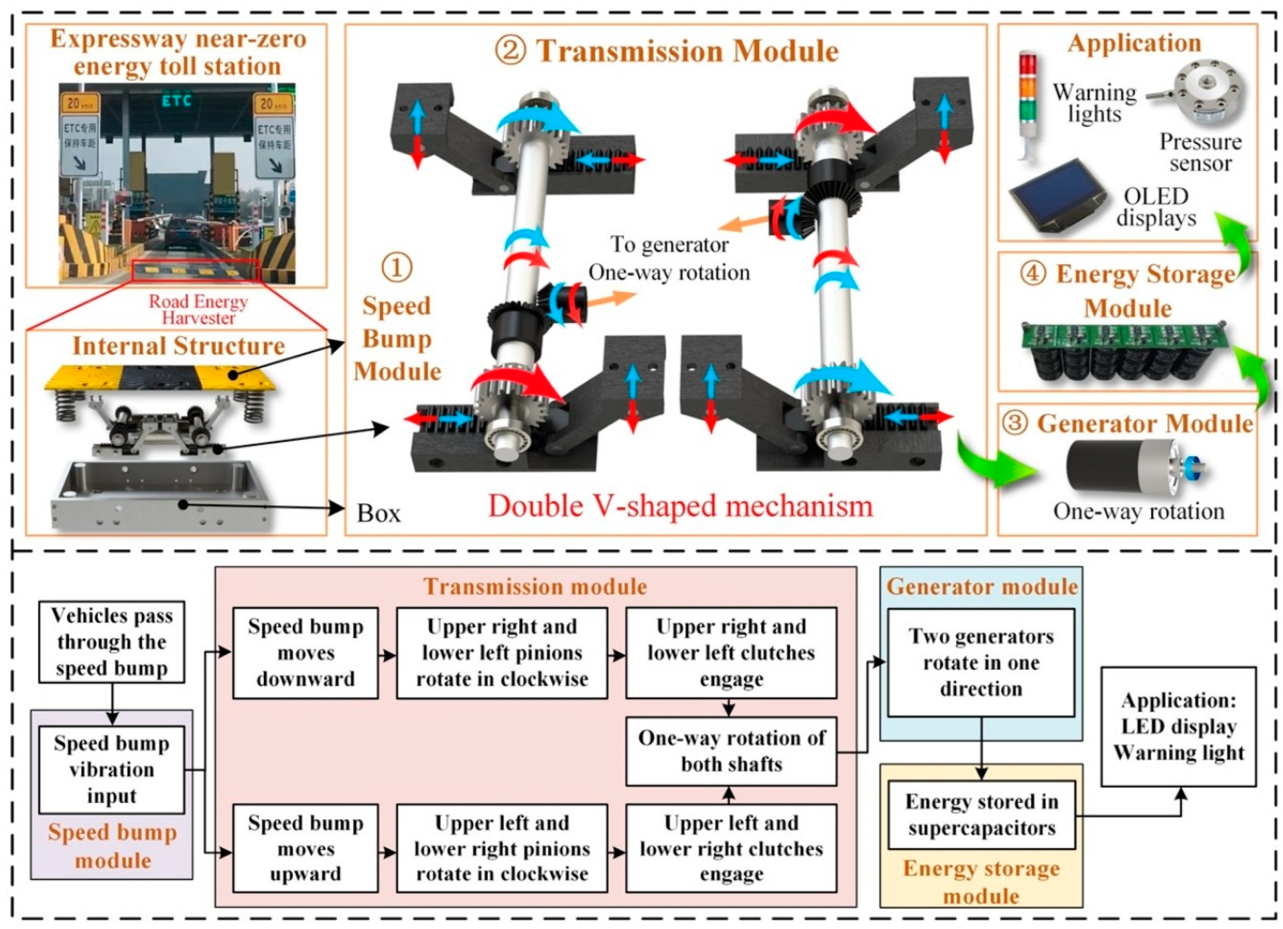
  115. Sun, M.; Wang, W.; Zheng, P.; Luo, D.; Zhang, Z. A Novel Road Energy Harvesting System Based on a Spatial Double V-Shaped Mechanism for near-Zero-Energy Toll Stations on Expressways. Sens. Actuators A Phys. 2021, 323, 112648. [Google Scholar] [CrossRef]
  116. Gholikhani, M.; Tahami, S.A.; Khalili, M.; Dessouky, S. Electromagnetic Energy Harvesting Technology: Key to Sustainability in Transportation Systems. Sustainability 2019, 11, 4906. [Google Scholar] [CrossRef] [Green Version]
  117. Zhang, Z.; Zhang, X.; Rasim, Y.; Wang, C.; Du, B.; Yuan, Y. Design, Modelling and Practical Tests on a High-Voltage Kinetic Energy Harvesting (EH) System for a Renewable Road Tunnel Based on Linear Alternators. Appl. Energy 2016, 164, 152–161. [Google Scholar] [CrossRef]
  118. Zhu, Y.; Yang, Z.; Jiao, C.; Ma, M.; Zhong, X. A Multi-Modal Energy Harvesting Device for Multi-Directional and Low-Frequency Wave Energy. Front. Mater. 2022, 9, 310. [Google Scholar] [CrossRef]
  119. Zhou, Q.; Park, J.G.; Kim, K.N.; Thokchom, A.K.; Bae, J.; Baik, J.M.; Kim, T. Transparent-Flexible-Multimodal Triboelectric Nanogenerators for Mechanical Energy Harvesting and Self-Powered Sensor Applications. Nano Energy 2018, 48, 471–480. [Google Scholar] [CrossRef]
  120. Orfei, F.; Orecchini, G.; Orfei, F.; Orecchini, G. Autonomous Sensors: Existing and Prospective Applications; IntechOpen: London, UK, 2014; ISBN 978-953-51-1218-1. [Google Scholar]
  121. Xiao, J.; Zou, X.; Xu, W. EPave: A Self-Powered Wireless Sensor for Smart and Autonomous Pavement. Sensors 2017, 17, 2207. [Google Scholar] [CrossRef] [PubMed]
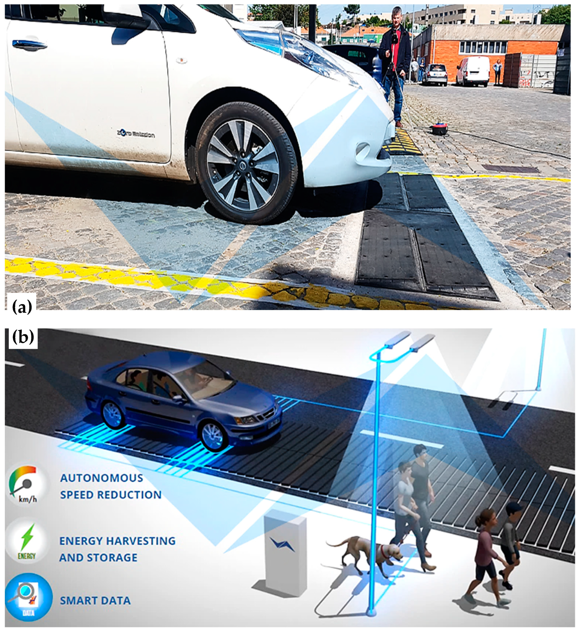
  122. Pavnext Technical Datasheet of Pavnext’s NEXT-Road. Available online: https://www.pavnext.com/applications/ (accessed on 19 February 2023).
  123. Duarte, F.J.A.; Lopes Ferreira, A.J.; Oliveira Fael, P.M. Device for Applying in a Pavement for Collecting Mechanical Energy from Vehicles Passing over for Generating Electricity. Patent 10,954,926, 27 February 2018. [Google Scholar]
  124. Nigg, J.L. Systems and Methods for Capturing Kinetic Energy and for Emission-Free Conversion of Captured Energy to Electricity. Patent 10,941,755, 28 February 2019. [Google Scholar]
  125. Pan, H.; Li, H.; Zhang, T.; Laghari, A.A.; Zhang, Z.; Yuan, Y.; Qian, B. A Portable Renewable Wind Energy Harvesting System Integrated S-Rotor and H-Rotor for Self-Powered Applications in High-Speed Railway Tunnels. Energy Convers. Manag. 2019, 196, 56–68. [Google Scholar] [CrossRef]
  126. Talaat, M.; Farahat, M.A.; Elkholy, M.H. Renewable Power Integration: Experimental and Simulation Study to Investigate the Ability of Integrating Wave, Solar and Wind Energies. Energy 2019, 170, 668–682. [Google Scholar] [CrossRef]
  127. AnterItalia Enlil, La Turbina Eolica Che Genera Energia Dal Traffico|Anter. Available online: https://anteritalia.org/enlil-la-turbina-che-genera-energia-dal-traffico/ (accessed on 22 February 2023).
  128. ENLIL-Vertical Axis Wind TurbineClimateLaunchpad. Available online: https://climatelaunchpad.org/finalists/enlil-vertical-axis-wind-turbine/ (accessed on 11 January 2023).
  129. Alpha 311—Local Renewable Energy for the World. Available online: https://alpha-311.com/case-studies/government/ (accessed on 11 January 2023).
  130. Toyabur, R.M.; Salauddin, M.; Cho, H.; Park, J.Y. A Multimodal Hybrid Energy Harvester Based on Piezoelectric-Electromagnetic Mechanisms for Low-Frequency Ambient Vibrations. Energy Convers. Manag. 2018, 168, 454–466. [Google Scholar] [CrossRef]
  131. Visconti, P.; de Fazio, R.; Velazquez, R.; Al-Naami, B.; Ghavifekr, A.A. Self-Powered WiFi-Connected Monitoring Stations for Environmental Pollution App-Based Control in Urban and Industrial Areas. In Proceedings of the 2022 8th International Conference on Control, Instrumentation and Automation (ICCIA), Tehran, Iran, 2–3 March 2022; pp. 1–6. [Google Scholar]
Figure 1. Available energy sources on a roadway (Reprinted with permission from Ref. [21]. 2018, Elsevier) [21].
Energies 16 03016 g001
Figure 2. Section of a vertical rack and pinion EH under a speed bump as a wheel approaches, passes, and leaves (Reprinted with permission from Ref. [26]. 2020, Taylor & Francis) [26].
Energies 16 03016 g002
Figure 3. A streetlamp lightened up thanks to the pressure of a car on a slab of PE harvesters.
Energies 16 03016 g003
Figure 4. List of triboelectric harvesting modes (Reprinted with permission from Ref. [51]. 2021, IOP Publishing) [51].
Energies 16 03016 g004
Figure 5. Magnetic-lifting TENG for energy harvesting application on the road (Reprinted with permission from Ref. [57]. 2021, AIP Publishing) [57].
Energies 16 03016 g005
Figure 6. Typical TEG harvesting system: schematic of the TEG prototype in pavement (GL, Ground level) (a), schematic diagram of the internal components of TEG (b) (Reprinted with permission from Ref. [65]. 2018, Springer Nature) [65].
Energies 16 03016 g006aEnergies 16 03016 g006b
Figure 7. Schematics of PSC implementations: (a) The water tank collects heated fluid, and the heat exchanger releases the heat into the environment (Reprinted with permission from Ref. [66]. 2019, Elsevier) [66]. (b) Road thermo-electric generator system (RTEGS) to convert heat into electrical energy, as presented in [67] (Reprinted with permission from Ref. [67]. 2018, Elsevier).
Energies 16 03016 g007
Figure 8. Classification of wind turbines (Reprinted with permission from Ref. [80]. 2020, Elsevier) [80].
Energies 16 03016 g008
Figure 9. Structures of two piezoelectric slab harvesters presented in [40] (Reprinted with permission from Ref. [40]. 2022, MDPI).
Energies 16 03016 g009
Figure 10. Piezoelectric device presented by Yuan et al. (2022): (a) output voltage vs. load resistance characteristic; (b) output power vs. load resistance characteristic; (c) 3D model; (d) realized prototype; (e) device under test (I) and trend of axial displacement as a function of stress cycles (II) (Reprinted with permission from Ref. [41]. 2022, Elsevier) [41].
Energies 16 03016 g010
Figure 11. (a) Experimental setup using pushing tester for three piezoelectric devices. (b) The URPG (15∗15) using 30 open-type devices: (i) real photo view, (ii) top view, and (iii) front view. (c) The URPG (30∗30) using 120 open-type devices: (i) real view, (ii) top view, (iii) front view, and (iv) housing module and the assembled module. (Reprinted with permission from Ref. [36]. 2022, Elsevier) [36].
Energies 16 03016 g011
Figure 12. Road test of the URPG: (a) Installation site. (b) Prototype of the URPG using 120 open-type devices: (i) real view, (ii) top view, (iii) front view and (iv) housing box and the assembled module. (c) Preparation of the road and test photos: (i) marking, (ii) cutting, (iii) leveling, (iv) filling with polyurethane paving, (v) schematic diagram of installation structure, (vi) installation, and (vii) vehicle test (Reprinted with permission from Ref. [36]. 2022, Elsevier) [36].
Energies 16 03016 g012
Figure 13. Design of electromagnetic energy scavenging module based on a double V-shaped mechanism [115]: the module’s structure, then a schematic of the elements (Reprinted with permission from Ref. [115]. 2021, Elsevier).
Energies 16 03016 g013
Figure 14. Prototypes of electromagnetic energy harvesting prototypes with rotational or cantilever mechanisms proposed by Gholikhani et al. in 2019: (a) Rotational mechanism prototype: (1) top plate; (2) bottom plate; (3) cylindrical support; (4) compression springs; (5) two-part rod; (6) lever; (7) box with magnets, coils, gears, and torsional springs. (b) Cantilever-mechanism prototype: (8) rod, (9) spring arm, (10) arm support, (11) magnets, (12) electrical coil (Reprinted with permission from Ref. [116]. 2019, MDPI) [116].
Energies 16 03016 g014
Figure 15. Waterbomb origami-based TENG: (a) Bidimensional schematic of the origami structure for the TENG’s PET substrate. (b) Bidimensional representation of the disposition of the materials constituting the tribo-couple. (c) Three-dimensions view of the disposition of the materials forming the tribo-couple. (d) WO-TENG prototype. (e) Folded WO-TENG. (f) Application of the WO-TENG to the road (Reprinted with permission from Ref. [55]. 2022, Springer Nature) [55].
Energies 16 03016 g015
Figure 16. PV asphalt pavement block proposed by Hossain in 2021: (a) Three-layer model. (b) Prototype (Reprinted with permission from Ref. [70]. 2021, MDPI) [70].
Energies 16 03016 g016
Figure 17. Thermoelectric system proposed by Xie et al.: (a) Four different commercial TEGUs. (b) Aluminum heat sinks. (c) TEGUs connected in series and arranged in a matrix. (d) Lateral view (Reprinted with permission from Ref. [74]. 2022, Springer Nature) [74].
Energies 16 03016 g017
Figure 19. (a) Schematic of the Roadway Energy X (REX) tile, (b) real view of REX system, a rumble strip box buried in the roadway to harvest electricity with every vehicle pass, (c) REX system installed on the road with the car driving over it. (d) road retarder with integrated REX tile to recover energy from passing cars (Reprinted with permission from Ref. [124]. Constructis Group Inc., Virginia Beach, VA, USA) [124].
Energies 16 03016 g019
Figure 20. PVNB in Neuötting, built by Maxsolar company [63].
Energies 16 03016 g020
Figure 21. (a) Operation scheme of the Alpha 311 turbine, (b) application of Alpha 311 turbines in the road’s median, properly designed to be retrofitted to existing infrastructure such as streetlights alongside roads. (Reprinted with permission from Ref. [129]. Alpha 311 Ltd., Kent, UK) [129].
Energies 16 03016 g021
Table 1. Comparison between different technologies for energy harvesting from roads.
TechnologyReferencesEnergy SourcePlacementCharacteristicsOrder of Magnitude of Scavenged Power
Electromagnetic[4,7,21,23,24,25,26,27,28,29]Vibration, mechanical stressSpeed bumpsLocalized, involves large constructions100’s of W
Piezoelectric[5,21,30,31,32,33,34,35,36,37,38,39,40,41,42,43,44,45,46,47]Vibration, mechanical stressRoadway layers (surface, base, sub-base)High efficiency, implementable everywhere, some toxic materials100’s of µW/cm2
(Wind)(Roadside)
Triboelectric[14,15,48,49,50,51,52,53,54,55,56,57]Vibration, mechanicalRoadway layers (surface, base, sub-base)High efficiency, implementable everywhere100’s of µW/cm2
(Wind)(Roadside)
Photovoltaic[58,59,60,61,62,63]Solar radiationAsphalt pavement surface, noise barriers, road tunnels, and road roofsLocalized, high efficiency, easy accessibility for maintenance, could require much maintenance, depends on weather100’s of mW/cm2
Thermoelectric[6,21,64,65,66,67,68,69,70,71,72,73,74,75]Heat, solar radiationUnderneath the roadBenefits for the road (reduced urban heat, increased road lifetime, de-icing). Depends on weather10’s of mW/cm2
Wind turbines[76,77,78,79,80,81,82,83,84,85]WindRoadsideLocalized, easy access to maintenance10’s of W
Table 2. Elastic modulus and electromechanical conversion coefficient of the PE devices presented in [40].
Applied Pressure Amplitude (MPa)Device’s Unit TransducerElastic Modulus/MPa (with 10 Hz Stress)Conversion Coefficient/% (with 5 Hz and 10 Hz Stress)
0.5Pile5887.9 (5 Hz), 8.2 (10 Hz)
Bridge5646.9 (5 Hz), 7.1 (10 Hz)
0.7Pile5948.2 (5 Hz), 8.4 (10 Hz)
Bridge4927.1 (5 Hz), 7.2 (10 Hz)
0.9Pile6048.4 (5 Hz), 8.3 (10 Hz)
Bridge4857.5 (5 Hz), 7.1 (10 Hz)
Table 3. Comparison of different energy harvesting solutions along roads found in the literature.
AuthorsDeveloped DeviceType and Specifications of the Input StressTechnical FeaturesCharacteristics and Strengths
Lin et al.
[39]
Drum PE harvesterMechanical stress at 1 Hz superposed to confining pressure. Both stress and pressure can vary in amplitude.AC output. In saturated moisture conditions: 70 V maximum output voltage, 3.4 mW maximum output power. In optimum moisture conditions: 35 V, 3.3 mWEasy fabrication, relatively small dimensions, high output voltage
Li et al.
[40]
Pile (or bridge) unit-based piezoelectric energy harvesterSinusoidal mechanical stress at 5 and 10 Hz frequencies and 0.5, 0.7, and 0.9 MPa.For pile unit transducer: 300 V max output voltage, 3.4 mW maximum output power.
For bridge unit transducer: 100 V max output voltage, 2.6 mW max output power.
Modular, high output voltage.
Yuan et al.
[41]
Road-compatible piezoelectric power generation deviceCyclic mechanical 0.7 MPa stress at 3, 7, 9, and 11 Hz.Variable output.
96 V maximum output voltage, 102.4 mW maximum output power.
Modular, high output voltage. Good durability: >7 months
Liu et al.
[42]
Radially layered cymbal piezoelectric energy harvesterSinusoidal mechanical 500 N stress at 20, 25, and 30 Hz superposed to a constant 1100 N clamping stress.Variable output.
53.6 V maximum output voltage, 0.92 mW maximum output power.
Small dimensions
Jeon et al.
[43,44]
Bending-type piezoelectric energy harvesterCyclic mechanical stress at 3.35 Hz, leading to a 1 mm displacement.60.3 mW maximum output power.Modular. Good durability: >146,000 cycles
Ennawaoui et al.
[45]
Smart speed bumpCyclic mechanical stress at different frequencies and strain values.2.72 V maximum output voltage.Speed bump
Cho et al.
[35]
Multifunctional road-compatible piezoelectric energy harvesterCyclic mechanical 300 kg stress at 15 Hz.Variable output.
113.5 V maximum output voltage, 661 mW maximum output power. 17.2% conversion efficiency.
Big dimension. High output voltage. Good durability: >5 months
Hwang et al.
[46]
Road-compatible piezoelectric energy harvesterCyclic mechanical stress at 15 Hz, causing 2 mm displacement.DC output (with rectifier).
34 V maximum output voltage, 850 mW maximum output power.
Big dimension.
Wang et al.
[47]
Road spring-type piezoelectric transducerCyclic mechanical stress at frequencies 2, 4, 6, 8, 10 Hz, causing displacements of 0.5, 1, 2 mm.DC output (with rectifier).
For the planar unit-based harvester: 6.335 mW maximum output power.
For the spring unit-based harvester: 14.183 mW maximum output power.
Good durability. Speed bump.
Sun et al.
[115]
Road energy harvesting system based on a spatial double V-shaped mechanismMechanical square wave stress, from 350 to 500 N of amplitude, at 0.1 Hz. 10 mm maximum displacement.Variable output.
12.64 V maximum output voltage, 1.1 W maximum output power.
Output power and voltage increasing with input frequency. Conversion efficiency decreases by increasing input frequency. Speed bump.
Gholikhani et al.
[26]
Electromagnetic Speed bump Energy harvester (ESE)Haversine wave mechanical stress with 3, 5, or 10 kN and loading and unloading times.Variable output. 16.5 W maximum output power.Output varies a lot with loading conditions and spring stiffness. Adaptability to many traffic conditions. Speed bump.
Gholikhani et al.
[116]
Electromagnetic energy harvesting prototype with rotational or cantilever mechanismHaversine wave mechanical stress with 3, 5, or 10 kN and 300, 600, or 900 ms of loading and unloading times.For the harvester with rotational mechanism: 0.04 W maximum RMS output power. For the harvester with cantilever mechanism: 0.43 W maximum RMS output power.Speed bump. For rotational mechanism harvester, power generation only during descending movement. For cantilever mechanism harvester, power generation during descending and ascending phases.
Zhang et al.
[117]
High-voltage kinetic energy harvesting systemMoving 2255 kg car at 20, 30, or 40 km/h.AC output. 194 V maximum output voltage (positive peak), 55.2 average output voltage (positive peak).Speed bump.
Zhang et al.
[56]
Origami-Tessellation-based TENG (OT-TENG)Mechanical stress with varying frequency (from 3 to 16 Hz).AC output.Compact, with many slots to insert tribo-couples. Exploits vertical compressive, horizontal compressive, and tensile stress inputs. No need for springs. Low cost. Easy fabrication. Waterproof. Lightweight. Good durability >40,000 cycles at 10 Hz.
Pang et al.
[44]
Waterbomb Origami-inspired TENG (WO-TENG)Sinusoidal mechanical stress at frequencies (10, 15, and 25 Hz).AC output.Compact, with many slots to insert tribo-couples. Easy fabrication. Waterproof. Lightweight. Good durability: >57,600 cycles at 16 Hz.
Yang et al.
[15]
Multi-mode triboelectric nanogenerator (M-TENG) DC output (with rectifier)
Bani-Hani et al.
[84]
Road Darrieus three-bladed VAWTWind at different speeds on the highwayMaximum output power: 48 WEasy accessibility for maintenance. High output power depends on weather and traffic conditions
Magade et al.
[85]
Mini wind turbineWind source at various distances from the turbine, from 0 to 10 m/s,Maximum output voltage: 24 V. Maximum output power: 60 WEasy accessibility for maintenance. High output power. Depends on the weather and traffic conditions. Lightweight but weak material
Hossain et al.
[70]
Road photovoltaic module for the self-powered light system at crosswalksSolar radiation on the road, between April and May 2019, for 40 min every dayMaximum output power: 2.26 WLoss of efficiency if shaded. Loss of efficiency over time because of dust accumulation. Depends on weather and traffic conditions
Zhou et al.
[69]
Pavement-integrated photovoltaic/thermal system (PIPVT)Radiation from two 500 W halogen lampsMaximum output voltage: 18.9 V. Maximum output power: 29.3 WDepends on the weather and traffic conditions. Lower electrical efficiency than other thermal modules but higher thermal efficiency
Angel et al.
[71]
Asphalt Heat Recovery ApplicationSolar radiation on a road-Passive system
Mona et al.
[72]
TEG system used for harvesting energy from a roadTemperature gradient between the road pavement’s underside and the cooling system (either natural airflow or water bath)Variable output. Maximum output voltage: 49.6 mV for cement road and natural airflow, 77.6 mV for cement road and water bath, 134.4 mV for asphalt road and natural airflow, 168.5 mV for asphalt road and water bathDepends on weather conditions and road materials. Underground placement
Wei et al.
[73]
Thermoelectric energy harvesting system for pavements with a fin-cooling structureTemperature gradient between 2 cm underneath the road and the heat sinksVariable output. Maximum output voltage: 0.3 VDepends on weather conditions. Underground placement. Low cost, long life
Xie et al.
[74]
Pavement Thermoelectric Energy Harvesting SystemTemperature gradient in field test, on a sunny winter day, from 9° to 17° of air temperature.Variable output. Maximum output voltage: 5.582 V. Maximum output power: 0.623 WDepends on weather conditions. Underground placement
Tahami et al.
[75]
Thermo-Electric Energy Harvesting Module for Asphalt RoadwayTemperature gradient during the field testVariable output. Maximum output power: 47.14 mW.Depends on weather conditions. Underground placement
Table 4. Wattway module’s specifications [61].
Specifications
Module Area0.69 m2
Number of active cells28
Nominal Power (Pnom)125 W
Maximum Power Point Voltage (VMPPT)15.1 V
Maximum Power Point Current (VMPPT)8.27 A
Open Circuit Voltage (VOC)18.5 V
Short-Circuit Current (ISC)8.7 A
Junction Box ConnectorIP68
Dimensione Modulo1257 mm × 690 mm
Thickness 6 mm
Impact ResistanceIK 07
Road Performance 1 × 10⁶ of passages of 13 tons wheel
Table 5. Comparison between different commercial solutions for energy harvesting along roadsides.
Commercial SolutionType and Specifications of the Input StressTechnical FeaturesCharacteristics and Strengths
Pavnext’s NEXT-road [122]Road trafficMaximum output power for 20 m of NEXT-road: 10 Wh for a single vehicle, 3.65 MWh in a yearModular. Produced power could be stored in the loco or transferred to the grid. Traffic data are produced along with power
Constructis’s Rex
[124]
Road trafficMaximum output power: 100 kWh per moduleModular. Works from −20 F to 140 F. Produced power could be stored in the loco or transferred to the grid. Traffic data are produced along with energy.
Wattway
[61]
Sunlight on the roadMaximum output voltage: 60 V per panel. Nominal power: 125 Wc per panelModular
Maxsolar’s PV noise barriers [63]Sunlight around roadsYearly power production for a 234 m application: 58 MWhModular. Easy accessibility for maintenance
ENLIL
[127]
Low-speed wind around roadsMaximum output power: 1 kWh per turbineModular. Easy accessibility for maintenance
Disclaimer/Publisher’s Note: The statements, opinions and data contained in all publications are solely those of the individual author(s) and contributor(s) and not of MDPI and/or the editor(s). MDPI and/or the editor(s) disclaim responsibility for any injury to people or property resulting from any ideas, methods, instructions or products referred to in the content.

