1. Introduction
Recently, producing electrical power from renewable energy resources has become an imperative and a promising means of green electrical power generation because of the decline in traditional fossil energy reserves [
1]. Worldwide, the integration of renewable energy sources (RESs) into conventional electricity grids is expanding quickly. While decentralizing the production of bulk power plants, the RESs and distributed generators (
) may increase variations and disturbances due to the changing nature and uncertainties of RESs. For eliminating the limitations of interconnecting RESs/DGs to the grid, a microgrid (
) has been suggested as a suitable infrastructure [
2]. Moreover, the reduced-order H controller significantly boosts the microgrid frequency control performance when compared to the best PI-based virtual inertia controller, increasing microgrid stability and resilience. With the increase in penetration levels of RESs, and due to the electrical connection of RESs to electric power grids or μG, the total inertia of the system is decreased, which reduces the overall system inertia and causes high-frequency fluctuations, which are considered indicative of the stability of the electrical power system [
3,
4].
The virtual emulation of the behavior of the synchronous generator (VSG) into
is a viable approach for enhancing system inertia, stability, and resilience. A virtual inertia control (VIC) has been proposed to address these issues in highly invasive renewable energy systems [
5,
6]. The VIC is regarded as a special form of VSG implementation, where the prime mover’s movement is simulated to provide frequency stability. To increase the set point of active power and the islanded
frequency stability, the virtual inertia control is applied based on the function of the Rate of Change of Frequency (RoCoF) [
7,
8]. For the steady performance of
, the balance between demand and supply in real-time is a vital step in order for the frequency to remain constantly in its acceptable range. Furthermore, the energy storage units may act as a load or as a power source to minimize frequency variations [
9,
10,
11,
12]. The VIC technology is based on the RoCoF, where the active power absorbed from or injected into the storage device is proportionate to the RoCoF where active power is emulated from energy storage systems (ESS) commensurate with the frequency deviation. The VIC technology prepares the microgrid to deal with expected disturbances, such as a loss in generation units, large frequency and voltage fluctuations, faults, and forced load shedding [
13].
Many control technologies have been executed based on the VIC to maintain the stability of the
frequency [
2,
14,
15,
16,
17,
18]. In [
14], the derivative controller is applied to enhance the stability of an interconnected power system frequency. To enhance the frequency stability and performance of interconnected systems with significant RESs penetration, a novel application of virtual inertia control-based derivative control approaches is presented in this work. The fuzzy logic control has been proposed as a VIC technique to enhance an isolated microgrid frequency stability [
2,
16]. The model predictive control (MPC) is developed for the implementation of the VIC to withstand the RESs’ high penetration levels in an isolated
[
17]. The VIC based on the frequency response estimation method is developed to improve the power system stability [
18]. The author in [
19] develops the VIC based on different technologies to enhance an isolated
inertia and frequency stability.
The energy storage system (ESS) has been in existence for a long time and has been utilized in many forms and applications. Energy storage devices are included in the power system to raise stability and reliability as well as to make wider use of RESs a reality; the ESS can convert RESs from non-dispatchable power resources into a dispatchable electrical power source [
20]. The energy storage application can be divided into three categories: mechanical, electrical, and chemical energy storages, as listed in [
21]. There are many types of electrical energy storage devices, such as batteries, flywheels, supercapacitors, and superconducting magnetic energy storage (SMES), as listed in [
22]. The SMES has been introduced previously in a variety of applications, increasing system efficiency overall in the presence of RESs. The study examined the implementation of a SMES and battery hybrid energy storage system in a small-scale off-grid wind power system. SMES and batteries were successfully hybridized to create a stable and quick-responding hybrid energy storage system to reduce wind power variations and balance the supply and demand for power [
23].
Hydrogen energy is generally considered the most possible environmentally friendly energy source in the twenty-first century [
24]. It has received international interest because of its clean, pollution-free features, efficient storage and transportation, and high consumption rate [
25,
26]. A hydrogen energy storage system (HESS) is a chemical storage technique that converts chemical energy to electrical energy [
24,
27]. Hydrogen (
) storage has been shown to be an appropriate choice as a chemical energy storage system in μGs [
28,
29,
30]. Hydrogen energy solutions have recently been considered in several areas, mainly power applications. In [
31,
32], an energy management method for an isolated μG with a hydrogen production and storage system is provided. Technical feasibility and stability can be improved under disturbances, including low-voltage ride-through (LVRT) capacity and oscillation mitigation concerns after incorporating the ESS in the wind turbine systems [
9]. The application of hydrogen energy in tramways by fuel cells is described in [
33], which may significantly increase system flexibility and minimize environmental pollution. During low load demand,
may be produced on-site, employing excess electricity from RESs [
34]. The produced
can be stored in an
cylinder and used by a fuel cell (FC) to generate power when the load demand is higher than the RES production [
35]. The extra generated power from RESs, such as wind power (WP) or photovoltaic (PV) modules, is applied to an electrolyzer. There are several types of electrolyzers in the market, such as alkaline water electrolyzers (AWEs) [
36], proton exchange membrane electrolyzers (PEMEs) [
37], and solid oxide electrolyzers (SOECs) [
38].
Water electrolysis has been demonstrated to be an effective method for producing
in
[
39]. Hydrogen is an energy carrier that can be produced by splitting water molecules into hydrogen and oxygen molecules in an electrolyzer. The process is known as electrolysis, and the chemical processes that occur require electricity as an energy source. Following that, the generated hydrogen can be kept until it is further transported to fulfill end-use energy demands. According to the observations of the prior research, a hydrogen energy system can provide more load flexibility and long and short-term energy storage while simultaneously posing new problems to
control.
Remote areas face many challenges, such as sudden changes in loads, as well as sudden changes in weather conditions and radiation. Moreover, the presence of renewable energy sources, such as solar energy, reduces the inertia of the system. It is vital to utilize the enormous potential of supplying frequency management and regulating electricity to ensure safety. As a result, substantial research has been conducted to produce more effective frequency controllers for . The following contributions are made by this paper:
Proposing a new VSG method based on the SMES system to improve the frequency stability of ultra-low-inertia power grids while accounting for high levels of RES penetration.
The suggested virtual controller (PI controller) is a composite of a virtual primary and virtual secondary controller.
The solar power stations were divided into several small stations to restore stability of the μG at a high penetration level of RES and low load demand.
Employing HESS to utilize the whole power generated from RES without power curtailment.
The rest of the paper is organized as follows:
Section 2 introduces the modeling and structure of the studied
;
Section 3 presents the proposed VIC technology; and
Section 4 introduces a comparison of two solutions to overcome
disorders. The work is concluded in
Section 5.
2. System Dynamics of an Isolated Microgrid
To illustrate the control strategy presented in this work, a hybrid
with hydrogen and battery storage is constructed as depicted in
Figure 1. The investigated system is divided into five parts: DEG, RESs, HESS, SMES, and loads [
40]. To simulate system operation and control, the hybrid
is investigated in
Figure 1 and is modeled using MATLAB Simulink. The studied
here consists of three sections. The first is the generation and load section; the generation can be represented by the DEG, PVs, and WTs, while the second is the storage section, which contains a hydrogen storage system that consists of AWEs, a hydrogen storage tank, and
The efficiency of the AWEs is 54% and the efficiency of the micro-gas turbine is 40%. Hence, the round efficiency of the HESS is 21.6%. The third and last is the virtual inertia control section, which contains SMES and PID control. The
is fed by a DEG with 950 kW, 1256 kW of photovoltaic arrays, 41 units with each unit producing 30.6 kW and 591.3 kW of wind power, and 30 units with each unit produces 19.7 kW. The energy storage is accomplished via SMES and HESSs including electrolyzers,
tanks, and a
as another energy storage and domestic load, with a maximum value of 950 kW [
41].
2.1. Deisel Engine Generator (DEG)
The diesel engine generator (DEG) is used as a backup source if renewable energy sources and a storage system are insufficient to fulfill the load power requirements. Several studies on DEG modeling have been conducted [
42,
43].
Figure 2 depicts a model of a prime mover and governor for the DEG. The DEG may be represented by the first-order conversion function stated in Equation (1).
where
represents the overall
DEG time constant taking in mind the governor time constant, generator time constant, and inertia delay time constant, which can be calculated as [
44].
where
is the rated angular velocity and
is the moment of inertia
is the apparent power (VA).
2.2. Photovoltaic System
The solar irradiance model, as depicted in
Figure 3, is given using the following equation,
where
δ is defined as the photovoltaic array conversion efficiency and always ranges from 9% to 12%;
S is the panel area in
, ∅ is the solar radiation;
is the ambient temperature in degrees Celsius.
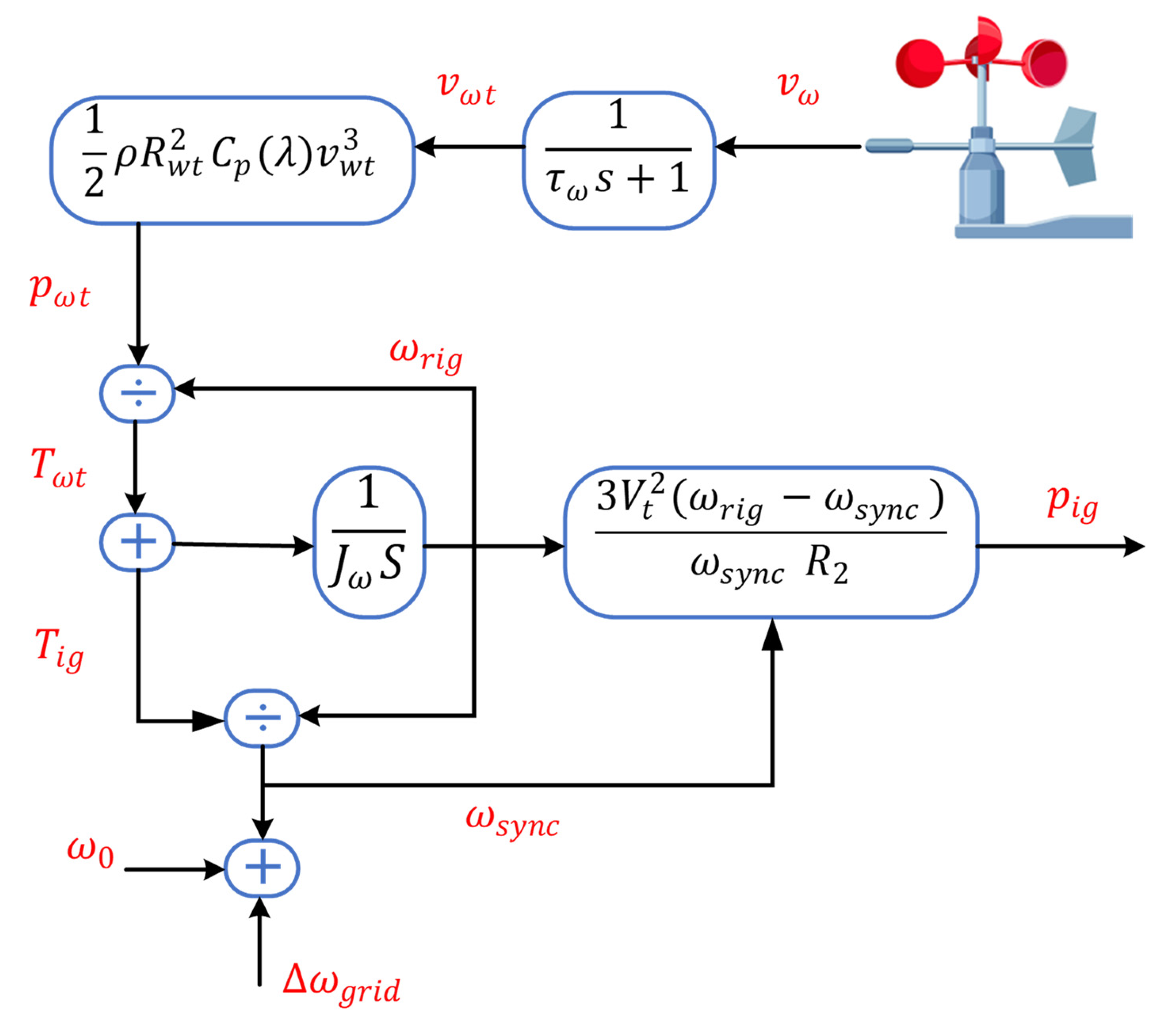
2.3. Wind Turbines
For the WTG system, the following equation was often employed to compute the mechanical power output of wind turbines. The wind turbine output mechanical power can be expressed as:
where
is the density of air (
is the radius of the blade (
),
is the wind speed
, and
is the power coefficient defined as a function of the tip speed ratio [
45]. The wind turbine is coupled with the induction generator (IG) through the gearbox, as shown in
Figure 4.
2.4. Process Model of HESS
Hydrogen is an energy carrier that can be produced by splitting water molecules into hydrogen and oxygen molecules in an electrolyzer. The process is known as electrolysis, and the chemical process requires electricity as an energy source. Following that, the generated hydrogen is kept until it is further transformed to fulfill end-use energy demands.
If the end-use requirement is electricity, the conversion can be carried out using a fuel cell, which combines hydrogen molecules with oxygen to generate water and energy. Hence, the conversion of power-to-power through HESS comprises three parts:
Thus, HESS is classified into three separate subsystems. This section delves deeper into the technology of these subsystems.
2.4.1. Hydrogen Production—Electrolyzer
Several types of electrolyzers may be classified by the kind of electrolyte, operating temperature, and used charge carrier. The most commonly used techniques are the proton exchange membrane electrolyzer (PEMEL), alkaline electrolyzer (AEL), and solid oxide electrolyzer (SOEL). The AELs are used in this article because they are the most mature electrolyzer technologies in the market, with lower investment costs and greater efficiency than the PEMEL and SOEL [
24]. The electrolyzer runs in the current mode and the electrolyzer operating voltage is given as [
46], the designed AWE is shown in
Figure 5, and the parameters have been listed in
Table A4.
The total power consumed by one group of the electrolyzers is as follows [
47].
where
is the current flow through one group is and
cell is the number of cells in one group. The electrolyzer operates in current mode. The operating voltage of an electrolyzer is given using [
48].
where
is the operating temperature of the electrolyzer,
and
are parameters related to the internal resistance of the electrolyzer, in which
reflects the change in internal resistance with temperature.
,
,
, and
are related to overvoltage caused by the polarization of electrodes and electrolytes.
and
reflect the over-voltage with the change in temperature.
,
,
,
, and
are all empirical parameters, which can be measured via experiments. The reversible open circuit voltage
reflects the minimum potential between electrodes when every single electrolytic monomer is electrolyzing water. The hydrogen flow rate (
) can be calculated using:
2.4.2. Micro GAS Turbines
The
is a generation means that converts the chemical energy that is stored in the form of hydrogen into electrical power. Chemical energy, unlike batteries, is not contained in the device, so the conversion process requires a constant supply of fuel, as shown in
Figure 6. The main
components are the compressor, combustion chamber, turbine, and generator. There are additional parts to enhance the
performance, such as a recuperator, in which the cooled air is exchanged with the hot gas [
49], an economizer heat exchanger, which heats the water with exhaust gas having left the recuperator, and an evaporative cooler, which mixes the water with compressed air [
50].
The
fuel mass flow rate (
) can be calculated as follows [
41]:
where
n is the
speed, the
generated active power can be calculated as follows:
where
is the
efficiency and
is the lower heating value.
2.5. Design of VIC Based on the SMES Device
The VIC part consists of two main segments [
51]: the first is the SMES and the other is the control system. The control system manages the SMES by using a PID controller [
52,
53]. The block diagram of the SMES is shown in
Figure 7.
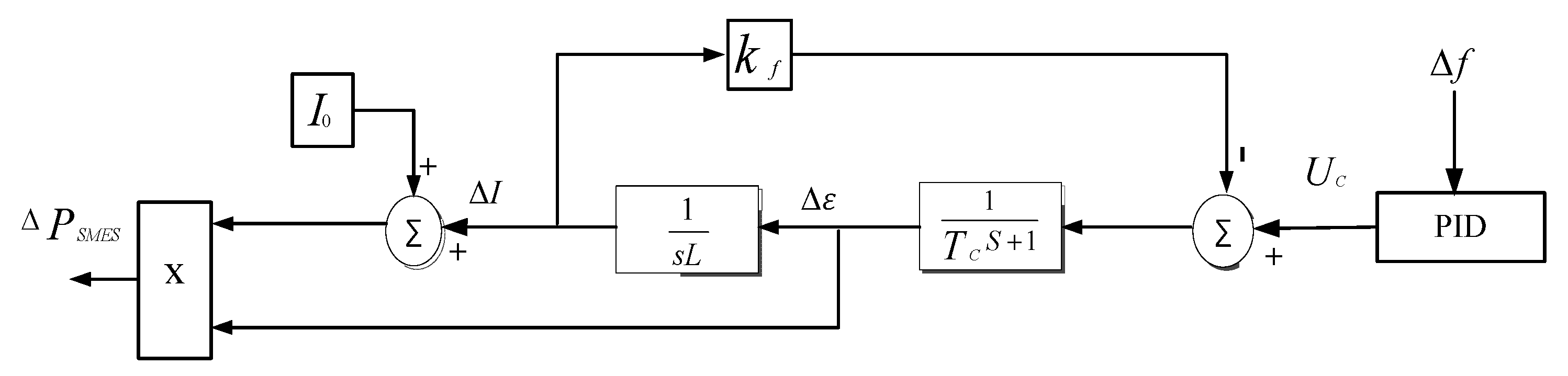
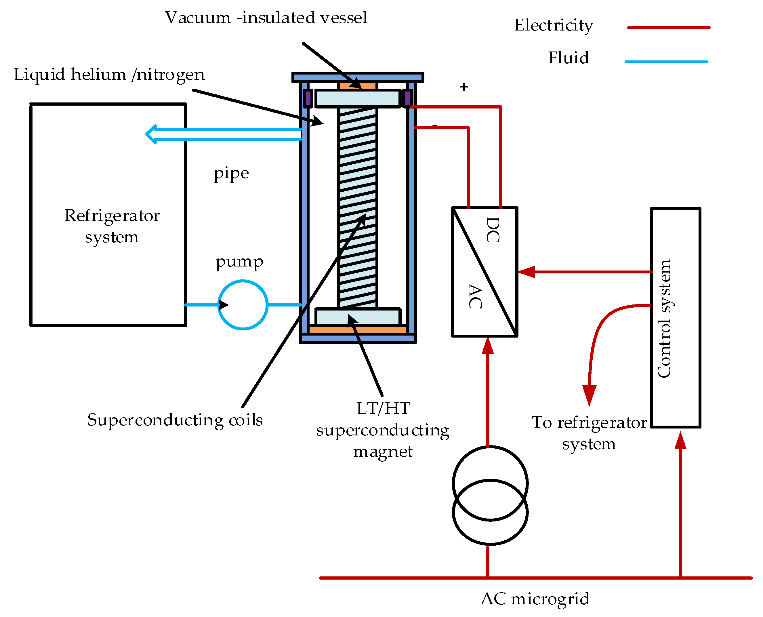
Mathematical Model of SMES Device
The magnetic coil, which is made of a special superconducting material with nearly zero resistance, is the central component of the SMES system [
54]. As long as the SMES coil is kept superconducting, a zero-energy loss can be guaranteed, resulting in high efficiency. By immersing the SMES coil in a helium vessel, it should be cooled to the superconducting temperature [
54].
Figure 8 illustrates the SMES construction [
54].
The stored energy (
) in the superconducting coil can be calculated from:
where
L is the coil inductance.
The rated power
of the superconducting coil can be described using the following equations:
The change in SMES output power can be calculated from:
where Δ
ε the gradual change in the SMES inductor applied voltage and can be calculated as follows:
where
is the inductor current deviation feedback gain and Δ
I is the SMES inductor current deviation and can be calculated using:
3. Virtual Inertia Control System
In conventional power systems, the kinetic energy (
) inherent in the rotational mass, including spinning loads, represents the inertia power response, and can be calculated as follows [
55]:
where
j is the moment of inertia of the power system in
and
ω is the angular frequency deviation in
The power system inertia constant (
) can be calculated using [
56]:
where
, is the rated apparent power. The relationship between frequency and active power in a
is as follows:
where
is the
inertia coefficient,
is the sum of the
output active power,
is the sum of the needed loads,
is the
damping coefficient, and Δ
f is the frequency deviation.
The
SMES system is used to provide virtual inertia for μG due to its quick response characteristic. As a result, the overall frequency characteristic of the μG can be described as:
According to the previous equation, adding an SMES system to the improves the inertia and damping of the . The can obtain a robust frequency characteristic by selecting the appropriate coefficient.


 ,
, 


