Article

Improved Adaptive Droop Control Design for Optimal Power Sharing in VSC-MTDC Integrating Wind Farms

State Key Laboratory of Advanced Electromagnetic Engineering and Technology, Huazhong University of Science and Technology, Wuhan 430074, China
*
Author to whom correspondence should be addressed.
Energies 2015, 8(7), 7100-7121; https://0-doi-org.brum.beds.ac.uk/10.3390/en8077100
Submission received: 28 April 2015 / Revised: 24 June 2015 / Accepted: 7 July 2015 / Published: 14 July 2015
(This article belongs to the Special Issue Electrical Power and Energy Systems for Transportation Applications)

Abstract

:
With the advance of insulated gate bipolar transistor (IGBT) converters, Multi-Terminal DC (MTDC) based on the voltage-source converter (VSC) has developed rapidly in renewable and electric power systems. To reduce the copper loss of large capacity and long distance DC transmission line, an improved droop control design based on optimal power sharing in VSC-MTDC integrating offshore wind farm is proposed. The proposed approach provided a calculation method for power-voltage droop coefficients under two different scenarios either considering local load or not. The available headroom of each converter station was considered as a converter outage, to participate in the power adjustment according to their ability. A four-terminal MTDC model system including two large scale wind farms was set up in PSCAD/EMTDC. Then, the proposed control strategy was verified through simulation under the various conditions, including wind speed variation, rectifier outage and inverter outage, and a three-phase short-circuit of the converter.

1. Introduction

Renewable energy especially large scale wind power generation, is rapidly becoming an alternative to traditional generation technologies due to less pollutant emission. However, large scale wind farms are often located in remote areas. Given the large capacity and long distance wind power bulk, the high voltage direct current (HVDC) based on voltage source converter (VSC) is considered to be a feasible solution to transmitting wind power because of its great advantages [1]. VSC-HVDC can control active and reactive power independently, especially as it is able to provide black-start capability [2,3], whose typical topology of two-terminal VSC-HVDC system is shown in Figure 1. Multi-terminal DC (MTDC) grids are foreseen as an alternative solution to point-to-point connections owing to their increased redundancy and higher flexibility [4]. Intensive researches have recently been conducted to resolve various technical issues in the VSC-MTDC system, such as locating and isolating of DC faults [5], operation and control of MTDC grid integrating wind farms and so on [6,7]. In order to improve the capacity and stable operation of MTDC, X. Chen et al. [8] have studied the control methods of hybrid MTDC grid integrating wind farms, and proposed corresponding control strategies. B. Silva and his colleagues [9] have done researches into fault ride through capacity of VSC-MTDC grid. However, there are few studies on control strategies for reducing the copper loss of MTDC grid integrating wind farms under different operation condition.
Figure 1. Configuration of voltage-source converter-high voltage direct current (VSC-HVDC) system.
Energies 08 07100 g001
The stable operation condition of VSC-MTDC is to guarantee the constant DC voltage control. DC voltage control mainly includes two types of control strategy: One is the master-slave scheme [10,11], and the other is DC voltage droop control [12,13]. Master-slave control needs communication system between different converters. One of the converters is chosen to control DC voltage of VSC-MTDC to compensate power losses, which is similar with the role of a slack bus in an AC power system, while other converters utilize the constant power control scheme. The duty of DC voltage droop control is to share imbalanced instantaneous power among two or more VSC terminals according to value of slopes [14]. As for the above control strategies, the active and/or reactive power reference or values of slopes will change the power flow of whole power system, thus affecting copper loss of VSC-MTDC system. According to Haileselassie’s study [12], DC voltage droop control is considered more reliable than the master-slave scheme due to power balancing, so steady operation of MTDC grids should not depend on a main VSC-HVDC terminal.
Then there are two problems we will face: One is how to reduce copper loss as VSC-MTDC operates steadily, the other is how VSC-MTDC will react to power imbalance caused by the outage of one or more converter stations. The concept and working principle of droop control have been proposed for power sharing and frequency through VSC-MTDC grid [15,16,17]. Haileselassie’s group [12] has discussed the impact of DC voltage drops on distribution of DC grid balancing power, and concluded that the DC voltage droop coefficient determined the degree of power sharing. Rouzbehi et al. [18] has studied the voltage-droop strategy based on optimal DC power flow, all converters operate normally. However, the references above merely considered fixed droop coefficient, ignoring actual operational condition of VSC-MTDC. In another study, Chaudhuri et al. [19] considered the particular operating condition of each converter, presented available headroom, and proposed an adaptive droop control scheme for appropriate power sharing. In our study, to solve the two problems of VSC-MTDC above, an improved droop control would be proposed to minimize copper loss of the whole MTDC system integrating large scale wind farms under two different scenarios considering local load or not. On the basis of reducing copper loss, the available headroom of each converter station is taken into account in case of the outage, and then an adaptive improved droop control is proposed to improve the dynamic response ability of converters.
The rest of this paper is organized as follows. Modeling and control of MTDC are introduced in Section 2, followed by Section 3 and Section 4 which propose the improved droop control strategy and post-contingency operation state. Then we validated this droop control of VSC-MTDC in EMTDC/PSCAD in Section 5, and drew conclusions in Section 6.

2. Modeling and Control of MTDC

In terms of the point-to-point VSC-HVDC links, one converter station is used to maintain DC link voltage which acts as a slack/swing converter station. The other stations operate in power control mode to ensure the scheduled power exchange.

2.1. Converter Modeling

The main circuit topology of converter for VSC-HVDC is composed of a conventional two-level six-bridges pulse width modulation (PWM) voltage source converter [20,21], which is shown in the Figure 2. In Figure 2, U s refers to fundamental component of AC bus voltage, U c is the fundamental component of converter’s output voltage, δ is the angle that U ˙ c lags to U ˙ s parameter R and X are the inductance and resistance of phase reactor of the VSC respectively, and capacitor C f represents the shunt filter.
Figure 2. Main circuit topology diagram of voltage source converter.
Energies 08 07100 g002
Ignoring the resistance R and harmonic components, the active and reactive power absorbed by VSC-HVDC system is given in [22], because the angle δ is very small, then sin δ = δ , cos δ = 1 active and reactive power absorbed by VSC are described as follows
{ P = U s U c X δ Q = U s ( U s U c ) X
where, X = ω L is the reactance of the inverter; ω is the nominal angular frequency of AC system. Figure 2 shows a schematic diagram of VSC connected to an AC grid. The AC-side dynamics of the converter can be expressed by the following equation
U s a b c U c a b c = L d i a b c d t + R i a b c
where, i a b c represents the current flowing through interfacing reactor and coupling transformer.
A synchronous d-q reference approach is conventionally employed to facilitate VSC-HVDC control, and the positive-sequence three-phase voltages U s a b c and currents i a b c are transformed to d-q components U s d q and i d q using Park Transformation.
U s d q = U d + j U q = 2 3 j e j ω t ( U s a + e j 2 3 π U s b + e j 2 3 π U s c )
i d q = i d + j i q = 2 3 j e j ω t ( i a + e j 2 3 π i b + e j 2 3 π i c )
where, U s d and U s q are the voltage at d-axis and q-axis respectively; i d and i q are the current at d-axis and q-axis respectively. In the synchronous d-q reference frame, the dynamics of VSC in Equations (3) and (4) can be expressed as follows
U s d U c d = L d i d d t + R i d ω L i q
U s q U c q = L d i q d t + R i q + ω L i d
where, U c d = M U d c sin δ / 2 ; U c q = M U d c cos δ / 2 .
The instantaneous active and reactive power absorbed by VSC in dq-axis are given in [23], which could be described as follows
{ P = 1.5 U s d i d Q = 1.5 U s d i q
It can be seen from Equation (1), the angle and amplitude of ac voltage for VSC-HVDC system determine the absorbing of active and reactive power, and the following expressions could be obtained
(i)
Angle of phase shifting: δ = arctan U c q U c d
(ii)
Modulation index: M = U c d 2 + U c q 2 U d c / 2
Therefore, according to U c d , U c q and U d c of VSC, both of the modulation index M and angle δ are obtained, to realize the independent control of active power and reactive power of VSC-HVDC.

2.2. Control Method of VSC-MTDC Integrating Wind Farm

As for the long distance and large transmission capacity VSC-MTDC system, the copper loss is substantial due to large resistance and imperfect power distribution of each DC power transmission line. To reduce copper loss of VSC-MTDC, we proposed an improved droop control strategy, the basic idea of which is as follows: Any one inverter converter of VSC-MTDC is chosen as a benchmark converter, and fixed droop control method is used, then the signals of power output for benchmark inverter station are transmitted to other inverter stations. Droop coefficient of other inverter stations would be adjusted according to power difference between benchmark inverter stations and other ones adaptively. The concrete implementation process will be realized in the following paragraphs.
In this paper, a four-terminal HVDC system will be considered two large-scale offshore wind farms are integrated into this four-terminal HVDC system. As is shown in Figure 3, each offshore wind farm contains its local AC network to connect individual wind farms, and each feeder is to convert the AC into DC fed to the HVDC network.
Figure 3. Wind farms integration in a four-terminal HVDC system.
Energies 08 07100 g003
In Figure 3, there are two wind farms feeding power by cables 1 and 2 which are joined together with cable 5 at the offshore connection point. The transmitted power is then divided among cables 3 and 4 into two VSC stations. In general, the control strategies for sending and receiving feeders for VSC are different. In this study, the VSCs of sending feeder and receiving feeder are controlled by power synchronization control, and offshore VSC is connected to the wind farm. The control strategy is holding a constant magnitude of ac voltage and frequency so that power generated by wind farm can be dispatched. In addition, the control strategy of onshore VSC is holding a constant DC voltage, to realize the power balance of VSC-MTDC system.

2.2.1. Control of VSC for Offshore Wind Farm

The equivalent circuit of wind farm connected to VSC station is shown in Figure 4. Ignoring resistance R and harmonic components of VSC, voltage and current of ac side are described as follows
{ C 1 p U W M = I W M I C V R 1 I C V + L 1 p I C V = U W M U C V
In the analysis, Equation (8) is expressed in dq-axis coordinate system, which is given by
{ I W M d I C V d = C 1 p U W M d ω C 1 U W M q I W M q I C V q = C 1 p U W M q + ω C 1 U W M d
{ U W M d U C V d = ( R 1 + p L 1 ) I C V d ω L 1 I C V q U W M q U C V q = ( R 1 + p L 1 ) I C V q + ω L 1 I C V d
where, p = d/dt is differential operator.
Figure 4. Equivalent circuit of wind farms connected to VSC station.
Energies 08 07100 g004
According to Equation (9), voltage loop control would be built, then reference value of current loop control can be obtained
{ I C V d ref = [ k p 1 ( U W M d ref U W M d ) + k i 1 ( U W M d ref U W M d ) d t ] + I W M d + ω C 1 U W M q I C V q ref = [ k p 1 ( U W M q ref U W M q ) + k i 1 ( U W M q ref U W M q ) d t ] + I W M q ω C 1 U W M d
Then the d-axis is coincidence with ac voltage vector, U W M d r e f = 1 , U W M q r e f = 0 . According to Equation (10), current loop control would be described as follows
{ U C V d ref = [ k p 2 ( I C V d ref I C V d ) + k i 2 ( I C V d ref I C V d ) d t ] + U W M d + ω L 1 I C V q U C V q ref = [ k p 2 ( I C V d ref I C V d ) + k i 2 ( I C V d ref I C V d ) d t ] + U W M q ω L 1 I C V d
Simplified schematic diagram of control strategy is shown in Figure 5. Back-to-back PWM converters are used for variable speed wind power generation.
Figure 5. Control block diagram of VSC offshore wind farm.
Energies 08 07100 g005

2.2.2. Control of VSC for Onshore Stations

Onshore VSC stations would be controlled by improved adaptive droop control method. Firstly, this control strategy is holding a constant DC voltage and realizing the power balance of VSC-MTDC system. Secondly, the optimal power distribution between DC transmission lines will be realized, and copper loss of VSC-MVDC system will be reduced. The diagram of the improved adaptive droop control strategy for onshore VSC is shown in Figure 6.
Figure 6. Control block diagram of onshore VSC.
Energies 08 07100 g006

3. Improved Adaptive Droop Control in VSC-MTDC

3.1. Fixed Droop Method

As for two terminal VSC-HVDC links, one station operates in active power control mode to ensure scheduled active power, the other operates in DC voltage control mode to provide constant DC voltage for the system and supply power loss due to line resistance, which acts as a slack VSC converter station. As for VSC-MTDC grid, if one or more converters follow an outage, remaining ones should share power gap in certain appropriate proportion. Droop coefficient is very important at different converter stations in that it determines how a power imbalance will be shared among converters, which has been discussed in [12]. If droop coefficient is identical, remaining converters are required to share power imbalance at equal ratio. On the other hand, if droop coefficient is unequal, the higher ones would have dominant contribution from active power control loop.
However, actual load condition has not been considered in a fixed droop control. In fact, if a converter follows an outage, some converters may achieve the upper limit of their capacity, though they are unable to share more power imbalance. In addition, the issue needs to be settled as to how much power ratio should be shared for each remaining station to realize minimum copper loss of VSC-MTDC. Adaptive droop control can solve these problems and will be described in the next subsection.

3.2. Design for Minimum Copper Loss

The relationship of power sharing between receiving end feeders is shown in Figure 7. It can be seen from Figure 7 that U t and I t are the voltage and current at sending end, U G S x and U G S y are the receiving end converter voltages, I G S x and I G S y are receiving end currents, R G S x and R G S y are resistance at receiving end. The voltage equations of receiving end for VSC-MTDC system are expressed as
{ U t = U G S x + I G S x R G S x U t = U G S y + ( I t I G S x ) R G S y
Figure 7. Power sharing between receiving end feeders.
Energies 08 07100 g007
The copper loss of VSC-HVDC between receiving end feeders is given by
P c o p p e r l o s s s = R G S x I G S x 2 + R G S y ( I t I G S x ) 2
Then Equation (14) is differentiated with respect to I G S x , then equating to zero. According to reference [24], the power sharing ratio for minimum copper loss between two feeders is inversely proportional to feeder resistances
d P c o p p e r l o s s s d I G S x = 2 R G S x I G S x 2 R G S y ( I t I G S x ) = 0
P G S x P G S y = R G S y R G S x
The power loss is minimized if the voltage magnitudes of different receiving end converters are the same [24]. If there are n cables between receiving end feeders, the power sharing ratio for minimum copper loss of VSC-MTDC system is as follows
P G S 1 : P G S 2 : : P G S n = 1 R G S 1 : 1 R G S 2 : : 1 R G S n

3.3. Improved Adaptive Droop Control

To reduce copper loss of VSC-MTDC grid, optimal strategy of power sharing based on discussions in the paragraph above is proposed, and the concrete implementation process is as follows. As for the MTDC grid, the first inverter converter is operated by fixed droop, which is given by [19]
U d c _ s l a c k 2 ( U d c 1 ref ) 2 4 + k 1 d r o o p ( P G S 1 ref P G S 1 ) = 0
In this paper, the common DC reference voltage U d c , s l a c k is introduced as reference voltage of MTDC system, whose value is chosen from the converter with DC link voltage control mode. The fixed droop coefficient of the first inverter converter is described as follows
k 1 d r o o p = ( U d c 1 , min ref ) 2 U d c _ s l a c k 2 4 ( P G S 1 ref P G S 1 max )
where, U d c , min is minimum value of DC link voltage; P G S i max is the maximum value of active power for converter i. Then the improved droop control of the ith converter is given by
U d c _ s l a c k 2 ( U d c i ref ) 2 4 + k i d r o o p ( P G S i ref P G S i ) = 0
k i d r o o p = k 1 d r o o p + m i ( P G S 1 P G S i )
Then, m i is defined as the power difference coefficient between the benchmark inverter station and other inverter ones, which will be deduced in the following paragraphs.
(1)
Inverter converter without local load
In terms of inverter converter station, if δ = 0 , and P G S i = 0 ; if δ 0 , the fundamental component of converter’s output voltage is described as follows
U c i = P G S i X i U s δ
From Equations (18), (20) and (22), if δ = 0 , then
k i d r o o p ( P G S i ref P G S i ) k 1 d r o o p ( P G S 1 ref P G S 1 ) = 0
Substituting Equations (21) into (23), then expression of power difference coefficient of inverter stations m i is obtained as follows
m i = | k 1 d r o o p [ ( P G S i ref P G S i ) + ( P G S 1 P G S 1 ref ) ] ( P G S i ref P G S i ) ( P G S 1 P G S i ) |
Similarly, if δ 0 , m i is given by
m i = | k 1 d r o o p [ ( P G S i ref P G S i ) + ( P G S 1 P G S 1 ref ) ] + ( P G S i 2 X i 2 P G S 1 2 X 1 2 ) / ( 4 U s 2 δ 2 ) ( P G S i ref P G S i ) ( P G S 1 P G S i ) |
(2)
Inverter converter with local load
As for the first inverter converter station, if δ = 0 , P G S i = 0 ; if δ 0 , then fundamental component of converter’s output voltage is given by
U c i = ( P G S i P l o a d i ) X i U s δ
If δ = 0 , m i is shown in Equation (24). Similarly, according to Equations (18), (20) and (26), if δ 0 , m i could be obtained as follows
m i = | k 1 d r o o p [ ( P G S i ref P G S i ) + ( P G S 1 P G S 1 ref ) ] + [ ( P G S i ref P l o a d i ) 2 X i 2 ( P G S 1 ref P l o a d 1 ) 2 X 1 2 ] / ( 4 U s 2 δ 2 ) ( P G S i ref P G S i ) ( P G S 1 P G S i ) |
where, P l o a d 1 and P L o a d i are local load of the first and ith inverter converter respectively; and the data of m i could be obtained according to communication device of system.
In terms of fixed droop control, if the rating of converter stations is identical, a power imbalance caused by an outage would be shared equally with other remaining converter stations. However, some converter stations may not be able to participate in power sharing equivalently due to the actual operating condition of the system. Therefore, available headroom of the ith converter is defined as [19]
ν i = κ i | P i |
k i a d r o o p = k i 0 d r o o p ( κ max ν i ) τ
where, κ i is rated capacity of the ith converter; ν i is remaining capacity of the ith converter; k i 0 d r o o p and k i a d r o o p are improved adaptive droop coefficient under pre-outage and post-outage operating conditions, respectively; κ max = max ( κ 1 , κ 2 , , κ n ) refers to maximal value of all converters’ capacity; and τ is a user defined positive constant, whose value of and modal analysis of adaptive droop are discussed in [19].

4. Post-Contingency Operation

In this section, operating point of post-contingency for VSC-MTDC will be proposed. Assuming there are n converter stations in MTDC system, the active power must maintain real-time balance, which will satisfy
i = 1 n P i + P l o s s e s = 0 , i = 1 n P i ref = 0
where, P i and P i ref are the actual active power and active power reference value of the ith converter respectively. Moreover, total real power loss caused by DC line resistance is P l o s s e s = i = 1 n P i . According to voltage droop control strategy, improved adaptive droop control for pre-outage under steady state is described as follows
( U d c i ref ) 2 U d c _ s l a c k 2 = 4 P l o s s e s i 1 k i 0 d r o o p
P i = P i ref P l o s s e s k i 0 d r o o p i 1 k i 0 d r o o p
If the converter outage of MTDC system is introduced at the nth converter, that is
i = 1 n 1 P i ref = P n ref i = 1 n 1 P i = P l o s s '
where, P l o s s ' is total real power loss when converter outage is introduced at the nth converter.
Following the outage of the nth converter, the steady operating point at post-contingency for VSC-MTDC system will be changed, which is given by
( U d c i ref ) 2 ( U d c _ s l a c k ' ) 2 = 4 ( P l o s s e s ' P n ref ) i = 1 n 1 1 k i a d r o o p
P i ' = P i ref P l o s s e s P n ref 1 k i a d r o o p i = 1 n 1 k i a d r o o p
Comparing the operating point between pre-outage and the post-outage, the power changes for the ith converter is described as
Δ P i = P i ' P i = P l o s s e s k i 0 d r o o p i 1 k i 0 d r o o p P l o s s e s P m ref 1 k i a d r o o p i = 1 m 1 k i a d r o o p
There is some differences involved improved adaptive droop coefficient between the inverter converter stations with or without local load. Figure 8 and Figure 9 show corresponding droop strategies for the VSC-MTDC system.
Figure 8. Block diagram of improved adaptive droop scheme without local load.
Energies 08 07100 g008
Figure 9. Block diagram of improved adaptive droop scheme with local load.
Energies 08 07100 g009
In addition, the tuning values of PI parameters for designed controller could be described from the following aspects:
In terms of the PWM converter, initial value and steady-state value of reactive current iq are nearly equal to zero, it is not obvious change with the tuning of controller parameters. The response curves of id need to be studied in detail to ensure the parameters of controllers. In terms of PI parameters KP and KI of current inner loop, the basic principle is that does not increase overshoot amount and also ensure response speed of designed controller. The best tuning values of PI parameters for current loop are as follows
τ 2 = L R , K 2 = L 2 T PWM
where, T PWM = T s / 2 , and T s is the switch time period of PWM.
In terms of PI parameters KP and KI of voltage loop, if the KP increases, the intensity of voltage rising will be improved; if the KI increases, which can accelerate the speed of voltage into without static error state. Therefore, the best tuning values of PI parameters for voltage loop are described
τ 1 = 2 R e q C , K 1 = C U dcN 2 T PWM U s
where, the equivalent resistance R eq = U dcN 2 / P N .
In addition, the best tuning values of PI parameters for power outer loop are given by
τ 1 =10 T PWM , K 1 = 1 2.24 U s
Therefore, the best tuning values of PI parameters for current loop, voltage loop and power loop of designed controller could be obtained according to Equations (37)–(39).

5. Simulation and Discussion

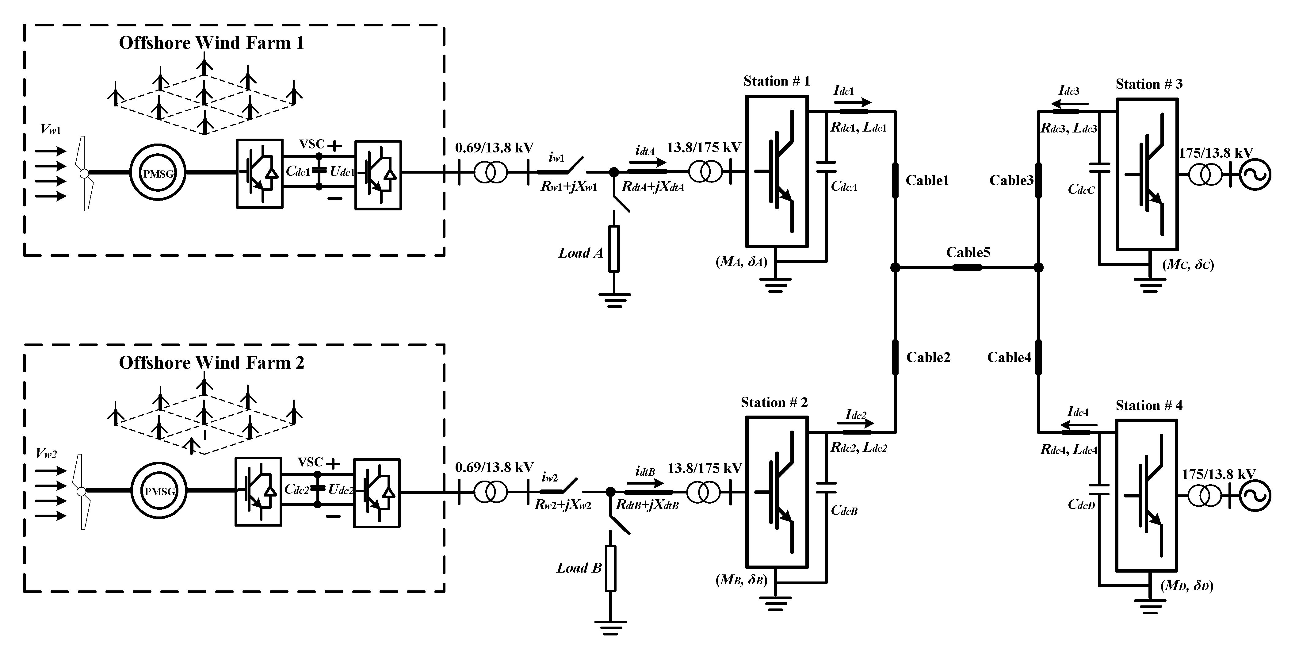
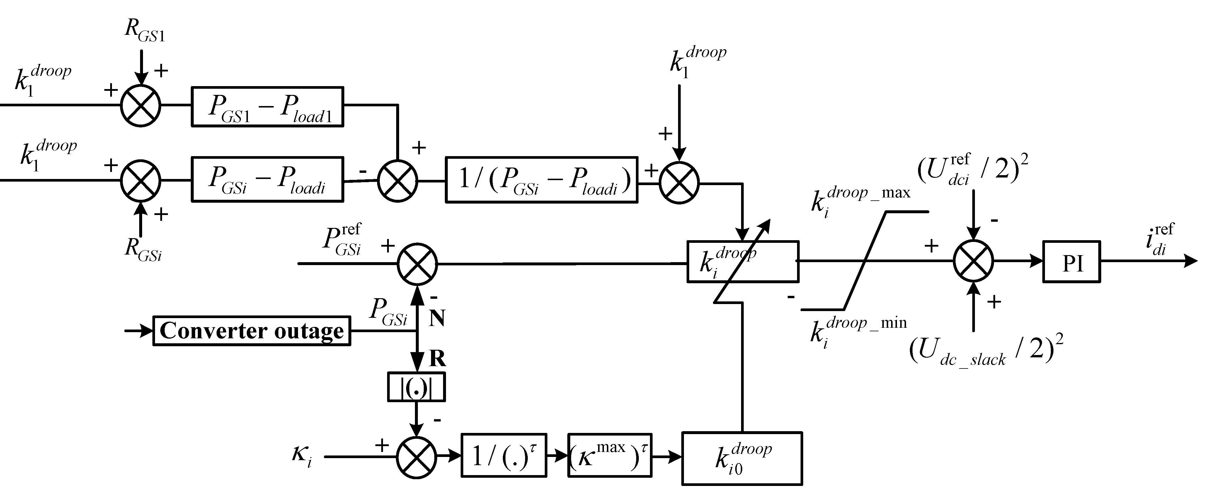
The improved adaptive droop control of VSC-MTDC have been implemented by PSACD/EMTDC, and the configuration and control system of VSC-MTDC is shown in Figure 3. Four-terminal HVDC system is a bipolar scheme with a nominal 300 kV DC voltage. The wind farm is modeled as one aggregated PMSG driven by a single equivalent wind turbine. Parameters of DC cables and communicating transformers are displayed in Table 1 and Table 2 respectively. The total rated capacity of MTDC grid is about 2180 MVA, and rated ac voltage is 175 kV, τ = 2.5, κ max = 900 MW.
Table 1. Parameters of DC Cables.
Number of Cable12345
Resistance/Ω0.010850.010850.0086750.0162750.04
Reactance/H0.00020.00020.000150.0030.015
Distance/km20205080100
Table 2. Parameters of Commutating Transformers.
ConvertersLeakage ReactanceCapacityTransformer Ratio
VSC10.15 (pu)440 MVA175 kV/13.8 kV
VSC20.15 (pu)440 MVA175 kV/13.8 kV
VSC30.15 (pu)900 MVA175 kV/13.8 kV
VSC40.15 (pu)400 MVA175 kV/13.8 kV

5.1. Wind Speed Variation

The performance of a VSC station integrated with wind farms is investigated in the case of variable wind speed, and the simulation results are shown in 
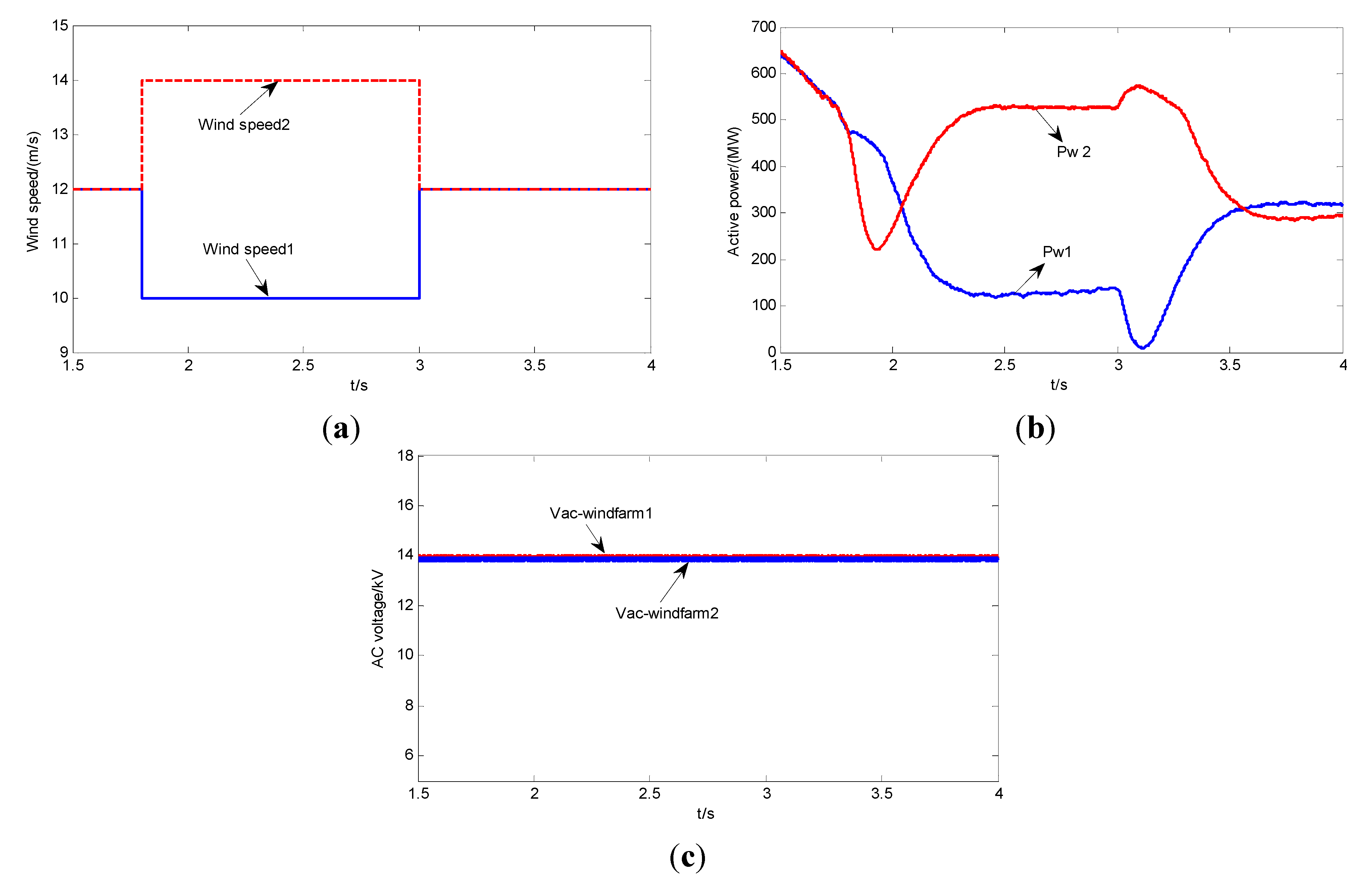
Figure 10. The gust wind speed of wind farm 1 and 2 are introduced at 1.8 s and 3.0 s with the fluctuation, slowing down from 12 to 10 m/s and ramping up from 10 to 12 m/s for wind farm 1, ramping up from 12 to 14 m/s and slowing down from 14 to 12 m/s for wind farm 2 in 
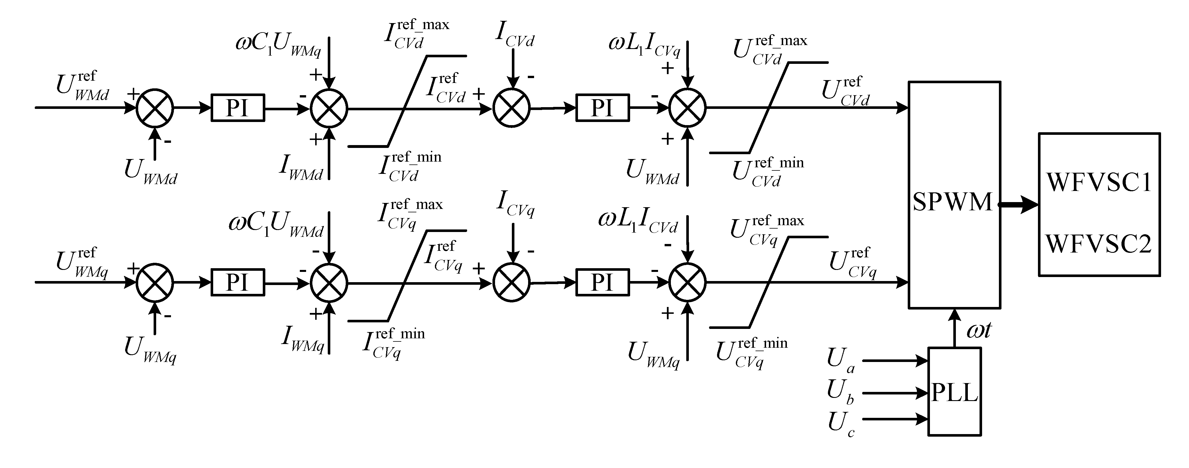
Figure 10a. To collect the stochastic wind power, the ac side needs to supply constant ac voltage for the wind farm network and absorb fluctuant power automatically.
Figure 10. Simulation result with variation wind speed. (a) Wind speed; (b) AC voltage for different wind farm; (c) Active power on wind farm side.
Energies 08 07100 g010
With the increased or decreased wind speed at 1.8 s and 3.0 s, it can be seen from Figure 10b that active power generated by wind farm rose or fell near to a constant value, thus the control strategy of wind turbine can follow the wind speed fluctuation effectively. In addition, it can be seen from Figure 10c that the ac voltage on the wind farm side was held at 13.8 kV throughout the wind speed fluctuation as the control strategy designed. Corresponding to the power variation of the VSC rectifier side due to the wind speed change, then slack converter (VSC inverter side) would take effect to balance power flow in VSC-MTDC system.

5.2. Normal Operation of VSC-MTDC

In this section, the performance of the fixed droop control and improved adaptive droop control are compared under normal operation condition. For fixed droop, droop coefficient of station #4 is equal to 0.03418, the one at station #3 is 0.01519 according to their converter ratings. In terms of improved droop control, station #4 is a benchmark converter station whose droop coefficient is constant. The one at station #3 is 0.1424 under the condition of optimal power sharing, which is much larger than the one of reference [19]. Therefore, station #3 would share much more power transmission to reduce the copper loss of VSC-MTDC grid, and τ = 2.5 was used for the improved adaptive droop control. Five different operational scenarios for inverter side converter station #3 and #4 are investigated, which mainly includes P3ref/P4ref = 6, 3, 1, 1/3 and 1/6. Table 3 and Table 4 show results of copper loss of VSC-MTDC without or with local load respectively.
Based on the above discussion, if there are two DC lines in inverter side of VSC-MTDC, the condition obtained for minimum copper loss is that P3ref/P4ref = R4/R3 = 3.001. From Table 3 and Table 4, the minimum copper loss is about 16.7382 MW (without local load) and 16.6435 MW (with local load) respectively when P3ref/P4ref = 3.0. In addition, if the capacity ratio of P3ref/P4ref is much greater or smaller than the optimal ratio value 3.0, all the reduced copper loss are larger than the ones of optimal ratio.
Table 3. Copper loss of VSC-HVDC (without local load).
Capacity RatioDroop ControlProposed Method
P3ref/P4ref = 617.0368 MW [12]16.8933 MW
P3ref/P4ref = 316.8793 MW [18]16.7382 MW
P3ref/P4ref = 117.3963 MW [12]17.1495 MW
P3ref/P4ref = 1/318.1844 MW [12]17.8648 MW
P3ref/P4ref = 1/619.0705 MW [12]18.7209 MW
Table 4. Copper loss of VSC-HVDC (with local load).
Capacity RatioDroop Control [ 12]Proposed Method
P3ref/P4ref = 617.0156 MW [12]16.8672 MW
P3ref/P4ref = 316.7841 MW [18]16.6435 MW
P3ref/P4ref = 117.3718 MW [12]17.1211 MW
P3ref/P4ref = 1/318.1528 MW [12]17.8232 MW
P3ref/P4ref = 1/619.0115 MW [12]18.6413 MW
The capacity ratio of P3ref/P4ref is inverse proportion to optimal ratio value of the resistance of DC line 3 and 4, and improved adaptive droop control is used for VSC-MTDC without local load and the dynamic responses of four-terminal HVDC are shown in 
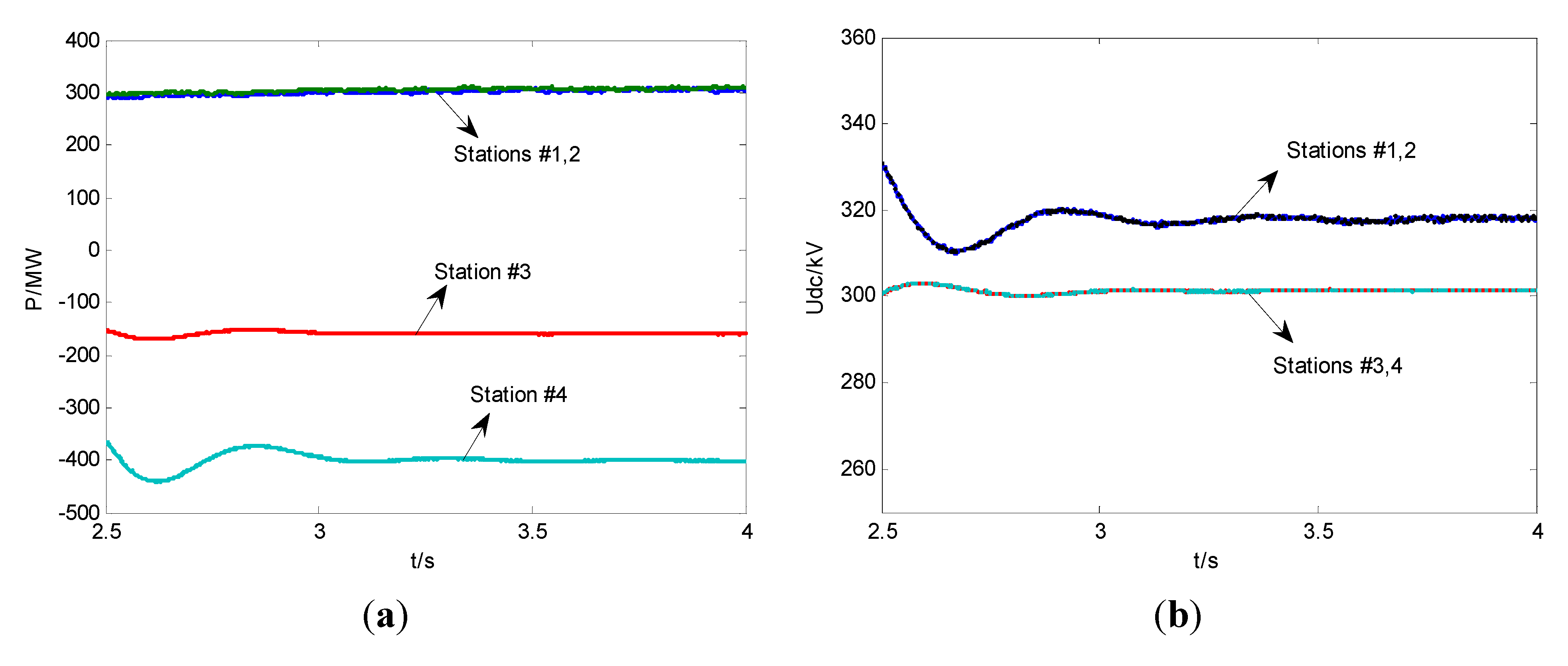
Figure 11. It can be seen from 
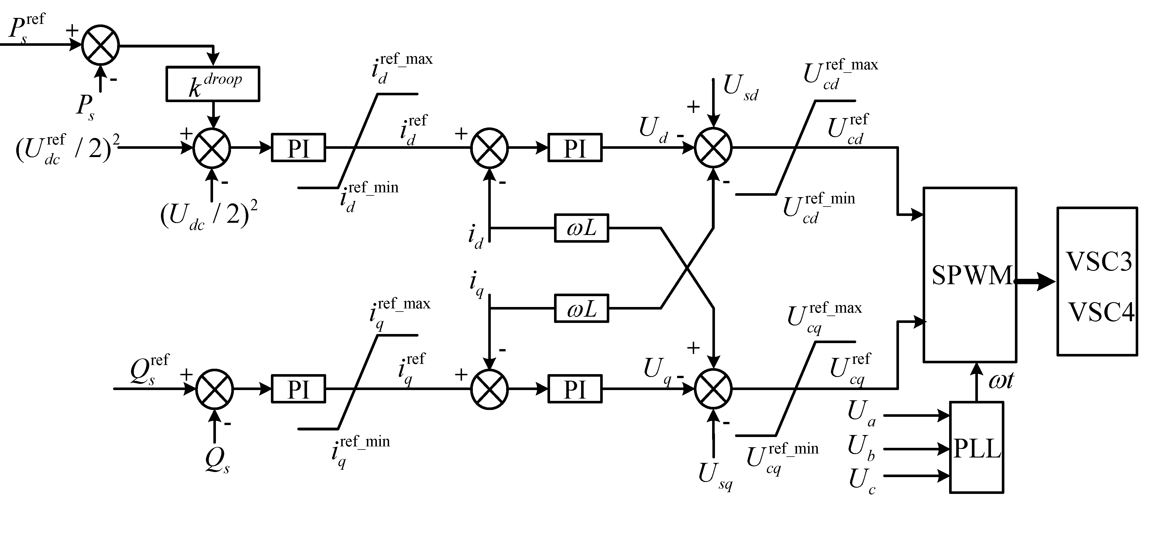
Figure 11a,b that converter station can follow the power reference value quickly, among which stations #1 and #2 export about 300 MW. In addition, due to the obvious DC voltage loss caused by large resistance of DC line, voltage of rectifier side (stations #1 and #2) is about 306 kV and voltage of inverter side (stations #3 and #4) is about 300 kV that is hold by the introduced common DC voltage Udc_slack. If DC line resistance of VSC-MTDC system increases, the voltage loss would be greater.
Figure 11. Dynamic response of normal operation (a) Active power (b) DC side voltage.
Energies 08 07100 g011

5.3. Converter Outage of VSC-MTDC

In this section, the performance of the fixed droop and improved adaptive droop scheme is compared in the case of a converter outage. Unequal loading conditions are considered to demonstrate the benefit of the improved adaptive droop. If a DC fault of converter appears, the differential protection will be actuated. When a certain current level is reached, IGBTs would be blocked. As DC breakers have not been used, it is necessary to block converter stations and to use AC circuit breakers to clear the fault. In this case, both rectifier and inverter converter outages are simulated which represent two different operational scenarios.
(1) Inverter Outage: In the first case, stations #3 and #4 imports 465 MW and 155 MW, respectively. Stations #1 and #2 export around 620 MW into the DC grid. The outage of station #4 is considered. The results of copper loss of VSC-MTDC without/with local load are shown in Table 5. It can be seen from Table 5, the amounts of copper loss without/with local load reduced from 16.7124 MW and 16.6357 MW to 16.5131 MW and 16.4265 MW as the optimal power sharing of VSC-HVDC grid (P3ref/P4ref = 3), which are more effective for improved droop control than the ones of reference [
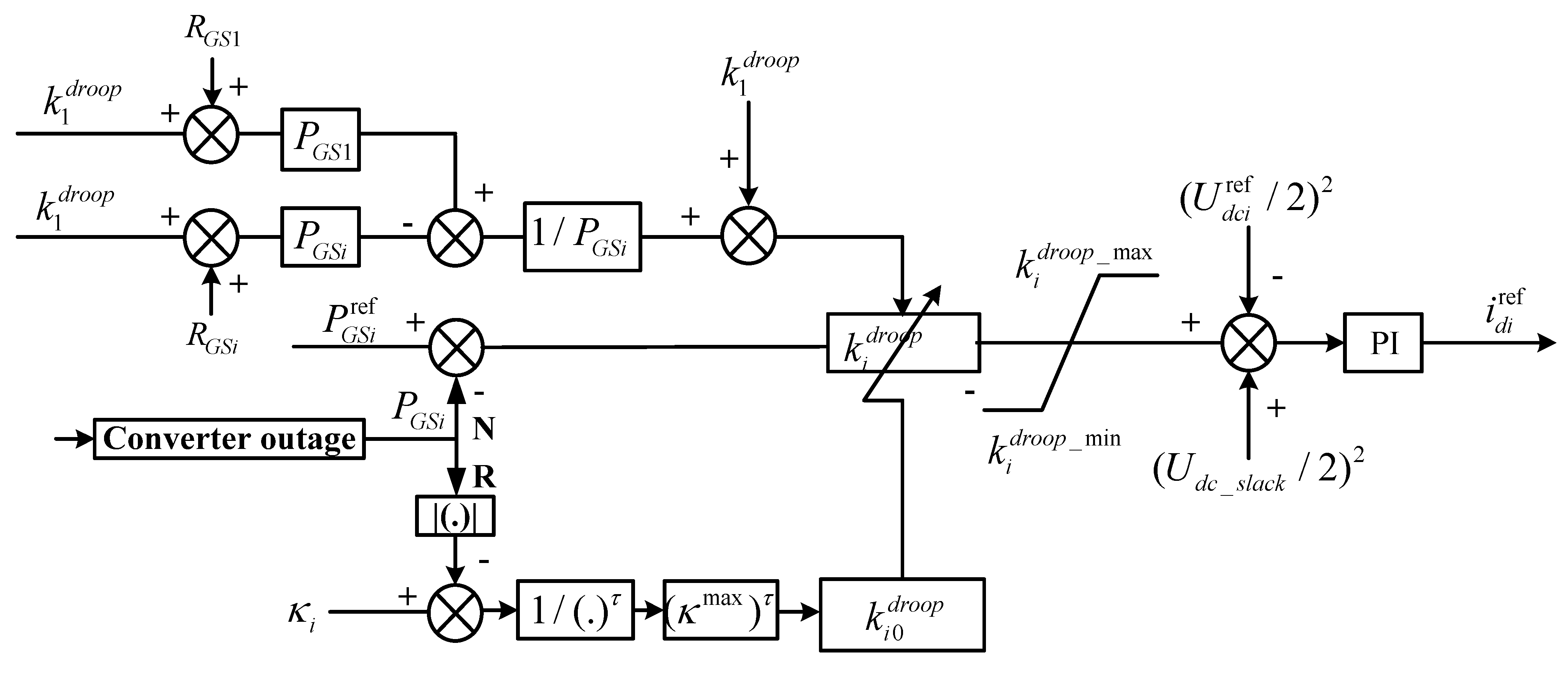
19]. The reason is that station #3 can adjust droop coefficient dynamic according to available headroom of converter capacity, and ensure the appropriate P-U curve, so that reduce copper loss of four-terminal HVDC system.
Table 5. Copper loss as outage of VSC4.
TypeCapacity RatioDroop Control [19]Proposed Method
Without local loadP3ref/P4ref = 316.7124 MW16.5131 MW
With local loadP3ref/P4ref = 316.6357 MW16.4265 MW
The dynamic response of four-terminal HVDC system following inverter outage is shown in Figure 12. 
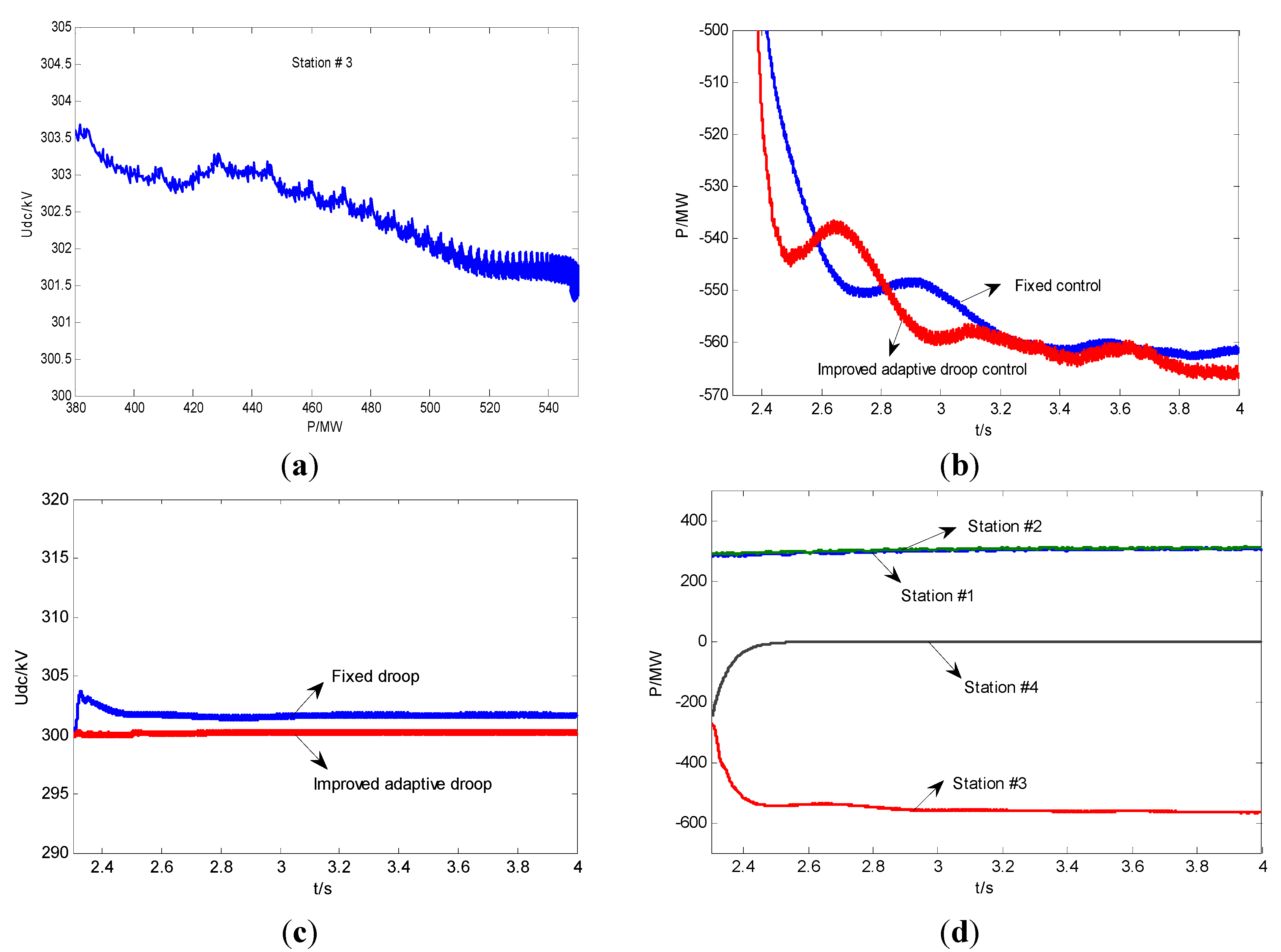
Figure 12a shows that in absence of station #4, slack converter station #3 operating in voltage-power droop control mode increases its power to compensate the power imbalance of the inverter. From Figure 12b, the power sharing of station #3 by improved adaptive droop is larger than that of fixed droop. The reduction of the copper loss is because improved droop control ensures a higher droop value than fixed droop. Variation of DC voltage at converter station #3 is shown in Figure 12c, which is larger than common bus voltage 300 kV with very little overshoot in its transient response for fixed droop control. Therefore, the improved adaptive droop scheme can steady the DC voltage dynamics. In addition, Figure 12d indicates that control strategy of station #3 and #4 can follow the dynamic response effectively. Then HVDC system could reach the post-outage steady-state operating point at 2.4 s. The results in this case are related to system parameters, such as the line resistances. Because the copper loss of HVDC system is square to the line resistances, if line resistances of VSC-HVDC system are much larger, much copper loss would be reduced, and then simulations will be more evident.
Figure 12. Dynamic responses of inverter outage (a) Voltage droop control of station #3; (b) Active power of station #3; (c) DC side voltage of station #3; (d) Active power of all stations.
Energies 08 07100 g012
(2) Rectifier Outage: In order to validate the effectiveness of proposed method, the outage of station #2 is considered, only 300MW is imported into MTDC grid. The results of copper loss of VSC-MTDC without/with local load are shown in Table 6. As we can see, if P3ref/P4ref = 3.0, improved adaptive droop control can reduce copper loss effectively. The minimum copper loss without/with local load are 4.2794 MW and 4.2481 MW respectively, which are smaller than those using methods in reference [12]. The reduced amounts of copper loss are 0.2748 MW and 0.251 MW respectively in this case.
Table 6. Copper loss of station #2.
TypeCapacity RatioDroop Control [12]Proposed Method
Without local loadP3ref/P4ref = 34.5542 MW4.2794 MW
With local loadP3ref/P4ref = 34.4991 MW4.2481 MW
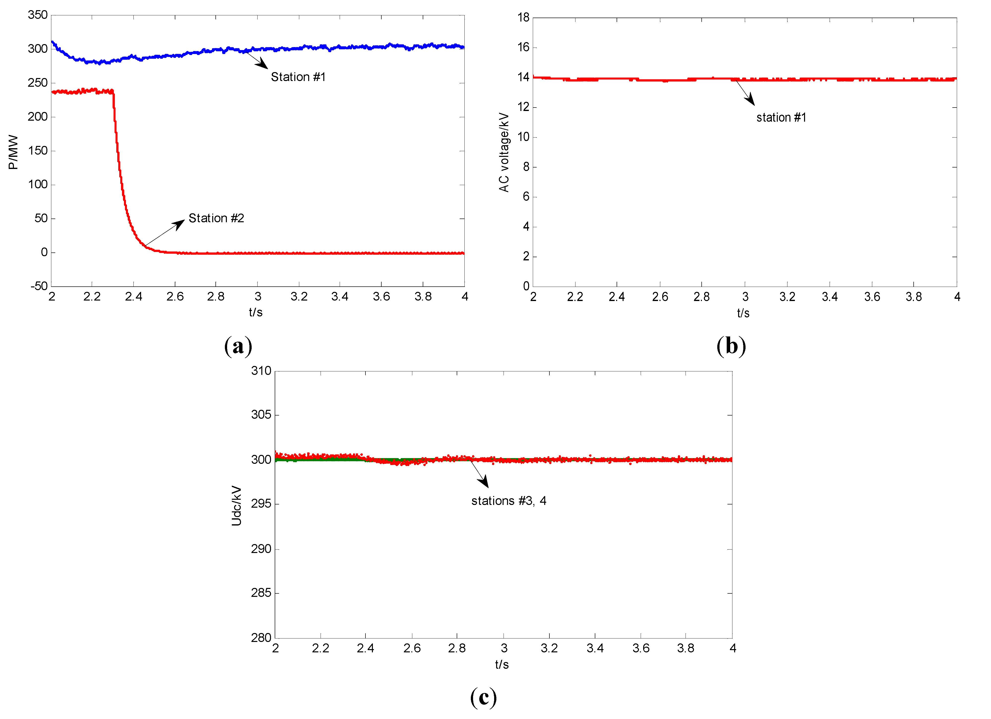
The outage of station #2 appears at 2.3 s, and dynamic response of VSC-MTDC system with fixed droop and improved adaptive droop following the contingency are shown in Figure 13. It is to be noted from Figure 13a that control strategy of station #1 and #2 can follow the power dynamics. In addition, it can be seen from Figure 13b,c that the AC voltage of station #1 can stable operate at 13.8 kV, and it has no effect on DC voltage of VSC inverter side (station #3 and 4) under condition following station #2 outage.
Figure 13. Dynamic response of rectifier outage (a) Active power of station # 1 and 2; (b) DC side voltage of station # 3 and 4; (c) AC side voltage of station # 1.
Energies 08 07100 g013

5.4. Converter Short Circuit of VSC-MTDC

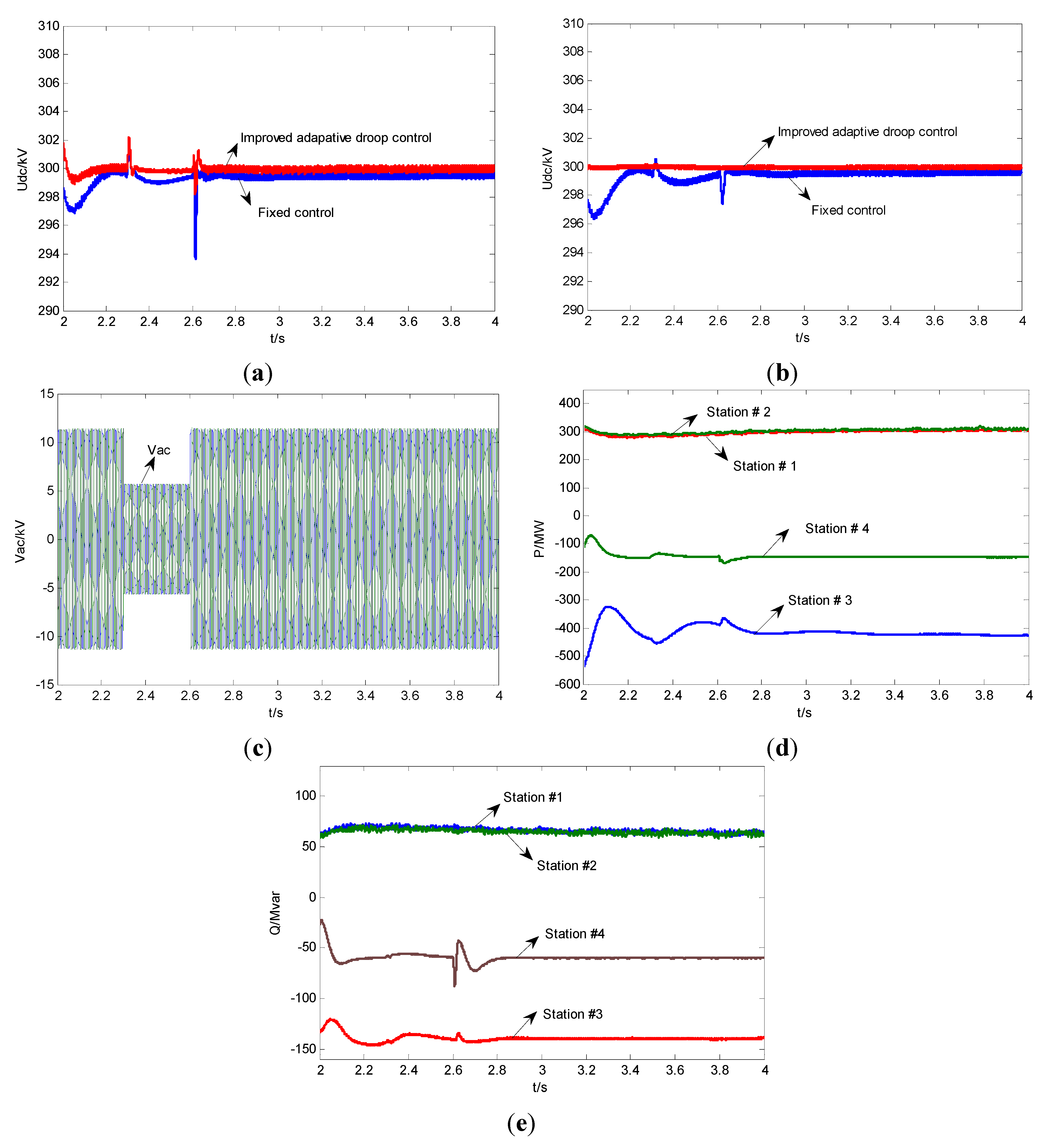
In this section, the performance of the fixed droop and improved adaptive droop control is compared. If a short-circuit fault is detected in AC side close to points of common coupling (PCC), the PCC voltage will be reduced, which in turn affects voltages and currents of ac transmission grid close to PCC. To prevent destructive overcurrent, then distance protection would be actuated at this time. In this case, a three-phase short-circuit fault is introduced at 2.3 s on station #4 with a duration of 300 ms. If the short-circuit fault is detected, the AC side voltage of station #4 decreased from 13.8 kV to 7.0 kV. Dynamic responses of MTDC grid with fixed droop following the contingency are shown in Figure 14. During the disturbance, as shown in Figure 14a,b, DC voltage of station #4 decreased to 298 kV from 300 kV as using the improved droop control while the ones decreased to 293 kV from 300 kV as using fixed droop control method. Therefore, overshoot amount of improved droop control is less than the ones of fixed droop control. Since AC voltage of wind farm was controlled at constant value, its power output about 600 MW injected into VSC-MTDC network remained unchanged. In addition, improved droop control can hold DC voltage of station #3 at 300 kV while fixed droop control cannot realize this objective. The reason is that common DC voltage and available headroom of converter are considered as designing the control strategy of HVDC grid, and the proposed method could improve the stable operation of converter. From Figure 14d,e, it can be seen that the control strategy of station #3 and #4 can follow the active/reactive power dynamic response, and there is small variation for power when improved droop control is employed.
Therefore, the improved droop control method can reduce the copper loss of system effectively, and improved stable operational performances under the condition of inverter outage, rectifier outage and a short-circuit fault of converter, and decrease dc voltage fluctuation and dc power oscillation caused by AC side fault of VSC-HVDC system. Therefore, the improved droop control scheme leads to desirable system performance.
Figure 14. Dynamic response of short-circuit fault. (a) DC voltage of station # 4; (b) DC voltage of station # 3;(c) AC side voltage of station # 4; (d) Active power of VSC-MTDC; (e) Reactive power of VSC-MTDC.
Energies 08 07100 g014

6. Conclusions

With the development of large capacity and long distance HVDC transmission lines, the copper loss of the whole system is considerable. Therefore, the paper provides a discussion based on optimal power sharing on MTDC grids interconnecting large-scale offshore wind farms with ac mainland grids. The control strategies are proposed to reduce the copper loss of the DC transmission line.
This paper has proposed a calculation framework of the variable power-voltage droop coefficients either considering local load or not. Any inverter converter of MTDC grid can be chosen as a benchmark converter and a fixed droop control is employed. The adaptive droop coefficients of other converters are obtained by power difference between other converters and the benchmark one, the optimal power sharing of MTDC grid is realized. Compared with the fixed droop control method, the control strategy is able to reduce copper loss of MTDC grid more effectively under the condition of normal operation and following an outage of converter.
On the basis of optimal power sharing, available headroom of each converter station is considered in case of converter outage, and then the adaptive improved droop control is proposed to improve stable operation as well as reducing the copper loss of HVDC system. Transient simulations are implemented on a four-terminal MTDC grids integrated with two large capacity wind farms. The results for outages of rectifier and inverter as well as short circuit fault under three different scenarios are presented, and steady-state operating points of post-contingency are deduced in detail.

Acknowledgments

The authors acknowledge the support of projects granted by National Natural Science Foundation of China (Grant No. 51377068).

Author Contributions

The methodology followed during investigation is discussed by all authors. Simulations in PSACD/EMTDC were carried out by Xiaohong Ran and the writing of manscript was done by Xiaohong Ran, Shihong Miao provided some ideas on the paper, Yingjie Wu checked the results.

Conflicts of Interest

The authors declare no conflict of interest.

References

  1. ABB Group. It’s Time to Connect—Technical Description of HVDC Light Technology. 2012. Available online: http://www.abb.com/industries/ (accessed on 28 April 2015).
  2. Liu, Y.; Chen, Z. A flexible power control method of VSC-HVDC link for the enhancement of effective short-circuit ratio in a hybrid multi-infeed HVDC system. IEEE Trans. Power Syst. 2013, 28, 1568–1581. [Google Scholar] [CrossRef]
  3. Flourentzou, N.; Agelidis, V.G.; Demetriades, G.D. VSC-based HVDC power transmission systems: An overview. IEEE Trans. Power Electron. 2009, 24, 592–602. [Google Scholar] [CrossRef]
  4. Cole, S.; Beerten, J.; Belmans, R. Generalized dynamic VSC MTDC model for power system stability studies. IEEE Trans. Power Syst. 2010, 25, 1655–1662. [Google Scholar] [CrossRef]
  5. Tang, L.; Ooi, B. Locating and isolating DC faults in multi-terminal DC systems. IEEE Trans. Power Del. 2007, 22, 1877–1884. [Google Scholar] [CrossRef]
  6. Ludois, D.; Venkataramanan, G. An examination of AC/HVDC power circuits for interconnecting bulk wind generation with the electric grid. Energies 2010, 3, 1263–1289. [Google Scholar] [CrossRef]
  7. Pinto, R.T.; Rodrigues, S.F.; Wiggelinkhuizen, E.; Scherrer, R.; Bauer, P.; Pierik, J. Operation and power flow control of multi-terminal DC networks for grid integration of offshore wind farms using genetic algorithms. Energies 2013, 6, 1–26. [Google Scholar] [CrossRef]
  8. Chen, X.; Sun, H.S.; Wen, J.Y.; Lee, W.; Yuan, X.; Li, N.; Yao, L. Integrating wind farm to the grid using hybrid multi-terminal HVDC technology. IEEE Trans. Ind. Appl. 2011, 47, 965–972. [Google Scholar] [CrossRef]
  9. Silva, B.; Moreira, C.L.; Leite, H.; Lopes, J.A.P. Control strategies for AC fault ride through in multi-terminal HVDC grids. IEEE Trans. Power Del. 2014, 29, 395–405. [Google Scholar] [CrossRef]
  10. Beerten, J.; Cole, S.; Belmans, R. Generalized steady-state VSC MTDC model for sequential AC/DC power flow algorithms. IEEE Trans. Power Syst. 2012, 27, 821–829. [Google Scholar] [CrossRef] [Green Version]
  11. Nakajima, T.; Irokawa, S. A control system for HVDC transmission by voltage sourced converter. In Proceedings of the IEEE Power Engineering Society Summer Meeting, Edmonton, AB, Canada, 18–22 July 1999; pp. 1113–1119.
  12. Haileselassie, T.M.; Uhlen, K. Impact of DC line voltage drops on power flow of MTDC using droop control. IEEE Trans. Power Syst. 2012, 27, 1441–1449. [Google Scholar] [CrossRef]
  13. Yao, L.; Xu, L.; Bazargan, M.; Critchley, R. Multi-terminal HVDC grid for network interconnection and renewable energy integration. In Proceedings of the 43rd International Conference on Large High Voltage Electric Systems, CIGRE, Paris, France, 22–27 August 2010.
  14. Cao, J.; Du, W.; Wang, H.; Bu, S. Minimization of transmission loss in meshed AC/DC grids with VSC-MTDC networks. IEEE Trans. Power Syst. 2013, 28, 3047–3055. [Google Scholar] [CrossRef]
  15. Lie, X.; Williams, B.W.; Yao, L. Multi-terminal dc transmission systems for connecting large offshore wind farms. In Proceedings of the IEEE Power and Energy Society General Meeting—Conversion and Delivery of Electrical Energy in the 21st Century, Pittsburgh, PA, USA, 20–24 July 2008; pp. 1–7.
  16. Shu, Z.; Jun, L.; Ekanayake, J.B.; Jenkins, N. Control of multi-terminal vsc-hvdc transmission system for offshore wind power generation. In Proceedings of the 44th International Universities Power Engineering Conference (UPEC), Glasgow, Scotland, 1–4 September 2009; pp. 1–5.
  17. Lu, W.; Ooi, B.T. Multi-terminal HVDC as enabling technology of premium quality power park. IEEE Power Eng. Soc. Winter Meet. 2002, 2, 719–724. [Google Scholar]
  18. Rouzbehi, K.; Miranian, A.; Luna, A.; Rodriguez, P. DC voltage control and power sharing in multi terminal DC grids based on optimal DC power flow and voltage-droop strategy. IEEE J. Emerg. Sel. Top. Power Electron. 2014, 2, 1171–1179. [Google Scholar] [CrossRef]
  19. Chaudhuri, N.R.; Chaudhuri, B. Adaptive droop control for effective power sharing in multi-terminal DC (MTDC) grids. IEEE Trans. Power Syst. 2013, 28, 21–29. [Google Scholar] [CrossRef]
  20. Teodorescu, R.; Blaabjerg, F.; Pedersen, J.K.; Gengelci, E.; Enjeti, P.N. Multilevel inverter by cascading industrial VSI. IEEE Trans. Ind. Electron. 2002, 49, 832–838. [Google Scholar] [CrossRef]
  21. Su, C.W.; Jeong, I.W.; Wen, J.; Smedley, K. Drive the PMSM motor using hexagram converter. In Proceeding of the 23rd Annual IEEE Applied Power Electronics Conference Exposition, Austin, TX, USA, 24–28 February 2008; pp. 1803–1808.
  22. Guerrero, J.M.; García de Vicuña, L.; Matas, J.; Castilla, M.; Miret, J. Output impedance design of parallel-connected UPS inverters with wireless load-sharing control. IEEE Trans. Ind. Electron. 2005, 52, 1126–1135. [Google Scholar] [CrossRef]
  23. Guo, C.; Zhao, C. Supply of an entirely passive AC network through a double-infeed HVDC system. IEEE Trans. Power Electron. 2010, 24, 2835–2841. [Google Scholar]
  24. Abdel-Khalik, A.S.; Massoud, A.M.; Elserougi, A.A.; Ahmed, S. Optimum power transmission-based droop control design for multi-terminal HVDC of offshore wind farms. IEEE Trans. Power Syst. 2013, 28, 3401–3409. [Google Scholar] [CrossRef]

