1. Introduction
A multi-evaporator system is an air-conditioning system configuration where there is one outdoor condensing unit and multiple indoor units, in which the system has the ability to control the amount of refrigerant flowing to the multiple indoor units, enabling the use of many evaporators of differing capacities and configurations connected to a single condensing unit. Many applications require a multi-evaporator to achieve satisfactory conditions on temperature and humidity. A multi-evaporator cooling systems is an innovative distributed cooling system designed to eliminate the use of central chillers and boilers in large installations, which provides individualized control and simultaneous cooling in different zones. Nowadays, a high demand of multi-room air-conditioning services for common households and medium and large-sized building make the multi-evaporators very attractive and significant systems for today’s market.
The increasing development of multi-evaporator cooling systems comes along with a growing competitive environment, which implies the need for operating costs’ reduction and improvement process performance for large-scale control systems. The use of multiple evaporators creates a new set of control challenges, since the dynamics of the evaporators are tightly coupled to each other and could imply large and spatially-distributed devices that involve numerous sensors and actuators, increasing the complexity of control systems, since this implies that the acquisition and actuation activities have to be distributed over different nodes, where the control loops are closed through a networked control system (NCS). At present, few studies in the literature include control strategies for multi-evaporator air-conditioning systems and fewer still where control is performed through a wireless networked control system (WNCS) [
1]. Unfortunately, for multi-evaporator systems, it is difficult to develop reasonably accurate mathematical models with reliably-estimated parameters; these systems have many different characteristics in control engineering, and it is extremely difficult to obtain an exact mathematical model. One of the main features is that the operating point varies usually with the disturbances, such as outdoor temperature (or weather conditions) and thermal loads. For ventilating and air-conditioning systems, PID and fuzzy controllers have been by far the most common control strategies as the complexity of the control problem increased [
2,
3,
4,
5]; however, these control strategies have not been extensively studied, where the control loops are closed through WNCS. In [
6], the application of a fuzzy technique for the output prediction of the evaporator in a waste heat recovery system was shown, reducing significantly the computation time required; on the other hand, we argue that their proposed model has the potential to be used in real-time control applications. A simulation of a conceptual office building with six floors, where each one is divided into six conditioned thermal zones with TRNSYS software, was made by [
7]; the authors propose an optimal control strategy based on an adaptive predictive model and recursive least squares estimation technique; the results that they achieve indicate the reduction of energy consumption with the combined air-conditioning system proposed. Furthermore, the work in [
8] proposes as a solution for ventilation problems in variable refrigerant flow (VRF) systems, a VRF unit and outdoor air (OA) processing unit combined air conditioning system, using the same simulation scenario of six floors divided into 25 air-conditioned zones; they use the ready-made multi-zone building model provided by TRNSYS, and the results obtained by them show that all of the zones of the combined system proposed could maintain their specific set-points within a small error after the control is stabilized, regardless of the set-points being the same or different. For this purpose, a fuzzy control system [
9,
10] is used here to control a set of evaporators. In this fuzzy control, the optimal operations model is considered as the master system, which provides the actions needed to achieve optimum temperature and relative humidity in each room or zone to control. The advantages of this concept are that the optimization can easily be performed for a simplified model and the controller can be designed, such that the real evaporator is synchronized with the fuzzy controller, in spite of bounded unknown dynamics and perturbations. Furthermore, the dynamic conditions are similar in each of the control rooms or areas; only the fuzzy control system must be optimized, and it will respond in a decentralized way to each of the evaporators.
Nowadays, the vision of computer systems that are present everywhere requires a change in the model of the integration in our environment; thanks to these demands, different fields of research, including wireless sensor and actuator networks (WSAN) [
11], have been launched. These networks are increasingly attractive for the monitoring and control of environmental variables; this is due to the application fields of this technology, which are many and of great importance. In order to develop the wireless control network of multi-evaporator systems, in this paper, we address first system integration.
In order to develop the wireless control network of multi-evaporator systems, in this paper, we address first a general architecture of WSAN, consisting of multiple control loops closed through a wireless communication network, as well as integrating a topology, optimal static routing, compensation-based control algorithms for WSAN that exhibit packet dropouts, an aperiodic tasking model for the nodes, an event-triggered sampling scheme for avoid network congestion and integrating an optimal fuzzy control evaporator operations model, topology, routing, sensors and actuators nodes. This architecture proposal allows great scalability, the easy addition of new nodes to cover more area, avoidance of packet loss due to the power of transmit information, as well as adding new evaporators with the same master fuzzy controller or even with multiple masters. The second important aspect of this work is to analyze the end-to-end schedulability of real-time flows over the WSAN, including real-time features of each node, such as the worst-case execution tasks, the temporary effect of the scheduler, the deadline on tasks, the temporary effect of tasks with precedence relationships between their executions, release jitter, among others; it comes to verify the worst-case, message arrival from the smart sensor to the smart actuator, as a necessary, but not sufficient deterministic condition. In this sense, the main interest is to maintain the stability of the WSAN, preserving the scalability, flexibility and cost effectiveness of the used WSAN technology. The IEEE 802.15.4 protocol [
12] with unslotted CA/CSMA mode really is a great alternative to keep these considerations; however, the challenge is to keep the network in unsaturated conditions, decreasing the probability of packet loss; this condition is likely to be achieved by implementing compensation-based control and actuator algorithms, an aperiodic tasking model for the nodes and an event-triggered sampling scheme and a tree topology with an optimal static routing and a simple and easy clock synchronization in the 802.15.4 wireless network, by sending the synchronization messages with a random offset avoiding the nodes’ transmissions at the same time, which prevents messages collisions.
The outline of this paper is as follows.
Section 2 presents an overview of related works, such as other performance and comparative studies. In
Section 3, a detailed design of the architecture, with different constituent elements, is presented.
Section 4 discusses and analyzes end-to-end delay for the real-time flows in the network based on IEEE 802.15.4. In
Section 5, an implemented experimental case is presented over the developed architecture. Validation, results and discussions of the simulation are carried out in
Section 6, and finally,
Section 7 concludes this study.
2. Related Works
This work integrates several aspects, like the control of a set of multi-evaporators that use a master-slave fuzzy control system, wireless network protocols, end-to-end real-time analysis and design methodologies. To meet these requirements, the main focus in this research is the use of the IEEE 802.15.4 protocol for controlling the compliance of the real-time characteristics of a multi-evaporator system decentralized and located in large areas. In this section, we provide a discussion of the related literature.
The process industries are starting to adopt multi-hop and multi-channel wireless control networks (WCNS) for process control applications, which require reliable and secure communications. To fully meet the real-time requirements for a control system, there is a critical need for fast end-to-end delay analysis; because delays affect the performance of NCS, their applications have end-to-end real-time constraints. In order to overcome this inherent difficulty, problem restrictions and heuristics must be used. A common approach is to statically allocate application tasks at system nodes and locally utilize either a well-known scheduling algorithm, like rate monotonic (RM) or earliest deadline first (EDF) [
13,
14].
Several studies have been developed to analyze end-to-end delay [
15] and end-to-end scheduling that use task scheduling algorithms, like RM, EDF and MAC protocols based on TDMA [
16,
17,
18,
19]. These last works use buffers to store messages in network nodes and employ a scheduling method to deliver messages. They are based on finding the maximum response time of all messages. Many of these efforts are focused on scheduling messages and the sampling time assignment for the sensors/actuators and controllers interconnected by the wireless networks; however, these do not have a method that includes a formal analysis of integrating the dynamics of the plant, network topology, scheduling, routing, transmission errors and control. One of the main differences between these papers and our work is that we do not consider message storage in buffers, because the size of messages in industrial applications is small compared to the amount of data supported by each message in Wireless sensor networking technology based on the Highway Addressable Remote Transducer Protocol (WirelessHART) (maximum payload in physical layer protocol data unit (PDU) of 127 bytes). Then, it is assumed that each message is sent within the space reserved for a node in the TDMA network. This proposal differs from previous ones in that it is not necessary to perform the scheduling of messages in buffers; therefore, we assume that the delay introduced by the network is constant and equal to the maximum possible, which is the period to repeat the slots in the WirelessHART protocol [
20].
In [
21] proposes a mathematical framework for modeling and analyzing multi-hop control networks designed for systems consisting of multiple control loops closed over a multi-hop (wireless) communication network. The authors make a separation of control, topology, routing and scheduling messages, proposing a formal model for analyzing the robustness of multi-hop control networks, where data are exchanged through a multi-hop communication network subject to disruptions. However, the formal analysis in this paper is applicable to linear systems, and as is known for many multi-zone control, it is difficult to develop reasonably accurate mathematical models with reliably-estimated parameters where uncertainties are due to the limit process knowledge, nonlinearities, unmodeled dynamics, unknown internal and external noises, environmental influences and time-varying parameters.
The authors of [
22] have mapped the transmission scheduling of real-time data flows between sensors and have presented an end-to-end analysis to determine the schedulability of real-time message flow using WirelessHART. This work performs an important study on the scheduling of messages; however, from the point of view of control systems, a complete analysis that takes into account the temporary drifts that can affect the controller and direct action on the plant does not exist, so the study does not focus directly on the requirements of the control system.
In [
16], the multi-hop network that controls a simulation environment facilitating the simulation of computer nodes and communication networks that interact with the continuous-time dynamics of the real world is presented. In that work, and in the ours, the use of a formal method of analysis is reported; however, no analysis of end-to-end messages is reported, also excluding the WirelessHART protocol in the tool presented.
We present in [
13] a minimal set of components for the design a WSAN and its representation in colored Petri nets, allowing one to verify behavioral properties and system structures; however, ZigBee modeling is not fully enclosed in colored Petri nets; the control system is not modeled, which does not allow a complete check of the control system, including communication, the controller and plant as a distributed system.
Finally, in this work, we present an architecture of NCS, consisting of multiple control loops closed over a multi-hop communication network and integrating an optimal multi-evaporator operations model, topology, routing, sensors and actuators nodes, and we analyze the end-to-end schedulability of real-time flows on wireless sensor and actuators networks (WSAN), as well as present an environment that facilities the simulation of computer nodes submitted to the architecture proposed.
3. Description of the Building Fuzzy Control
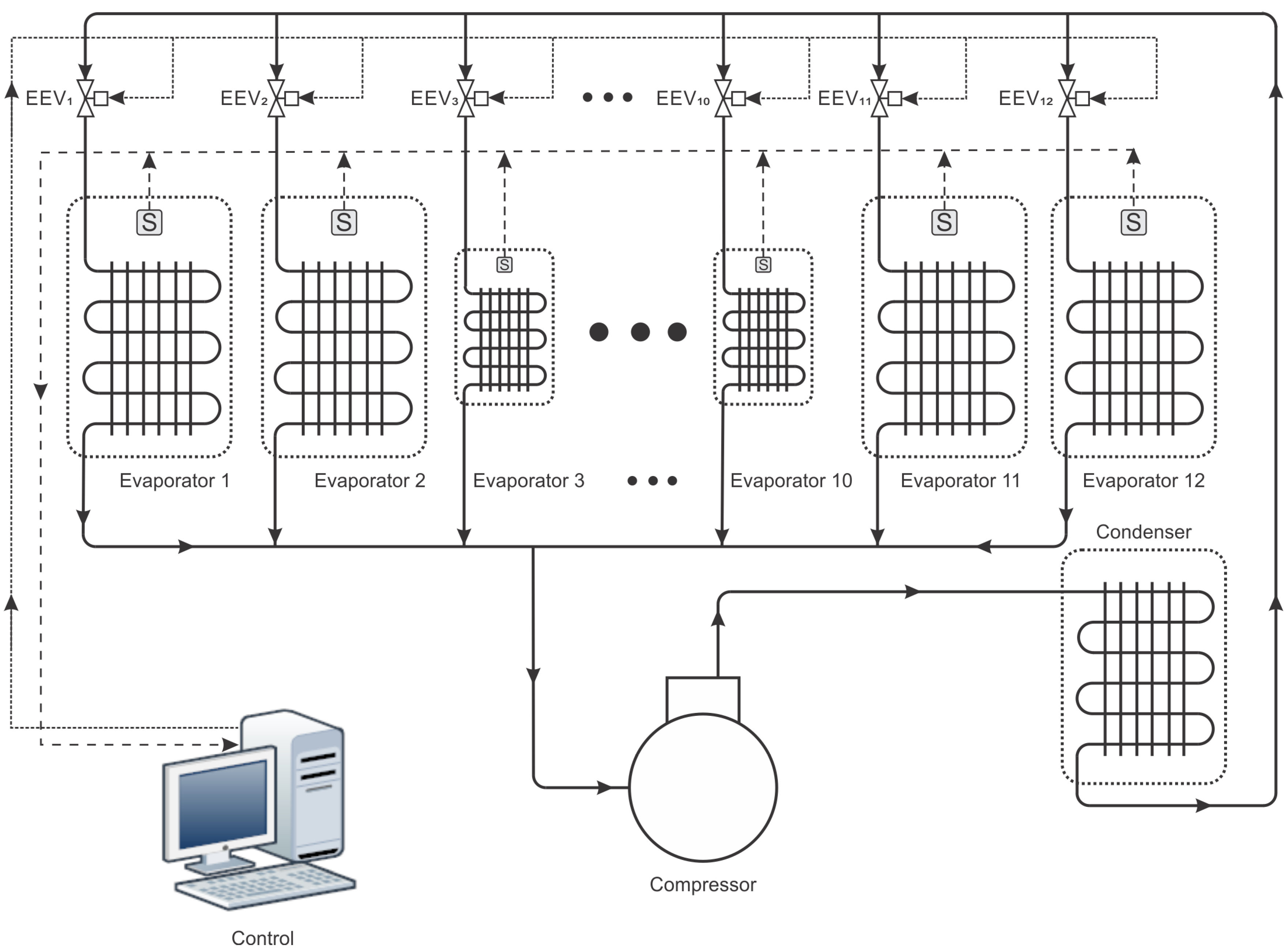
Operating rooms in hospitals require optimal facilities to secure the highly demanding indoor environmental conditions for patients and medical personnel. In this section, we provide a description of the building fuzzy control implemented. The buildings structure has six floors in total, where only one floor of the building is divided into 12 conditioned thermal zones corresponding to six hospital operating rooms, intensive care units, laboratories, drug storage rooms, etc., which require installations with an efficient air-conditioning system for tropical environments to secure the highly demanding indoor environmental conditions for patients and medical personnel. The required indoors conditions, such as temperature and humidity, are the most important control variables, according to safety standards in tropical countries (e.g., Colombia, Costa Rica, Mexico, Peru, among others). For instance, for the sanitary conditions of hospitals and similar establishments according to the Health Ministry of the Republic of Colombia, the minimum and maximum temperature is between 20 °C and 24 °C, respectively, and for the relative humidity (RH) from RH=30% to 50%.
The multi-zone air-conditioning system with temperature and relative humidity control as a multi-input and multi-output closed loop system is shown in
Figure 1. All loops are controlled by the same smart controller that implements a fuzzy logic control for all multi-evaporators and exhaust fan systems, being executed in the CPU controller; fuzzy logic does not implement any derivative action, so it is not required to keep the previous states, and calculating the control action is executed in an instant of time.
Two sets of sensor inputs are electronic temperature and humidity sensors, and two outputs from the controller are distributed to regulate operating rooms and other areas to control; electronic expansion valves (EEV) and an exhaust fan are mounted in each room. For control purposes, a simplified model of temperature and humidity for each room can be used; this thermal system can be a single-zone space enclosed by an envelope, exposed to certain outdoor conditions, and the short-term response of a control system to some disturbance can often be analyzed by considering the room air volume. The room air capacity transfer function can be obtained by applying the principle of energy balance, as shown in [
23,
24]; thus, a simplified model for a room’s temperature is as follows:
where Θ (°) is the room air temperature,
(°) is the supply air temperature (in the humidifier),
(°CW
-1)is the plant gain of room temperature dynamics,
(min) is the time constant of room temperature dynamics and
(min) is the dead-time of room temperature dynamics.
The room humidity model can be derived by applying the principle of mass balance as shown in [
24]; thus, a simplified model for a room’s humidity is as follows:
where
X (kg/kg(DA)) is the indoor absolute humidity and DA means Dry Air,
(kg/kg(DA)) is the absolute humidity of the supply air,
is the plant gain of room humidity dynamics,
min is the time constant of room humidity dynamics and
min is the dead-time of room humidity dynamics. The constant values were obtained relating [
23,
24] with building plans, and experimental measurements are made in “Nuestra Señora del Rosario” Hospital in Cali, Colombia, the aim of which is to show simulations based on actual situations and real conditions.
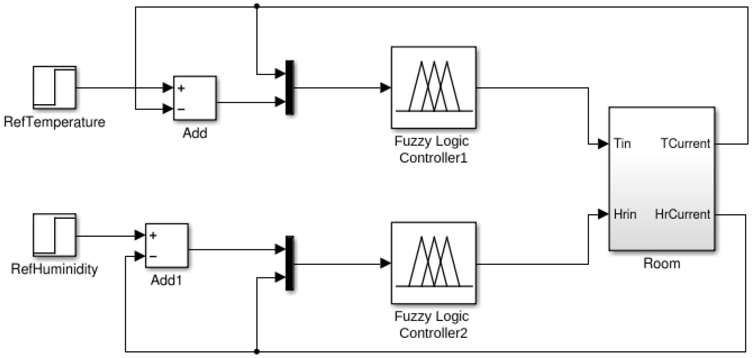
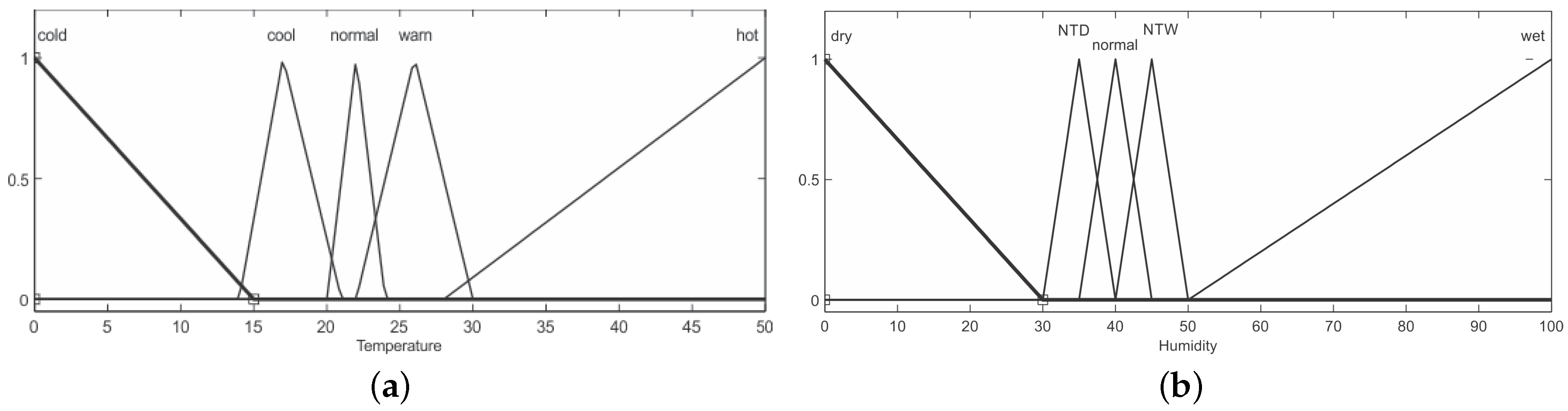
Figure 2 shows a block diagram of the room temperature and humidity control systems using the fuzzy control system. Both temperature error and relative humidity error are quantified according to the memberships in the fuzzy sets as shown in
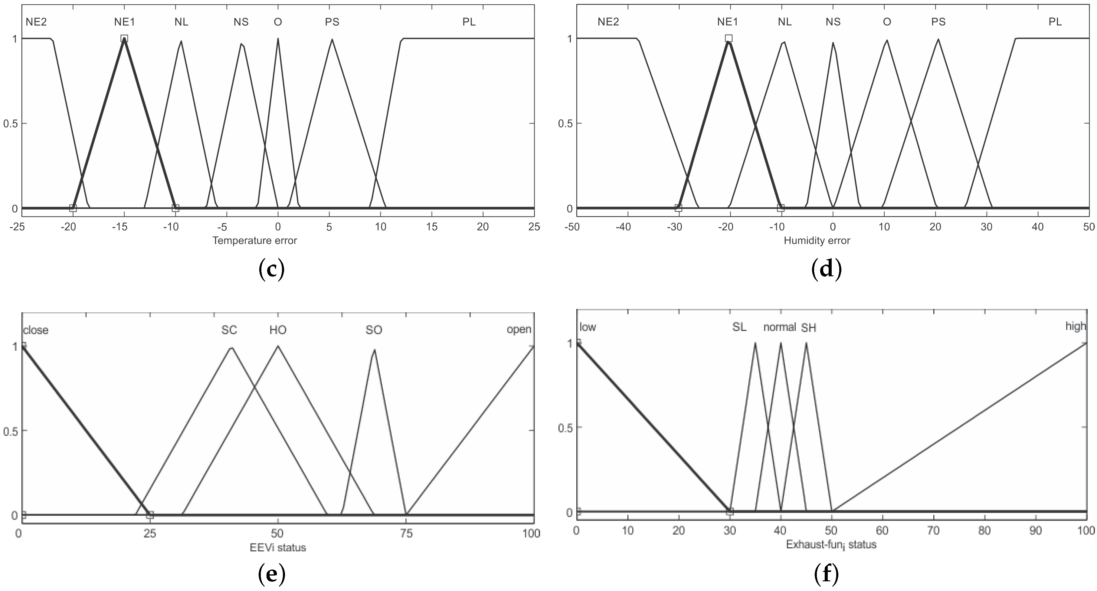
Figure 3a to d.
Figure 3e,f is the rule base EEV and exhaust fan. To implement this process, it uses the following fuzzy sets, which are: NTD (not too dry), NTW (not too wet), O (zero), NS (negative small), NL (negative large), NE1 (Negative Extreme 1), NE2 (Negative Extreme 2), PS (positive small), PL (positive large), SC (semi-closed), SO (semi-open), SL (semi-low) and SH (semi-high).
4. Wireless Sensor and Actuator Network Architecture Systems’ Design
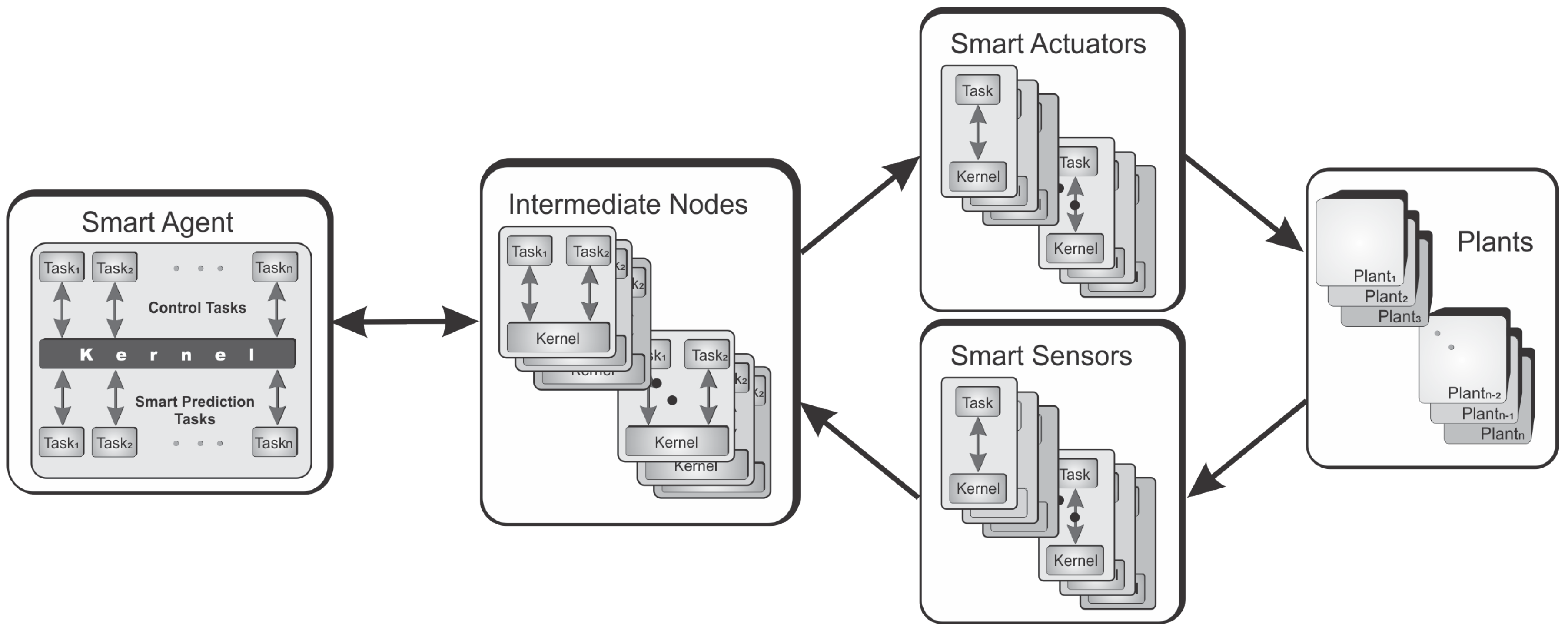
We propose an architecture based on multi-agents, tree topology, the data-flow model for the system nodes, algorithms for the compensation of lost packets for control and actuator nodes, the aperiodic tasking model for the nodes and an event-triggered sampling scheme for the control of the multiple or parallel plants closed through a multi-loop communication network, which is shown in
Figure 4. This architecture design focuses on applications that demand lower bandwidth (less than 250 kbps), with low computational cost requirements and operating in small areas of extension, but includes support for multi-loop control networks; it also allows compliance to end-to-end real-time constraints, facilitating the implementation and simulation of computer nodes, integrating a topology, optimal static routing, sensors and actuators nodes, as well as providing scalability to multiple plants and different control variables, which increases the flow of control loops and also the increase in the nodes, enabling multiple networks to be controlled.
One of the main ideas in this architecture is to use a simple network configuration mode, permitting easy scalability and fast maintenance and operation. The IEEE 802.15.4 in unslotted mode is not exactly the best choice for networked control systems; however, the IEEE 802.15.4 protocol in unslotted mode has a very easy configuration, rapid deployment and highly scalable; it allows including new evaporators, new controllers and new nodes for new statics routing without major redesign commitments, evenly, eliminates evaporators, nodes and routes without without any redesign of the system. The challenge is to maintain real-time constraints with a purely probabilistic network; this is possible, ensuring an unsaturated networks, and achieves the highest probability of the packet transmission network. To achieve the best conditions for a network unsaturated in network control applications, a system of multi-agent nodes, aperiodic tasks and an event-triggered sampling scheme were implemented. However, despite generating better conditions and achieving an unsaturated network, lightweight and flexible compensation algorithms of packet loss should be implemented in the smart agent nodes (controller, sensor and actuator nodes) and, thus, to ensure the best conditions to accomplish the features of a real-time wireless network.
The architecture shown in
Figure 4 is designed in layers, and each one has its own specific role, where the plants are controlled by a master controller system from a smart agent node. Given the distances between the sensors and actuators installed in each plant, the use of intermediate nodes is necessary, in order to deliver the messages to the controller, maintaining the amount of energy used to transmit information and avoid packet loss for this effect. The smart sensors send the measurements to the smart agent node that is responsible for deciding about the data, either predicting a value for control tasks if the data have not arrived at a certain deadline or communicating the data that have arrived to the control tasks and, later, sending the control signal to the respective smart actuator using the wireless network. The communication between smart sensors, smart agent and smart actuators is provided by the IEEE 802.15.4 protocol. The components that integrate the architecture can explained as follows.
4.1. The Smart Sensor Node Model
Smart sensors are usually defined as the combination of a sensor to condition the signal before its transmission to the control network, having embedded algorithms besides a digital interface [
25]. The smart sensor node in the proposed architecture implements an algorithm with a periodic task that is responsible for the sensing of physical variables and its transmission to intermediate nodes or to a smart agent node. A periodic task sampled the sensed values of the variables, with a constant set period; the sampling sequence is described by the set
with
, and
k represents the
k-th sample. However, the transmission to router nodes is determined by an event-triggered scheme, which is used to determine when data should be transmitted based on the error between the current sampled datum and the last transmitted one. The main advantage of the smart sensor use is the reduction of data communication, due to some sensed data being filtered by the embedded algorithm. The idea of the event-triggered scheme is shown in Algorithm 1:
![Energies 09 00142 i001]() |
| Algorithm 1: Smart sensor node algorithm. |
where
is the state of
,
h is a constant set period,
is the last transmitted state of the evaporator,
is the error between the current sample and the last state transmitted and
is the selected threshold for each
of the
; in this way, the event-triggered scheme used allows data transmission when the following condition is met:
The deadlines are fixed according to the application needs.
4.2. The Smart Actuator Node Model
The smart actuator nodes receive control actions from the controller, which can be delivered directly from this or through the intermediate nodes. The smart actuators nodes implement an aperiodic task that receives and executes actions when a data packet reaches the node. If a message is lost, the smart actuator implements a compensation system based on past performance values. A system based on the control values obtained allows greater generality and no dependence of the mathematical model of the plant. The strategy to deal with control packet dropout is using a FIFO queue (F1) for storing previous or past control actions and generating an actuation signal from the FIFO queue when a control packet dropout occurs. F1 is the FIFO queue, with a capacity of a few storage packets, due to the smart actuators being small nodes, with low computing power, so the decision algorithm of a new actuating signal in the presence of lost packets might have low computing capacity, but sufficient for many industrial applications. The computation of predictive values corresponding to time
k is obtained as follows:
where
is the control action to predict according to previous control values,
and
. A predictive control,
, represents a simple scheme of control proportional-derivative (PD), where
m control values are stored in the F1 FIFO queue;
and
are the respective gains of PD; and
T represents the control period. It is possible to know the maximum waiting time for a sample (deadline) by Equations (
10) and (
11), which are presented below (worst-case end-to-end delay of each flow control). The smart actuator node waits for a sample until its respective deadline; if a sample is lost, the predictive algorithm generates an action according to previous control values
,
; the
T and
m control values are stored in the F1 FIFO queue. The simplest case of prediction is a linear extrapolation from the last
m control packets queued in F1. More sophisticated compensation systems can be used; however, in an industrial control system with slow dynamics and control based on WSAN, linear extrapolation is an excellent compensation choice for controlling packet dropout.
4.3. Static Repeater Nodes
The intermediate nodes include support to implement peer-to-peer control networks, where the main idea of these nodes is to include the amount of power used to transmit information and prevent packet loss due to these causes. Each repeater node (R) implements at least two aperiodic tasks to transmit the values to other nodes; however, in most cases, they allow it to be part of multiple paths between the smart sensor to the controller in the smart agent and the controller to the smart actuator, and in this case, they must implement at least two tasks for each route that is involved, which are scheduled by the EDF algorithm and, hence, a minimum real-time kernel that executes real-time tasks running under the EDF scheduler, which must be running on the nodes. The aperiodic tasks represent computations in a distributed system as a collection of tasks with precedence relationships between their executions, avoiding high network traffic and keeping the network under unsaturated conditions.
4.4. Smart Agent Node
The smart agent node is responsible of deciding about the data, either predicting a value for control tasks (control functions) if the data have not arrived at a certain deadline or communicating the data that have arrived at the control tasks and sending the control signal to the respective actuator using the wireless network. In the presence of packet losses, a packet loss compensation scheme is implemented in this node. Several functions and strategies have been developed and have shown great effectiveness [
26,
27,
28,
29]; in this work, we have mainly given higher priority to those strategies that do not include a mathematical model of the plant in the controller. The key feature of this technique is not to design the controller. This allows one to enable compensators when a packet dropout occurs only using the I/O data of the plants and can realize the adaptive or prediction values of packet loss both in a parametric and a structured manner; thus, these methods do not require a plant and/or disturbance model in the controller design. One of the most promising strategies is presented in [
27], which proposes a linear extrapolation based on the derivative actions from the previous control actions. The problem can be proposed as follows:
where
n represents the number of data that is stored on the smart agent node for prediction purposes. In this paper, the delay effect is not considered, mainly because treated plants have a slow dynamic, and the deadline is considered sufficient. The basic idea is that whenever a sensor data packet is lost, the smart agent node will produce an estimate of the sensed value and sends this to the controller. Furthermore, the resource-constrained smart sensor and smart agent node favor simple algorithms that yield small computational overheads. In the case of systems that have an optimum plant controller, the main idea is to predict the state of the plant quickly and easily in the presence of packet loss. Two simple algorithms are presented below:
where the goal is to compute a moving average of the previous
m samples. Alternatively, based on the previous algorithms, this is to assign weights to each previous sample. Different weights can be assigned, as shown in the following equation:
where
is a parameter design that commonly satisfies
.
4.5. Distributed Precedence Relationships between Tasks
The architecture designed in this work uses an unslotted CSMA/CA algorithm as the media access control, which is appropriate for its very easy configuration, rapid deployment and highly scalability, facilitating the implementation of energy-saving strategies. However, the probabilistic nature of this mode is not optimal to fulfill the real-time constraints. The main objective to meet the timing requirements is avoid network congestion, implementing a system of aperiodic tasks, a simple, but efficient event-triggered sampling scheme, a compensatory control and an actuation system. In the case of the compensation system, on the side of the smart agent controller and the smart actuator, it is necessary to determine a deadline as the event allowing the triggering of the algorithms to compensate both the smart agent controller and the smart actuator nodes. The control architecture establishes flows defined for messages, which can be represented as a collection of tasks with precedence relationships between their executions. Each task must be executed in separate nodes and have mutual exclusion. In [
30], an exact schedulability analysis for real-time systems scheduled at run-time with a static priority preemptive dispatcher is presented, which can be extended to WSAN with certain restrictions (release jitter), such as waiting for a message to arrive. The idea is to include in the computed worst-case response time for a task
i the worst-case response times of predecessor tasks located on other nodes and the worst-case communication delay, as the worst-case due to the conditions of multitasking, effects of the scheduler and real-time constraints imposed on each node. The worst-case release jitter of such a task can be computed by knowing the worst-case response times of predecessor tasks located on other nodes, in addition to knowing the worst-case communication delay. In this way,
is the worst-case time task
i can spend waiting to be released after arrival (the release jitter time) and corresponds to:
where
is the set of tasks that directly precede the task
i, where
is the transit time of a message sent from task
k to task
i. In order to know the impact of the unslotted CSMA/CA algorithm, we must compute the
delay, taking into account the maximum values of the parameters that produce the worst-case transmission message between
, and finally,
is the worst-case response time measured from the point at which task
k is released; it can be calculated as follows:
is the worst-case response time measured from the point at which task
i is released;
is the worst-case computation time required by task
i on each release;
is the lower bound on the time between successive arrivals of
i.
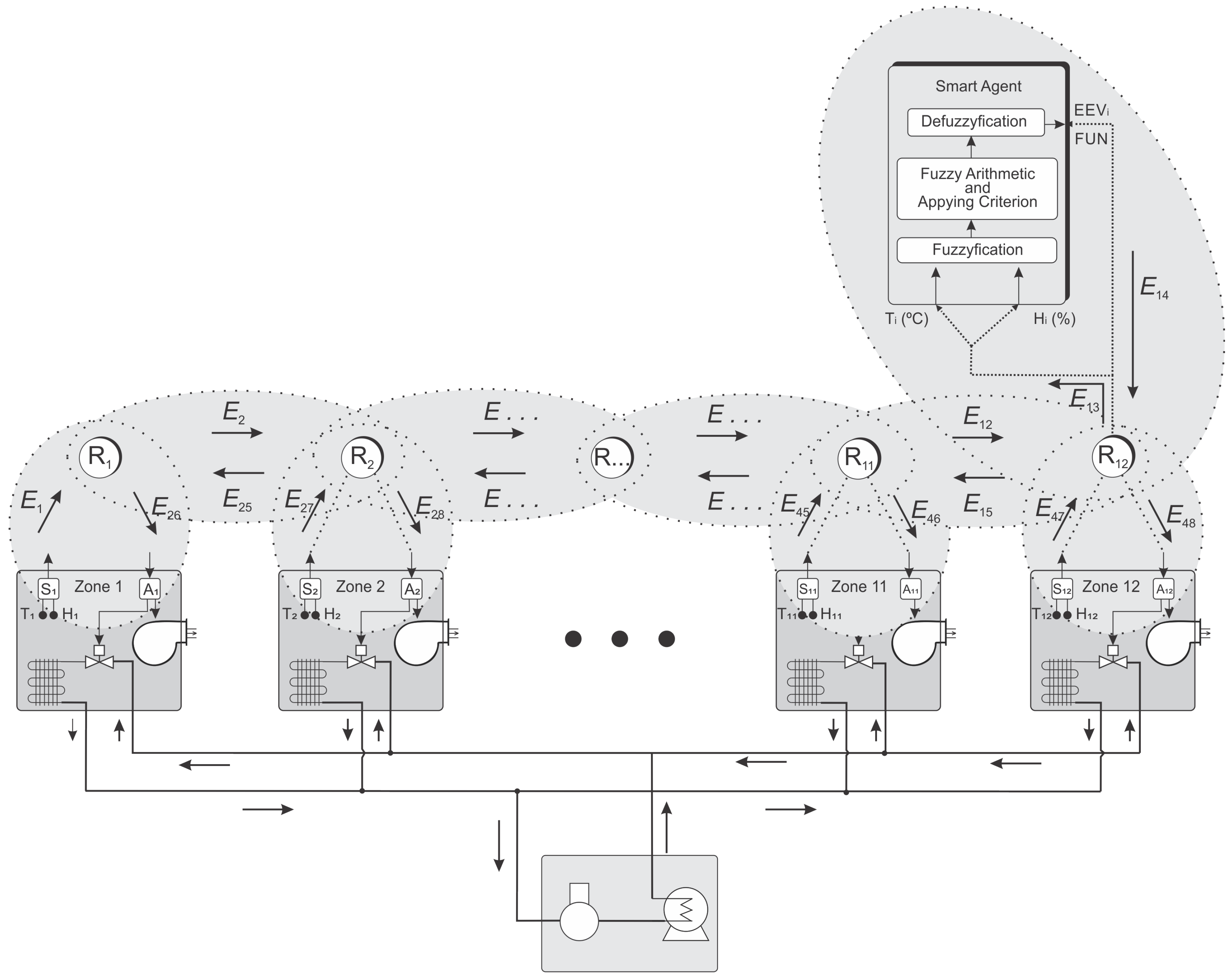
5. Wireless Control Network Architecture for Multi-Evaporator Air-Conditioning Systems
The wireless network embedded control system is shown in
Figure 5, where the plants are the multi-evaporator systems controlled by a unique master fuzzy controller system. Given the distances between the sensors and actuators installed in each room, the use of intermediate nodes is required, in order to deliver the messages to the controller.
The temperature and humidity sensors send the measurements to a smart agent node (SAg) that is responsible for the communication with the controller and sending the control signal to the respective actuator using the wireless network. Whereas a general framework where the tasks to perform the functions within the WSAN, smart sensor (SS), repeater (R), smart agent and smart actuator (SA) have a precedence relationship between them, the control architecture is based on the execution of periodic tasks from the sensor nodes and aperiodic tasks for routing messages once they reach a node. A WSAN is modeled as a graph
G = ((SAg,R,SS,SA);E), which models the radio connectivity of the network, where the node set
represents the network devices, and
E is the set of links between these devices (see
Figure 5). According to the IEEE 802.15.4 protocol, a node cannot send and receive a data packet in the same time, and its transmission is associated with a link, for instance (
,
), where
to
means that
can receive messages transmitted by
; and to reach a node outside its scope, it must pass according to an established route. For the model, the following functions and concepts are defined:
F = {
,
,
,
,
,
,
,
,
,
,
,
} is a set of real-time flows, which need to be end-to-end verified; where each flow
is characterized by:
with
, where
n is the amount of evaporators to be controlled.
is the end-to-end deadline according to the control performance goals.
is a set of end-to-end delays of .
= (); where , and are respectively the worst-case execution time, deadline and period of task for each node of the network, and a set of tasks are scheduled under the EDF policy.
is the worst-case response time for task for each node of the network.
6. Worst-Case End-to-End Delay Flow Control Signals Analysis
This paper proposes a strategy analyzing end-to-end communication in WSAN, taking into account the control architecture presented above, as well as the control system under a formal model. The method presented for end-to-end delay analysis for the real-time flows in a network based one IEEE 802.15.4 is efficient and safe, for the case of a configuration based on unslotted IEEE 802.15.4. In a probabilistic network, as is the unslotted mode, there is no assurance that a message sent from a smart node is received in another smart node; however, in the event that a message reaches its destination, it is possible to determine the worst-case time of its possible arrival at the destination, not only from the point of view of the network, but also integrated with the features of the multi-tasking kernel, scheduler, worst-case release jitter and the worst-case execution time for the tasks on each smart node. Having a good estimate of the time lapsed for each message in each smart node and each task in the worst case, it allows setting the necessary deadlines to enable compensators in the smart agent (controller), smart sensors or smart actuator nodes, in addition to verifying that each closed loop of the multi-loop control meets the real-time constraints of each plant and the entire distributed system. In our WSAN architecture, we chose local EDF policies for scheduling the tasks. The worst-case of the end-to-end analysis is focused one determining if a set of real-time flows is schedulable, if every flow has a worst-case end-to-end delay that is less than or equal to its own deadline, as well as the analysis of scheduling in each node. We include periodic tasks in the smart sensor nodes to analyze the compliance to the deadlines in the nodes and ensure delivery of the message in the tree topology and data-flow model proposed.
The IEEE 802.15.4 protocol implements two types of medium access, without synchronization (non-beacon mode) and synchronization via beacons. In the non-beacon mode, the protocol is a simple CSMA/CA, which facilitates scalability and self-configuration of the network, but it is difficult to calculate the maximum transmission time. We are interested in WSAN performance analysis for real-time applications in non-beacon mode; this mode has a greater scalability, network self-configuration and the least overhead, so it will give us an upper bound on the maximum throughput of the protocol. We consider the processes that generally have slower response dynamics; thereby, if it meets the minimum real-time requirements, the priority is to increase the capabilities of scalability and network self-configuration, facilitating their implementation and development in a wide variety of domains, mainly in scientific and industrial applications.
The CSMA/CA algorithm is based on the node listening to the channel, which will attempt to transmit and detect if any other member node of the network is transmitting; this procedure is performed by the binary exponential backoff algorithm. The slotted CSMA/CA backoff algorithm is based on mainly two variables that correspond to: BE , which is the current backoff exponent, and NB , which is used to count the number of backoffs. The detailed algorithm can be seen in many works [
31,
32,
33,
34,
35,
36,
37]. In our previous work, we performed an analysis of schedulability with strict real-time constraints and the synchronous mode of the 802.15.4 protocol [
13,
20]. Nevertheless, one of our main goals in this work is to provide a strategy for addressing systems that are highly scalable and the network self-configuration, but fulfilling the real-time constraints imposed by the control system. In order to know the impact of the unslotted CSMA-CA algorithm, we compute the end-to-end delay in the worst case; doing that, the unslotted CSMA/CA parameters take their maximum values, which produce the worst-case transmission message between
, which corresponds to the following maximum values:
,
and
[
33,
35]. This also leads us to simplifying the calculation of Equation (
8), allowing one to know the delay impact (
) of the unslotted CSMA/CA algorithm, taking into account their maximum values of parameters that produce the worst-case transmission message between
and, therefore,
, where
is the worst-case transit delay for all messages sent from task
k to task
i. Various researches have described how to calculate the effective and actual data rates of an IEEE 802.15.4 wireless network, permitting the calculation of the transmission time between neighbors, giving a very rough estimate for
[
33,
34,
35], which is approximated to
ms between two neighboring nodes that employ the WiSe mote [
38] for wireless microcontrollers, allowing us to reduce the calculation for each flow of the control loop to:
with
, because each flow starts with the smart sensor node and its corresponding periodic task. Therefore, if the time required to send messages from the smart sensor nodes to the smart actuators nodes, through the routing nodes, smart agent nodes and smart controller nodes, is less than the period available for dispatch within each of the control loops, the system shall comply with all temporal restrictions, so that the end-to-end delay test is necessary to verify the following conditions:
However, verification of these conditions is not sufficient to certify the real-time constraints of a WSAN. The worst-case message transmission of the messages’ flow allows one to set the deadlines in the compensation algorithms. Now, considering the parameters as the worst-case of the computing tasks on the nodes, the path in which messages are propagated in the network topology and Equations (
9) and (
11), We can get the behavior of the deadline against the increase of plants with the same characteristics. In the generic architecture proposed, nodes in the wireless sensor network include a microkernel, which implements an EDF scheduler, computational libraries for readings of ADC and DAC, the IEEE 802.15.4 stack, a minimum communications middleware and the application for calculations of control algorithms. The worst-case execution time (WCET) can be measured by task, from the time that a message is read until it is sent, estimating the worst case that can be chosen. In our previous works [
38,
39,
40], a description has also been made of the hardware and software implemented, and a complete calculation of the computing time has been made, taking into account the aspects mentioned above, and used in the same research works, which allows us to estimate the computation time using the WiSe mote as [
38] in the worst-case, as 0.03 s by task and 0.08 s in the smart agent node, similarly by task.
7. Evaluation, Results and Discussion
In this work, we are interested in the performance analysis of WSANs for the development of real-time control applications in non-beacon mode (unslotted IEEE 802.15.4), as is the case of multi-evaporator systems; this mode has a greater scalability, self-configuration of the network and the least overhead, but it must be implemented in processes that require slow dynamics and, thereby, ensuring minimal real-time features. The priority is to increase the capabilities of the scalability and the self-configuration of the network, facilitating their implementation, maintenance and development. In the context of this paper, an extension is presented to control several evaporator systems using a standard protocol for wireless networked control systems, which are widely used in industrial applications. We considered 12 closed control loops over a wireless communication network, one for each of the six operating rooms and six more for intensive care units, laboratories, drug storage rooms, among others. The simulation time considered for the performance analysis of the network was five hours (300 min), taking into account that this time is enough to carry out full surgical procedures. In subsequent analyses, the time (300 min) used for the simulation also allows one to appreciate the behavior of the control and the entire system as a whole against perturbations.
Each of the values used in the simulation are based on the WiSe mote [
38], which was previously developed in previous works, and it is described as follows: the systems master module is the processor, which is built around a 32-bit ARM7TDMI-S CPU with real-time emulation and embedded trace support. The actual microcontroller used is the LPC2148, which, with its 512 K of high-speed flash memory and 32 K of SRAM data memory, is capable of running a POSIX real-time kernel and many kinds of different routing algorithms. It also contains many interesting features, including: a low-power real-time clock (RTC) with independent power and a 32-kHz clock input; a 60-MHz maximum CPU clock available from programmable on-chip phase-locked loop (PLL); multiple serial interfaces, including two UARTs; two fast I2C-bus (400 kbit/s); serial peripheral interface (SPI) and synchronous serial port (SSP) with buffering and variable data length capabilities; the on-chip integrated oscillator operates with an external crystal from 1 MHz to 25 MHz and power saving modes that include idle and power-down. The communication module is based on the IEEE 802.15.4-compliant RF transceiver, and the WiSe communication module contains the CC2420.
The topology of network is shown in the
Figure 4, in which the temporary restrictions in each closed control loop of each room are different and must be verified and validated. An analysis of end-to-end delay is made in the previous section, and the TrueTime tools were used to simulate and analyze each of the closed control loops. TrueTime is a MATLAB/Simulink-based simulation tool that has been developed at Lund University [
41]. This tool provides models of multi-tasking real-time kernels and networks that can be used in simulation models for networked embedded control systems. The IEEE 802.15.4 protocol has been implemented in MATLAB TrueTime toolbox. The functions in C++ and MATLAB are provided, which also have been modified, adding new functionalities to fully simulate the IEEE 802.15.4 protocol and to provide the support analysis for the end-to-end communication over TrueTime toolbox Version 2.0 of MATLAB, which is very fine and can simulate real-time systems, taking into account issues such as jitter, deadlines, WCET, networks and their responses over time, multi-tasking, kernels, among others.
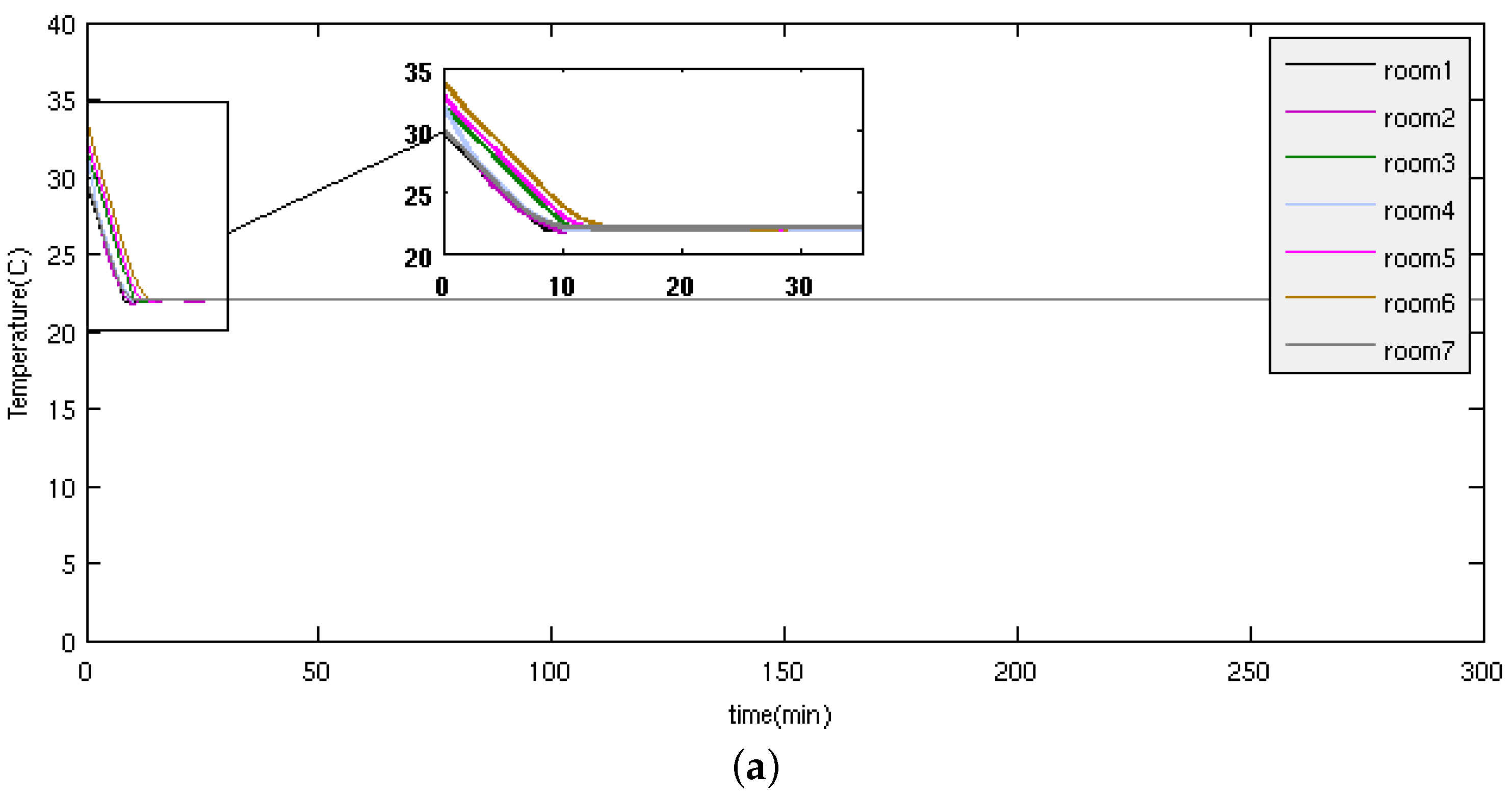
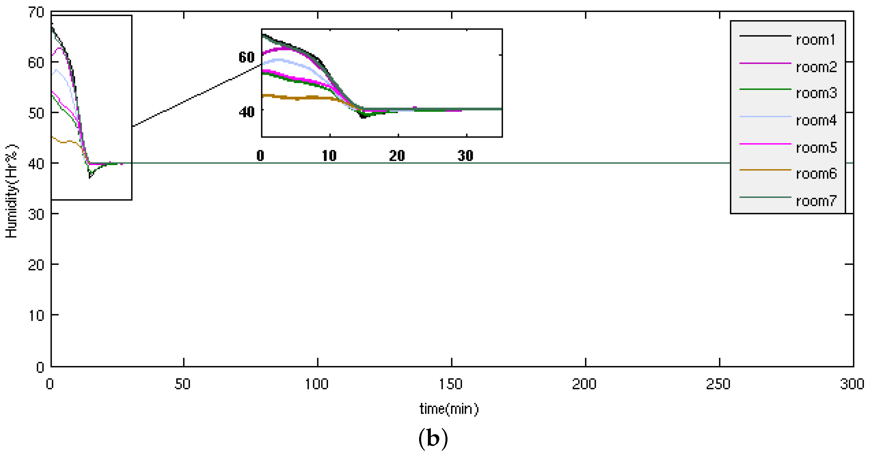
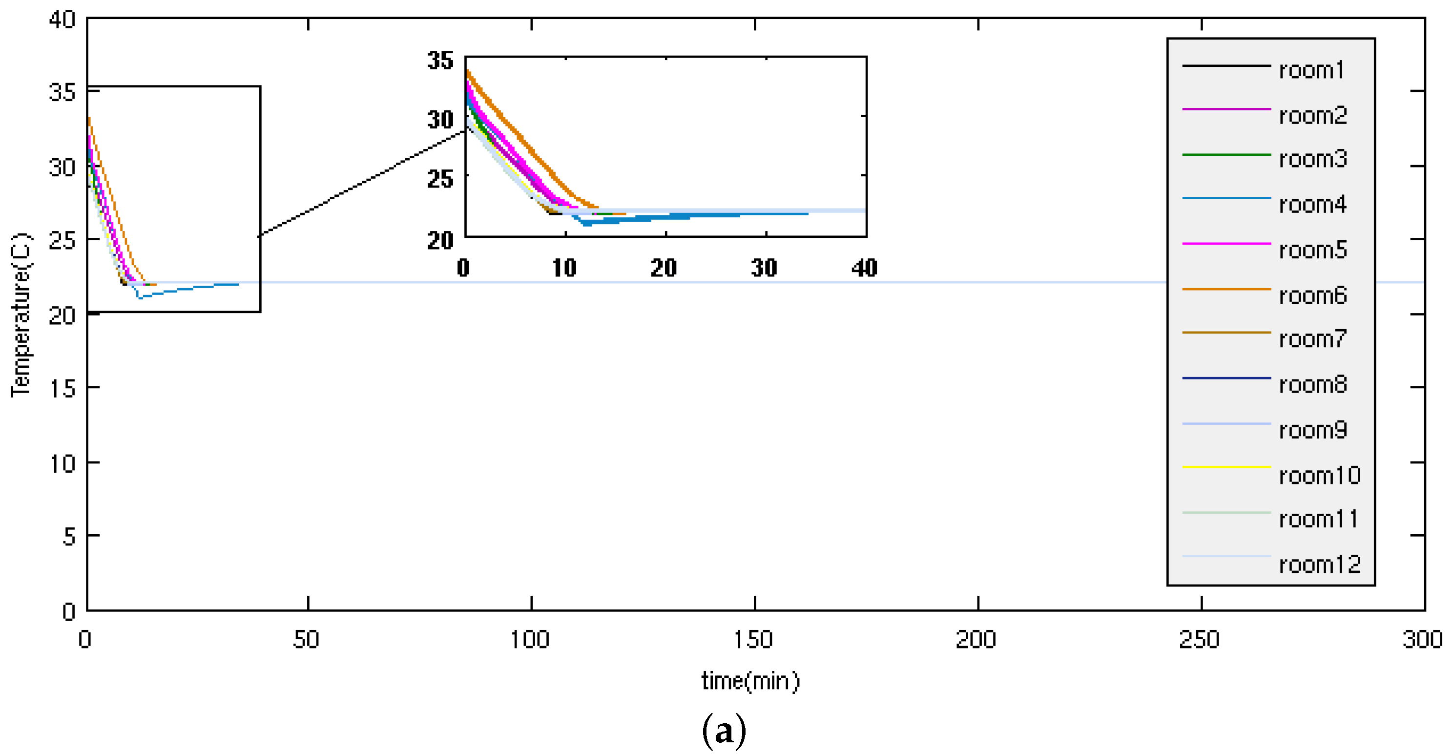
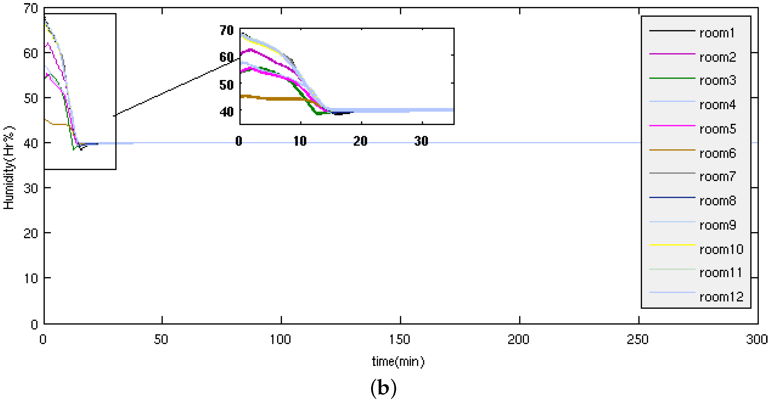
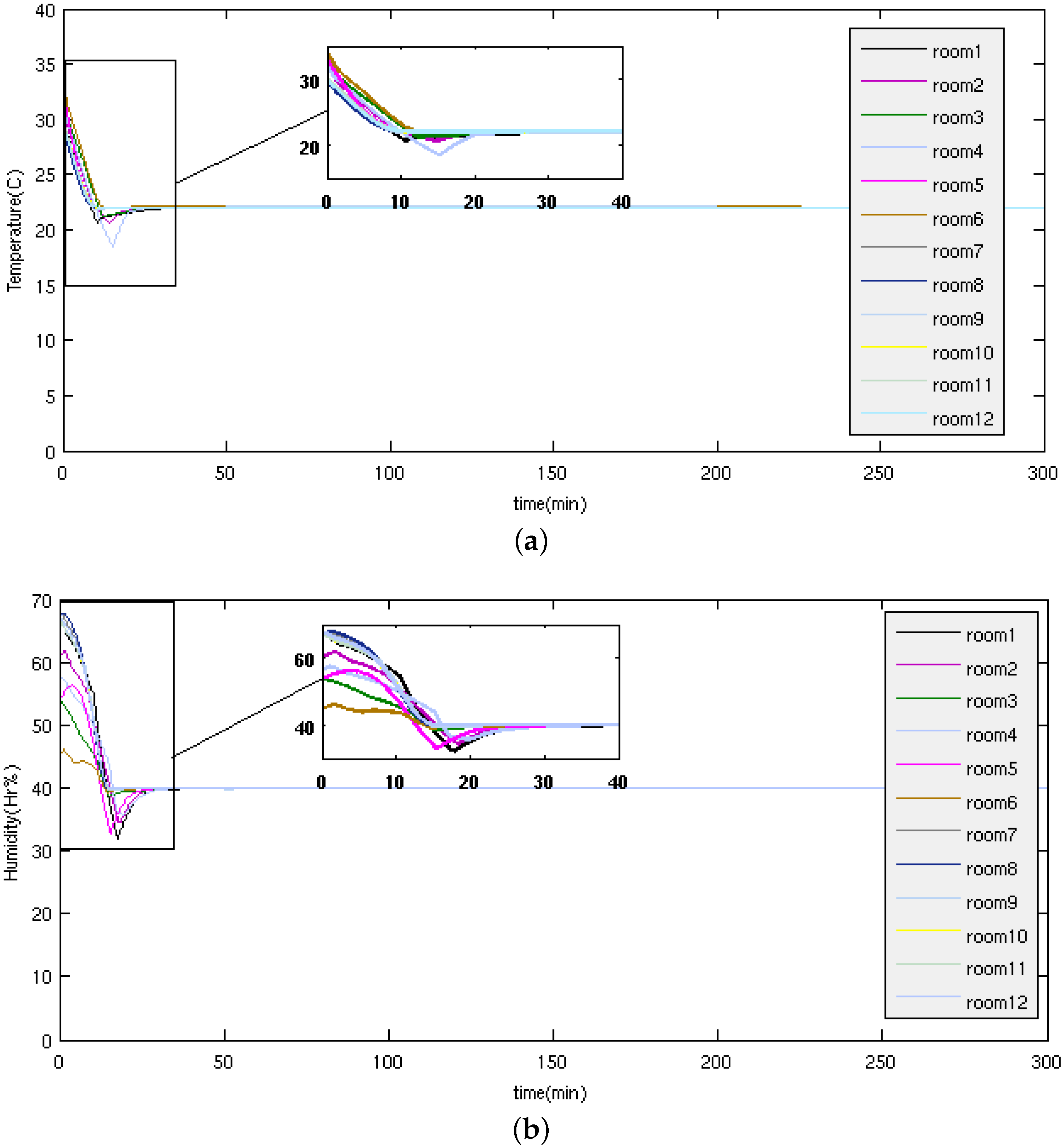
In
Figure 6a,b, the performance of the architecture system proposed in this paper is shown under the conditions mentioned before. It can be seen that the WSAN system presents a high performance, achieving robust fuzzy practical control, and it is possible to conclude that a simple and reliable fuzzy control without deploying derivative actions is sufficient and necessary to control a series of multi-evaporators in parallel, each controlling an operating room in a hospital with the ranges of temperature and humidity specified. However, the worst case regardless of disturbances (disturbances are additive and constant) is when they have the 12 rooms in operation, for which the design of the outdoor unit has previously been done.
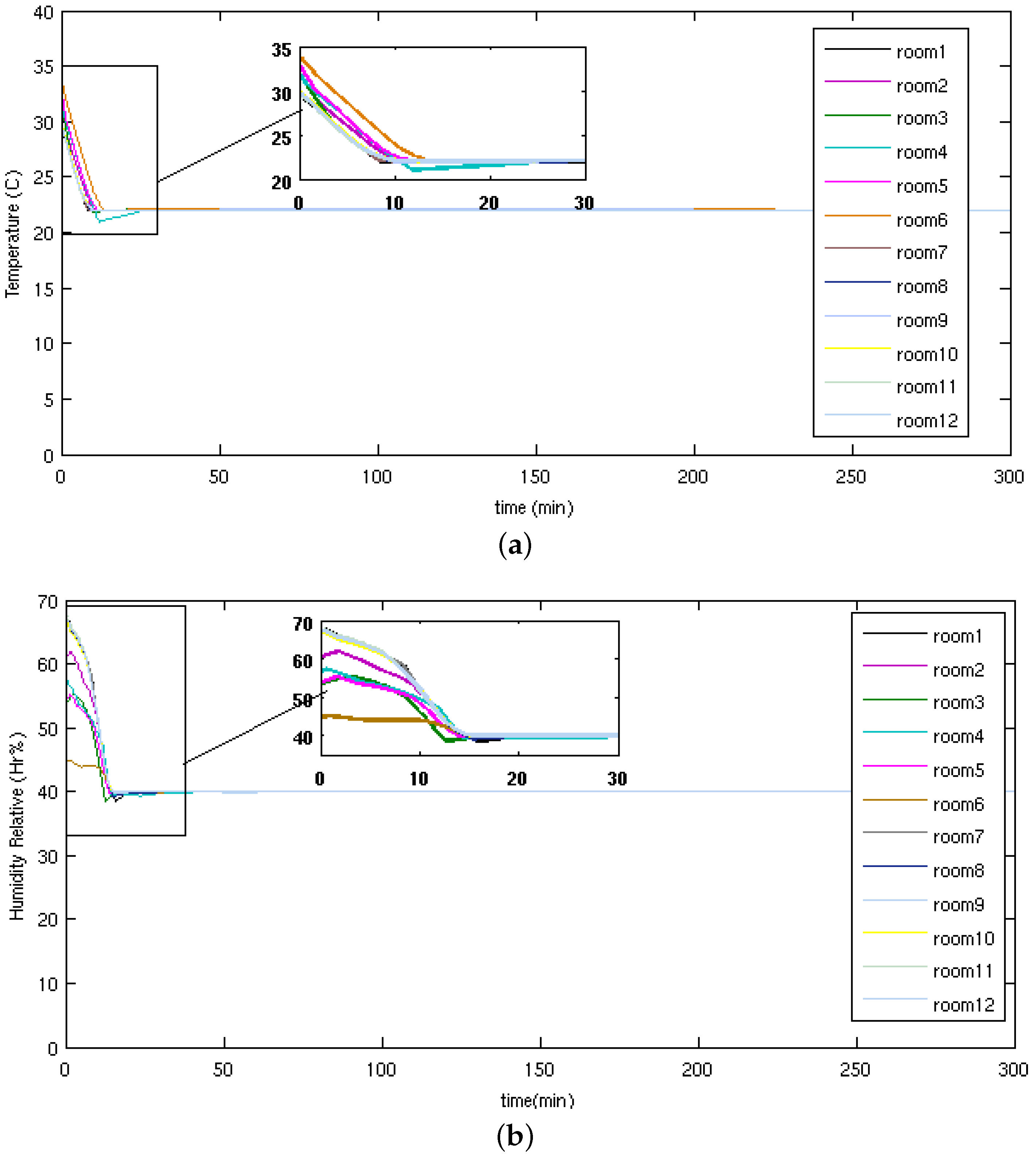
From the graphics given in the
Figure 8 and
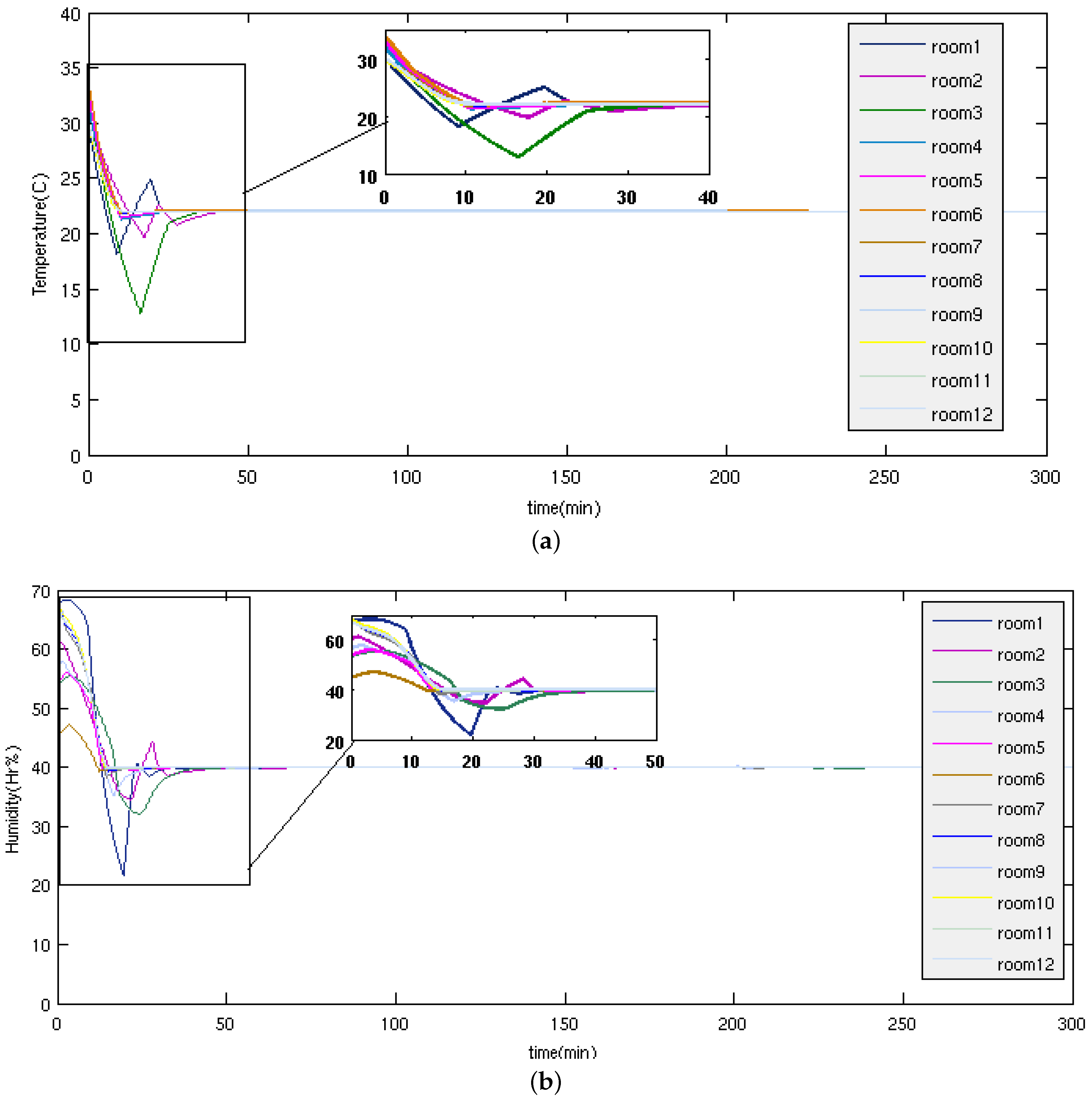
Figure 9a,b, it is possible to conclude that the fuzzy controller achieves the robust desired response. On the other hand, the high gain controllers could be quite sensitive to noise, and the real-time requirements have been addressed with a non-beacon or unslotted mode of 802.15.4 without affecting the response robustness. Finally, to examine the robust approach, mainly from compensation strategies when packet dropout occurs, packet loss percentages were imposed in the network for the case of 12 evaporators and 12 operating rooms (temperature and humidity control for 12 rooms), this case being the highest probability of failure, since it is when as many packets are transmitted over the network in the test example, which is presented graphically in
Figure 10a,b. The goal is to see the behavior under a packet loss rate, since each room may be altered by various disturbances during time.
In
Figure 10a,b is shown the performance of the architecture proposed in this paper under the conditions mentioned before. It can be seen that slaves (multi-evaporators and exhaust fan) and master (smart agent control) systems present a high performance, achieving robust practical synchronization. It is possible to conclude that the fuzzy logic controller achieves the synchronization, and the high gain controllers could be quite sensitive to noise. In the case of this example, with 50% of simulated packet loss, the behavior of the system is quite good and can be considered the limit degradation of responses.
In
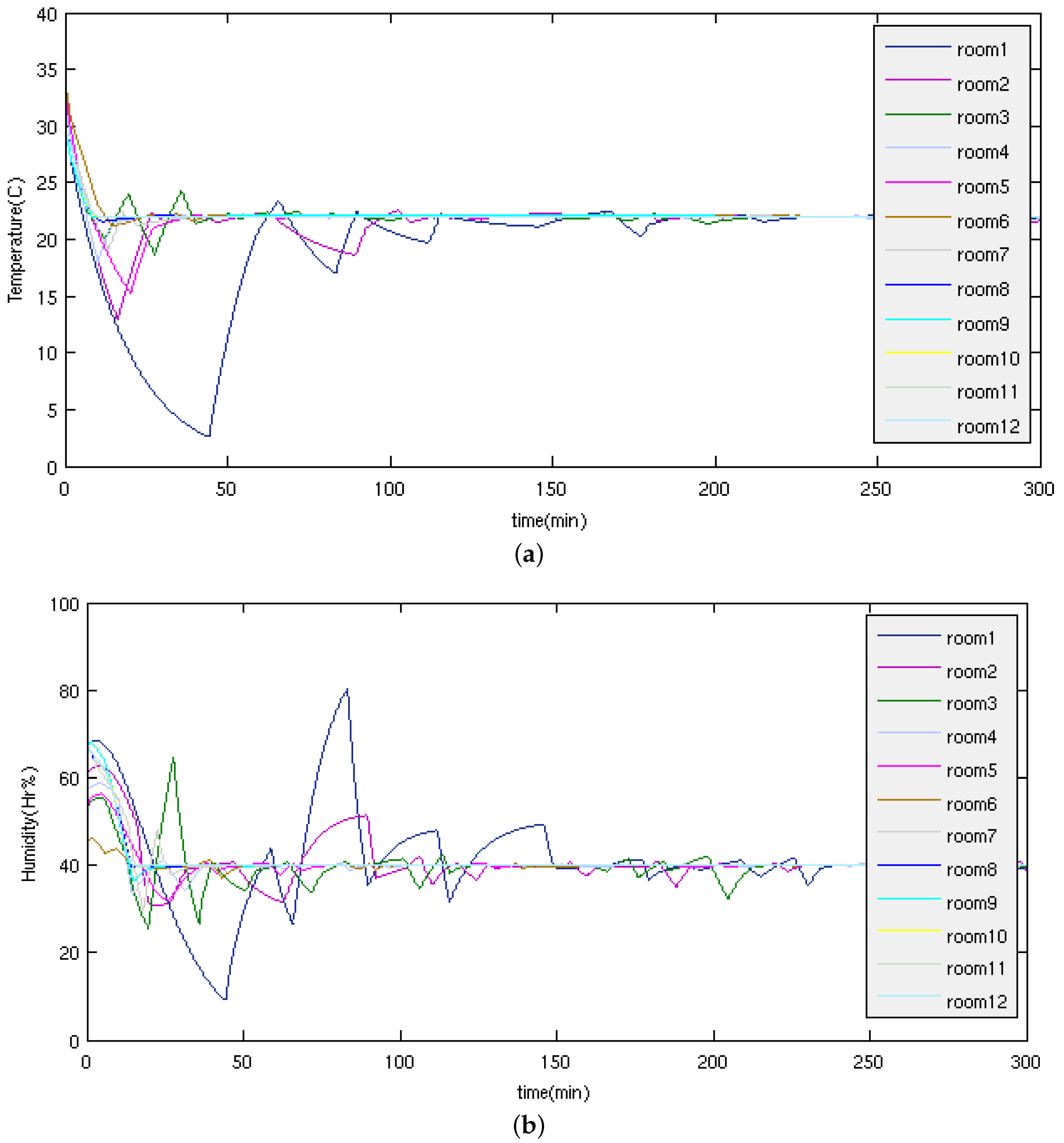
Figure 11a,b and
Figure 12a,b, a case of maximum tolerance to 60% lost packets is shown, keeping the same conditions and disturbances in the system (for 70% lost packets, the answer is not entirely desirable); however, it is important to mention that throughout this paper, the architecture implemented gives a strong priority to unsaturated networks and a network topology based on intermediate nodes, which prevents packet loss by collisions, distances and power, which are the main causes of packet loss in such networks; thus, the control performance to 60% packet loss is very acceptable in this architecture.
The main problem to be addressed in this work is the control of multiple or parallel plants, which should have an intelligent and flexible architecture based on multi-agent systems (MAS) that allows one to add or remove new plants or nodes online, without the need for reconfiguring the system, while maintaining temporal and functional restrictions in the system. Therefore, the flexibility in the architecture means that controllers must be independent of the dynamics of the network, i.e., they can be implemented, tested and configured independently and can be inserted into the network, supporting the features of the plants already in operation. Several reasons lead us to implement a controller based on fuzzy logic to control the set of multi-evaporators: all loops are controlled by the same smart controller that implements a fuzzy logic control for all multi-evaporators and exhaust fan systems, being executed in the CPU controller; fuzzy logic does not implement any derivative action for this application, so it is not required to keep the previous states, and the calculation of the control action is executed in an instant of time (ideal in multiple plants); the set points of temperature and humidity are given in a range and not as an absolute value, which is most simple and practical to establish for a fuzzy control; the fuzzy logic control does not require a strict mathematical model of the rooms, air conditioners and exhaust fans and cannot be the same, however, the outputs are properly maintained within the established ranges; finally, the master logic control system presents a high performance, achieving practically a robust synchronization, and high gain controllers, which could be quite sensitive to noise.
The scalability limits of closed control loops is mainly due to three aspects: the dynamics of the plants to be controlled, which establishes a minimum control period depending on its time constant; the structure of the network, which is linked to the physical spaces that should be controlled, as well as the quantity and order of data hops; and finally, linked to the anterior aspect, the independence of closed control loops and the quantity of hops necessary to bring the information to desired nodes (e.g., from smart sensors to the controller and from controller to smart actuators). For the temporal analysis, Equations (
8), (
9) and (
11) address this generality; however, for the specific approach to the control of multi-evaporators and the network structure presented in this paper, the dynamics of the plant sets a minimum period condition of at least 108 s (
s), it being desirable to be less than that value. Now considering the control loops with the worst cases of execution and transmission, the summation of each one of these imposes that the transmission time limit in the network cannot exceed 108 s, which is beyond the minimum control period of the farthest node, in its worst case of execution and transmission (only valid for this structure and network topology). Executing the three equations above and maintaining the same structure of the network, on the fifteenth loop (
i.e., 15 rooms to control), the worst case of execution and transmission of 102 s is obtained, which is the limit in the worst case execution; and therefore, the maximum supported for this network structure and computational and control strategy. There are other alternatives to improve the scalability limits, but all lead in most cases to structuring a communication network between sensors, actuators and controllers, so that the equations previously analyzed allow one to evaluate the behavior from the temporal point of view; and simulation includes additionally in this evaluation the functional aspects before a final deployment.
8. Conclusions
This work integrates several aspects, such as the fuzzy control of multiple evaporator air-conditioning systems with the IEEE 802.15.4 wireless network protocol, an end-to-end real-time analysis, as well as design methodologies. The problem of the control of multi-evaporator air-conditioning systems, in the presence of uncertainties, was tackled through a wireless fuzzy control approach. The advantages of this concept are that we can easily perform the optimization for a set of multi-evaporators controlled by the same controller, in spite of unknown dynamics and perturbations. The real-time requirements have been addressed with a non-beacon or unslotted mode of the IEEE 802.15.4 protocol, to obtain a greater scalability, the self-configuration of the network and the least overhead, ensuring minimal real-time features. Wireless communications and distributed architectures could be extremely helpful in the development of networked control systems in large spatially-distributed plants involving numerous sensors and actuators. The development and implementation of the parallel control of multi-evaporator systems has a particular relevance for its intensification, since it helps to avoid the high cost associated with huge multi-evaporator systems. However, the non-deterministic nature and concurrent behavior of such distributed systems makes their analysis and design a complex task. Thus, this work proposes a model architecture, where the main objective to meet the timing requirements for control multi-evaporator system is avoiding network congestion, implementing a system of aperiodic tasks, a simple, but efficient event-triggered sampling scheme and a smart compensatory control and smart actuator system; likewise, this work performed an analysis and a validation method for multiple control networks designed for parallel plants, consisting of multiple control loops closed over a wireless communication network. Finally, through the simulations and tests performed, we can conclude that the architecture and strategies implemented throughout this work are robust.


 ,
, 


