
Reduced-Capacity Inrush Current Suppressor Using a Matrix Converter in a Wind Power Generation System with Squirrel-Cage Induction Machines

Abstract
:1. Introduction
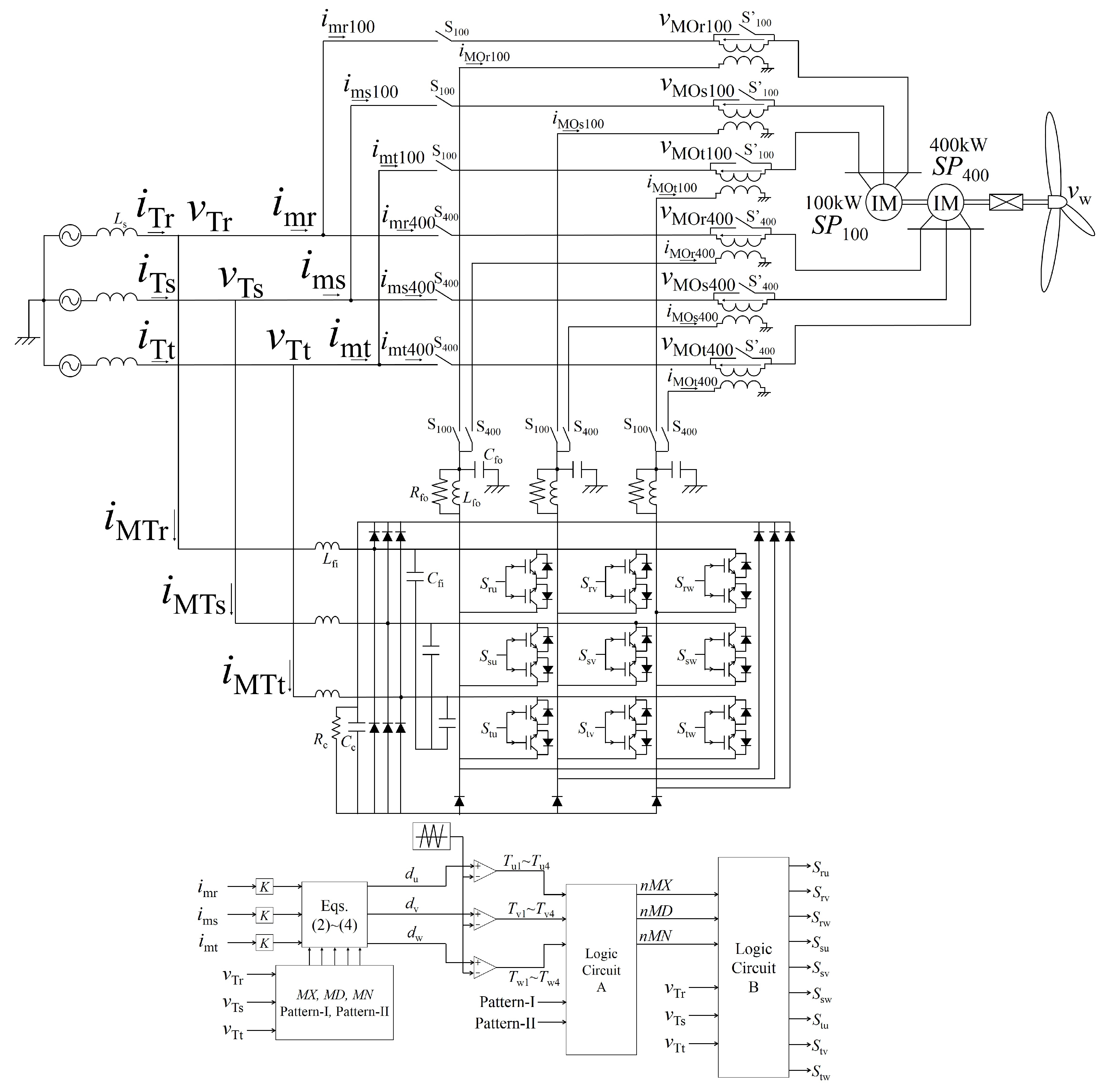
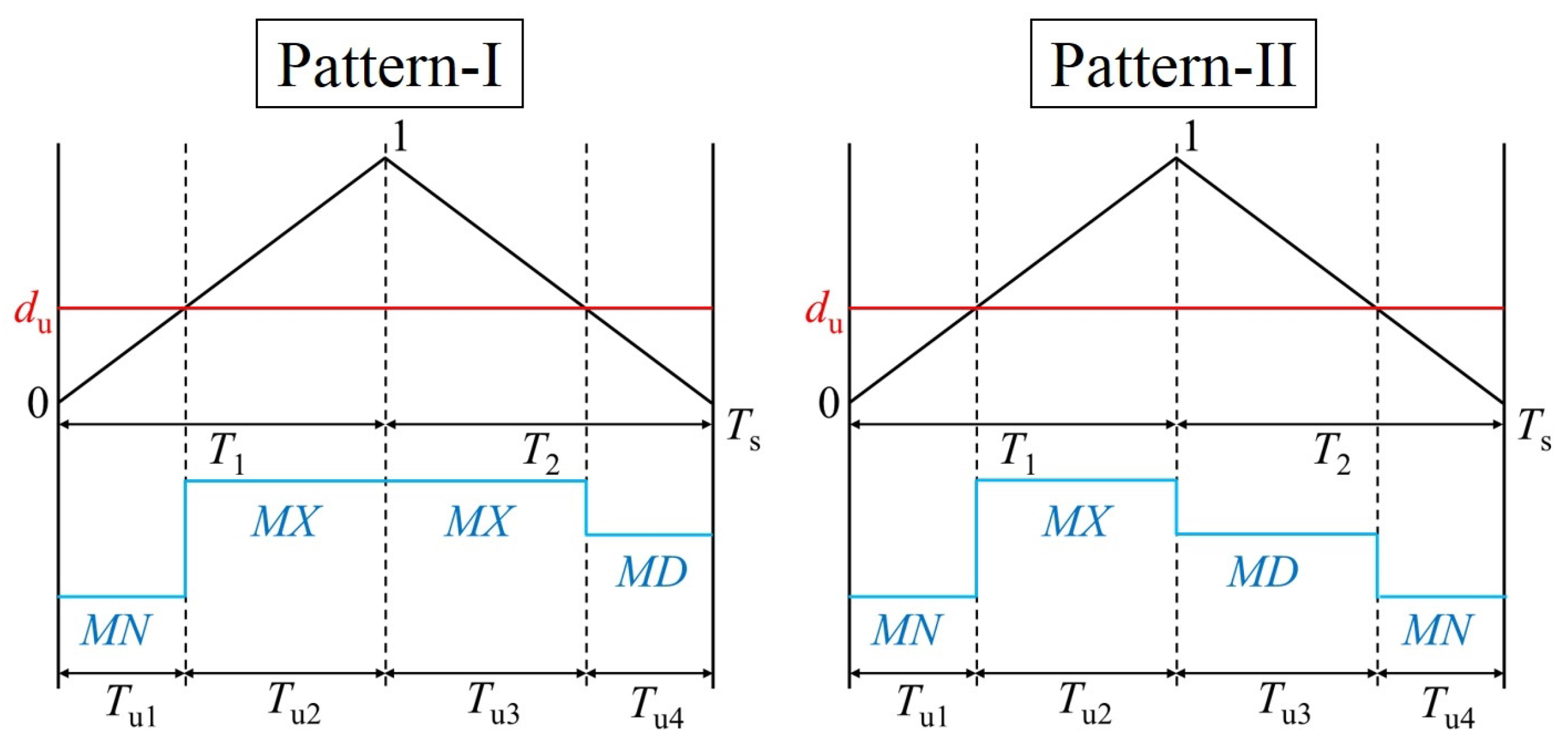
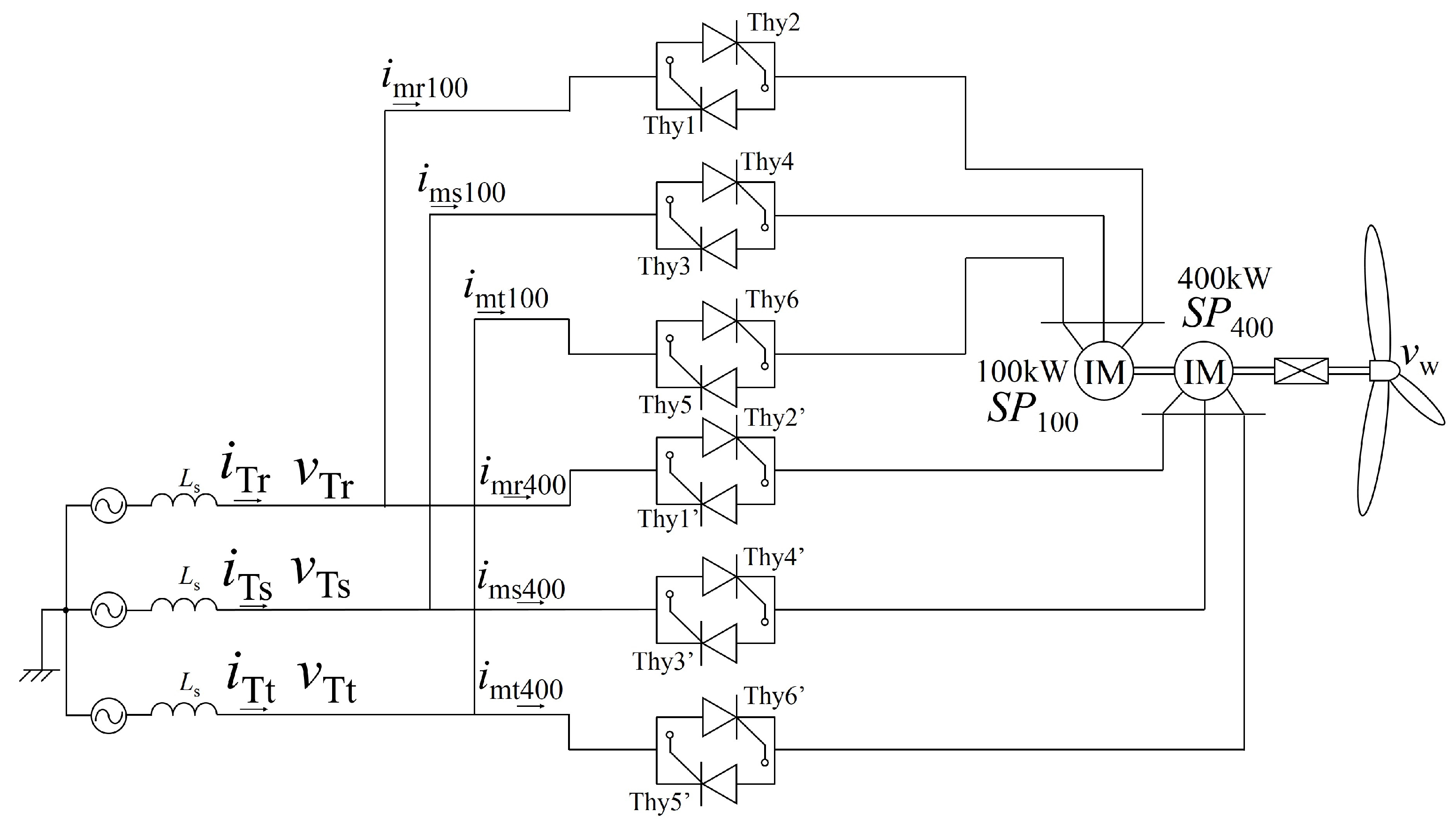
2. Inrush Current Suppressor Using MC
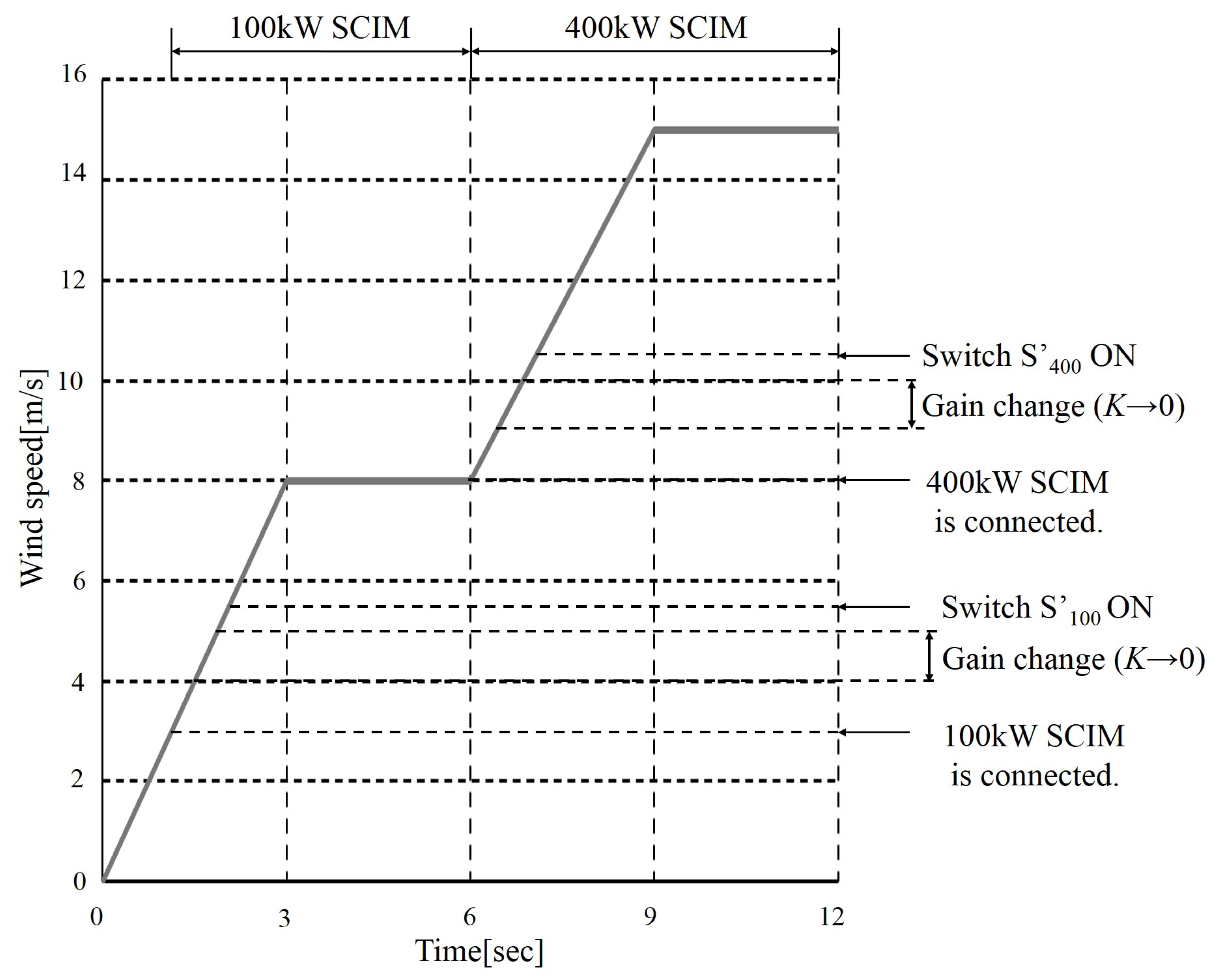
3. Simulation Results
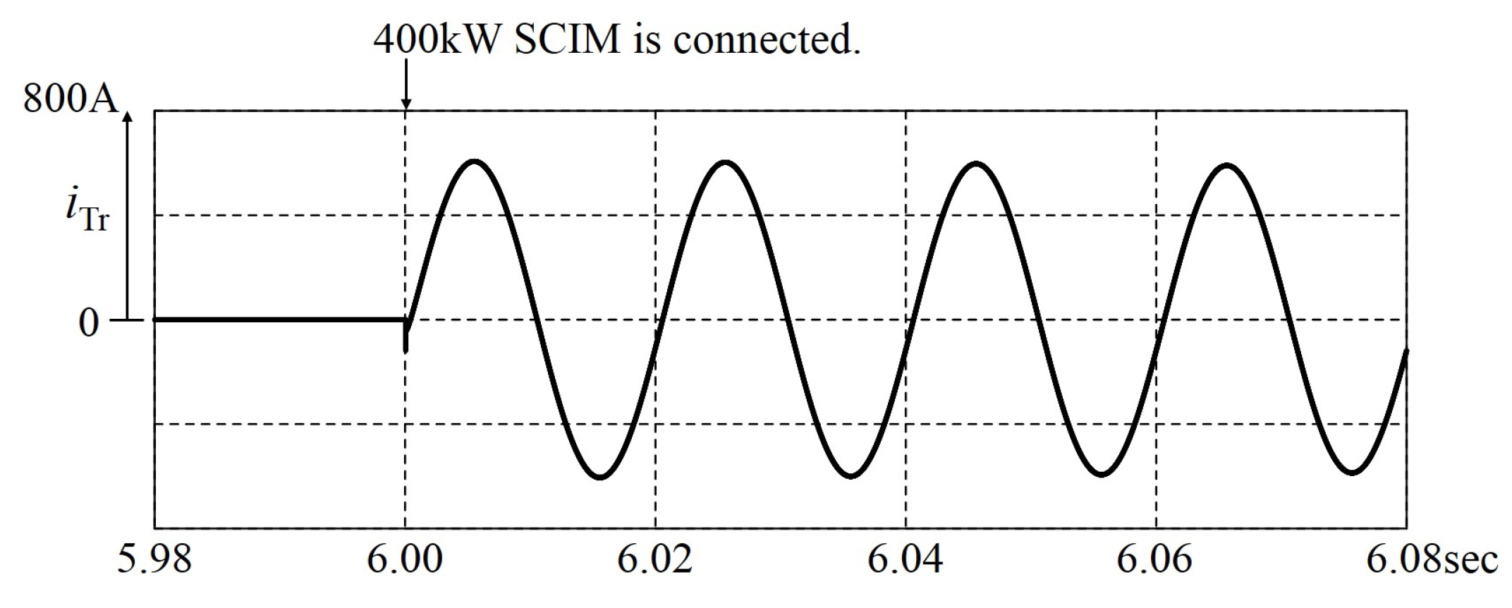
3.1. Simulation Results of Direct Connection
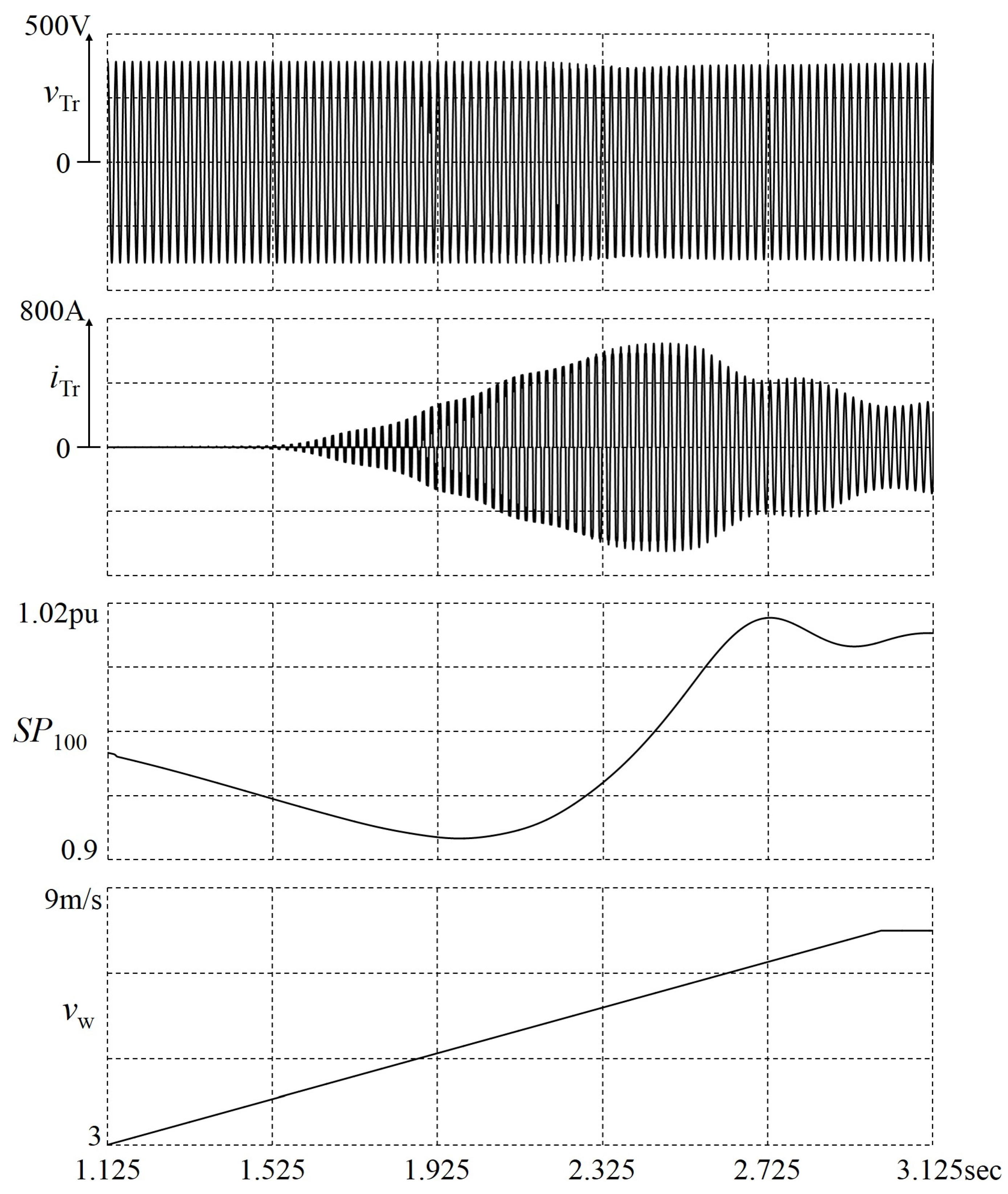
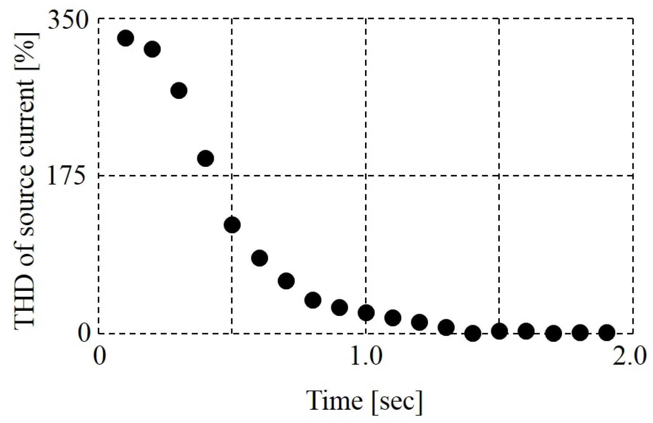
3.2. Conventional Inrush Current Suppressors
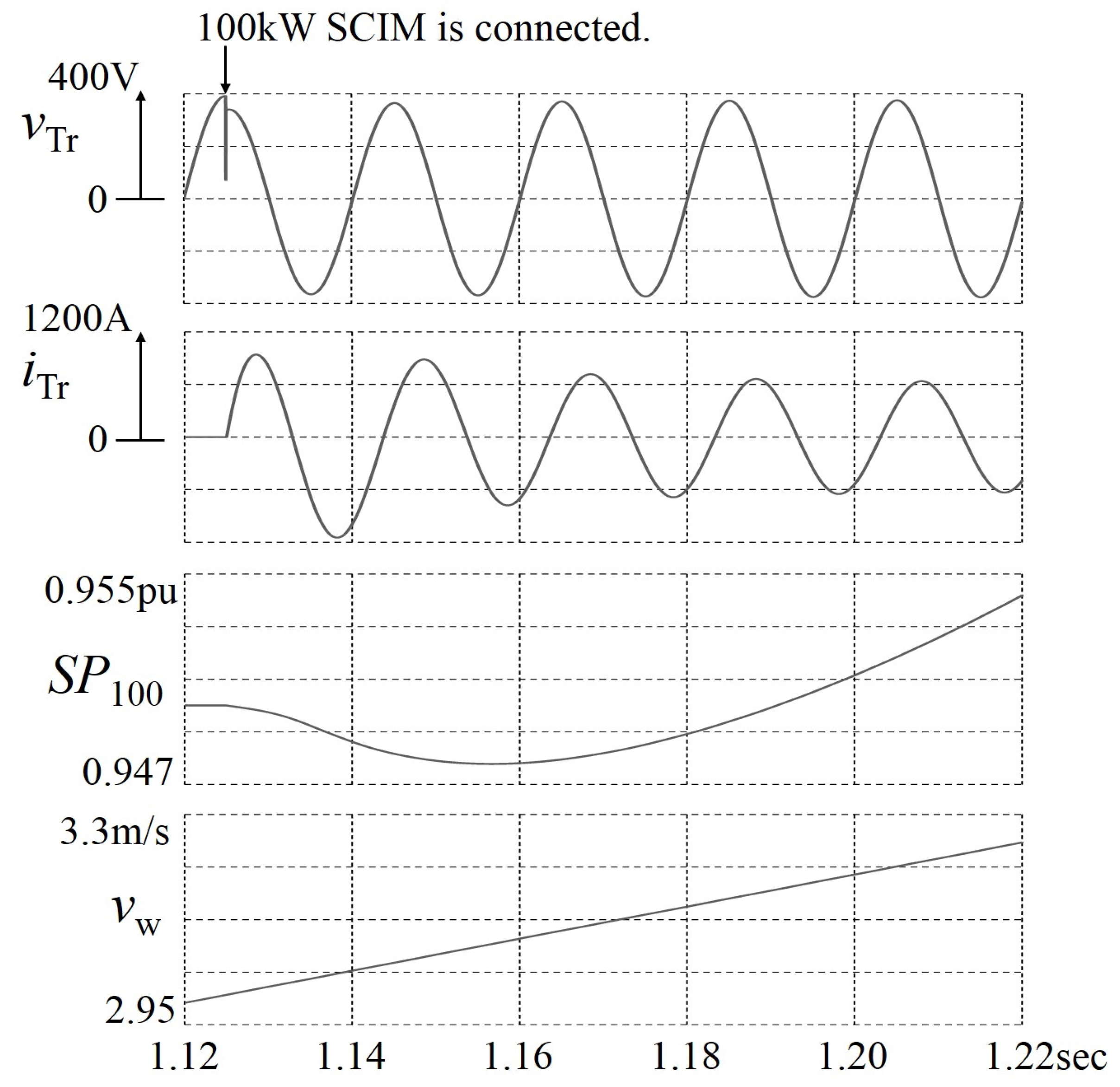
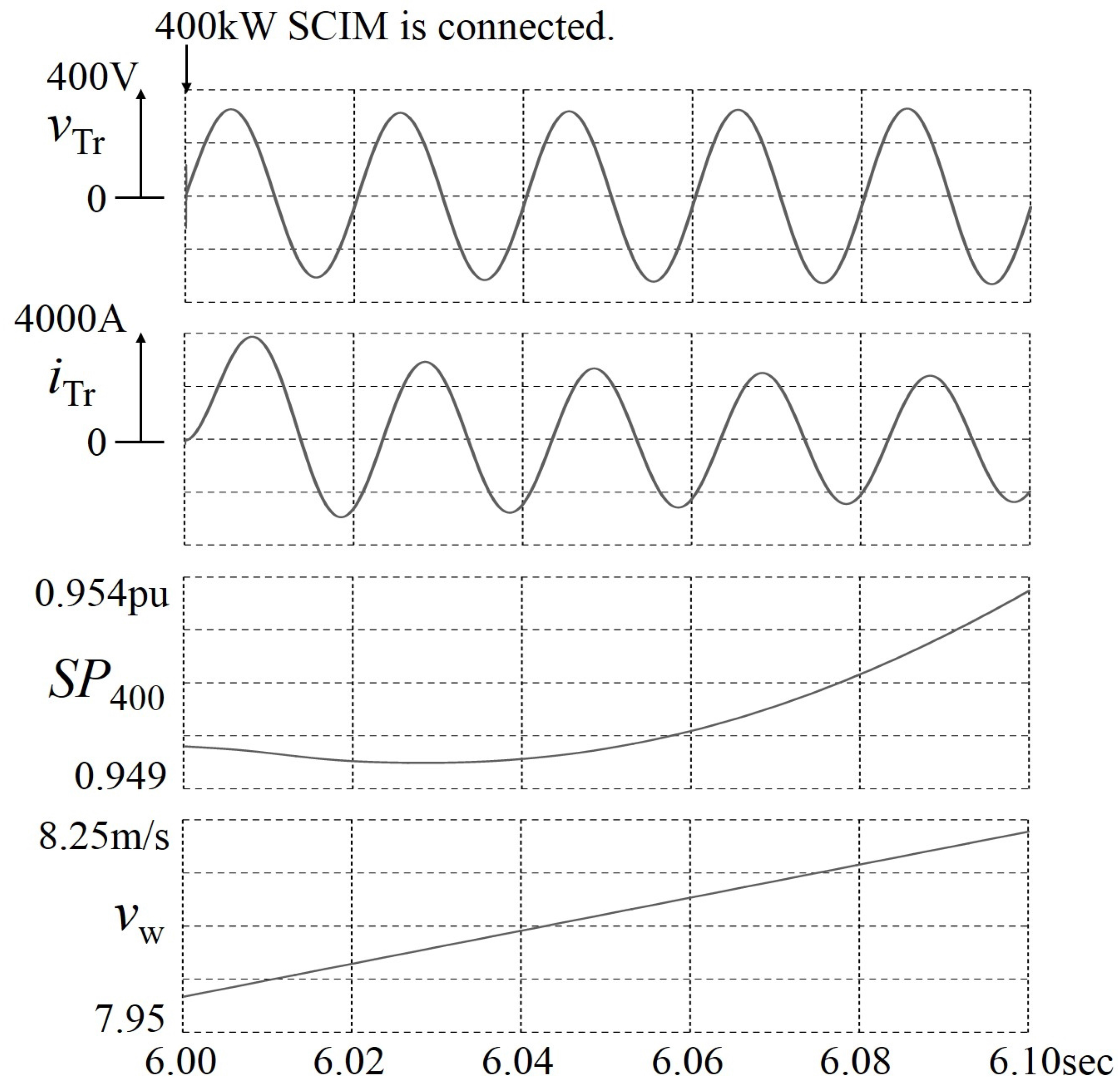
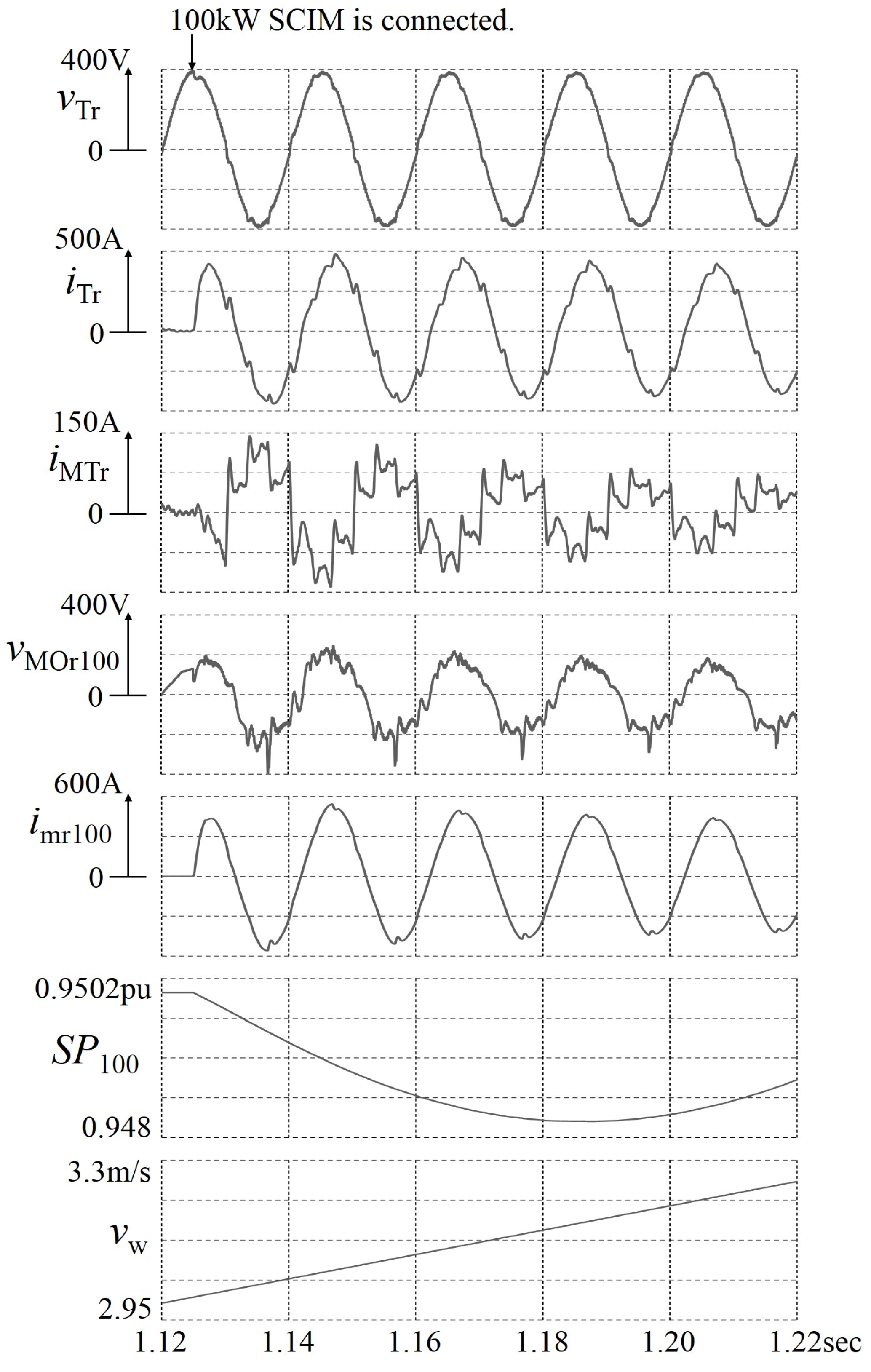
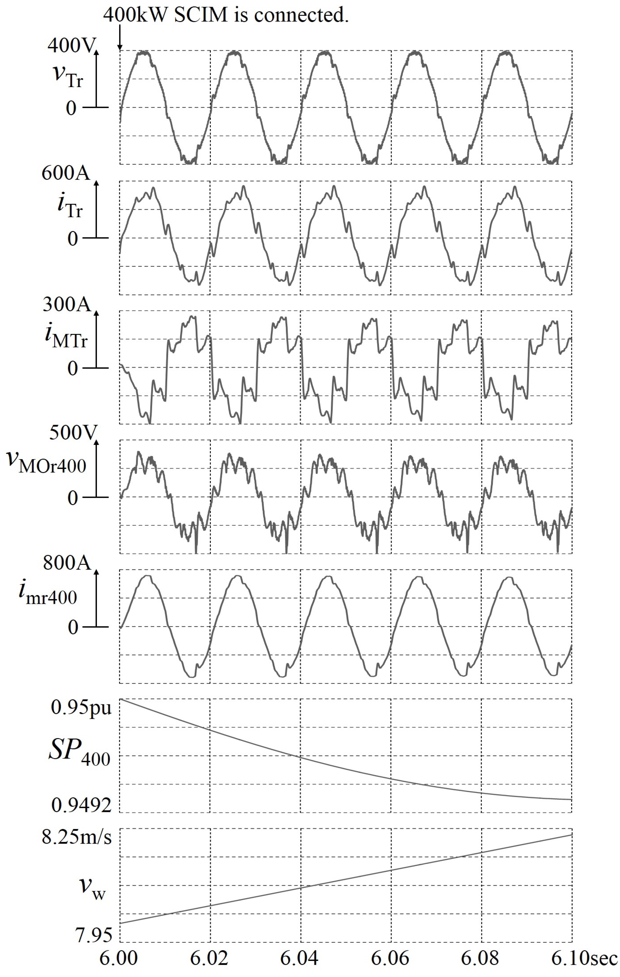
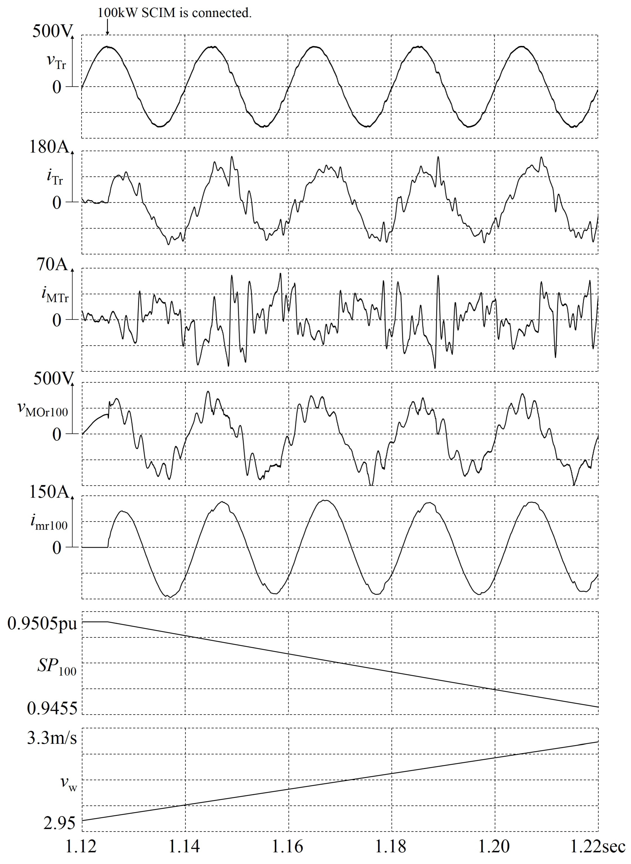
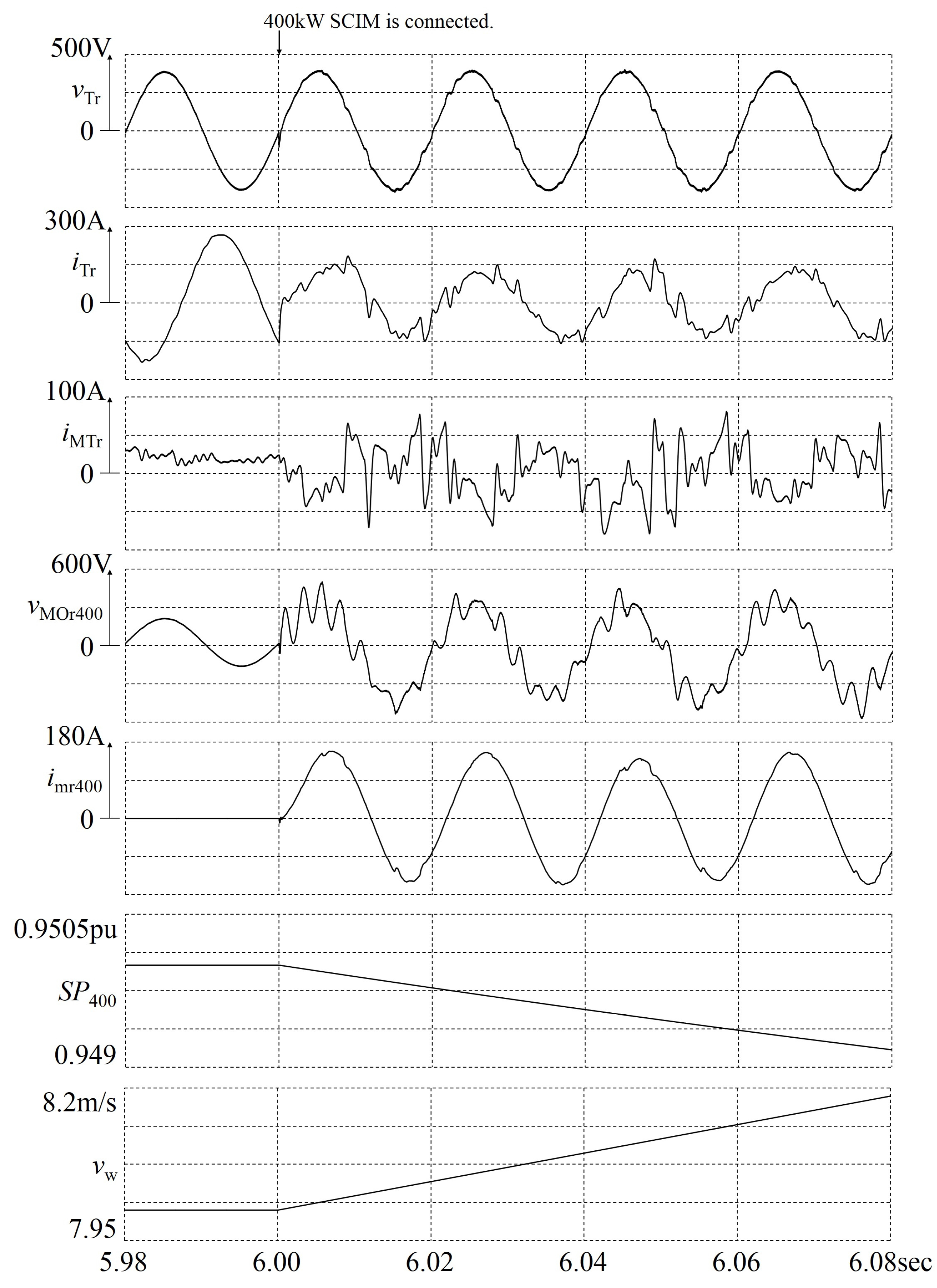
3.3. Simulation Results with the Proposed Inrush Current Suppressor
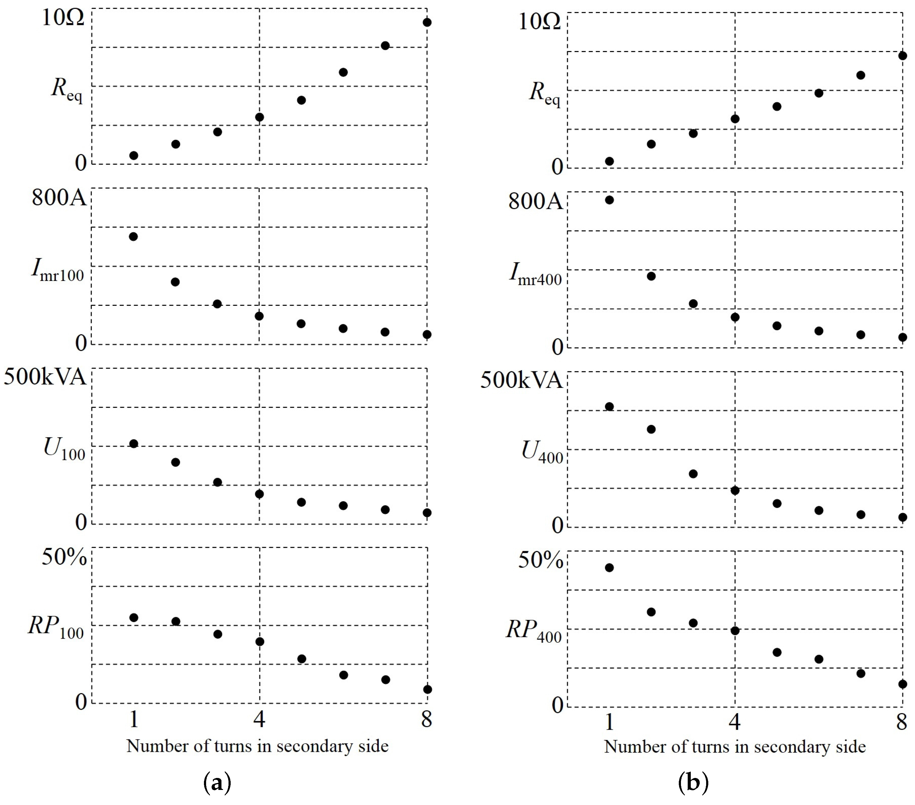
3.4. Reduction of the Capacity for the Proposed Inrush Current Suppressor
4. Conclusions
Author Contributions
Conflicts of Interest
References
- Global Wind Energy Council. Grobal Wind Energy Outlook 2014. Available online: http://www.gwec.net/wp-content/upload/2015/03/GWEC_Global_Wind_2014_Report_LR.pdf (accessed on 11 November 2015).
- Thiringer, T.; Petru, T.; Lundberg, S. Flicker contribution from wind turbine installations. IEEE Trans. Energy Convers. 2004, 19, 157–163. [Google Scholar] [CrossRef]
- Medina-Domínguez, E.J.; Medina-Padrón, J.F. Critical clearing time and wind power in small isolated power systems considering inertia emulation. Energies 2015, 8, 12669–12684. [Google Scholar] [CrossRef]
- Shinohara, K.; Yamamoto, K.; Iimori, K.; Minari, Y.; Sakata, O.; Miyata, M. Compensating for magnetizing inrush currents in transformers using PWM inverter. IEEJ. Trans. Ind. Appl. 2004, 124, 1173–1181. [Google Scholar] [CrossRef]
- Yamada, H.; Enami, M.; Hiraki, E.; Tanaka, T. A new method of compensating harmonic currents for wind power generation systems with the soft starter using a hybrid active filter. In Proceedings of the Power Conversion Conference 2007, Nagoya, Japan, 2–5 April 2007; pp. 404–409.
- Thiringer, T. Grid-friendly connecting of constant-speed wind turbines using external resistors. IEEE Trans. Energy Convers. 2002, 17, 537–542. [Google Scholar] [CrossRef]
- Yamada, H.; Hanamoto, T. A novel method of suppressing inrush currents of squirrel-cage induction machine using matrix converter in wind power generation systems. In Proceedings of the 2012 International Conference on Renewable Energy Research and Applications (ICRERA), Nagasaki, Japan, 11–14 November 2012; pp. 1–4.
- Hara, H.; Yamamoto, E.; Yamada, T.; Oyama, J.; Higuchi, T.; Abe, T. Analysis of control performance of matrix converter in a high-speed region using circuit simulator. In Proceedings of the Power Conversion Conference 2007, Nagoya, Japan, 2–5 April 2007; pp. 1072–1077.
- Ito, J.; Sato, I.; Ohguchi, H.; Sato, K.; Odaka, A.; Eguchi, N. A control method for the matrix converter based on virtual AC/DC/AC conversion using carrier comparison method. IEE Jpn. Ind. Appl. 2004, 124, 457–463. [Google Scholar] [CrossRef]
- Tadano, Y.; Hamada, S.; Urushibata, S.; Nomura, M.; Sato, Y.; Ishida, M. A space vector modulation scheme for matrix converter that gives top priority to the improvement of the output control performance. IEE Jpn. Ind. Appl. 2008, 128, 631–641. [Google Scholar] [CrossRef]
- Yoon, Y.D.; Sul, S.K. Carrier-based modulation method for matrix converter with input power factor control and under unbalanced input voltage conditions. In Proceedings of the Twenty Second Annual IEEE Applied Power Electronics Conference, Anaheim, CA, USA, 25 February–1 March 2007; pp. 310–314.
- Rodriguez, J.; Rivera, M.; Kolar, J.W.; Wheeler, P.W. A review of control and modulation methods for matrix converters. IEEE Trans. Ind. Electron. 2012, 59, 58–70. [Google Scholar] [CrossRef]
- Li, Y.; Choi, N.S.; Han, B.M.; Kim, K.M.; Lee, B.; Prak, J.H. Direct duty ratio pulse width modulation method for matrix converters. Int. J. Control Autom. Syst. 2008, 6, 660–669. [Google Scholar]
- Yamada, H.; Hanamoto, T. A novel method of suppressing inrush currents of squirrel-cage induction machine using matrix converter in wind power generation systems. In Proceedings of the International Power Electronics Conference (IPEC 2014), Hiroshima, Japan, 18–21 May 2014; pp. 538–542.
- Alesina, A.; Venturini, M.G.B. Analysis and design of oprimum-amplitude nine-switch direct AC-AC converters. IEEE Trans. Power Electron. 1989, 4, 101–112. [Google Scholar] [CrossRef]


| Item | 100-kW SCIM | 400-kW SCIM |
|---|---|---|
| Rated power (kW) | 100 | 400 |
| Rated phase voltage (V) | 277.13 | 277.13 |
| Rated phase current (A) | 120.28 | 481.12 |
| Rated frequency (Hz) | 50 | 50 |
| Number of pole | 6 | 4 |
| Synchronous speed (rpm) | 1000 | 1500 |
| Rated wind speed (m/s) | 8 | 15 |
| Item | Value |
|---|---|
| Source voltage Vs (V) | 480 |
| Source frequency f (Hz) | 50 |
| Source inductor Ls (mH) | 0.1 |
| Inductor of input filter Lfi (mH) | 1 |
| Capacitor of input filter Cfi (μF) | 25 |
| Inductor of output filter Lfo (mH) | 0.25 |
| Capacitor of output filter Cfo (μF) | 100 |
| Resistor of output filter Rfo (Ω) | 1 |
| Resistor of clamp circuit Rc (Ω) | 1000 |
| Capacitor of clamp circuit Cc (μF) | 500 |
| Item | Inrush Current (A) | Voltage Sag (%) | THD of Source Current (%) | Losses (kW) | |
|---|---|---|---|---|---|
| Direct connection | 100-kW SCIM | 1145 | 6.9 | 0.08 | - |
| 400-kW SCIM | 3873 | 15.3 | 1.1 | - | |
| Proposed inrush current suppressor (turn ratio is 1:1) | 100-kW SCIM | 558 | 1.5 | 7.71 | 14.2 |
| 400-kW SCIM | 718 | 0.76 | 15.6 | 38.7 | |
| Proposed inrush current suppressor (turn ratio is 1:4) | 100-kW SCIM | 146 | 1.0 | 20.9 | 6.5 |
| 400-kW SCIM | 158 | 0.5 | 23.9 | 9.2 | |
| Soft-starter | 100-kW SCIM | 649 | 6.6 | 328.8 | - |
| 400-kW SCIM | 1941 | 13.8 | 329.9 6 | - | |
| External resistors | 100–kW SCIM | 512 | 1.0 | - | 119.0 |
| 400 kW-SCIM | 609 | 0.8 | - | 212.6 | |
© 2016 by the authors; licensee MDPI, Basel, Switzerland. This article is an open access article distributed under the terms and conditions of the Creative Commons by Attribution (CC-BY) license (http://creativecommons.org/licenses/by/4.0/).
Share and Cite
Shibata, S.; Yamada, H.; Tanaka, T.; Okamoto, M. Reduced-Capacity Inrush Current Suppressor Using a Matrix Converter in a Wind Power Generation System with Squirrel-Cage Induction Machines. Energies 2016, 9, 223. https://0-doi-org.brum.beds.ac.uk/10.3390/en9030223
Shibata S, Yamada H, Tanaka T, Okamoto M. Reduced-Capacity Inrush Current Suppressor Using a Matrix Converter in a Wind Power Generation System with Squirrel-Cage Induction Machines. Energies. 2016; 9(3):223. https://0-doi-org.brum.beds.ac.uk/10.3390/en9030223
Chicago/Turabian StyleShibata, Sho, Hiroaki Yamada, Toshihiko Tanaka, and Masayuki Okamoto. 2016. "Reduced-Capacity Inrush Current Suppressor Using a Matrix Converter in a Wind Power Generation System with Squirrel-Cage Induction Machines" Energies 9, no. 3: 223. https://0-doi-org.brum.beds.ac.uk/10.3390/en9030223