
Modelling, Testing and Analysis of a Regenerative Hydraulic Shock Absorber System


Abstract
:1. Introduction
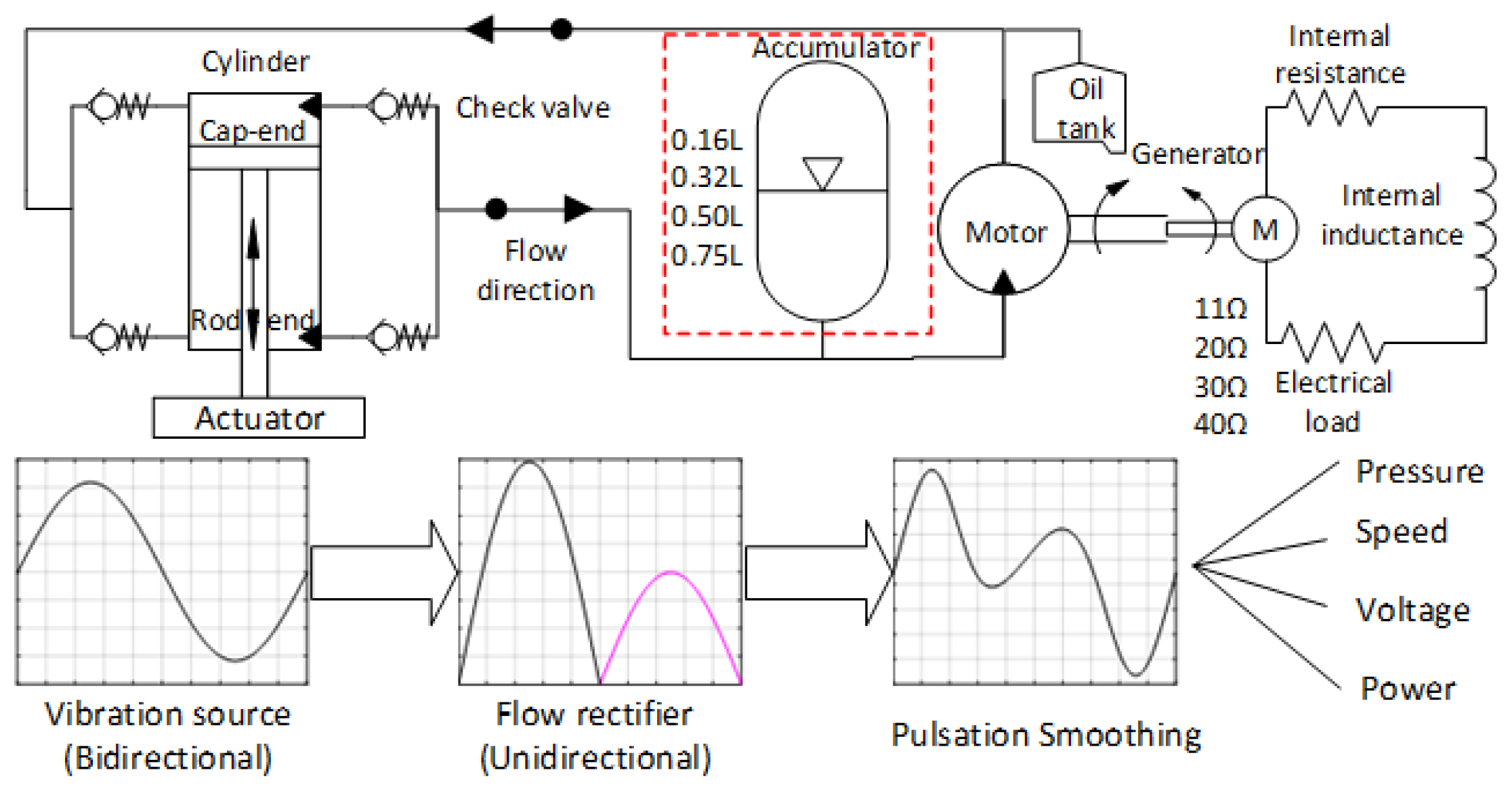
2. System Schematic
3. System Modelling and Prototype Development
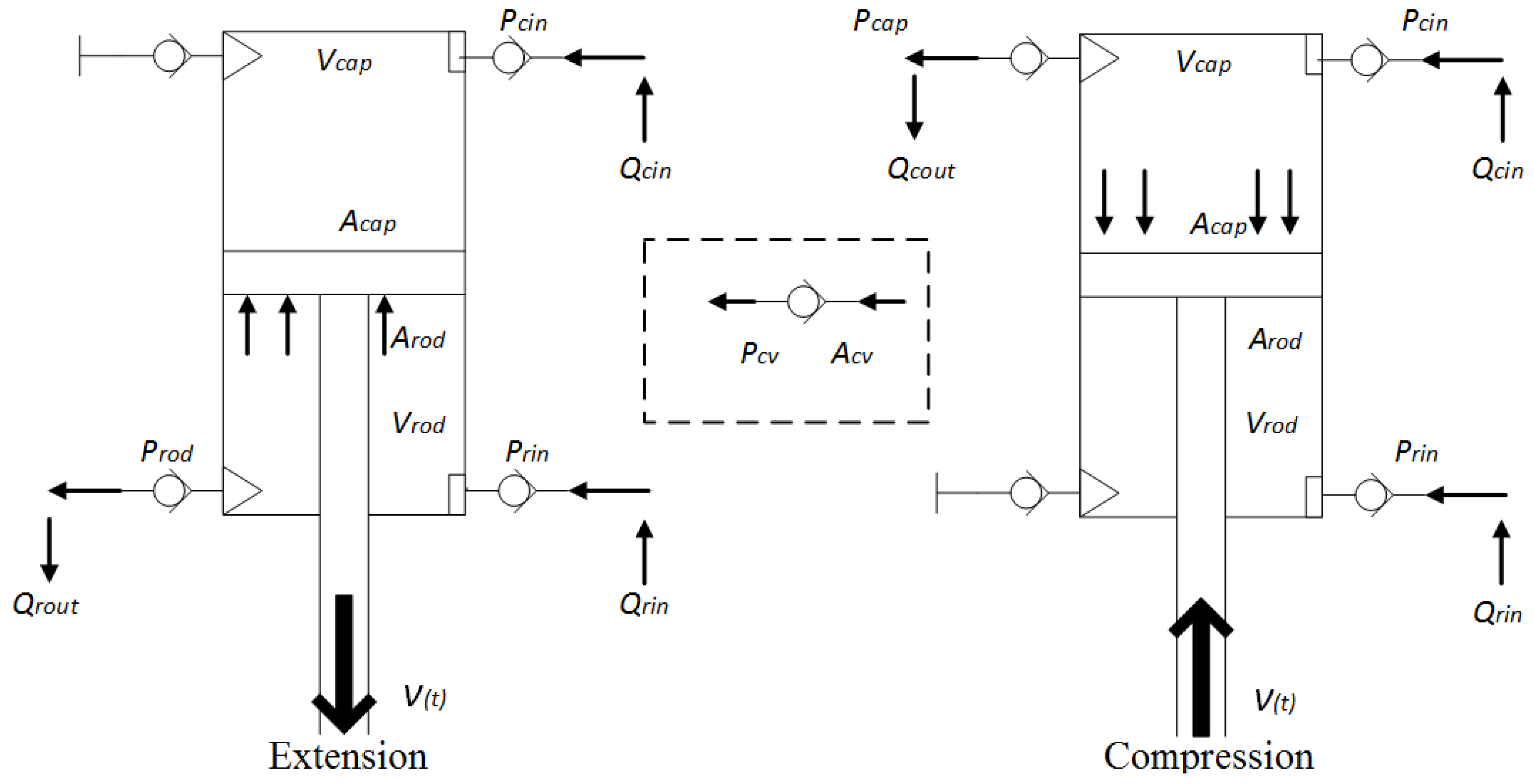
3.1. Hydraulic Flow
3.1.1. Vibration Excitation
3.1.2. Flow across Check Valves
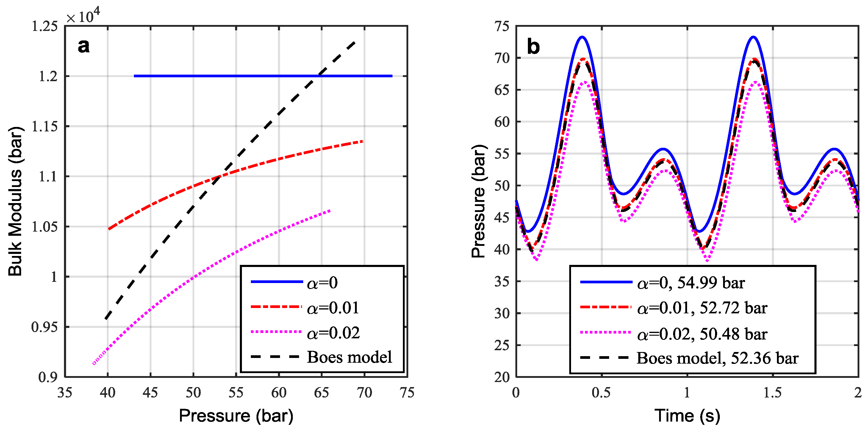
3.1.3. Gas-Charged Accumulator Flow
- (1)
- The gas-charged accumulator is assumed to be adiabatic, ignoring the heat exchange that happens between the gas and oil under conditions of rapid-cycling.
- (2)
- There are no frictions or thermal losses occurring during the charge/discharge cycles in the accumulator model. When the accumulator is running under variable pressure, thermal losses caused by variation in the gas temperature will inevitably influence gas behaviour.
- (3)
- The pressures in the fluid chamber instead of those in the gas chamber are used for flow rate calculation, which is reasonable because of the transient pressure balance inside the accumulator.
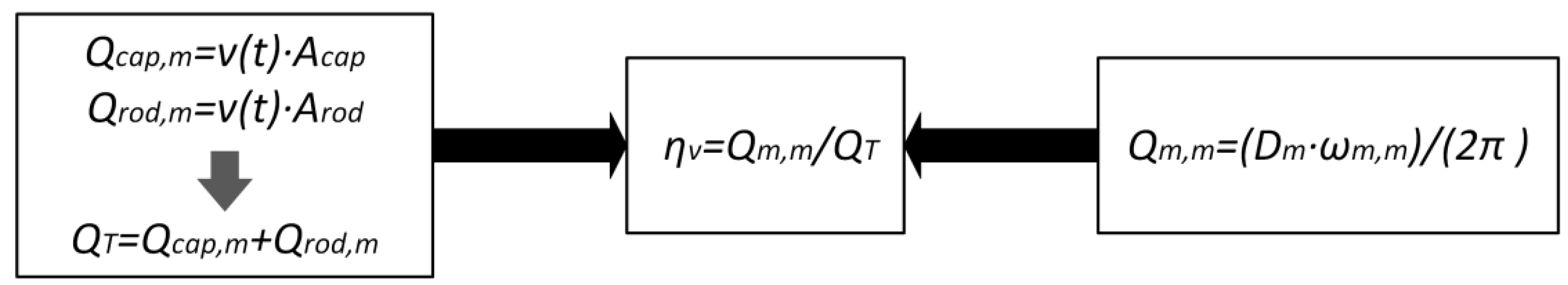
3.1.4. Flow through the Hydraulic Motor
3.2. Rotational Motion
3.3. Electrical Power
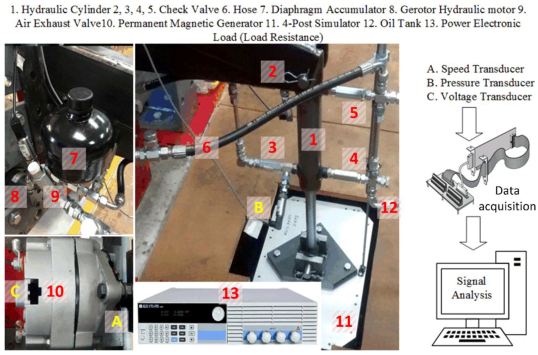
3.4. Fabrication of the Prototype
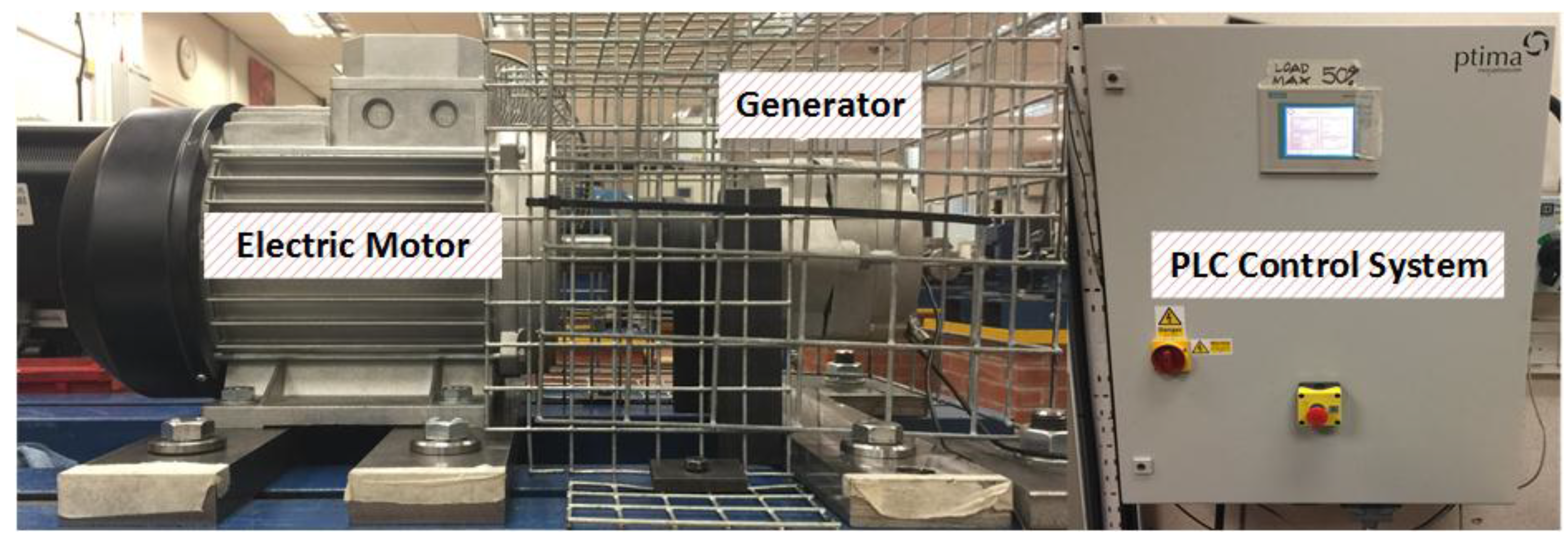
3.5. Test System and Measurement
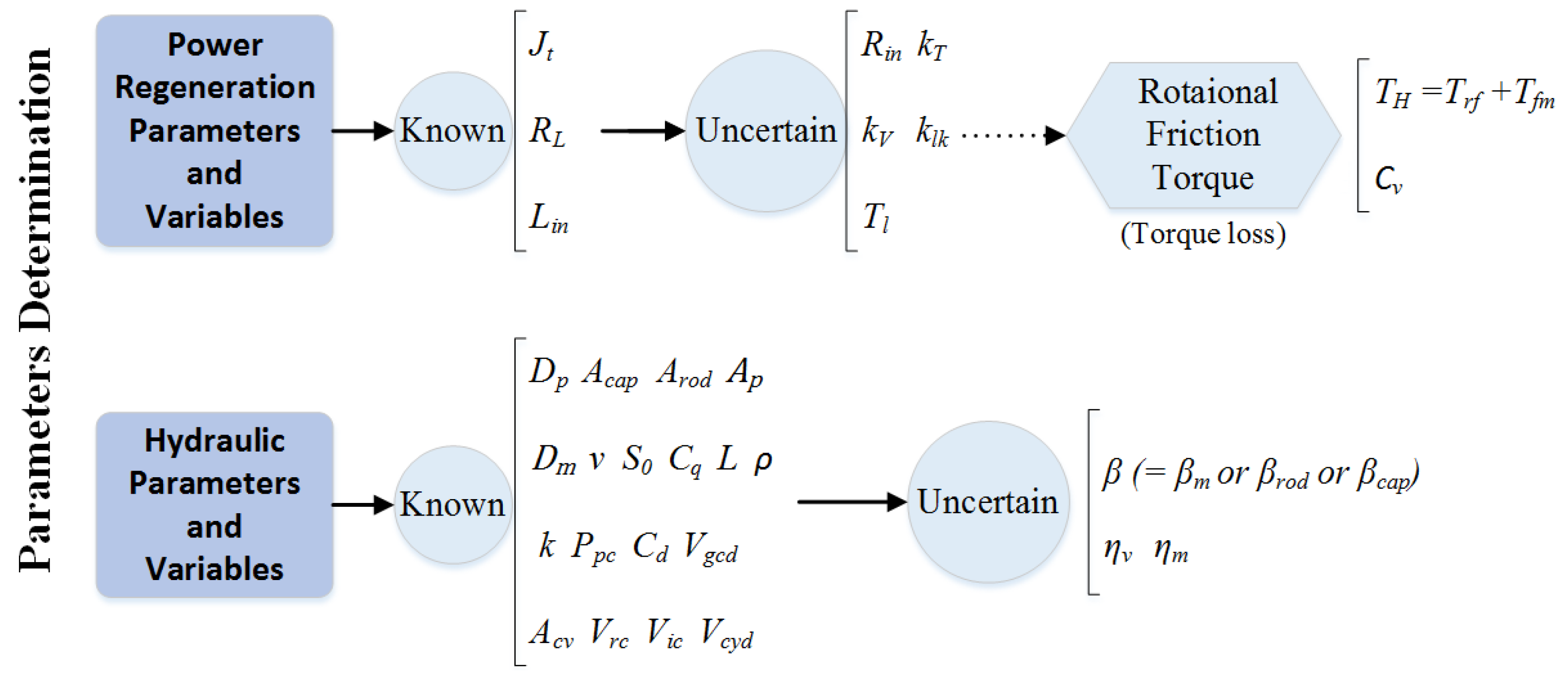
4. Parameter Studies
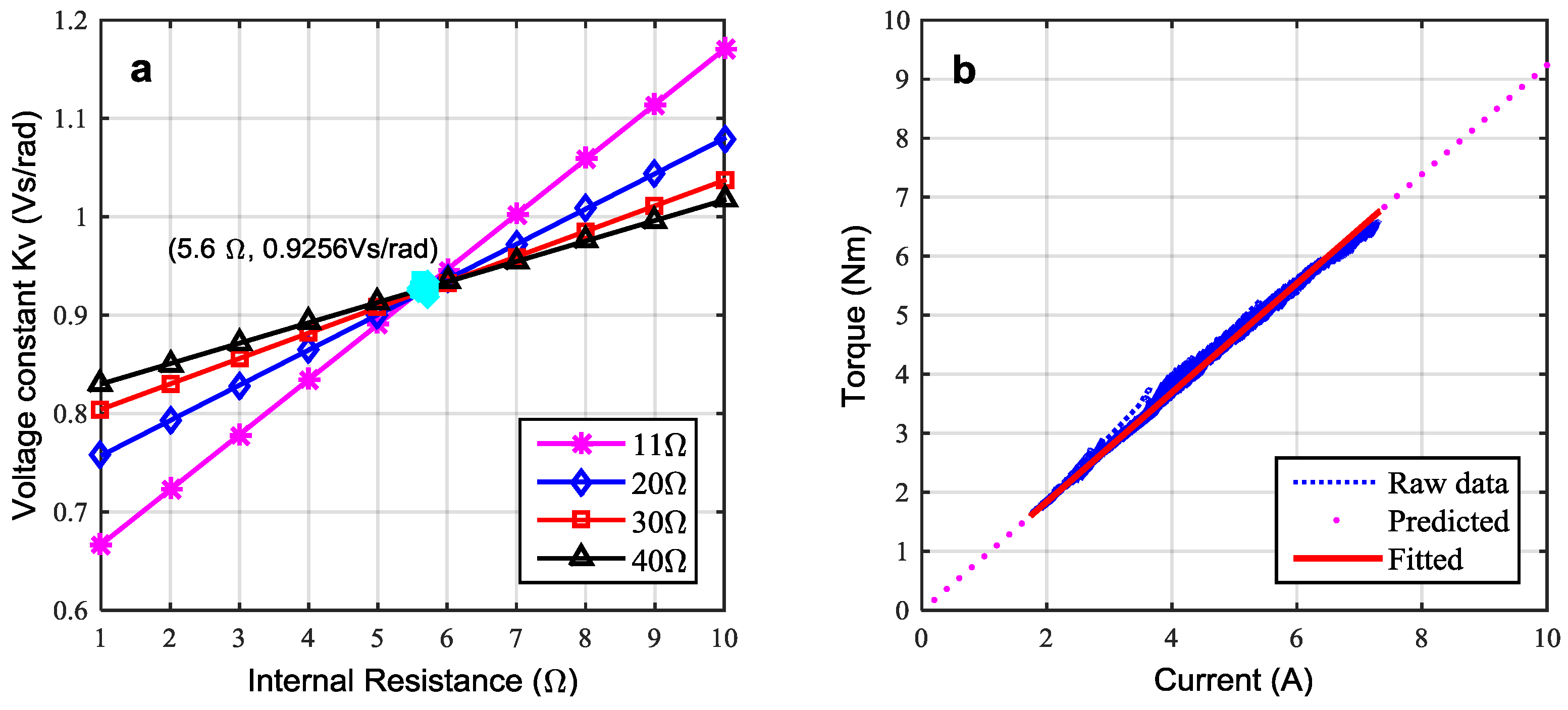
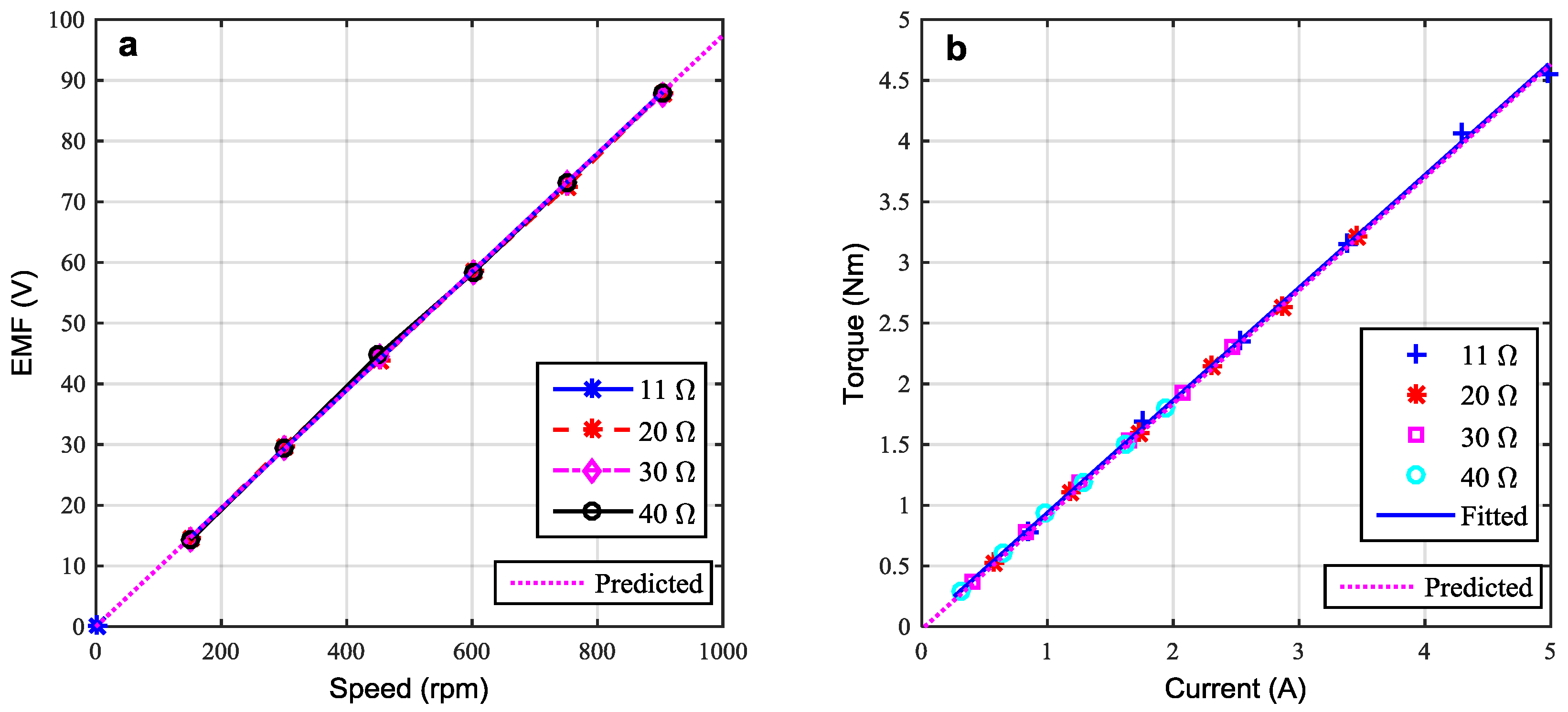
4.1. Power Regeneration System
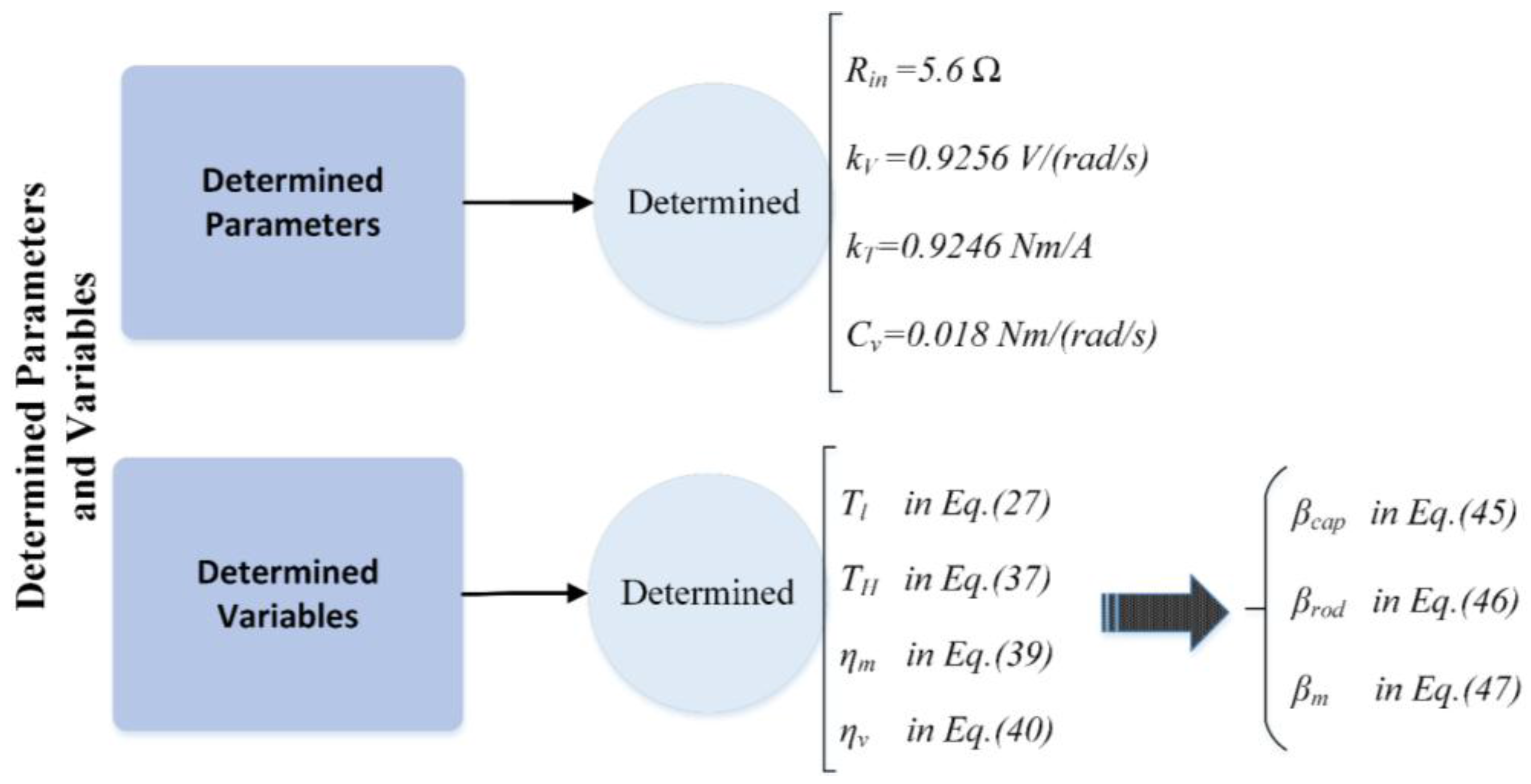
4.2. Hydraulic System
- Firstly, the hydraulic cylinder was assumed to be frictionless and without leakage.
- Secondly, in Equation (20), the mean values of the time-varying pressure and speed of the motor were taken as the nominal pressure drop (for the calculation of the hydraulic motor leakage coefficient) and the nominal shaft speed, respectively.
- Thirdly, the values of kT and kV were used as determined in Section 4.1, meaning that there are no additional electrical losses in the generator model to be accounted for, hence it can be assumed that the hydraulic motor power output Pm is equal to the power captured in the generator Pcap.
5. Results and Discussion
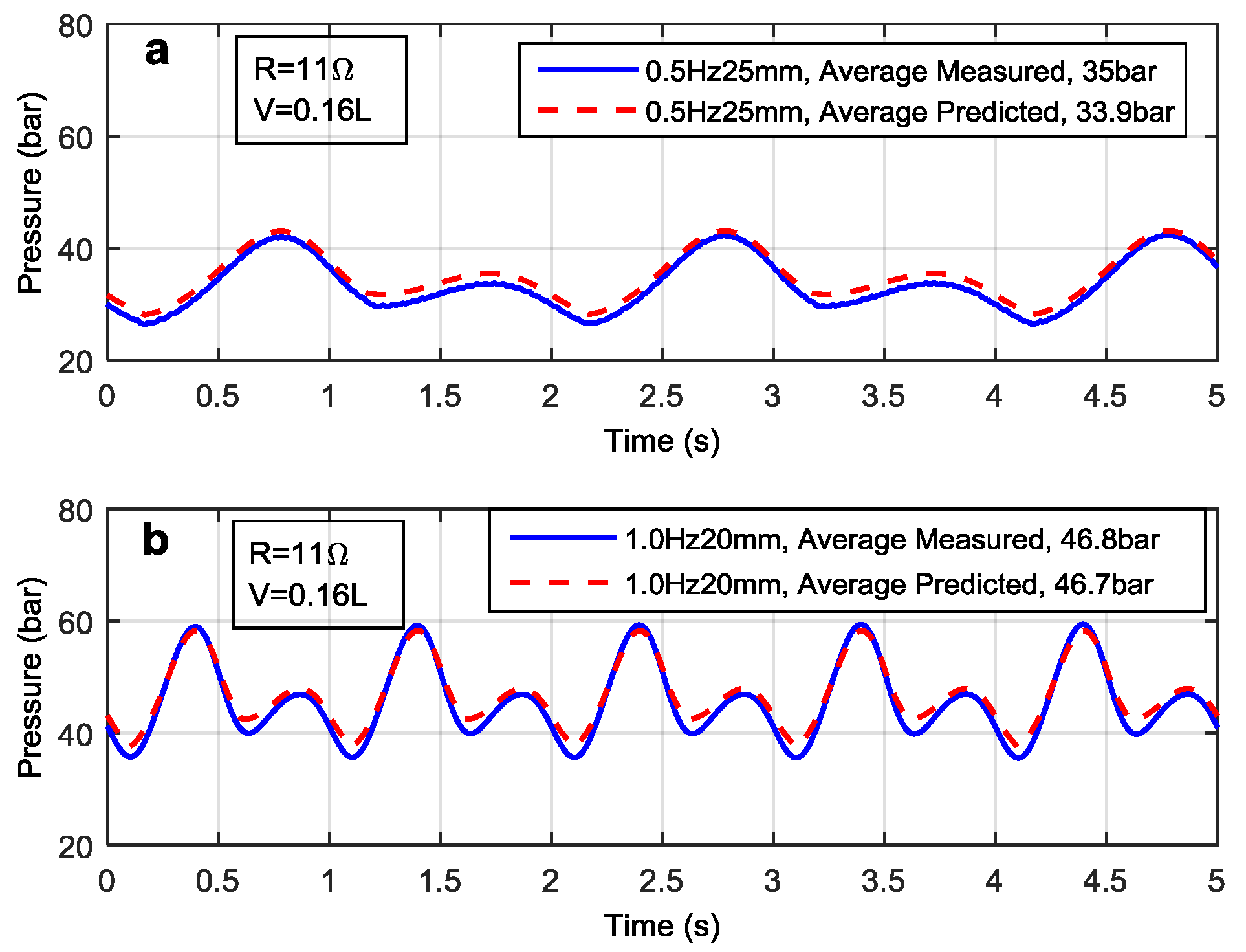
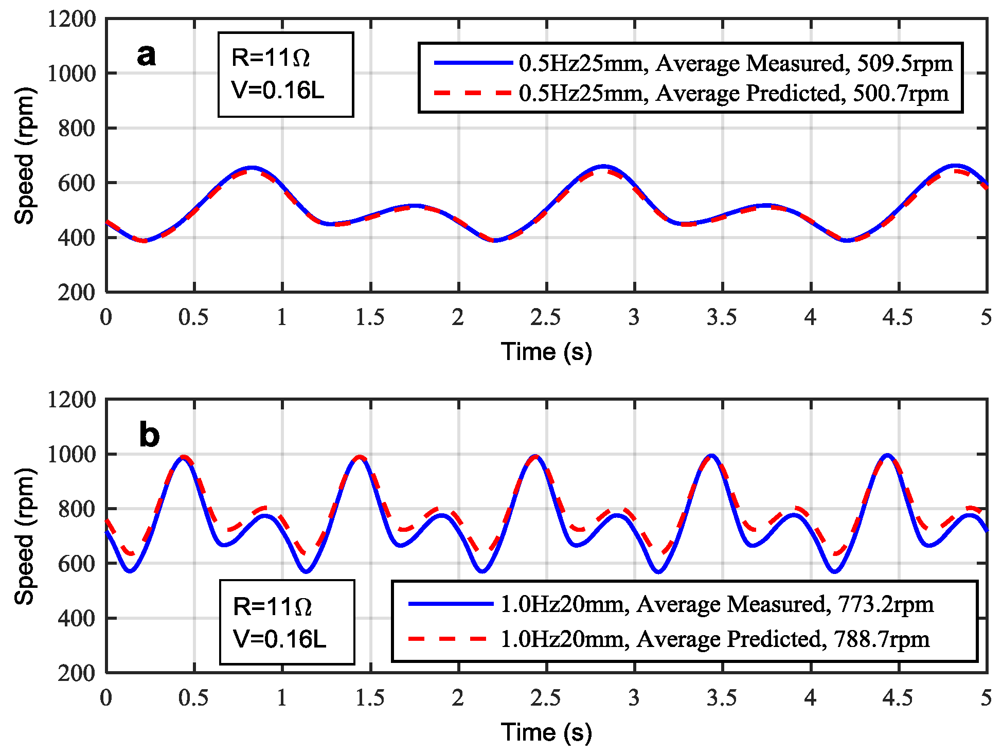
5.1. Validation Using Excitations
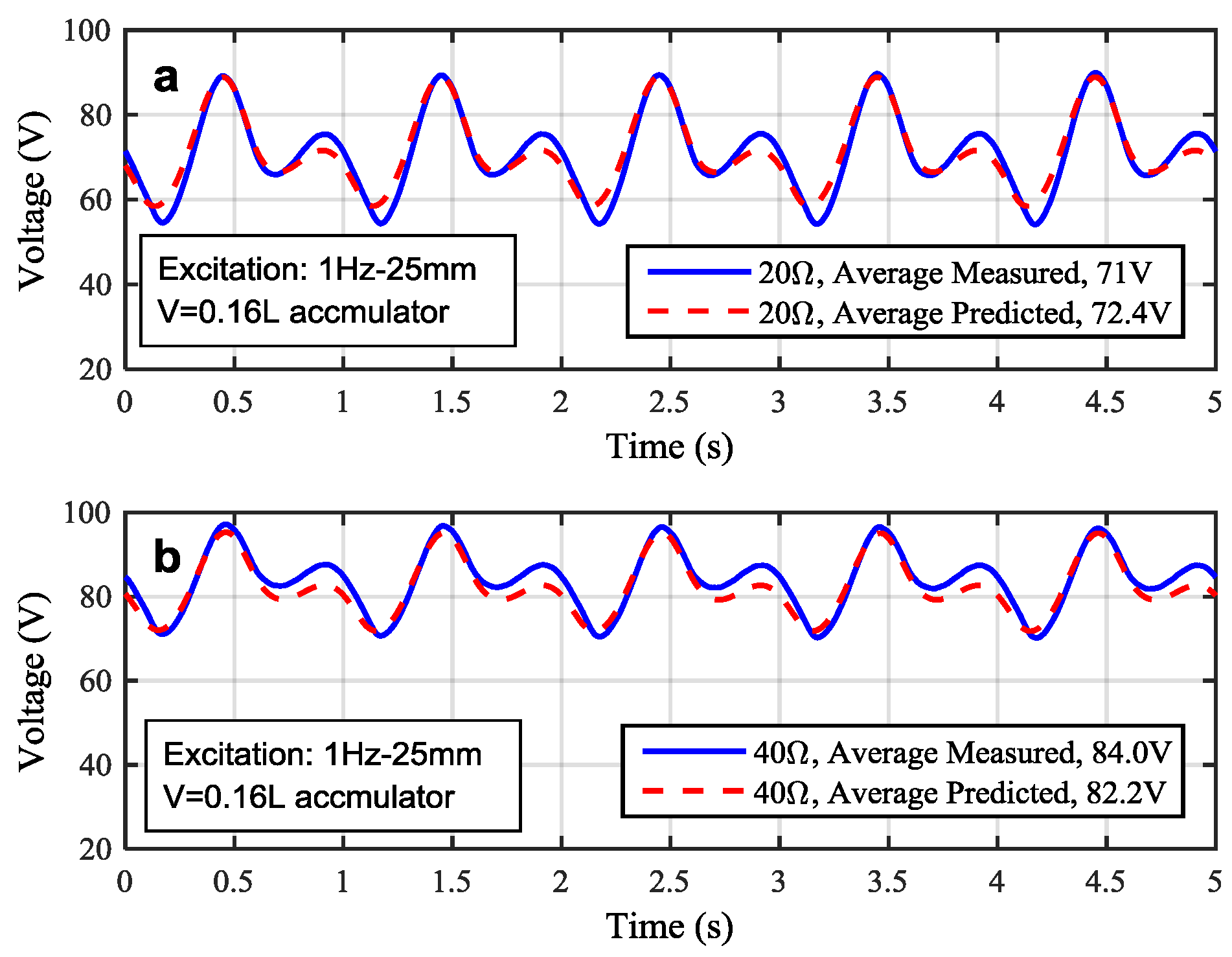
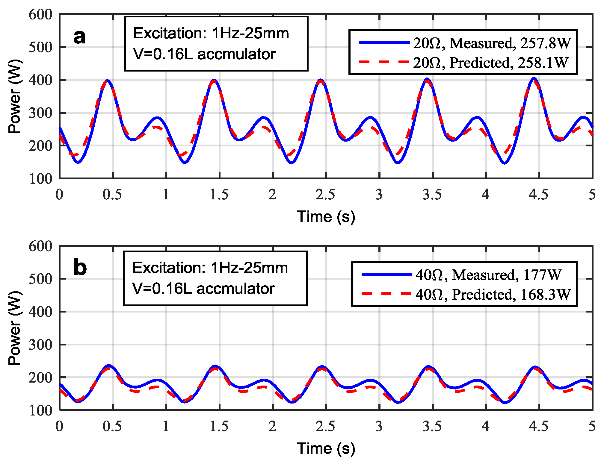
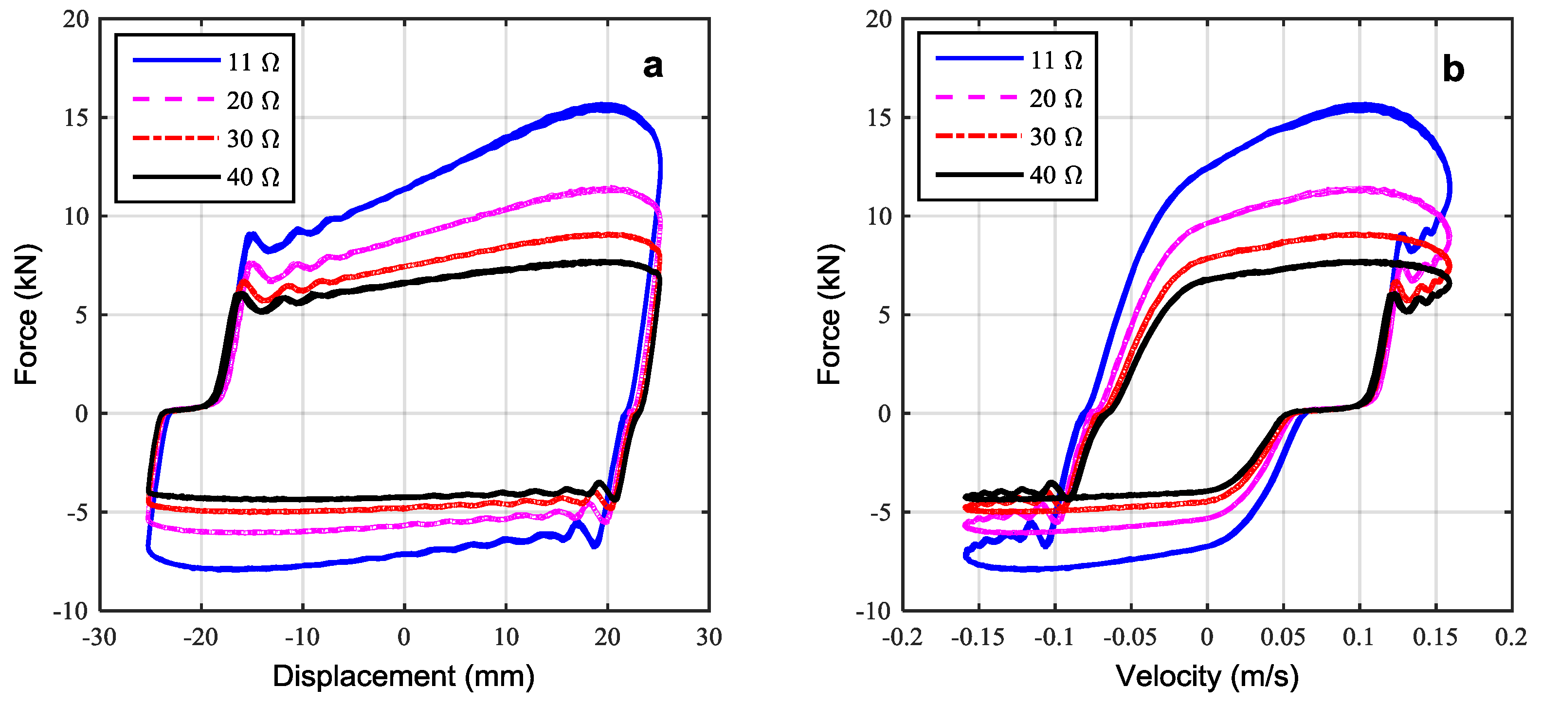
5.2. Validation Using Different Load Resistances
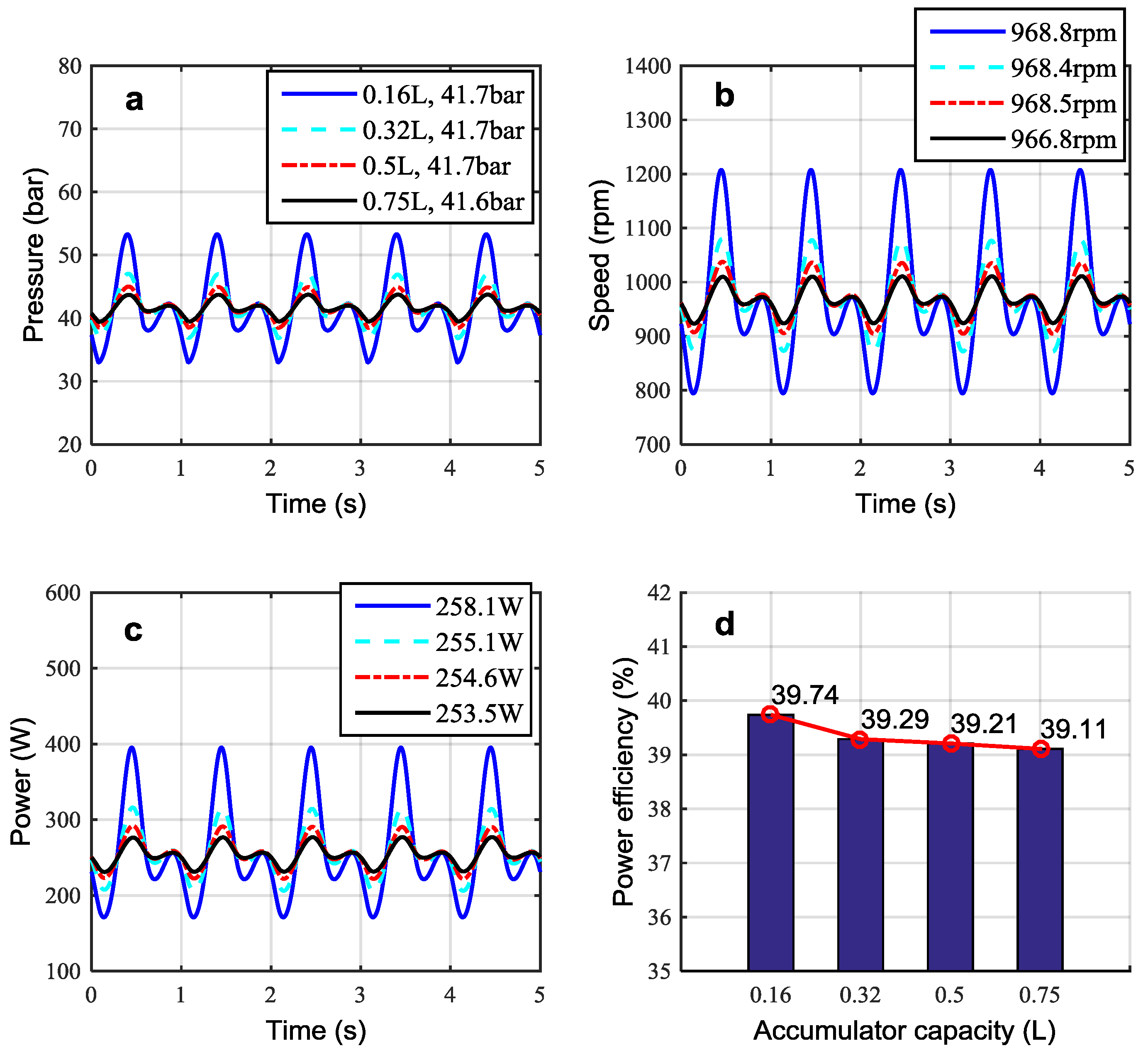
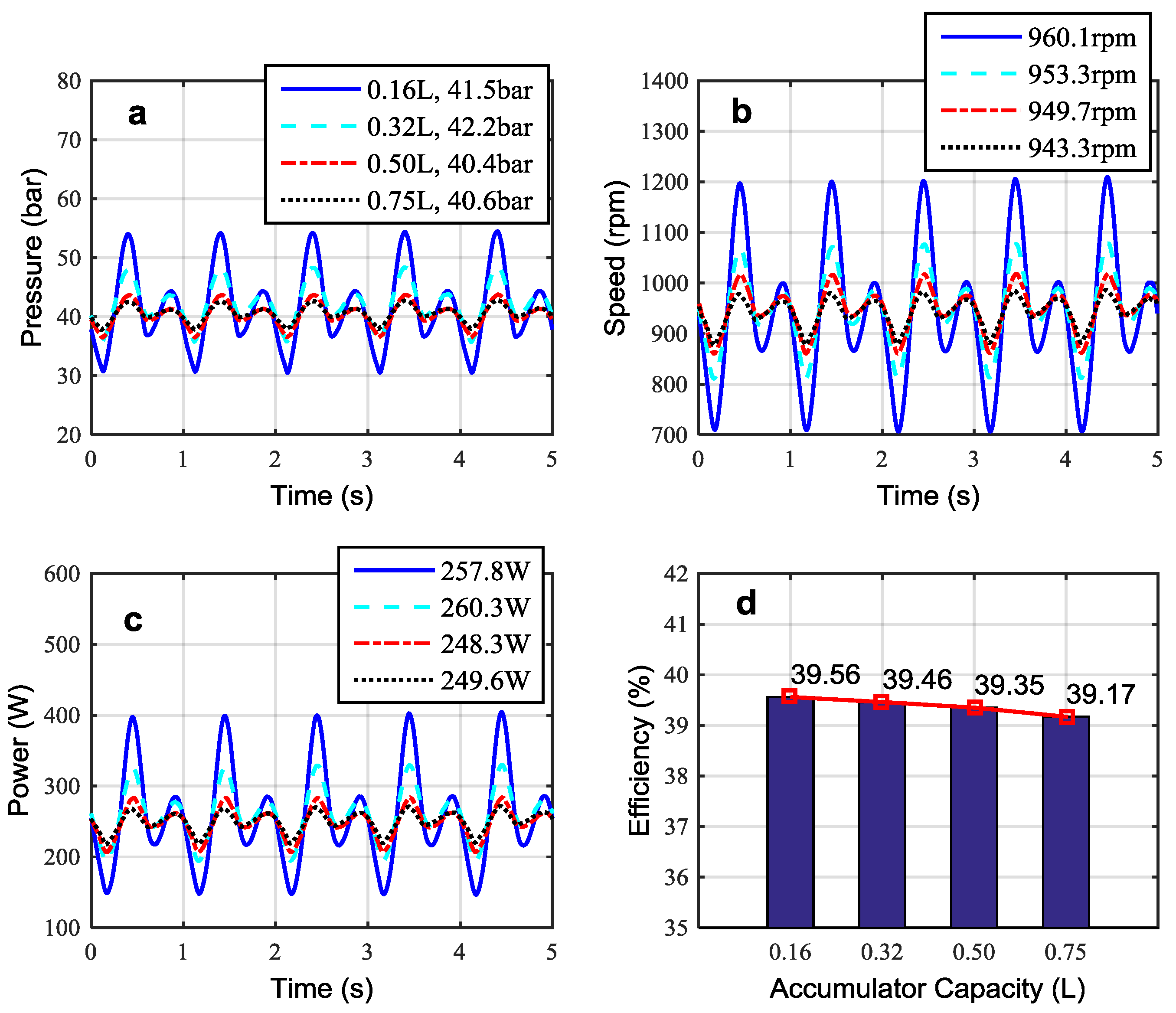
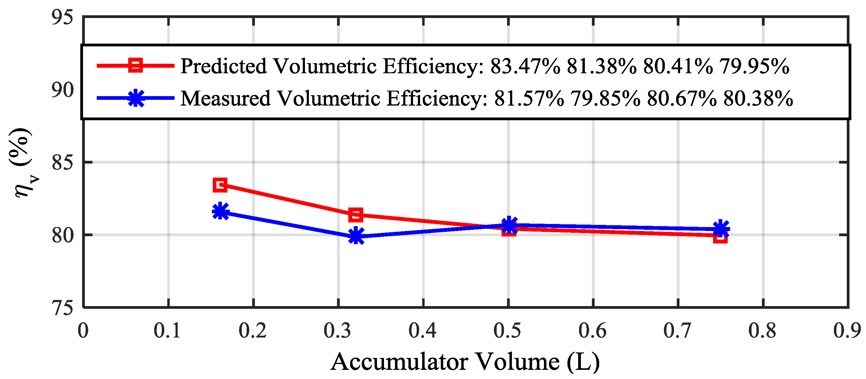
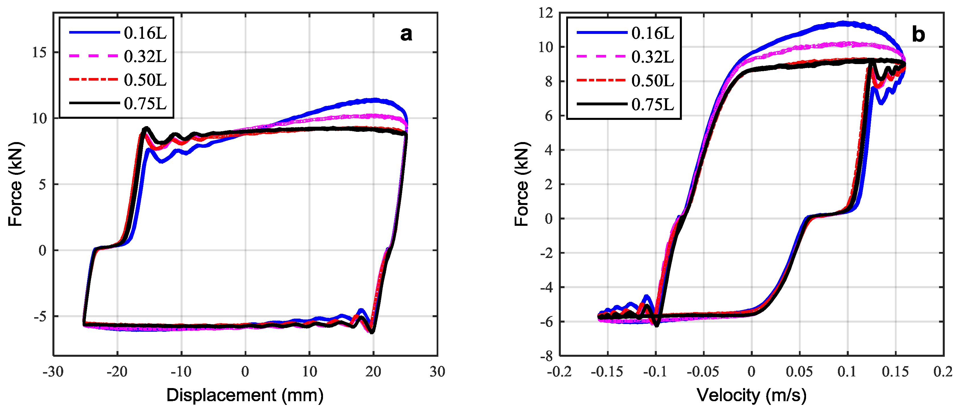
5.3. The effect of Accumulator Capacity
6. Conclusions
Acknowledgments
Author Contributions
Conflicts of Interest
References
- Khan, S.; Stadnyk, S.; Wilkes, E. Official Statistic: Energy Consumption in the UK; Department of Energy & Climate Change: London, UK, 2013.
- Zhang, P.-S. Design of Electromagnetic Shock Absorbers for Energy Harvesting from Vehicle Suspensions. Master’s Thesis, Stony Brook University, Stony Brook, NY, USA, 2010. [Google Scholar]
- Karnopp, D. Power requirements for vehicle suspension systems. Veh. Syst. Dyn. 1992, 21, 65–71. [Google Scholar] [CrossRef]
- Velinsky, S.A.; White, R.A. Vehicle energy dissipation due to road roughness. Veh. Syst. Dyn. 1980, 9, 359–384. [Google Scholar] [CrossRef]
- Segel, L.; Lu, X. Vehicular resistance to motion as influenced by road roughness and highway alignment. Aust. Road Res. 1982, 12, 211–222. [Google Scholar]
- Hsu, P. Power recovery property of electrical active suspension systems. In Proceedings of the 1996 31st Intersociety Energy Conversion Engineering Conference, Washington, DC, USA, 11–16 August 1996; Volume 3, pp. 1899–1904.
- Zuo, L.; Zhang, P.-S. Energy harvesting, ride comfort, and road handling of regenerative vehicle suspensions. J. Vib. Acoust. 2013, 135. [Google Scholar] [CrossRef]
- Zyga, L. Energy harvesting shock absorber technology wins R&D 100 award. Phys. Org. 2011. Available online: http://phys.org/news/2011-07-energy-harvesting-absorber-fuel-efficiency-award.html (accessed on 4 May 2016).
- Li, Z.; Brindak, Z.; Zuo, L. Modeling of an Electromagnetic Vibration Energy Harvester with Motion Magnification. In Proceedings of the ASME 2011 International Mechanical Engineering Congress and Exposition, Denver, CO, USA, 11–17 November 2011; pp. 285–293.
- Kavalchuk, I.; Arisoy, H.; Stojcevski, A.; Than Oo, M.T. Advanced simulation of power consumption of electric vehicles. Electr. Comput. Energ. Electron. Commun. Eng. 2015, 9, 53–59. [Google Scholar]
- Suda, Y.; Nakadai, S.; Nakano, K. Study on the self-powered active vibration control. In Proceedings of the 4th International Conference on Motion and Vibration Control, Zürich, Switzerland, 25–28 August 1998.
- Nakano, K.; Suda, Y.; Nakadai, S. Self-powered active vibration control using continuous control input. JSME Int. J. Ser. C 2000, 43, 726–731. [Google Scholar] [CrossRef]
- Arsem, H.B. Electric Shock Absorber. U.S. Patent US3559027 A, 26 January 1971. [Google Scholar]
- Suda, Y.; Shiiba, T.; Hio, K.; Kawamoto, Y.; Kondo, T.; Yamagata, H. Study on electromagnetic damper for automobiles with nonlinear damping force characteristics: (Road test and theoretical analysis). In Proceedings of the International Association for Vehicle System Dynamics Symposium, Kanagawa, Japan, 24–30 August 2003; Volume 41, pp. 637–646.
- Li, Z.; Zuo, L.; Luhrs, G.; Lin, L.; Qin, Y.X. Electromagnetic energy-harvesting shock absorbers: Design, Modeling, and Road Tests. IEEE Trans. Veh. Technol. 2013, 62, 1065–1074. [Google Scholar] [CrossRef]
- Sabzehgar, R.; Maravandi, A.; Moallem, M. Energy Regenerative Suspension Using an Algebraic Screw Linkage Mechanism. IEEE/ASME Trans. Mechatron. 2014, 19, 1251–1259. [Google Scholar] [CrossRef]
- Avadhany, S.; Abel, P.; Tarasov, V.; Anderson, Z. Regenerative Shock Absorber. U.S. Patent US20090260935 A1, 22 October 2009. [Google Scholar]
- Anderson, Z.; Jackowski, Z.; Bavetta, R. Regenerative Shock Absorber System. U.S. Patent US20100072760 A1, 25 March 2010. [Google Scholar]
- Fang, Z.; Guo, X.; Xu, L.; Zhang, H. Experimental study of damping and energy regeneration characteristics of a hydraulic electromagnetic shock absorber. Adv. Mech. Eng. 2013, 5. [Google Scholar] [CrossRef]
- Fang, Z.; Guo, X.X.; Xu, L.; Zhang, H. An optimal algorithm for energy recovery of hydraulic electromagnetic energy-regenerative shock absorber. Appl. Math. Inf. Sci. 2013, 7, 2207–2214. [Google Scholar] [CrossRef]
- Li, C.P.; Tse, W. Fabrication and testing of an energy-harvesting hydraulic damper. Smart Mater. Struct. 2013, 22. [Google Scholar] [CrossRef]
- Li, C.; Zhu, R.; Liang, M.; Yang, S. Integration of shock absorption and energy harvesting using a hydraulic rectifier. J. Sound Vib. 2014, 333, 3904–3916. [Google Scholar] [CrossRef]
- Zhang, Y.; Zhang, X.; Zhan, M.; Guo, K.; Zhao, F.; Liu, Z. Study on a novel hydraulic pumping regenerative suspension for vehicles. J. Frankl. Inst. 2015, 352, 485–499. [Google Scholar] [CrossRef]
- Zheng, X.; Fan, Y.; Zhang, Y.Z. A novel energy-regenerative active suspension for vehicles. J. Shanghai Jiaotong Univ. Sci. 2008, 13, 184–188. [Google Scholar] [CrossRef]
- Zheng, X.; Yu, F. Study on the potential benefits of an energy-regenerative active suspension for vehicles. SAE Trans. 2005, 114, 242–245. [Google Scholar]
- Lin, X.; Bo, Y.; Xuexun, G.; Jun, Y. Simulation and performance evaluation of hydraulic transmission electromagnetic energy-regenerative active suspension. In Proceedings of the 2010 Second WRI Global Congress on Intelligent Systems (GCIS), Wuhan, China, 16–17 December 2010; Volume 3, pp. 58–61.
- Tucker, C.; Wendell, R.; Anderson, Z.M.; Moen, E.; Schneider, J.; Jackowski, Z.M.; Morton, S. Integrated Energy Generating Damper. EP2582976 A2, 24 April 2013. [Google Scholar]
- Guo, K.; Zhang, Y.; Chen, Y.; Liu, Y. Active Pump Type Energy-Regenerative Damping System. CN103470672 A, 25 December 2013. [Google Scholar]
- Fang, Z.; Guo, X.X. Energy Dissipation and Recovery of Vehicle Shock Absorbers. SAE Tech. Pap. 2012. [Google Scholar] [CrossRef]
- Verros, G.; Natsiavas, S.; Papadimitriou, C. Design optimization of quarter-car models with passive and semi-active suspensions under random road excitation. J. Vib. Control 2005, 11, 581–606. [Google Scholar] [CrossRef]
- Armstrong-Hélouvry, B.; Dupont, P.; De Wit, C.C. A survey of models, analysis tools and compensation methods for the control of machines with friction. Automatica 1994, 30, 1083–1138. [Google Scholar] [CrossRef]
- Hamzehlouia, S.; Izadian, A.; Pusha, A.; Anwar, S. Controls of hydraulic wind power transfer. In Proceedings of the 37th Annual Conference on IEEE Industrial Electronics Society (IECON 2011), Melbourne, Australia, 7–10 November 2011; pp. 2475–2480.
- Crowe, C.T.; Elger, D.F.; Roberson, J.A. Engineering Fluid Mechanics; Wiley: Hoboken, NJ, USA, 2005. [Google Scholar]
- Franklin, G.F.; Powell, J.D.; Emami-Naeini, A. Feedback Control of Dynamic Systems; Pearson: London, UK, 2010. [Google Scholar]
- Mossberg, J.; Anderson, Z.; Turker, C.; Schneider, J. Recovering Energy from Shock Absorber Motion on Heavy Duty Commercial Vehicles. SAE Tech. Pap. 2012. [Google Scholar] [CrossRef]
- Wang, R.; Chen, Z.; Xu, H.; Schmidt, K.; Gu, F.; Ball, A.D. Modelling and validation of a regenerative shock absorber system. In Proceedings of the 20th International Conference on Automation and Computing (ICAC’14), Cranfield, UK, 12–13 September 2014; pp. 32–37.
- ISO 8608:1995. Mechanical Vibration. Road Surface Profiles: Reporting of Measured Data; International Organization for Standardization: Geneva, Switzerland, 1996. [Google Scholar]
- Pan, L.; Wu, L. A hybrid global optimization method for inverse estimation ofhydraulic parameters: Annealing-simplex method. Water Resour. Res. 1998, 34, 2261–2269. [Google Scholar] [CrossRef]
- Backe, W.; Murrenhoff, H. Fundamentals of Hydraulic Oil Lecture Notes: Institute for Fluid Power Drives and Controls; RWTH Aachen University: Aachen, Germany, 1994. [Google Scholar]
- Boes, C. Hydraulische Achsantriebe im Digitalen Regelkreis. Ph.D. Thesis, RWTH Aachen University, Aachen, Germany, 1995. [Google Scholar]


| Name | Specification | ||
|---|---|---|---|
| Cylinder | Middle point, S0 = 100 mm, Full stroke, 200 mm | Piston area, Dcap = 50 mm, Annulus area, Drod = 30 mm | Max. pressure, 200 bar |
| Motor | Displacement, Dm = 8.2 cc (cm3/rev) | Max. speed, 245 rad/s | Max. power, <6000 W |
| Generator | Internal inductance, Lin = 0.015 H | 2.33 Phase magnetic field, Built in rectifier, Max. speed, 215 rad/s | Max. current, 10 A, Max. power, <2450 W |
| Accumulator | Diaphragm accumulator | Port diameter, Dacc = 12.7 mm | Pre-charge pressure, Ppc = 20 bar |
| Check Valve | Diameter: 3/8′ (≈9.525 mm), BSPP | Max. pressure, 350 bar | Preload pressure, Pcv = 0.7 bar |
| Four Post Simulator | Maximum velocity, 1.9 m/s | Static load, 550 kg | Preload, 60 kg |
| Hose | Hose diameter, Dh = 3/8′ | Length, L = 1 m | Max. pressure, 800 bar |
| Shock Absorber Oil | Density, ρ = 872 kg/m3 | Viscosity, σ = 22 cSt | - |
| Name | Symbol | Value | Unit | Name | Symbol | Value | Unit |
|---|---|---|---|---|---|---|---|
| Accumulator inlet area | Aacc | 1.27 × 10⁻⁴ | m2 | Flow coefficient | Cq | 0.7 | - |
| Full piston face area | Acap | 1.96 × 10⁻³ | m2 | Specific heat ratio | k | 1.4 | - |
| Check valve area | Acv | 3.93 × 10⁻⁵ | m2 | Cylinder dead volume | Vcyd | 1 × 10⁻⁸ | m3 |
| Pipe area | Ap | 7.85 × 10⁻⁵ | m2 | Accumulator dead volume * | Vagd | 1%∙Vc | m3 |
| Annular area of piston | Arod | 1.26 × 10⁻³ | m2 | Initial volume of cap-end chamber | Vic | 3.93 × 10⁻⁴ | m3 |
| Discharge coefficient | Cd | 0.7 | - | Initial volume of rod-end chamber | Vrc | 6.38 × 10⁻⁴ | m3 |
© 2016 by the authors; licensee MDPI, Basel, Switzerland. This article is an open access article distributed under the terms and conditions of the Creative Commons Attribution (CC-BY) license (http://creativecommons.org/licenses/by/4.0/).
Share and Cite
Wang, R.; Gu, F.; Cattley, R.; Ball, A.D. Modelling, Testing and Analysis of a Regenerative Hydraulic Shock Absorber System. Energies 2016, 9, 386. https://0-doi-org.brum.beds.ac.uk/10.3390/en9050386
Wang R, Gu F, Cattley R, Ball AD. Modelling, Testing and Analysis of a Regenerative Hydraulic Shock Absorber System. Energies. 2016; 9(5):386. https://0-doi-org.brum.beds.ac.uk/10.3390/en9050386
Chicago/Turabian StyleWang, Ruichen, Fengshou Gu, Robert Cattley, and Andrew D. Ball. 2016. "Modelling, Testing and Analysis of a Regenerative Hydraulic Shock Absorber System" Energies 9, no. 5: 386. https://0-doi-org.brum.beds.ac.uk/10.3390/en9050386