Rapid Alloy Development of Extremely High-Alloyed Metals Using Powder Blends in Laser Powder Bed Fusion

 , , and
Abstract
:1. Introduction
2. Materials and Methods
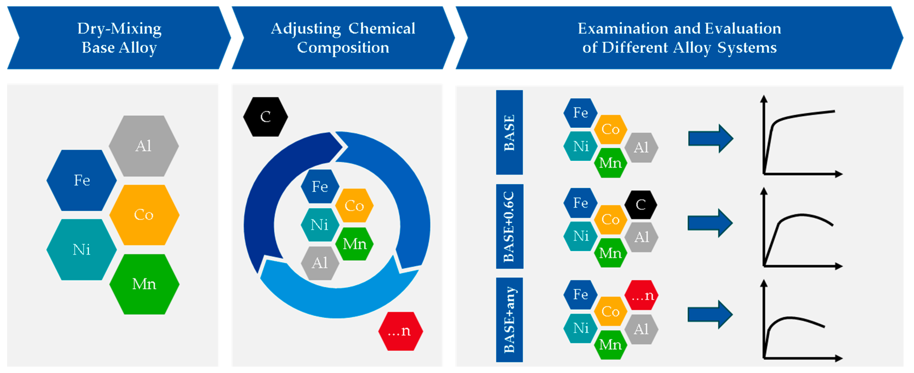
2.1. Rapid Alloy Development Methodology Using Powder Blends in LPBF
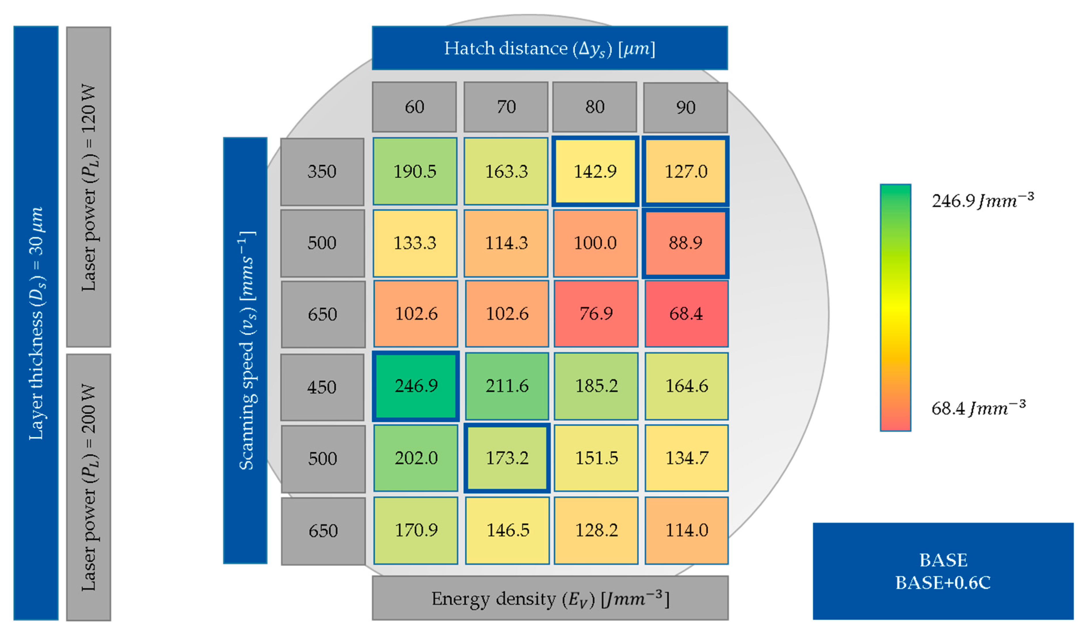
2.2. LPBF Processing
2.3. Sample Preparation and Characterization Techniques
3. Results
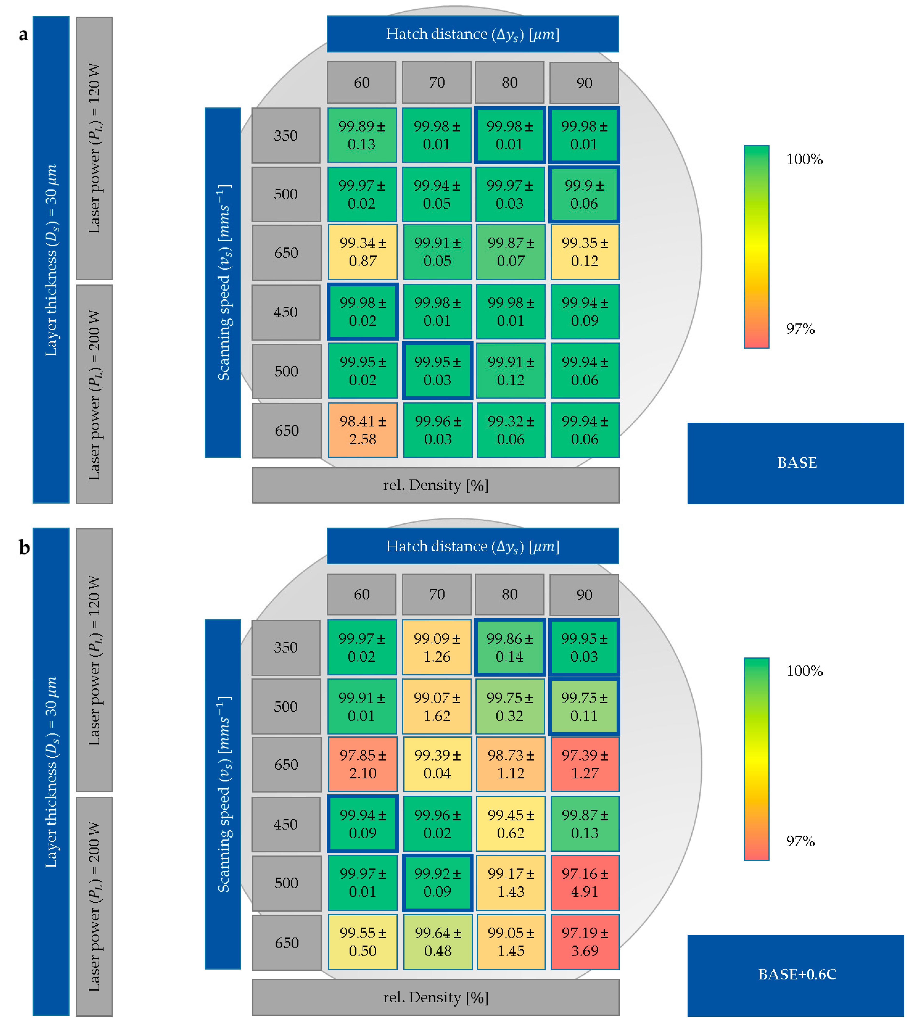
3.1. Process Development
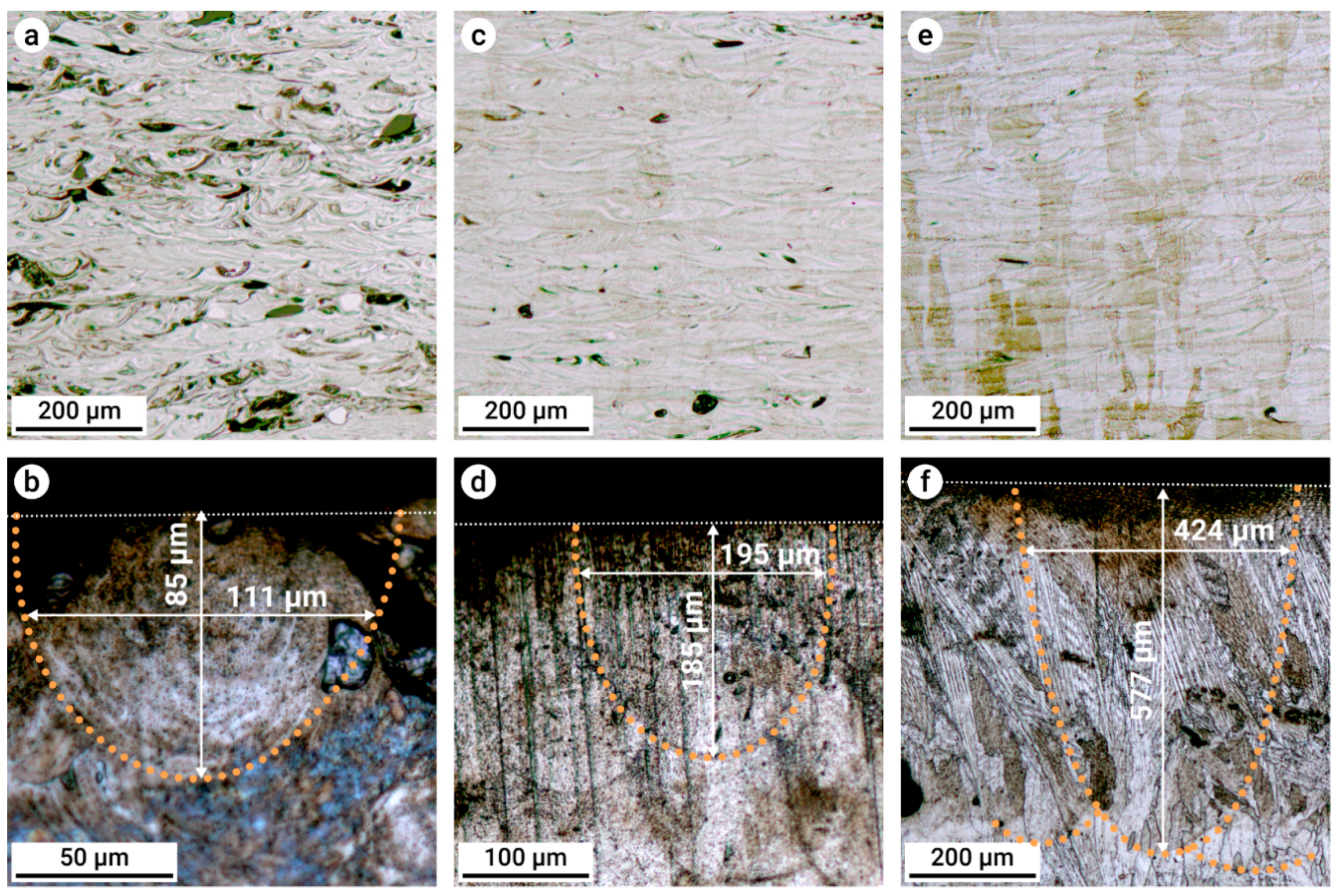
3.2. Meltpool Size Depending on the Energy Input
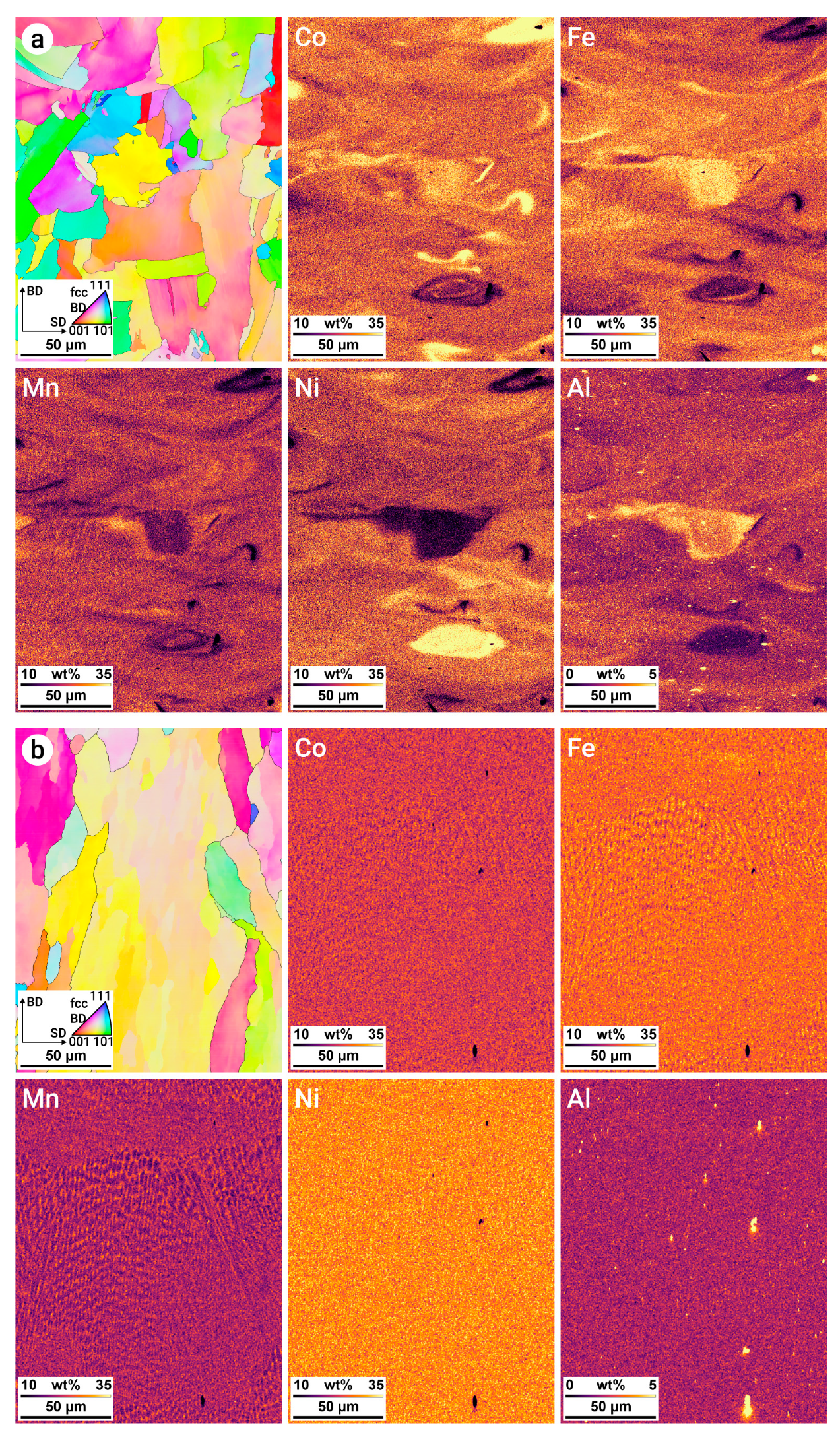
3.3. Chemical Homogeneity
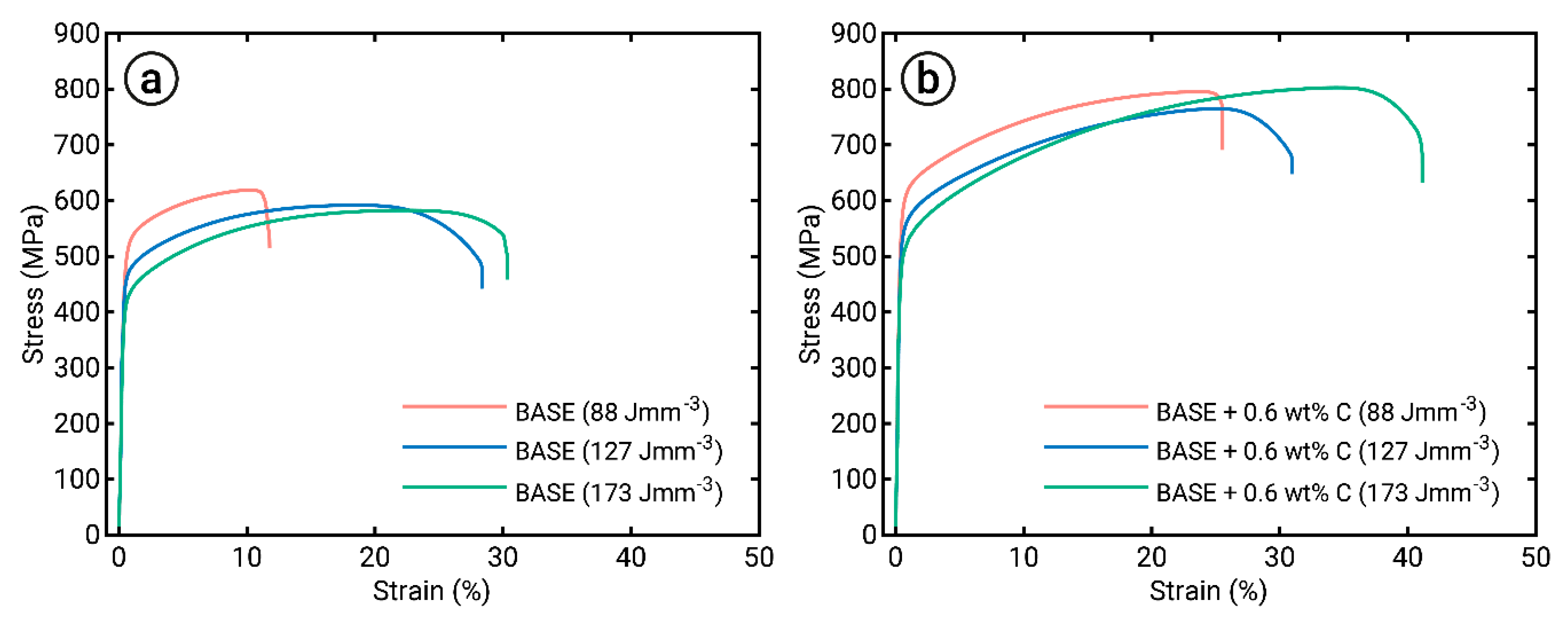
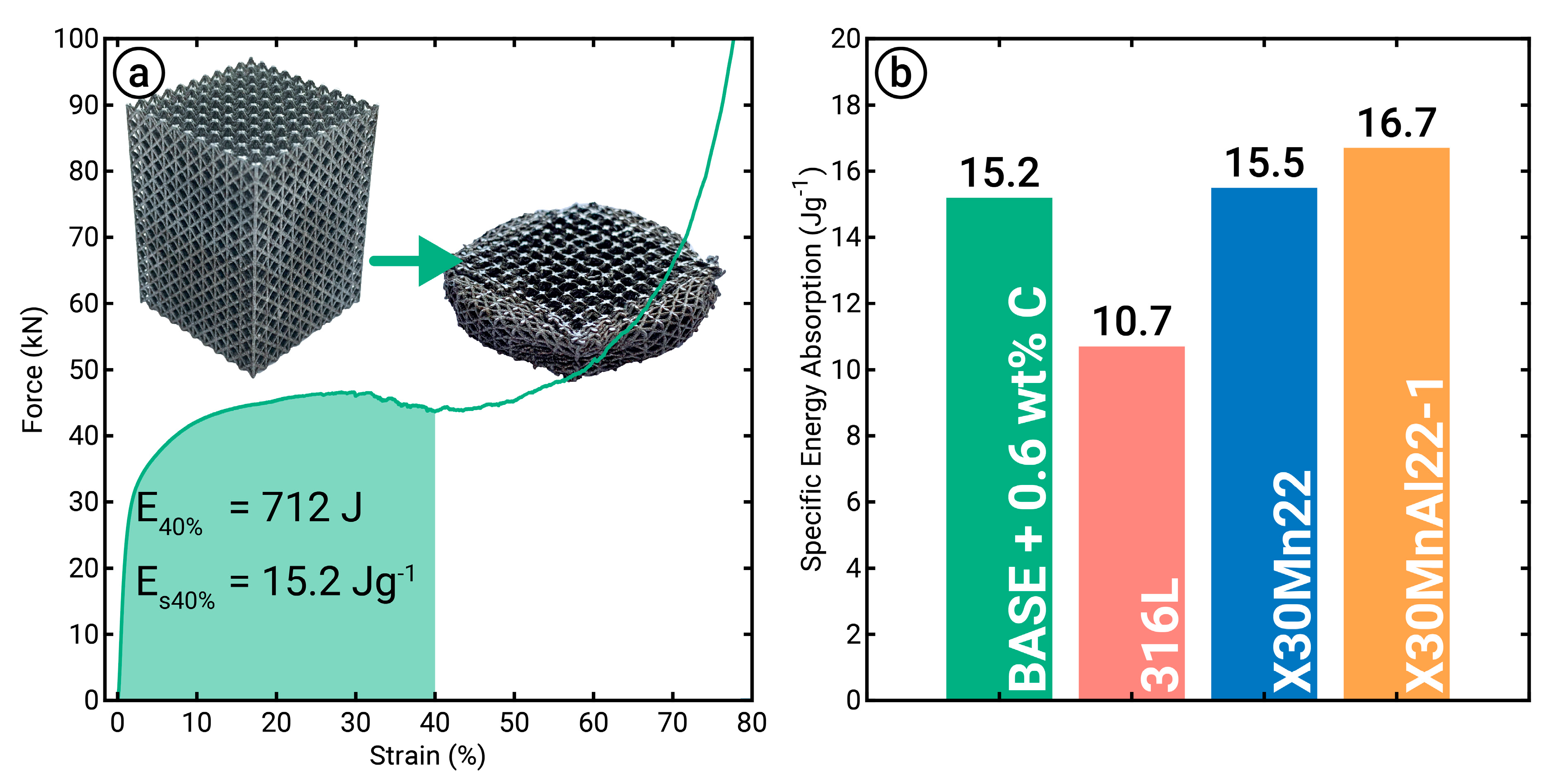
3.4. Mechanical Properties
4. Discussion
5. Conclusions
- Complex powder blends consisting of up to six elemental powders with different morphologies, size distributions, and amounts could be applied to the LPBF process. Therefore, rapid alloy development of chemically complex metallic alloys is possible, which was demonstrated on C-Al-Co-Fe-Mn-Ni MPEAs. Compared to other metal AM processes, higher cooling rates facilitated improved material properties, e.g., high strength, high energy absorption capacity, and less elemental segregation.
- Chemical homogeneity was strongly dependent on the energy input and resulting size of the melt pool formed during LPBF. On the one hand, insufficient energy input resulted in inhomogeneous elemental distribution, as powders with high melting points were only partially melted. On the other hand, small melt pool sizes prohibited sufficient elemental mixing. Optimal energy input resulted in alloys with high chemical homogeneity.
- The mechanical properties of the investigated Al0.26CoFeMnNi system were significantly improved by the addition of 0.6 wt% C, resulting in both increased strength and ductility. Therefore, the methodology of combining powder blending and LPBF was proven to be a promising method to produce high-quality material containing significant nonmetallic additions, such as C.
- LPBF using powder blends enables manufacturing of parts with complex geometry, e.g., lattice structures, and reliable mechanical properties. The produced lattice structures indicated a higher energy absorption capacity compared to the commonly used 316L and were comparable to high-Manganese steel samples.
Author Contributions
Funding
Conflicts of Interest
References
- Gibson, I.; Rosen, D.W.; Stucker, B. Additive Manufacturing Technologies; Springer US: Boston, MA, USA, 2010; ISBN 978-1-4419-1119-3. [Google Scholar]
- Schleifenbaum, H.; Meiners, W.; Wissenbach, K.; Hinke, C. Individualized production by means of high power Selective Laser Melting. CIRP J. Manuf. Sci. Technol. 2010, 2, 161–169. [Google Scholar] [CrossRef]
- Wen, P.; Jauer, L.; Voshage, M.; Chen, Y.; Poprawe, R.; Schleifenbaum, J.H. Densification behavior of pure Zn metal parts produced by selective laser melting for manufacturing biodegradable implants. J. Mater. Process. Technol. 2018, 258, 128–137. [Google Scholar] [CrossRef]
- Haase, C.; Bültmann, J.; Hof, J.; Ziegler, S.; Bremen, S.; Hinke, C.; Schwedt, A.; Prahl, U.; Bleck, W. Exploiting Process-Related Advantages of Selective Laser Melting for the Production of High-Manganese Steel. Materials (Basel) 2017, 10, 56. [Google Scholar] [CrossRef] [PubMed]
- Kundin, J.; Ramazani, A.; Prahl, U.; Haase, C. Microstructure Evolution of Binary and Multicomponent Manganese Steels During Selective Laser Melting: Phase-Field Modeling and Experimental Validation. Metall. Mater. Trans. A 2019, 50, 2022–2040. [Google Scholar] [CrossRef]
- Zhang, L.-C.; Attar, H. Selective Laser Melting of Titanium Alloys and Titanium Matrix Composites for Biomedical Applications: A Review. Adv. Eng. Mater. 2016, 18, 463–475. [Google Scholar] [CrossRef]
- Gu, D.; Hagedorn, Y.-C.; Meiners, W.; Wissenbach, K.; Poprawe, R. Nanocrystalline TiC reinforced Ti matrix bulk-form nanocomposites by Selective Laser Melting (SLM): Densification, growth mechanism and wear behavior. Compos. Sci. Technol. 2011, 71, 1612–1620. [Google Scholar] [CrossRef]
- Chen, Y.; Zhang, J.; Dai, N.; Qin, P.; Attar, H.; Zhang, L.-C. Corrosion Behaviour of Selective Laser Melted Ti-TiB Biocomposite in Simulated Body Fluid. Electrochim. Acta 2017, 232, 89–97. [Google Scholar] [CrossRef] [Green Version]
- Cantor, B.; Chang, I.T.H.; Knight, P.; Vincent, A.J.B. Microstructural development in equiatomic multicomponent alloys. Mater. Sci. Eng. A 2004, 375–377, 213–218. [Google Scholar] [CrossRef]
- Gao, M.C.; Yeh, J.-W.; Liaw, P.K.; Zhang, Y. High-Entropy Alloys; Springer International Publishing: Cham, Switzerland, 2016; ISBN 978-3-319-27011-1. [Google Scholar]
- Yeh, J.-W. Alloy Design Strategies and Future Trends in High-Entropy Alloys. JOM 2013, 65, 1759–1771. [Google Scholar] [CrossRef]
- Miracle, D.B.; Senkov, O.N. A critical review of high entropy alloys and related concepts. Acta Mater. 2017, 122, 448–511. [Google Scholar] [CrossRef] [Green Version]
- Haase, C.; Barrales-Mora, L.A. Influence of deformation and annealing twinning on the microstructure and texture evolution of face-centered cubic high-entropy alloys. Acta Mater. 2018, 150, 88–103. [Google Scholar] [CrossRef] [Green Version]
- Haase, C.; Tang, F.; Wilms, M.B.; Weisheit, A.; Hallstedt, B. Combining thermodynamic modeling and 3D printing of elemental powder blends for high-throughput investigation of high-entropy alloys—Towards rapid alloy screening and design. Mater. Sci. Eng. A 2017, 688, 180–189. [Google Scholar] [CrossRef]
- Gasser, A.; Backes, G.; Kelbassa, I.; Weisheit, A.; Wissenbach, K. Laser Additive Manufacturing. LTJ 2010, 7, 58–63. [Google Scholar] [CrossRef]
- Ewald, S.; Schaukellis, M.; Koehnen, P.; Schleifenbaum, J.H. Laser Powder Bed Fusion of Advanced High-Strength Steels—Modification of Deformation Mechanisms by Increasing Stacking Fault Energy. BHM Berg 2019, 10, 2. [Google Scholar] [CrossRef]
- Liu, Z.H.; Zhang, D.Q.; Sing, S.L.; Chua, C.K.; Loh, L.E. Interfacial characterization of SLM parts in multi-material processing: Metallurgical diffusion between 316L stainless steel and C18400 copper alloy. Mater. Charact. 2014, 94, 116–125. [Google Scholar] [CrossRef]
- Kies, F.; Köhnen, P.; Wilms, M.B.; Brasche, F.; Pradeep, K.G.; Schwedt, A.; Richter, S.; Weisheit, A.; Schleifenbaum, J.H.; Haase, C. Design of high-manganese steels for additive manufacturing applications with energy-absorption functionality. Mater. Des. 2018, 160, 1250–1264. [Google Scholar] [CrossRef]
- Li, W.; Chen, X.; Yan, L.; Zhang, J.; Zhang, X.; Liou, F. Additive manufacturing of a new Fe-Cr-Ni alloy with gradually changing compositions with elemental powder mixes and thermodynamic calculation. Int. J. Adv. Manuf. Technol. 2018, 95, 1013–1023. [Google Scholar] [CrossRef]
- Meiners, W. Direktes Selektives Laser Sintern Einkomponentiger Metallischer Werkstoffe. (Direct Laser Sintering of Single-Component Metallic Materials). Ph.D. Thesis, RWTH Aachen, Aachen, Germany, 1999. [Google Scholar]
- Merkt, S.; Hinke, C.; Bültmann, J.; Brandt, M.; Xie, Y.M. Mechanical response of TiAl6V4 lattice structures manufactured by selective laser melting in quasistatic and dynamic compression tests. J. Laser Appl. 2015, 27, S17006. [Google Scholar] [CrossRef]
- Bachmann, F.; Hielscher, R.; Schaeben, H. Grain detection from 2d and 3d EBSD data--specification of the MTEX algorithm. Ultramicroscopy 2011, 111, 1720–1733. [Google Scholar] [CrossRef]
- Nolze, G.; Hielscher, R. Orientations—Perfectly colored. J. Appl. Crystallogr. 2016, 49, 1786–1802. [Google Scholar] [CrossRef]
- Ashby, M.F. The properties of foams and lattices. Philos. Trans. A Math. Phys. Eng. Sci. 2006, 364, 15–30. [Google Scholar] [CrossRef]
- Tancogne-Dejean, T.; Spierings, A.B.; Mohr, D. Additively-manufactured metallic micro-lattice materials for high specific energy absorption under static and dynamic loading. Acta Mater. 2016, 116, 14–28. [Google Scholar] [CrossRef]
- Köhnen, P.; Haase, C.; Bültmann, J.; Ziegler, S.; Schleifenbaum, J.H.; Bleck, W. Mechanical properties and deformation behavior of additively manufactured lattice structures of stainless steel. Mater. Des. 2018, 145, 205–217. [Google Scholar] [CrossRef]
- Yap, C.Y.; Chua, C.K.; Dong, Z.L.; Liu, Z.H.; Zhang, D.Q.; Loh, L.E.; Sing, S.L. Review of selective laser melting: Materials and applications. Appl. Phys. Rev. 2015, 2, 41101. [Google Scholar] [CrossRef]
- Gu, D. Laser Additive Manufacturing of High-Performance Materials; Springer: Berlin/Heidelberg, Germany, 2015; ISBN 978-3-662-46088-7. [Google Scholar]
- Marchese, G.; Garmendia Colera, X.; Calignano, F.; Lorusso, M.; Biamino, S.; Minetola, P.; Manfredi, D. Characterization and Comparison of Inconel 625 Processed by Selective Laser Melting and Laser Metal Deposition. Adv. Eng. Mater. 2017, 19, 1600635. [Google Scholar] [CrossRef]
- Calleja, A.; Tabernero, I.; Ealo, J.A.; Campa, F.J.; Lamikiz, A.; Lopez de Lacalle, L.N. Feed rate calculation algorithm for the homogeneous material deposition of blisk blades by 5-axis laser cladding. Int. J. Adv. Manuf. Technol. 2014, 74, 1219–1228. [Google Scholar] [CrossRef]
- Frazier, W.E. Metal Additive Manufacturing: A Review. J. Mater. Eng. Perform. 2014, 23, 1917–1928. [Google Scholar] [CrossRef]
- Hebert, R.J. Viewpoint: Metallurgical aspects of powder bed metal additive manufacturing. J. Mater. Sci. 2016, 51, 1165–1175. [Google Scholar] [CrossRef]
- Heeling, T.; Cloots, M.; Wegener, K. Melt pool simulation for the evaluation of process parameters in selective laser melting. Addit. Manuf. 2017, 14, 116–125. [Google Scholar] [CrossRef]
- Holleman, A.F.; Wiberg, E.; Wiberg, N. Lehrbuch der Anorganischen Chemie (Textbook of Chemistry); Walter de Gruyter: Berlin, Germany, 1985; ISBN 3110075113. [Google Scholar]
- Marakushev, A.A.; Bezmen, N.I. Chemical affinity of metals for oxygen and sulfur. Int. Geol. Rev. 2009, 13, 1781–1794. [Google Scholar] [CrossRef]
- Makoana, N.; Yadroitsava, I.; Möller, H.; Yadroitsev, I. Characterization of 17-4PH Single Tracks Produced at Different Parametric Conditions towards Increased Productivity of LPBF Systems—The Effect of Laser Power and Spot Size Upscaling. Metals 2018, 8, 475. [Google Scholar] [CrossRef]
- Gottstein, G. Materialwissenschaft und Werkstofftechnik (Material Science and Engineering); Springer: Berlin/Heidelberg, Germany, 2014; ISBN 978-3-642-36602-4. [Google Scholar]
- Voshage, M.; Wen, P.; Schaukellis, M.; Schleifenbaum, J.H. Formation Quality, Mechanical Properties, and Processing Behavior of Pure Zinc Parts Produced by Laser-Based Manufacturing for Biodegradable Implants. BHM Berg. 2019, 87, 1. [Google Scholar] [CrossRef]
- Xu, Z.; Wen, W.; Zhai, T. Effects of Pore Position in Depth on Stress/Strain Concentration and Fatigue Crack Initiation. Metall. Mat. Trans. A 2012, 43, 2763–2770. [Google Scholar] [CrossRef]
- Rehme, O. Cellular Design for Laser Freeform Fabrication, 1st ed.; Cuvillier Verlag: Göttingen, Germany, 2010; ISBN 9783736932739. [Google Scholar]


| Powder | Manufacturing Method | Particle Size Distribution (μm) | Form | Flowability as Avalanche Angle (°) | Laser Absorption for 1064 nm (%) | Bulk Density (g·ml−1) |
|---|---|---|---|---|---|---|
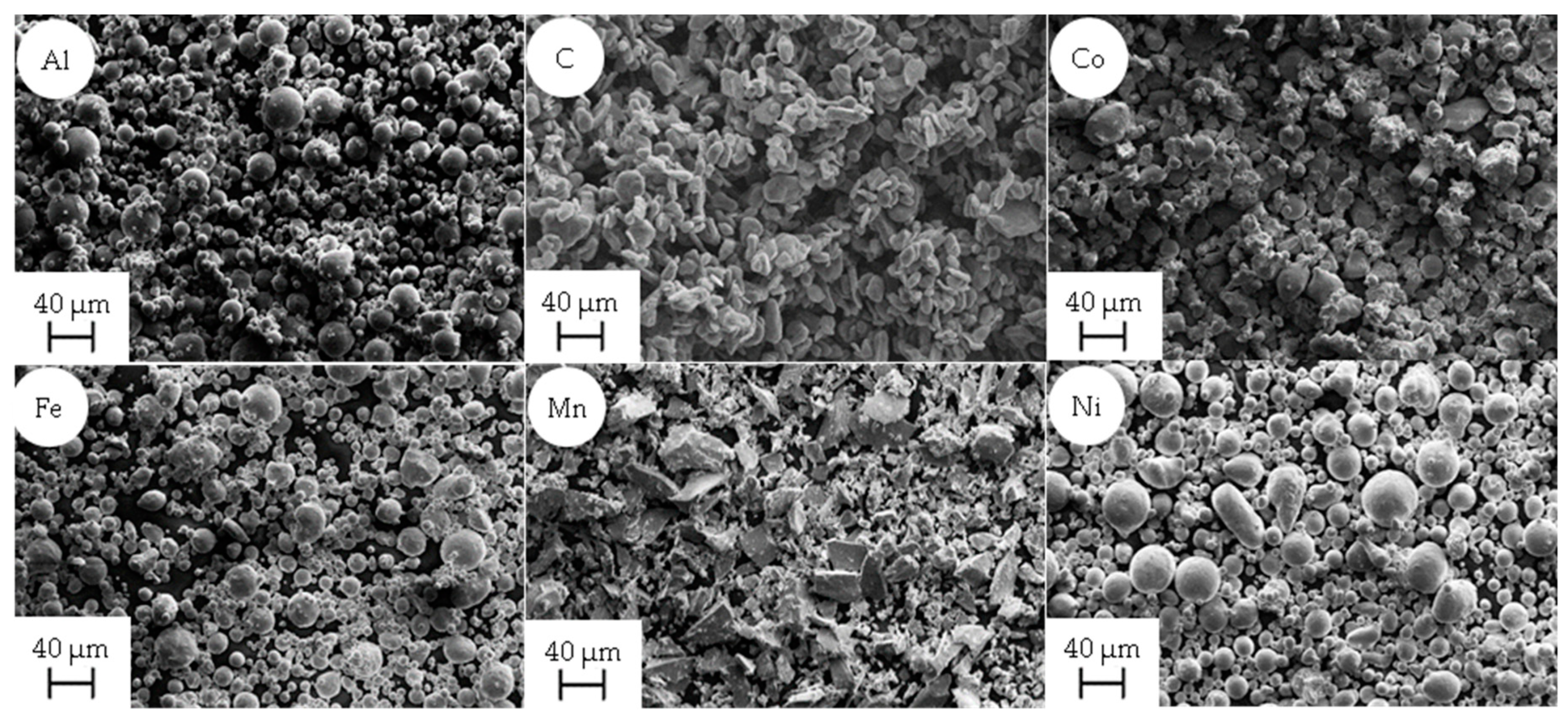
| Al | gas-atomized (Ar) | 10–45 | spherical | 58 ± 0.18 | 48 ± 0.33 | 1.31 ± 0.02 |
| C | ground | up to 45 | flake-shaped | 62 ± 0.18 | 90 ± 0.29 | 0.54 ± 0.02 |
| Co | water-atomized | 15–45 | splash-shaped | 48 ± 0.10 | 73 ± 0.06 | 3.40 ± 0.02 |
| Fe | gas-atomized (Ar) | 10–45 | spherical | 56 ± 0.18 | 74 ± 0.65 | 4.03 ± 0.03 |
| Mn | ground | up to 45 | flake-shaped | 52 ± 0.09 | 73 ± 0.09 | 2.50 ± 0.02 |
| Ni | gas-atomized (Ar) | 15–45 | spherical | 55 ± 0.19 | 65 ± 0.34 | 4.55 ± 0.02 |
| Alloy | Element | Al | C | Co | Fe | Mn | Ni |
|---|---|---|---|---|---|---|---|
| BASE | (at%) | 6.14 | – | 23.46 | 23.46 | 23.46 | 23.46 |
| (wt%) | 3.00 | – | 25.03 | 23.72 | 23.33 | 24.93 | |
| BASE + 0.6C | (at%) | 6.01 | 2.70 | 22.82 | 22.82 | 22.82 | 22.82 |
| (wt%) | 3.00 | 0.60 | 24.87 | 23.57 | 23.19 | 24.77 |
© 2019 by the authors. Licensee MDPI, Basel, Switzerland. This article is an open access article distributed under the terms and conditions of the Creative Commons Attribution (CC BY) license (http://creativecommons.org/licenses/by/4.0/).
Share and Cite
Ewald, S.; Kies, F.; Hermsen, S.; Voshage, M.; Haase, C.; Schleifenbaum, J.H. Rapid Alloy Development of Extremely High-Alloyed Metals Using Powder Blends in Laser Powder Bed Fusion. Materials 2019, 12, 1706. https://0-doi-org.brum.beds.ac.uk/10.3390/ma12101706
Ewald S, Kies F, Hermsen S, Voshage M, Haase C, Schleifenbaum JH. Rapid Alloy Development of Extremely High-Alloyed Metals Using Powder Blends in Laser Powder Bed Fusion. Materials. 2019; 12(10):1706. https://0-doi-org.brum.beds.ac.uk/10.3390/ma12101706
Chicago/Turabian StyleEwald, Simon, Fabian Kies, Steffen Hermsen, Maximilian Voshage, Christian Haase, and Johannes Henrich Schleifenbaum. 2019. "Rapid Alloy Development of Extremely High-Alloyed Metals Using Powder Blends in Laser Powder Bed Fusion" Materials 12, no. 10: 1706. https://0-doi-org.brum.beds.ac.uk/10.3390/ma12101706