Engineering Properties of Engineered Cementitious Composite and Multi-Response Optimization Using PCA-Based Taguchi Method


Abstract
:1. Introduction
2. Experimental Work
2.1. Materials
2.2. Mix Design
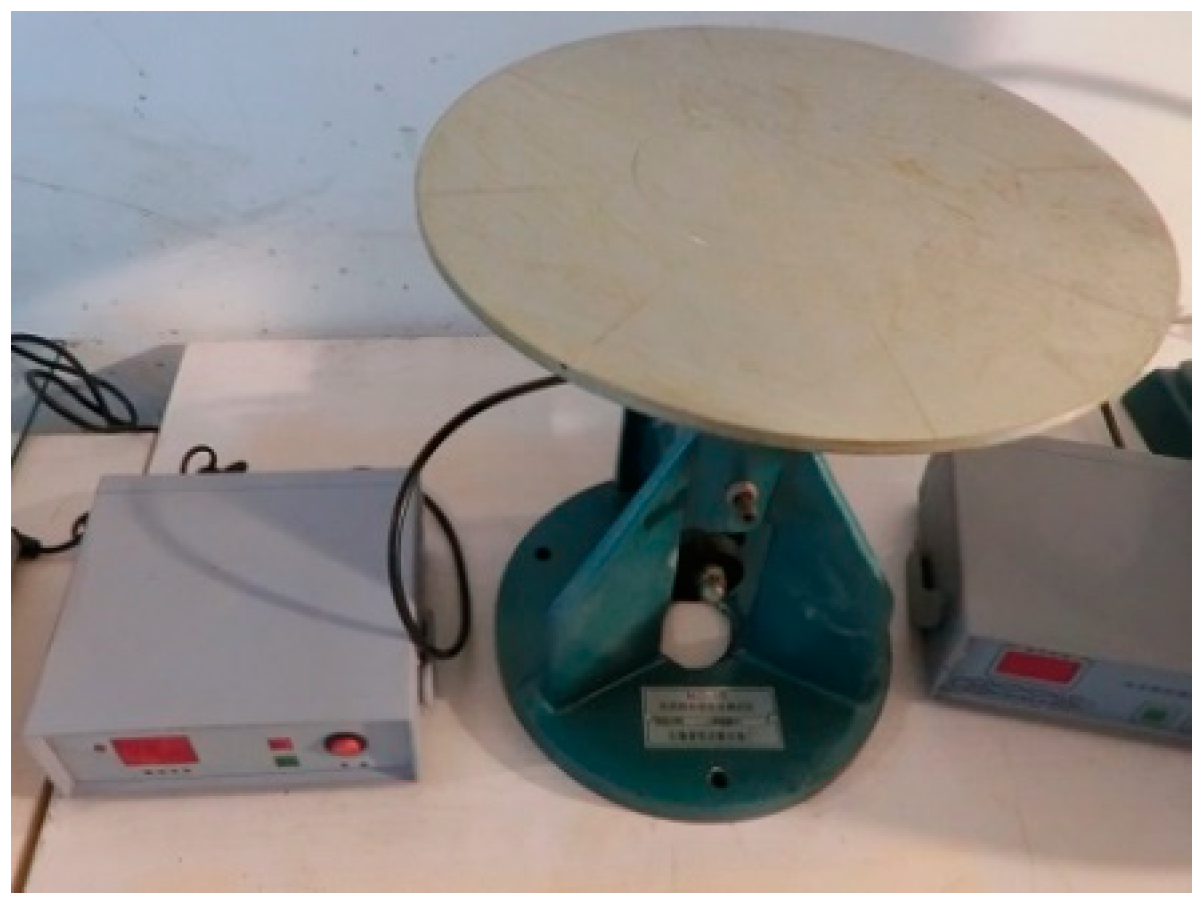
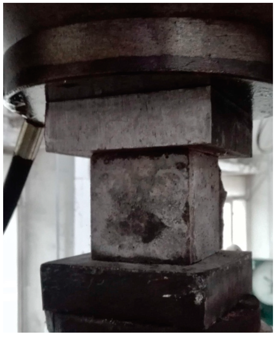
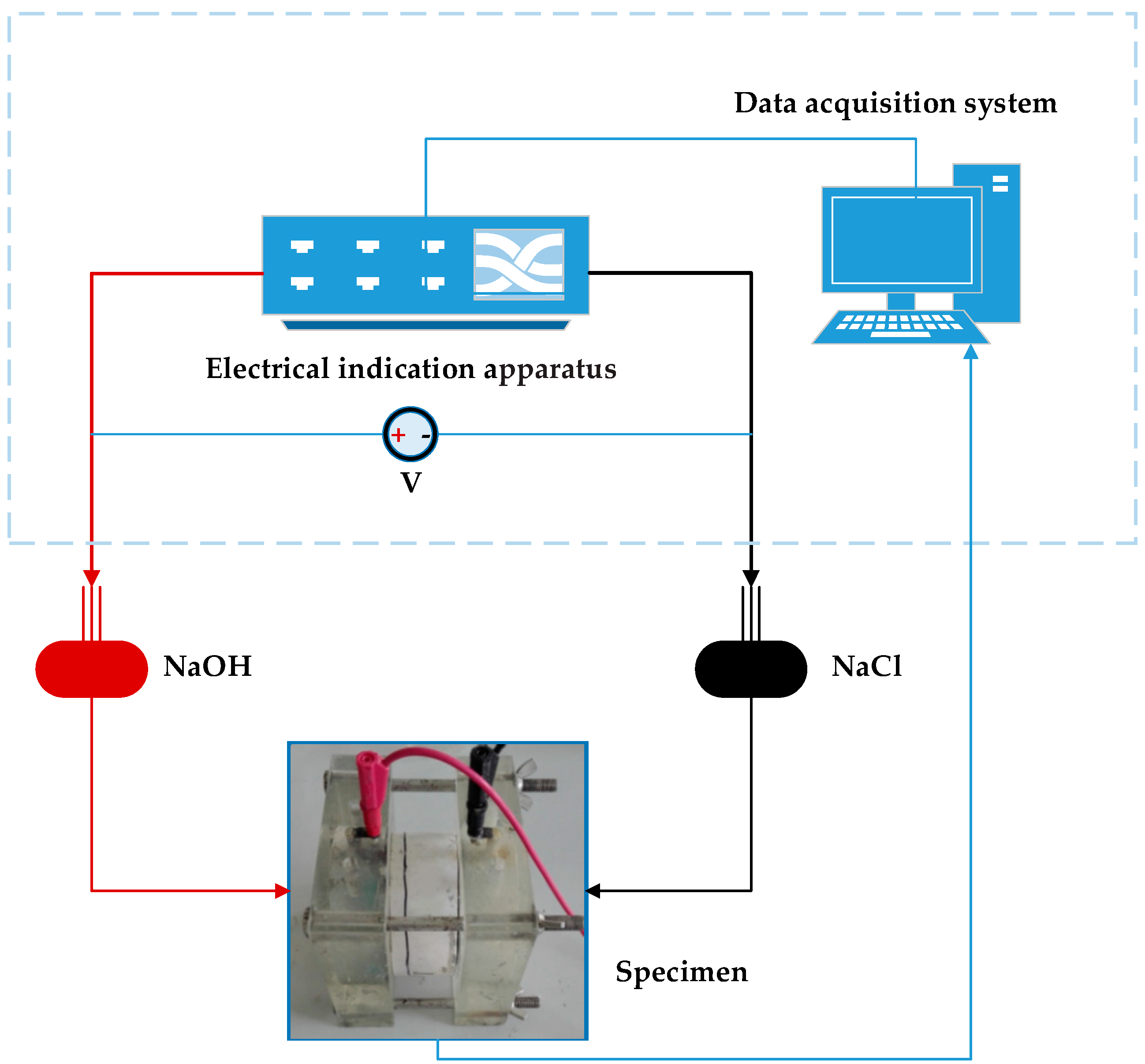
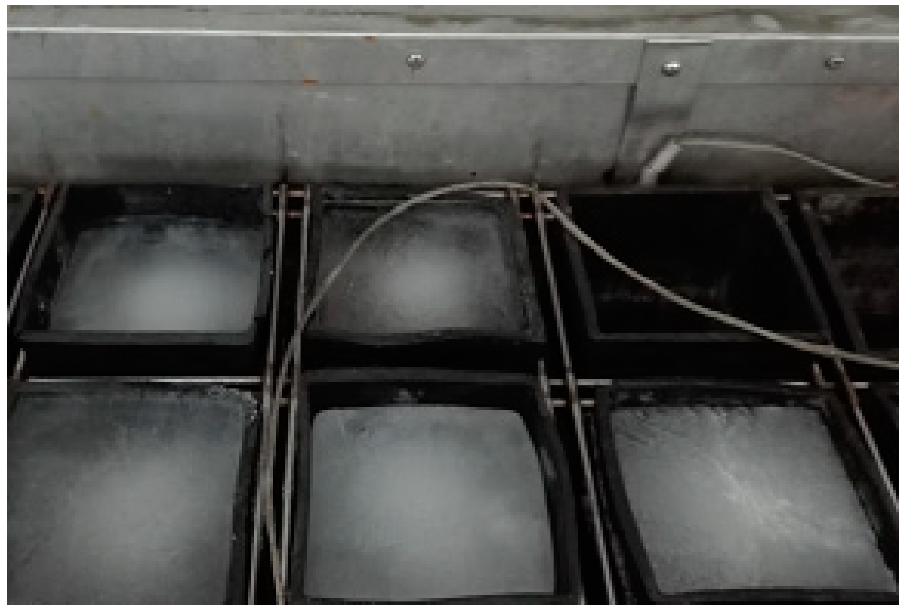
2.3. Test Method
3. Results and Discussion
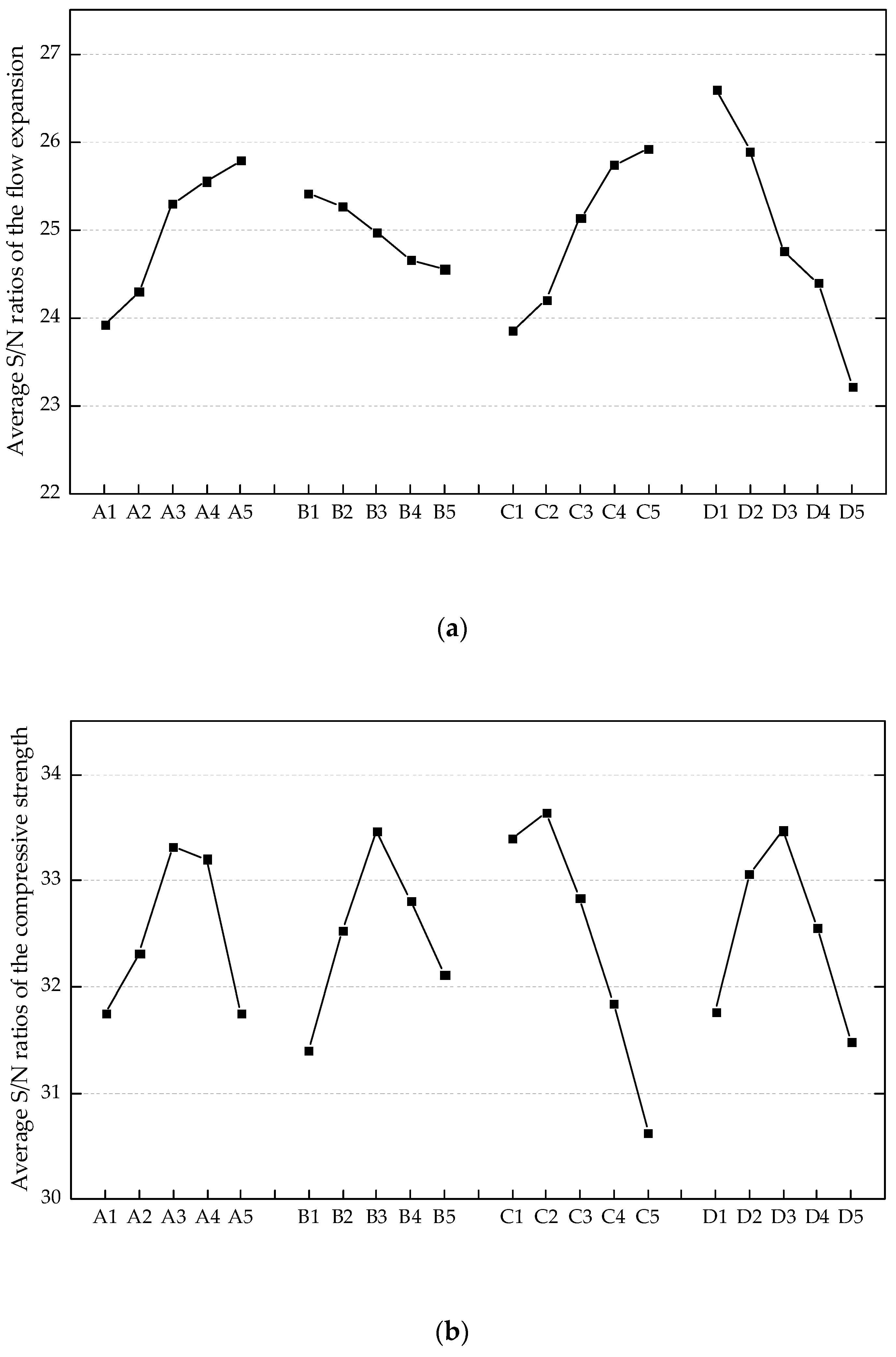
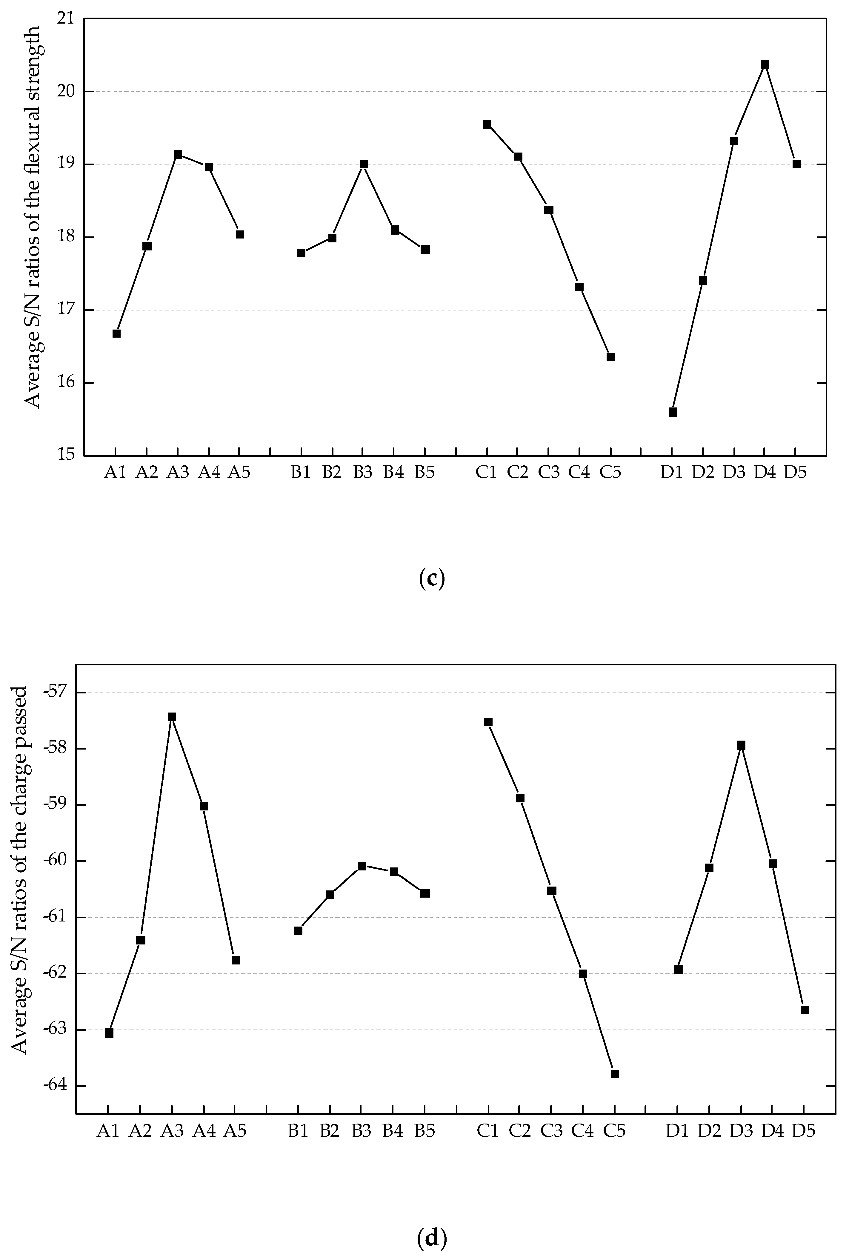
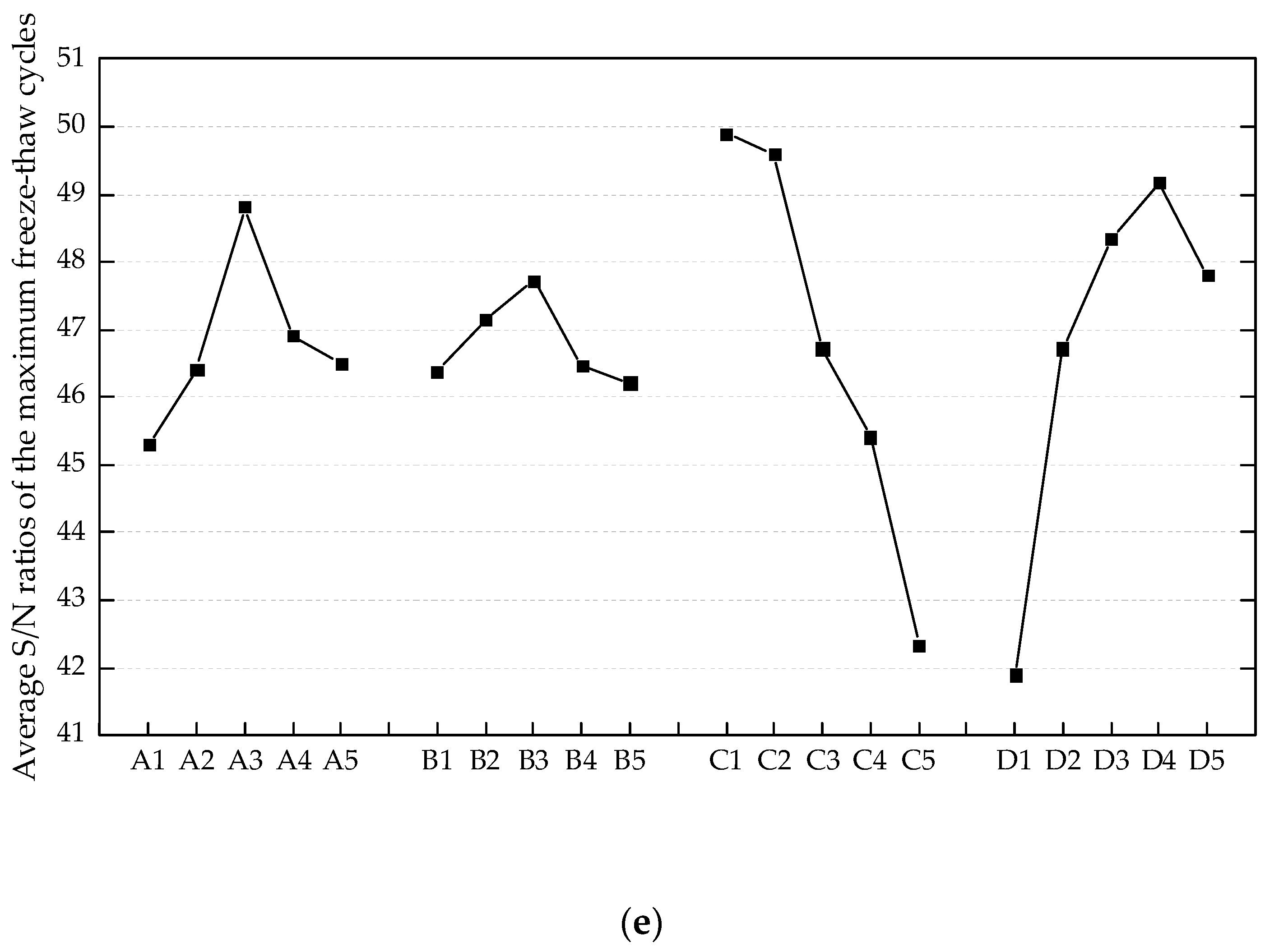
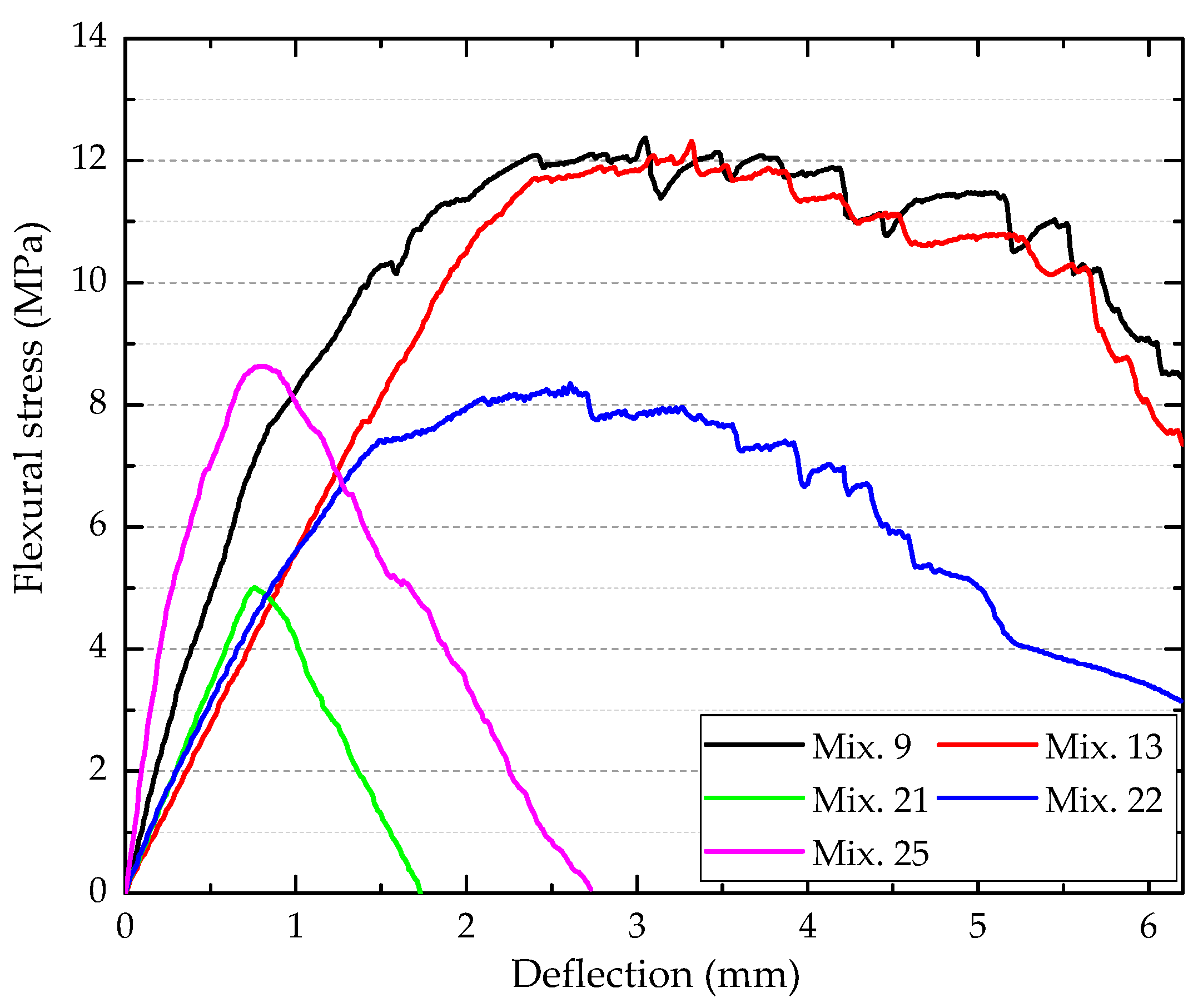
3.1. Engineering Properties of ECC
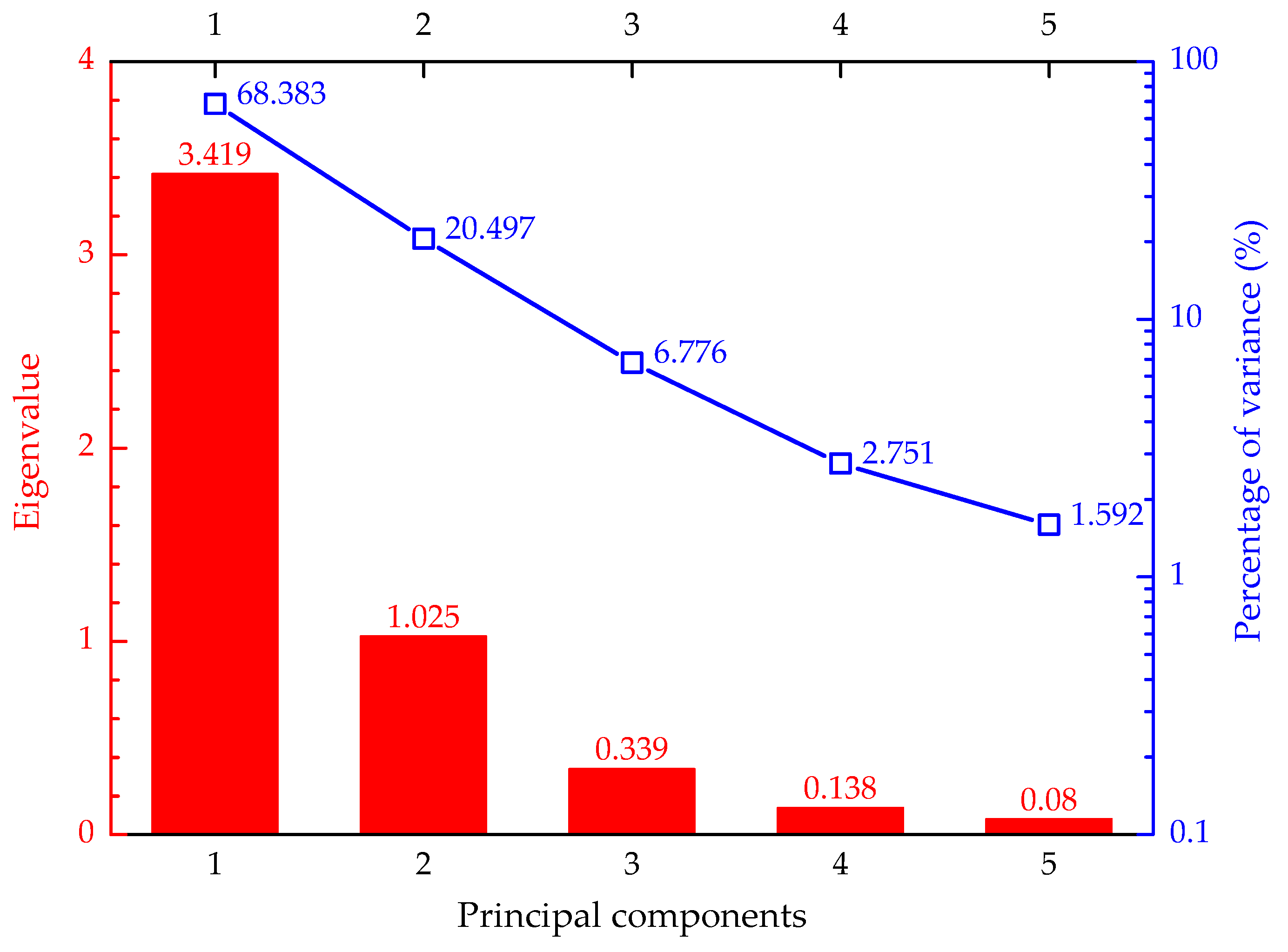
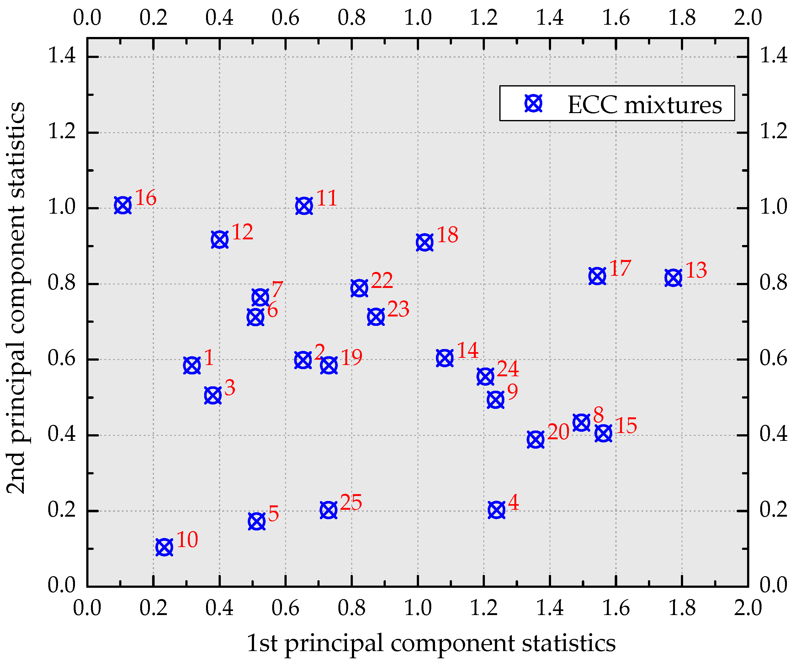
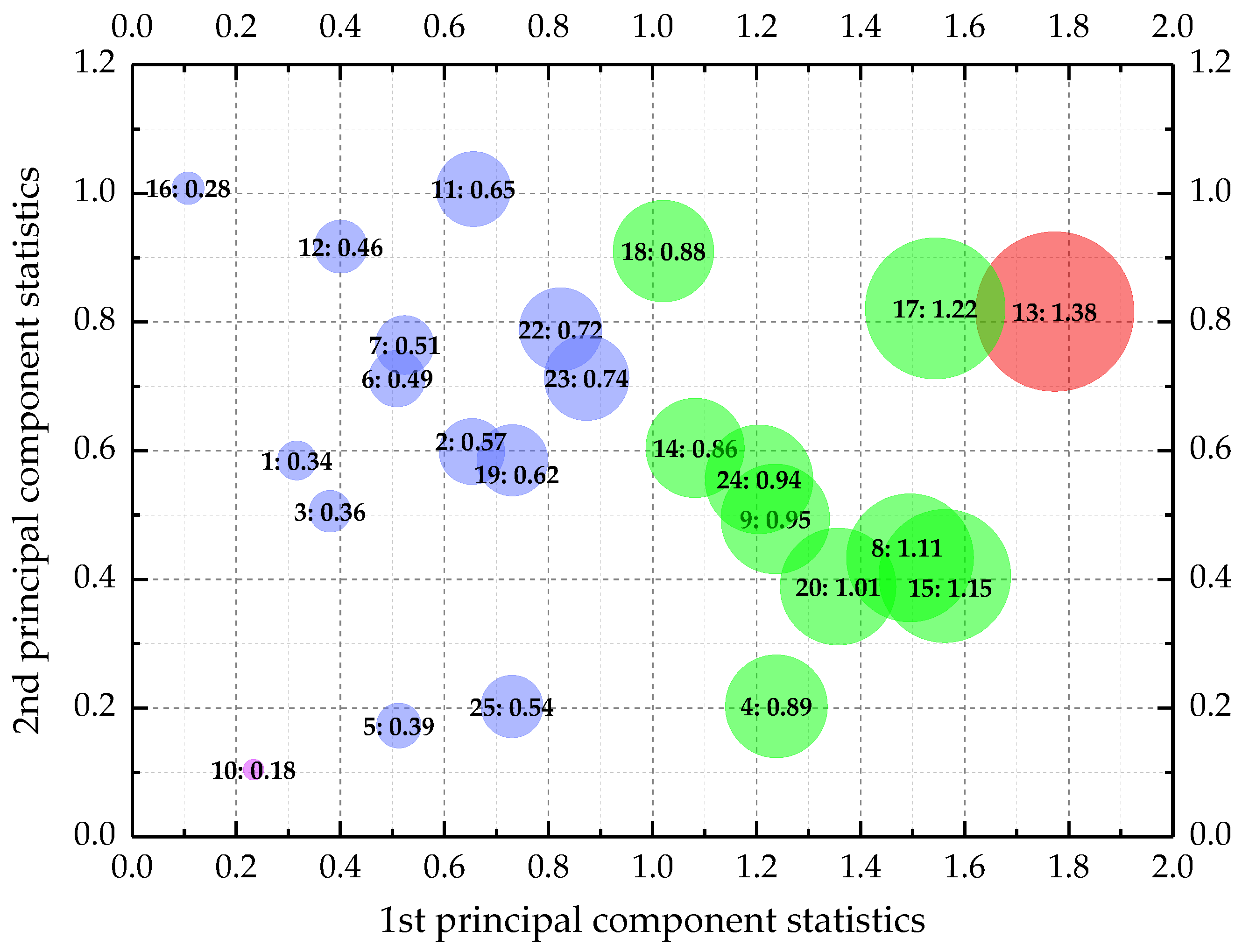
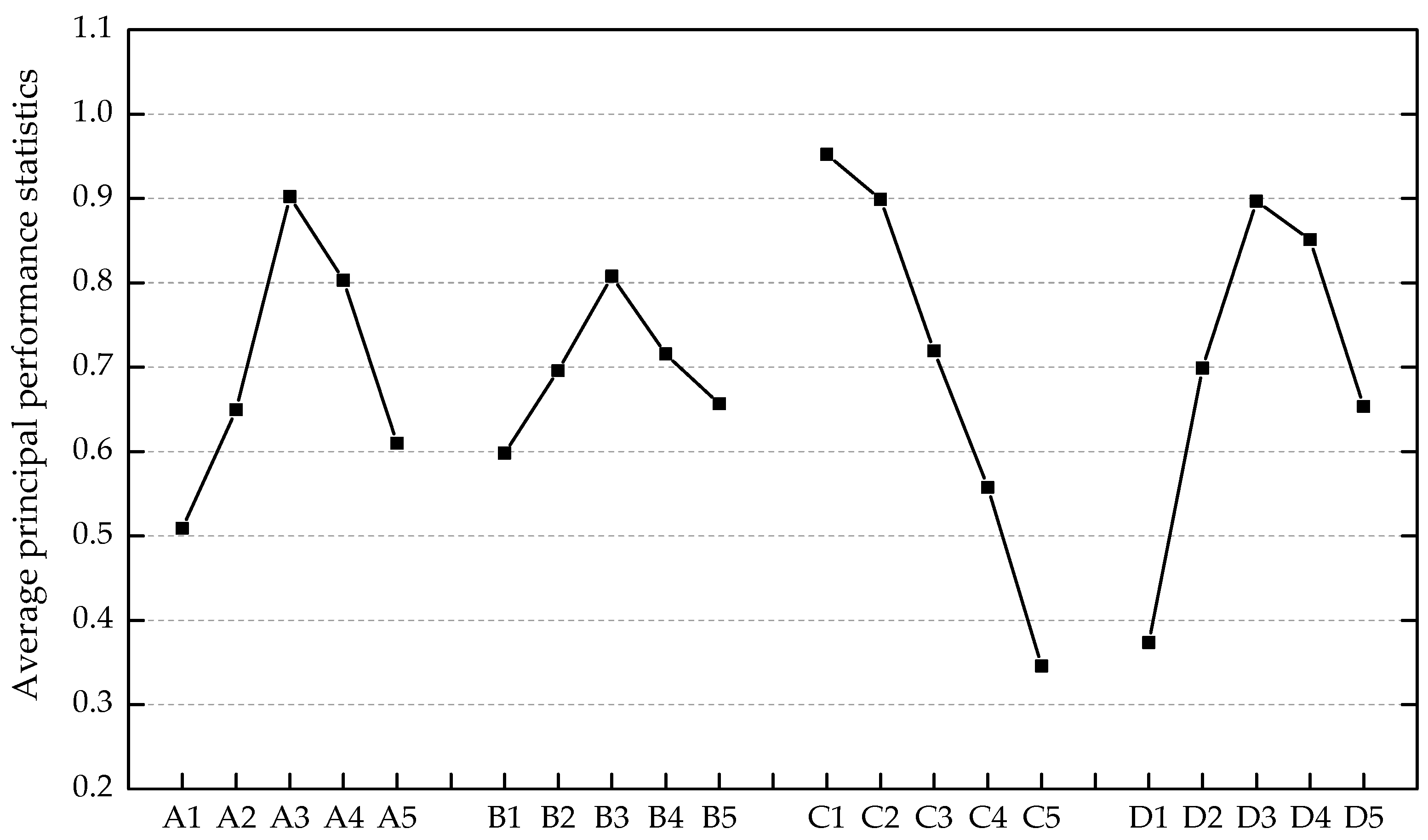
3.2. Principal Component Analysis of Test Data
3.3. Estimation of the Optimum Mix Formulation
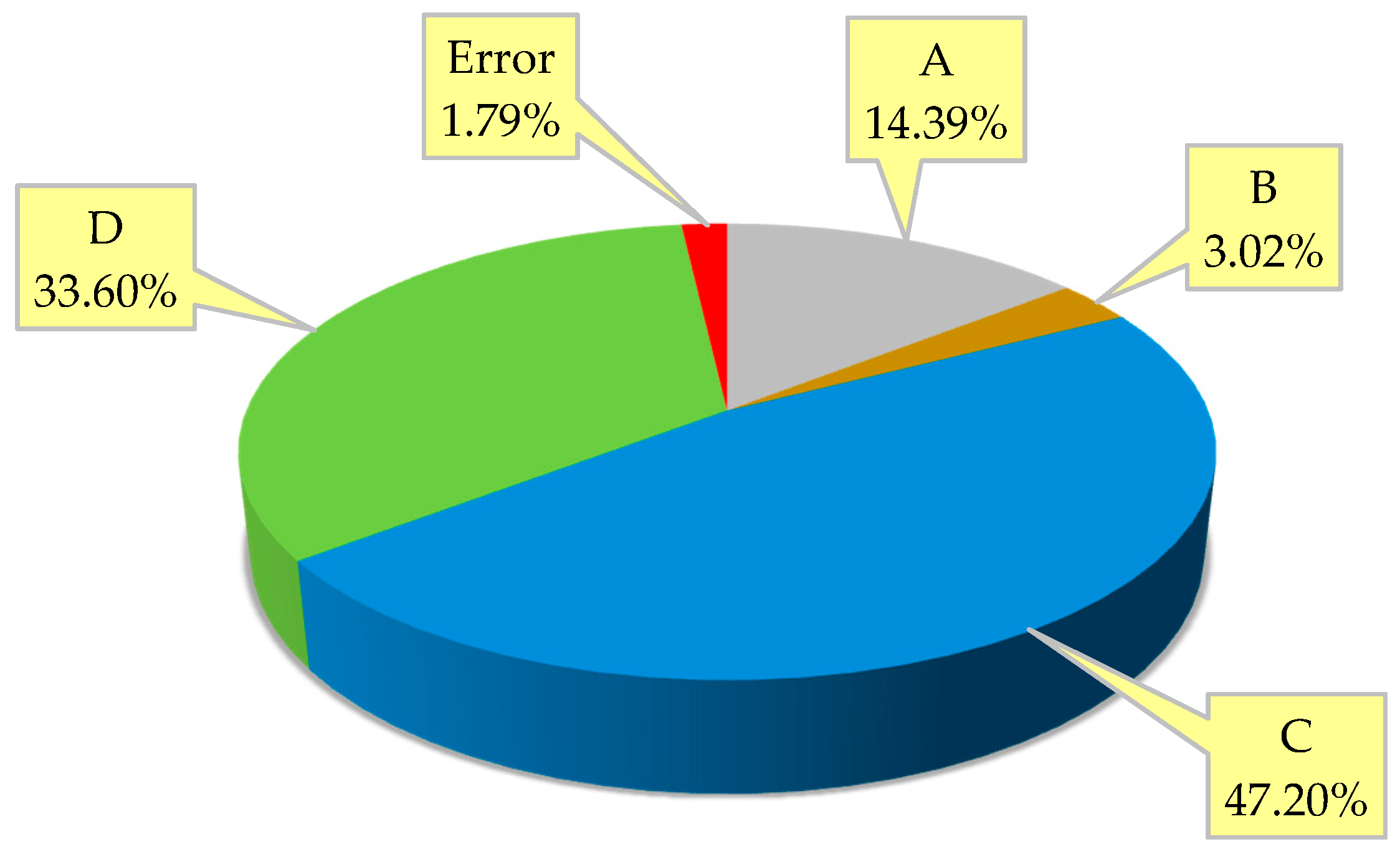
3.4. Analysis of Variance
3.5. Confirmation Experiment
4. Conclusions
- The original five engineering properties, including flow expansion, compressive strength, flexural strength, charge passed, and maximum freeze–thaw cycles, can be integrated into the single principal performance by the PCA without loss of important information. The principal performance embodies the essential integration of the original responses.
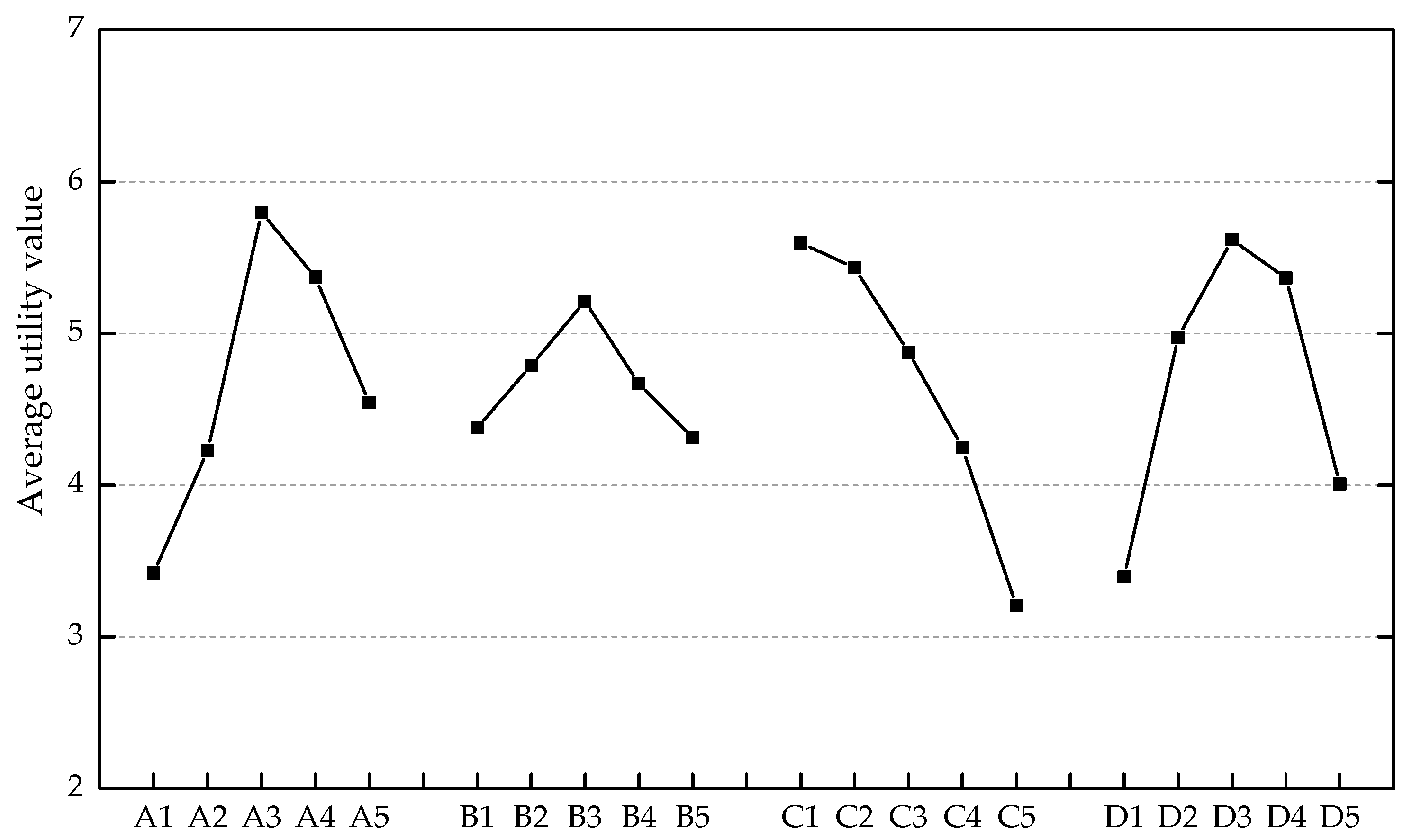
- A new approach based on the PCA was devised to help determine the weighting parameters for utility concept. The optimization results obtained from the updated utility concept were consistent with the PCA-based Taguchi method.
- The analyses of each engineering property and the principal performance indicated that PVA fibers and ground fly ash with proper content (VPVA: 0.010–0.015; FA: 0.350–0.525) can significantly improve the fresh, hardened, and durability properties of ECC materials. Moreover, the analysis of variance points to the considerable contribution of PVA fiber reinforcement (33.60%) to the principal performance.
- An optimum ECC mix formulation (FA: 0.350, S/B: 0.500, W/B: 0.2500, and VPVA: 0.010) is recommended through statistical analysis of the principal performance. This mix formulation provides the most desired balance of flowability, compressive strength, flexural strength, chloride ion penetration resistance, and freeze–thaw resistance, which was verified by the additional experiment. This hybrid method provides a reliable reference for the ECC’s multi-performance-oriented mix design.
Author Contributions
Funding
Acknowledgments
Conflicts of Interest
References
- Li, V.C.; Wang, S.X.; Wu, C. Tensile strain-hardening behavior of polyvinyl alcohol engineered cementitious composite (PVA-ECC). ACI Mater. J. 2001, 98, 483–492. [Google Scholar] [CrossRef]
- Lin, Z.; Li, V.C. Crack bridging in fiber reinforced cementitious composites with slip-hardening interfaces. J. Mech. Phys. Solids 1997, 45, 763–787. [Google Scholar] [CrossRef]
- Ahmed, S.F.U.; Maalej, M. Tensile strain hardening behaviour of hybrid steel-polyethylene fibre reinforced cementitious composites. Constr. Build. Mater. 2009, 23, 96–106. [Google Scholar] [CrossRef] [Green Version]
- Georgiou, A.V.; Pantazopoulou, S.J. Effect of fiber length and surface characteristics on the mechanical properties of cementitious composites. Constr. Build. Mater. 2016, 125, 1216–1228. [Google Scholar] [CrossRef]
- Maalej, M.; Li, V.C. Flexural/tensile strength ratio in engineered cementitious composites. J. Mater. Civ. Eng. 1994, 6, 513–528. [Google Scholar] [CrossRef]
- Zhou, J.; Qian, S.; Ye, G.; Copuroglu, O.; Breugel, K.V.; Li, V.C. Improved fiber distribution and mechanical properties of engineered cementitious composites by adjusting the mixing sequence. Cem. Concr. Compos. 2012, 34, 342–348. [Google Scholar] [CrossRef]
- Bouzoubaa, N.; Fournier, B.; Malhotra, V.M.; Golden, D.M. Mechanical properties and durability of concrete made with high-volume fly ash blended cement produced in cement plant. ACI Mater. J. 2002, 99, 560–567. [Google Scholar]
- American Coal Ash Association. Fly Ash Facts for Highway Engineers; Federal Highway Administration: Washington, DC, USA, 2003.
- Chindaprasirt, P.; Chai, J.; Sinsiri, T. Effect of fly ash fineness on compressive strength and pore size of blended cement paste. Cem. Concr. Compos. 2005, 27, 425–428. [Google Scholar] [CrossRef]
- Myadraboina, H.; Setunge, S.; Patnaikuni, I. Pozzolanic Index and lime requirement of low calcium fly ashes in high volume fly ash mortar. Constr. Build. Mater. 2017, 131, 690–695. [Google Scholar] [CrossRef]
- Chousidi, N.; Ioannou, I.; Rakanta, E.; Koutsodontis, C.; Batis, G. Effect of fly ash chemical composition on the reinforcement corrosion, thermal diffusion and strength of blended cement concretes. Constr. Build. Mater. 2016, 126, 86–97. [Google Scholar] [CrossRef]
- Chindaprasirt, P.; Homwuttiwong, S.; Sirivivatnanon, V. Influence of fly ash fineness on strength, drying shrinkage and sulfate resistance of blended cement mortar. Cem. Concr. Res. 2004, 34, 1087–1092. [Google Scholar] [CrossRef]
- Taguchi, G. Introduction to Quality Engineering; Asian Productivity Organization: Tokyo, Japan, 1990. [Google Scholar]
- Kackar, R.N. Off-line quality-control, parameter design, and the Taguchi method. J. Qual. Technol. 1985, 17, 176–188. [Google Scholar] [CrossRef]
- Maghsoodloo, S.; Ozdemir, G.; Jordan, V.; Huang, C.H. Strengths and limitations of Taguchi’s contributions to quality, manufacturing, and process engineering. J. Manuf. Syst. 2004, 23, 73–126. [Google Scholar] [CrossRef]
- Derringer, G.; Suich, R. Simultaneous optimization of several response variables. J. Qual. Technol. 1980, 12, 214–219. [Google Scholar] [CrossRef]
- Heidari, H.; Razmi, H. Multi-response optimization of magnetic solid phase extraction based on carbon coated Fe3O4 nanoparticles using desirability function approach for the determination of the organophosphorus pesticides in aquatic samples by HPLC-UV. Talanta 2012, 99, 13–21. [Google Scholar] [CrossRef] [PubMed]
- Jeyapaul, R.; Shahabudeen, P.; Krishnaiah, K. Simultaneous optimization of multi-response problems in the Taguchi method using genetic algorithm. Int. J. Adv. Manuf. Technol. 2006, 30, 870–878. [Google Scholar] [CrossRef]
- Pasandideh, S.H.R.; Niaki, S.T.A. Multi-response simulation optimization using genetic algorithm within desirability function framework. Appl. Math. Comput. 2006, 175, 366–382. [Google Scholar] [CrossRef]
- Asilturk, I.; Neseli, S. Multi response optimisation of CNC turning parameters via Taguchi method-based response surface analysis. Measurement 2012, 45, 785–794. [Google Scholar] [CrossRef]
- Kumar, A.; Kumar, V.; Kumar, J. Multi-response optimization of process parameters based on response surface methodology for pure titanium using WEDM process. Int. J. Adv. Manuf. Technol. 2013, 68, 2645–2668. [Google Scholar] [CrossRef]
- Singh, H.; Kumar, P. Optimizing multi-machining characteristics through Taguchi’s approach and utility concept. J. Manuf. Technol. Manag. 2006, 17, 255–274. [Google Scholar] [CrossRef]
- Walia, R.S.; Shan, H.S.; Kumar, P. Multi-response optimization of CFAAFM process through Taguchi method and utility concept. Mater. Manuf. Process. 2006, 21, 907–914. [Google Scholar] [CrossRef]
- Datta, S.; Nandi, G.; Bandyopadhyay, A.; Pal, P.K. Application of PCA-based hybrid Taguchi method for correlated multicriteria optimization of submerged arc weld: A case study. Int. J. Adv. Manuf. Technol. 2009, 45, 276–286. [Google Scholar] [CrossRef]
- Sadowski, L.; Nikoo, M.; Nikoo, M. Principal Component Analysis combined with a Self Organization Feature Map to determine the pull-off adhesion between concrete layers. Constr. Build. Mater. 2015, 78, 386–396. [Google Scholar] [CrossRef]
- Kaiser, H.F. The application of electronic computers to factor analysis. Educ. Psychol. Meas. 1960, 20, 141–151. [Google Scholar] [CrossRef]
- Antony, J. Multi-response optimization in industrial experiments using Taguchi’s quality loss function and principal component analysis. Qual. Reliab. Eng. Int. 2000, 16, 3–8. [Google Scholar] [CrossRef]
- Fung, C.P.; Kang, P.C. Multi-response optimization in friction properties of PBT composites using Taguchi method and principle component analysis. J. Mater. Process. Technol. 2005, 170, 602–610. [Google Scholar] [CrossRef]
- Ray, J.A. Optimization of process parameters of green electrical discharge machining using principal component analysis (PCA). Int. J. Adv. Manuf. Technol. 2016, 87, 1299–1311. [Google Scholar] [CrossRef]
- Nguyen, H.A.D.; Shin, N.K.; Lee, C. Multi-response optimization of R2R gravure printing using orthogonal array and principal component analysis as a weighting factor. Int. J. Adv. Manuf. Technol. 2017, 90, 3595–3606. [Google Scholar] [CrossRef]
- ASTM International. ASTM C230: Standard Specification for Flow Table for Use in Tests of Hydraulic Cement; ASTM International: West Conshohocken, PA, USA, 2008. [Google Scholar]
- MOHURD. GB/T 50081-2002, Standard for Test Method of Mechanical Properties on Ordinary Concrete; Architecture & Building Press: Beijing, China, 2003. (In Chinese)
- ASTM International. ASTM C1202-17a: Standard Test Method for Electrical Indication of Concrete’s Ability to Resist Chloride ion Penetration; ASTM International: West Conshohocken, PA, USA, 2017. [Google Scholar]
- MOHURD. GB/T 50082-2009, Standard for Test Methods of Long-Term Performance and Durability of Ordinary Concrete; China Architecture & Building Press: Beijing, China, 2009. (In Chinese)
- ASTM International. ASTM C666: Standard Test Method for Resistance of Concrete to Rapid Freezing and Thawing; ASTM International: West Conshohocken, PA, USA, 2015. [Google Scholar]
- Laskar, A.I.; Talukdar, S. Rheological behavior of high performance concrete with mineral admixtures and their blending. Constr. Build. Mater. 2008, 22, 2345–2354. [Google Scholar] [CrossRef]
- Lee, S.H.; Kim, H.J.; Sakai, E.; Daimon, M. Effect of particle size distribution of fly ash–cement system on the fluidity of cement pastes. Cem. Concr. Res. 2003, 33, 763–768. [Google Scholar] [CrossRef]
- Nanthagopalan, P.; Haist, M.; Santhanam, M.; Harald, S.M. Investigation on the influence of granular packing on the flow properties of cementitious suspensions. Cem. Concr. Compos. 2008, 30, 763–768. [Google Scholar] [CrossRef]
- Kwan, A.K.H.; Chen, J.J. Adding fly ash microsphere to improve packing density, flowability and strength of cement paste. Powder Technol. 2013, 234, 19–25. [Google Scholar] [CrossRef]
- Şahmaran, M.; ÖZbay, E.; Hasan, E.Y.; Lachemi, M.; Li, V.C. Frost resistance and microstructure of engineered cementitious composites: Influence of fly ash and micro poly-vinyl-alcohol fiber. Cem. Concr. Compos. 2012, 34, 156–165. [Google Scholar] [CrossRef]
- Liu, J.C.; Tan, K.H.; Zhang, D. Multi-response optimization of post-fire performance of strain hardening cementitious composite. Cem. Concr. Compos. 2017, 80, 80–90. [Google Scholar] [CrossRef]
- Rahim, A.; Sharma, U.K.; Murugesan, K.; Sharma, A.; Arora, P. Multi-response optimization of post fire residual compressive strength of high performance concrete. Constr. Build. Mater. 2013, 38, 265–273. [Google Scholar] [CrossRef]
- Zoalfakar, S.H.; Elsissy, M.A.; Shaheen, Y.B.; Hamada, A.A. Multiresponse optimization of postfire residual properties of fiber-reinforced high-performance concrete. J. Mater. Civ. Eng. 2016, 28, 04016111. [Google Scholar] [CrossRef]
- Bunn, D.W. Analysis for Optimal Decisions; John Wiley and Sons Ltd.: London, UK, 1982; ISBN 978-047-110-132-1. [Google Scholar]
- Mandal, N.; Doloi, B.; Mondal, B.; Das, R. Optimization of flank wear using Zirconia Toughened Alumina (ZTA) cutting tool: Taguchi method and Regression analysis. Measurement 2011, 44, 2149–2155. [Google Scholar] [CrossRef]


| Hydraulic Binders | Chemical Analysis of Basic Oxides (wt. %) | |||||
|---|---|---|---|---|---|---|
| SiO2 | Al2O3 | Fe2O3 | CaO | MgO | SO3 | |
| Portland cement | 21.08 | 5.47 | 3.96 | 62.28 | 1.73 | 2.63 |
| Ground fly ash | 55.70 | 25.63 | 5.65 | 6.93 | 2.25 | 0.60 |
| Mixture | Labels | Factors & Levels | Superplasticizer (%) | |||
|---|---|---|---|---|---|---|
| A(FA) | B(S/B) | C(W/B) | D(VPVA) | |||
| 1 | A1B1C1D1 | 0 | 0.250 | 0.2500 | 0 | 0.82 |
| 2 | A1B4C3D2 | 0 | 0.625 | 0.3750 | 0.005 | 0.38 |
| 3 | A1B2C5D3 | 0 | 0.375 | 0.5000 | 0.010 | 0.09 |
| 4 | A1B5C2D4 | 0 | 0.750 | 0.3125 | 0.015 | 1.07 |
| 5 | A1B3C4D5 | 0 | 0.500 | 0.4375 | 0.020 | 0.94 |
| 6 | A2B4C2D1 | 0.175 | 0.625 | 0.3125 | 0 | 0.22 |
| 7 | A2B2C4D2 | 0.175 | 0.375 | 0.4375 | 0.005 | 0.05 |
| 8 | A2B5C1D3 | 0.175 | 0.750 | 0.2500 | 0.010 | 1.51 |
| 9 | A2B3C3D4 | 0.175 | 0.500 | 0.3750 | 0.015 | 0.30 |
| 10 | A2B1C5D5 | 0.175 | 0.250 | 0.5000 | 0.020 | 0.50 |
| 11 | A3B2C3D1 | 0.350 | 0.375 | 0.3750 | 0 | 0.63 |
| 12 | A3B5C5D2 | 0.350 | 0.750 | 0.5000 | 0.005 | 0.06 |
| 13 | A3B3C2D3 | 0.350 | 0.500 | 0.3125 | 0.010 | 0.48 |
| 14 | A3B1C4D4 | 0.350 | 0.250 | 0.4375 | 0.015 | 0 |
| 15 | A3B4C1D5 | 0.350 | 0.625 | 0.2500 | 0.020 | 1.52 |
| 16 | A4B5C4D1 | 0.525 | 0.750 | 0.4375 | 0 | 0.48 |
| 17 | A4B3C1D2 | 0.525 | 0.500 | 0.2500 | 0.005 | 0.68 |
| 18 | A4B1C3D3 | 0.525 | 0.250 | 0.3750 | 0.010 | 0.10 |
| 19 | A4B4C5D4 | 0.525 | 0.625 | 0.5000 | 0.015 | 0.05 |
| 20 | A4B2C2D5 | 0.525 | 0.375 | 0.3125 | 0.020 | 0.59 |
| 21 | A5B3C5D1 | 0.700 | 0.500 | 0.5000 | 0 | 0 |
| 22 | A5B1C2D2 | 0.700 | 0.250 | 0.3125 | 0.005 | 0.67 |
| 23 | A5B4C4D3 | 0.700 | 0.625 | 0.4375 | 0.010 | 0.04 |
| 24 | A5B2C1D4 | 0.700 | 0.375 | 0.2500 | 0.015 | 1.42 |
| 25 | A5B5C3D5 | 0.700 | 0.750 | 0.3750 | 0.020 | 0.87 |
| Response | Weighting Parameter |
|---|---|
| Flow expansion | 0.203 |
| Compressive strength | 0.192 |
| Flexural strength | 0.191 |
| Charge passed | 0.207 |
| Maximum freeze–thaw cycles | 0.207 |
| Mix Design Factor | DF | SS | MS | F-Value | Contribution (%) | Significance |
|---|---|---|---|---|---|---|
| A | 4 | 105.75 | 26.44 | 16.05 | 14.39 | O |
| B | 4 | 22.19 | 5.55 | 3.37 | 3.02 | X |
| C | 4 | 346.93 | 86.73 | 52.64 | 47.20 | O |
| D | 4 | 246.92 | 61.73 | 37.47 | 33.60 | O |
| Error | 8 | 13.18 | 1.65 | - | 1.79 | - |
| Total | 24 | 734.97 | - | - | 100.00 | - |
| Optimum Combination (A3B3C1D3) | Estimated Value | Experimental Value |
|---|---|---|
| Flow expansion (cm) | 15.84 ± 3.64 | 17.00 |
| Compressive strength (MPa) | 63.16 ± 8.51 | 60.50 |
| Flexural strength (MPa) | 13.00 ± 1.83 | 12.17 |
| Charge passed (C) | 219.43 ± 281.43 | 359.77 |
| Maximum freeze–thaw cycles | 414 ± 73.99 | 425 |
© 2019 by the authors. Licensee MDPI, Basel, Switzerland. This article is an open access article distributed under the terms and conditions of the Creative Commons Attribution (CC BY) license (http://creativecommons.org/licenses/by/4.0/).
Share and Cite
Zhong, J.; Shi, J.; Shen, J.; Zhou, G.; Wang, Z. Engineering Properties of Engineered Cementitious Composite and Multi-Response Optimization Using PCA-Based Taguchi Method. Materials 2019, 12, 2402. https://0-doi-org.brum.beds.ac.uk/10.3390/ma12152402
Zhong J, Shi J, Shen J, Zhou G, Wang Z. Engineering Properties of Engineered Cementitious Composite and Multi-Response Optimization Using PCA-Based Taguchi Method. Materials. 2019; 12(15):2402. https://0-doi-org.brum.beds.ac.uk/10.3390/ma12152402
Chicago/Turabian StyleZhong, Junfei, Jun Shi, Jiyang Shen, Guangchun Zhou, and Zonglin Wang. 2019. "Engineering Properties of Engineered Cementitious Composite and Multi-Response Optimization Using PCA-Based Taguchi Method" Materials 12, no. 15: 2402. https://0-doi-org.brum.beds.ac.uk/10.3390/ma12152402