Cost Analysis of Prefabricated Elements of the Ordinary and Lightweight Concrete Walls in Residential Construction


Faculty of Civil and Environmental Engineering, Gdańsk University of Technology, Narutowicza 11/12 Str., 80-233 Gdańsk, Poland
*
Author to whom correspondence should be addressed.
Materials 2019, 12(21), 3629; https://0-doi-org.brum.beds.ac.uk/10.3390/ma12213629
Submission received: 30 September 2019
/
Revised: 28 October 2019
/
Accepted: 31 October 2019
/
Published: 4 November 2019
(This article belongs to the Special Issue Mechanical, Thermal, and Hygric Properties of Lightweight Composites for Construction Use)
Abstract
:Global economic growth causes an increase in natural resources exploitation, particularly in construction branch. The growing use of electricity contributes to climate change. Therefore, it is necessary to search the solutions, which will allow for reducing natural resources exploitation. One of the many opportunities to do that is the application of the recycled materials. The authors of the given article have analyzed three variants of construction solutions. One of them was the production of the walls of a building from reinforced concrete prefabricates with styrofoam insulation layer. The second variant for analysis were prefabricated walls from lightweight concrete, made of sintered clay aggregate with a foam core. The third proposed variant was a system of multi-layered walls, which was made of lightweight concrete with granulated expanded glass aggregate (GEGA). The main objective of the research was to assess the use of lightweight GEGA prefabricates, focusing on economic and technological aspects of the solution. The authors have analyzed the entire construction costs; ceilings and stairs were assumed as reinforced concrete elements. In calculations, the weight of the elements was taken into account, as well as transportation and mounting costs. On the basis of this cost analysis, it was concluded that the use of prefabricated element, made of lightweight concrete with GEGA, could be a replacement for the solutions, widely applied until these days. The analysis has also shown that the use of prefabricates with GEGA is sensible from the economic viewpoint, as it allows for saving construction time. Moreover, the solutions, proposed here, allow for saving natural resources and assuming a more environmentally friendly and caring attitude.
1. Introduction
Science and technology development enable the implementation of innovative solutions in construction and architecture. Multiple changes in concrete production and prefabrication are being introduced. At present, concrete as a modern composite is regarded not only as a construction material, but also as an insulation material or aesthetic architectural finish. Concrete properties depend on concrete mixture components.
Concrete technologists face increasing expectations, as more and more modifications of both ready-mix and prefabricates become possible to be made, maintaining material’s durability and strength at the same time. It is also possible to modify cement binder by means of applying admixtures and additives or natural, artificial, or recycled aggregates alongside with sustainable development principles while obtaining components, producing ready-mix and prefabricating elements.
New technologies in artificial lightweight aggregate production enable meeting complex requirements of the construction contractors as for strength, insulation, acoustic, fire-resistance, and aesthetic properties. According to [1], lightweight concrete is a concrete with not less than 800 kg/m3 and not more than 2000 kg/m3 volume density in a dry state and with strength from LC 8/9 to LC 80/88. High strength lightweight concrete is a concrete with compression strength that is higher than LC50/55. Currently, due to the possibility of the use of the additives and chemical admixtures, it is possible to obtain considerably higher strength parameters for lightweight concrete than is required by the standard. Lightweight concrete and its modifications are subject to a great number of research at the moment [2,3,4,5,6,7]. Due to the possibility of application of the prefabricated elements, made of lightweight concrete as construction elements, it is necessary to design them with a great deal of precision and take into account the requirements that specifically apply to the type of construction. The components of a mix should be selected with the thought of safety of the future users of the construction and, also, the durability of the elements and their physical and mechanical properties. Basic features of lightweight concrete, which make a difference, are lower volume density and better insulation properties [8,9,10,11]. Lightweight concrete with its volume density of about 1800 kg/m3 shows thermal insulation properties that are similar to those of ceramic brick wall [12,13]. The use of lightweight concrete in prefabricates results in the building’s specific weight reduction and thermal and acoustic insulation increase of a building [14,15,16]. The application of a lightweight aggregate, e.g., foam glass aggregate, allows for a significant decrease in concrete volume density and thermal insulation coefficient reduction [17,18,19,20,21].
2. Materials and Methods
Prefabricated Concrete and Residential Buildings
Prefabrication gives great opportunities for public, residential, and industrial construction. The essence of this technology lies in the optimization of construction process, safety procedures improvement, limitation of the waste production, and minimization of exhaust gas emission. Moreover, the search of the effective methods of construction project realization in keeping with the aesthetic and comfort values of the constructed object is of high importance. The aim of prefabrications is saving construction time, reduction of the number of construction processes, minimization of construction’s cross section, and quality improvement [22,23,24,25]. Prefabricated elements are widely used in residential construction as multi-layered walls, ceilings, and balcony panels due to their numerous advantages. The prefabricate production process led, in modern conditions, strictly following technological procedures, going on non-dependent on atmospheric conditions production floors, allows for receiving perfect quality products. However, it is crucial to bear in mind the necessity of strict overall investment control and preliminary assessment of the difficulties while mounting. Economic analysis of the investment is also obligatory, so as to make sure of the financial reasonability of the project [26].
Table 1 presents a comparison of the building erection system by means of the method of performing all activities at the construction site and using prefabricated elements.
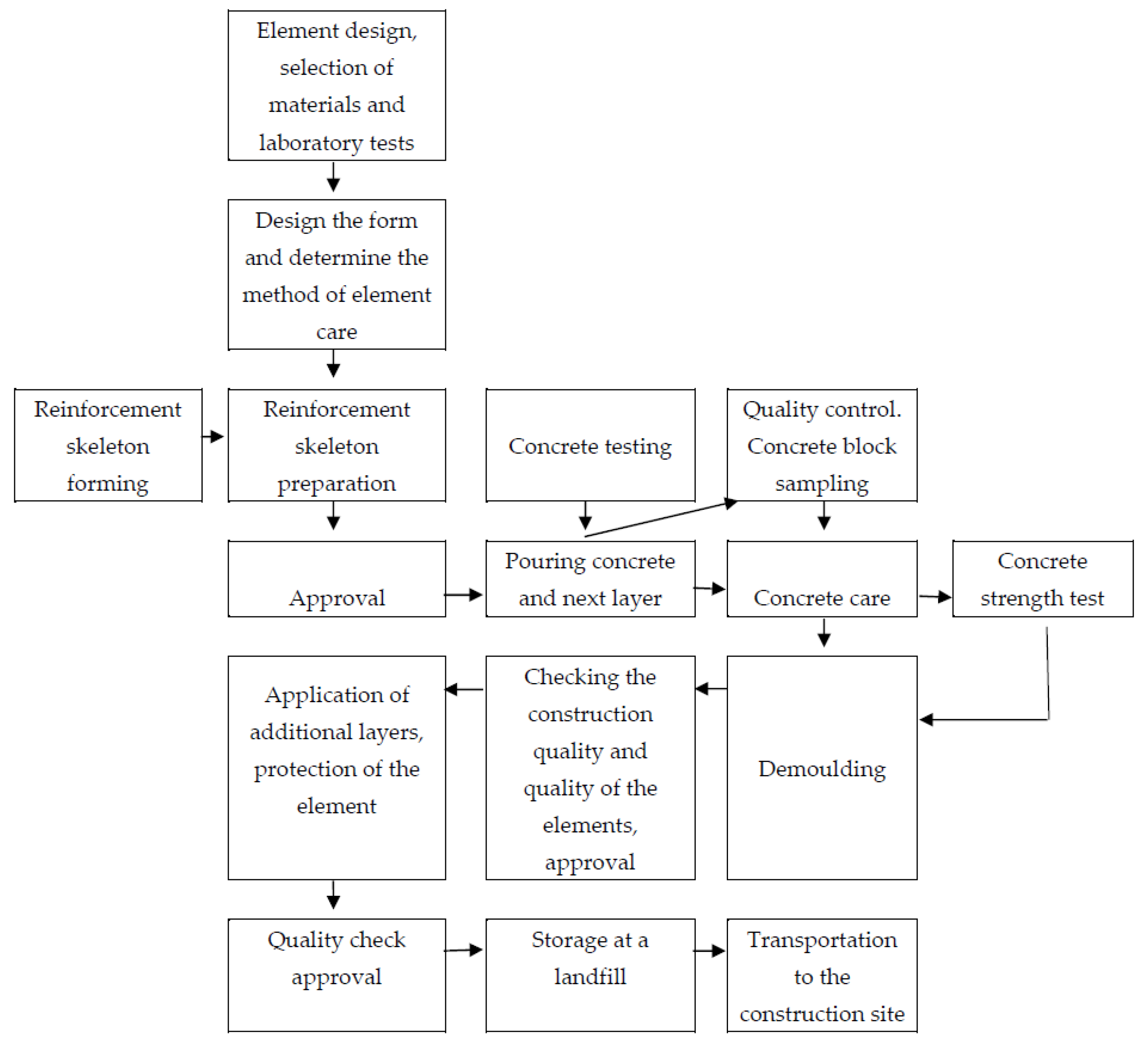
The prefabricated multi-layer wall is frequently used in the prefabricated integrated residential buildings, which are characterized by easy installation and short construction time [27,28,29]. Figure 1 shows the process of manufacturing a prefabricated wall element.
Further analyzing the case of installing prefabricated walls in an apartment building, thermal conductivity aspects were considered. Heat transfer coefficient for the walls was determined, while taking into account higher requirements, connected with thermal insulation in the countries with occurring problem of significant indoor and outdoor temperature difference. Table 2 shows the requirements for meeting for thermal conductivity of outer and inner walls of the residential building.
According to the regulations, connected with thermal insulation of the buildings, the maximum total heat transfer coefficient of the walls between the corridors and apartments constitutes U = 1.0 W/(m2·K). In the case of outer walls, depending of the assumed temperature for calculations, the coefficient U = 0.3 W/(m2·K) or U = 0.8 W/(m2·K). These requirements cannot be met by one-layer reinforced-concrete wall or brick wall. One could apply a thermal insulation layer of foam panels or mineral wool or use thermal insulation plaster in order to meet the latter thermal insulation requirements. However, these solutions will generate additional costs and will make the walls thicker. Additional construction works, connected with thermal insulation, will cause construction deadlines prolongation. Therefore, an alternative solution lies in using multilayer prefabricated elements, which are made of lightweight concrete.
Table 3 presents the values for calculation of the physical properties of the selected materials, determined according to [31] and this article’s authors’ own research.
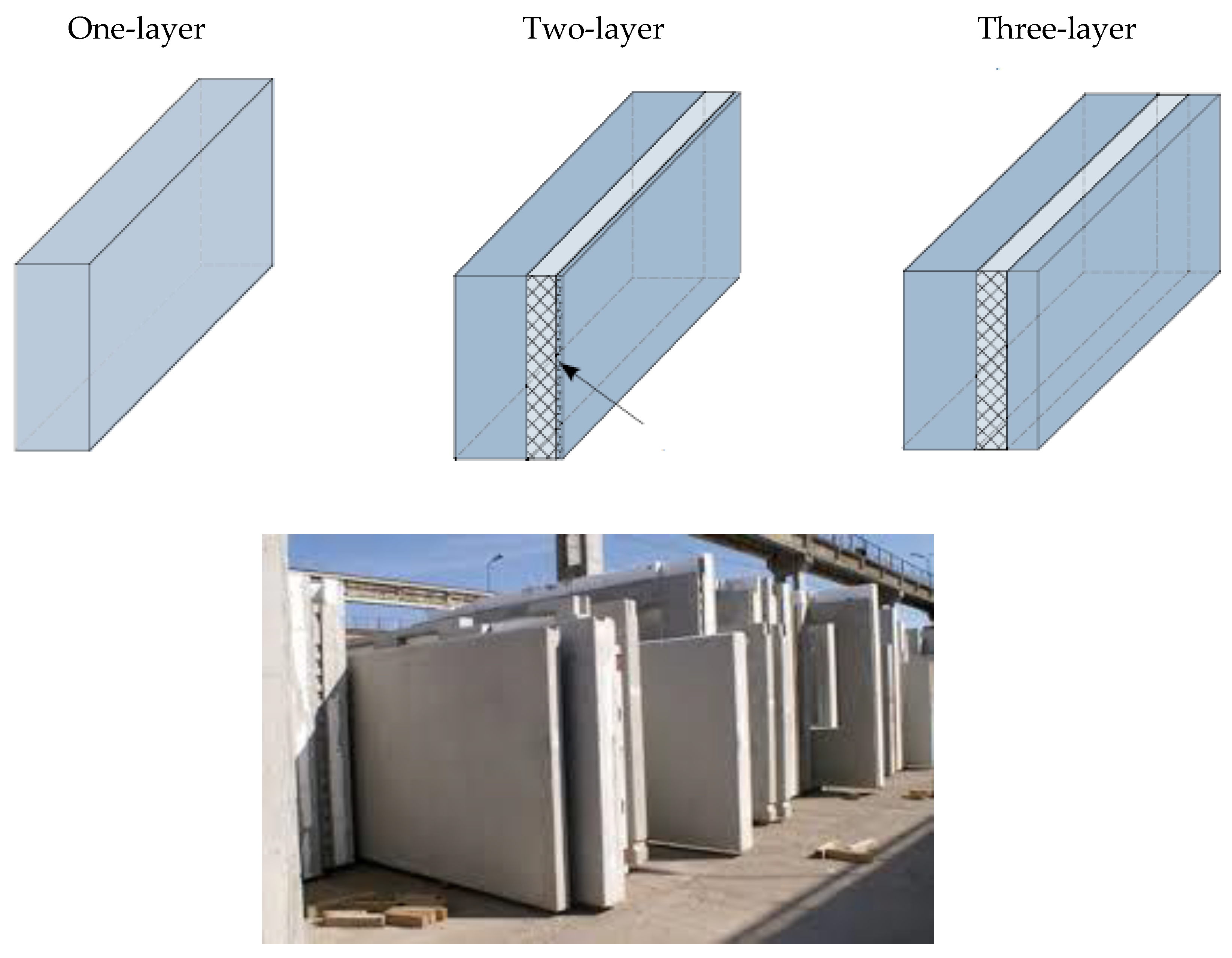
Figure 2 presents the types of prefabricated walls.
3. Results
3.1. Comparison of the Heat Transfer Coefficient through Outer Walls
The types of layers, thickness of the layers, the values of thermal conductivity coefficients, and thermal resistivity values were determined to compare and analyze the values of the heat transfer coefficients for the three types of a vertical outer wall. The walls with the ordinary concrete post and the post, made of concrete with expanded clay aggregate were compared, as well as the ones made of concrete with fly ash aggregate and with granulated foam glass aggregate.
3.2. Thermal Insulation
The total thermal resistivity RT of the flat construction component, consisting of homogeneous insulation layers, perpendicular to the direction of the heat flow should be calculated according to Equation (1).
where:
R1 = d1/λ1; R2 = d2/λ2; … Ri = di/λi
- d1, d2, … di—element thickness (cm)
- λ1, λ2, … λi—thermal conductivity coefficient (W/m·K)RT = Rsi + R1 + R2 +…..+ Ri + Rse
where:
- RT—total thermal resistivity (m2·K/W)
- Rsi—thermal resistance on the inner surface, (m2·K/W)
- R1, R2, … Ri—each layer’s thermal resistivity values, (m2·K/W)
- Rse—thermal resistance on the outer surface, (m2·K/W)
Heat transfer coefficient was calculated according to the Equation (3).
Heat transfer coefficient of the wall was calculated according to the Equation (4).
The main assumption was the maximum heat transfer coefficient Umax could not be higher than 0.2 (W/(m2·K)).
4. Discussion
The research of different variants of the project realization and the proposal of the optimal one leads to the choice of the best solution from the point of view of the chosen criterion. The aim of the alternative solution analysis is, among others, to answer the question, if the new technology or material implementation is beneficial from the investor’s/manufacturer’s point of view and if it leads to the cost reduction and/or production time saving [34,35]. In the construction branch, cost reduction and/or construction elements production time saving is most frequently obtained through the use of the relevant materials and through mounting process optimization, and, as a result, the overall time saving [36].
In order to optimize costs, it is advised to prepare construction cost estimation, including all costs calculation (labor, materials, equipment, indirect costs, and profit) for the solutions in question. In the case of time optimization, it is necessary to analyze workload for each process within the proposed solutions.
The objective of the analysis, presented in the following part of the article, is to compare the labor cost and time needed for mounting the elements of the construction. Three solutions have been proposed, for which the costs and time of realization were analyzed.
4.1. The Cost Analysis of the Facility Implementation in Prefabricated Technology
The object was selected, the bill of quantities was prepared, assumptions for calculation were made, and a cost-estimate calculation was carried out in order to determine the cost of raising a building in a raw state by means of prefabricated technology and the use of three types of materials. Three solutions were analyzed.
The aforementioned methods were applied on an actual construction site. Subsequently, the economic, environmental, and social benefits of prefabricated concrete application in residential construction were analyzed.
Solution 1 consists of assembling the object from prefabricated reinforced concrete elements, which are traditionally reinforced with two steel meshes from main bars ϕ10 mm every 10 cm (vertical reinforcement) and from distribution bars ϕ8 mm every 15 cm (horizontal reinforcement). A sandwich wall contains an insulating layer of polystyrene. In addition, the wall has elements for transporting and arranging elements. Table 5 provides detailed information.
Solution 2 is an assembly of the object, using prefabricated layered elements, with a lightweight concrete core of sintered and expanded clay (Leca). Wall elements are reinforced with two steel meshes from main bars ϕ10 mm every 15 cm (vertical reinforcement) and distribution bars ϕ6 mm, laid every 15 cm (horizontal reinforcement). In addition, the wall has transporting and arranging elements. Table 5 provides detailed information.
Solution 3 consists of assembling the object with sandwich elements with a lightweight concrete core from granulated expanded glass aggregate, with an insulating layer of ultra-light concrete containing perlite and granulated expanded glass aggregate from the outside. Gypsum plaster was used in the inside. The wall reinforcement was designed with the 8 mm main bars every 15 cm (vertical reinforcement) and with ϕ6 mm distribution bars being laid every 15 cm (horizontal reinforcement). In addition, lightweight reinforced polymer structural fiber reinforcement was used in the amount of 2 kg/m3. The wall has elements, which enable the transport and arrangement of elements. Table 5 provides detailed information.
In Table 5, one can see the examples of the walls alongside with heat transfer coefficient.
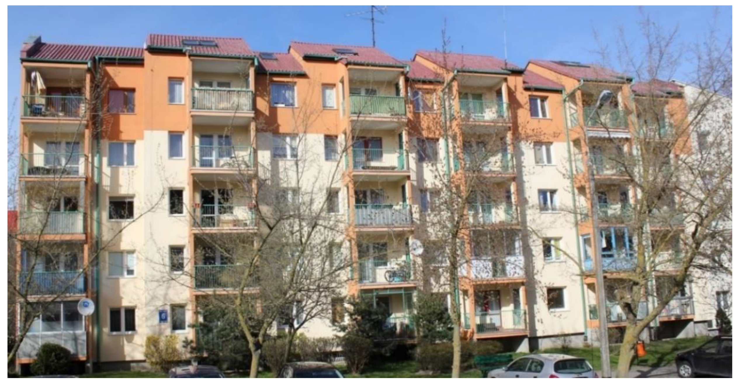
As an example, a multi-family, five-story, three-frame residential building was subjected to economic, technological, and organizational analysis (Figure 3). There are 30 residential premises with a total usable floor area of 1664.90 m2. The built-up area is 520.80 m2, the building has a cubature of 8900.60 m2, and the total area is 2983.40 m2 (including 76.20 m2 of service and technical rooms). The building is constructed of prefabricated elements in large-panel technology. The structural arrangement of the load-bearing walls is transverse, their spacing is 3.0 and 4.8 m. On the last storey of the building, masonry, prefabricated, and wet cast elements were used. Foundation benches are of reinforced concrete, wet cast from C30/37, concrete, and exposure class XC2. Structural walls of the underground and above-ground storeys are made of 15 cm thick prefabricated reinforced concrete elements.
On the basis of the project documentation, a bill of quantities (BOQ) was prepared, the range and quantity of certain works, needed for the raw object state, were determined. On that basis, an investor’s cost-estimate calculation was done in a simplified version. In both BOQ and estimation the production cost of the walls, ceilings and stairs were calculated (Table 6). The assessment was made on the basis of [37] and individual calculations [38]. It was assumed that, given retail prices would include labor, material, equipment costs, as well as indirect costs and profit for a mounting unit of each element [39]. For the walls, the retail prices concerned three proposed solutions (1–3). It was assumed that the production of the ceilings and stairs would be, in each case, as for solution 1 (prefabricated reinforced concrete).
Price per unit:
- Solution 1
- Prefabricated reinforced concrete (walls, ceilings and stairs): 486.42 monetary units
- Solution 2
- Prefabricated items from concrete products made of sintered and expanded clay aggregate (walls) and prefabricated reinforced concrete (ceilings and stairs): 494.75 monetary units
- Solution 3
- Prefabricated products that were made of lightweight concrete with GEGA (walls) and prefabricated reinforced concrete (ceilings and stairs): 512.87 monetary units.
Based on the cost calculation, prepared by means of the simplified method and prices from the third quarter of 2019 from the Sekocenbud price list [39] and producer prices, the cost of implementing the basic elements of the building’s raw state was made according to the three proposed solutions.
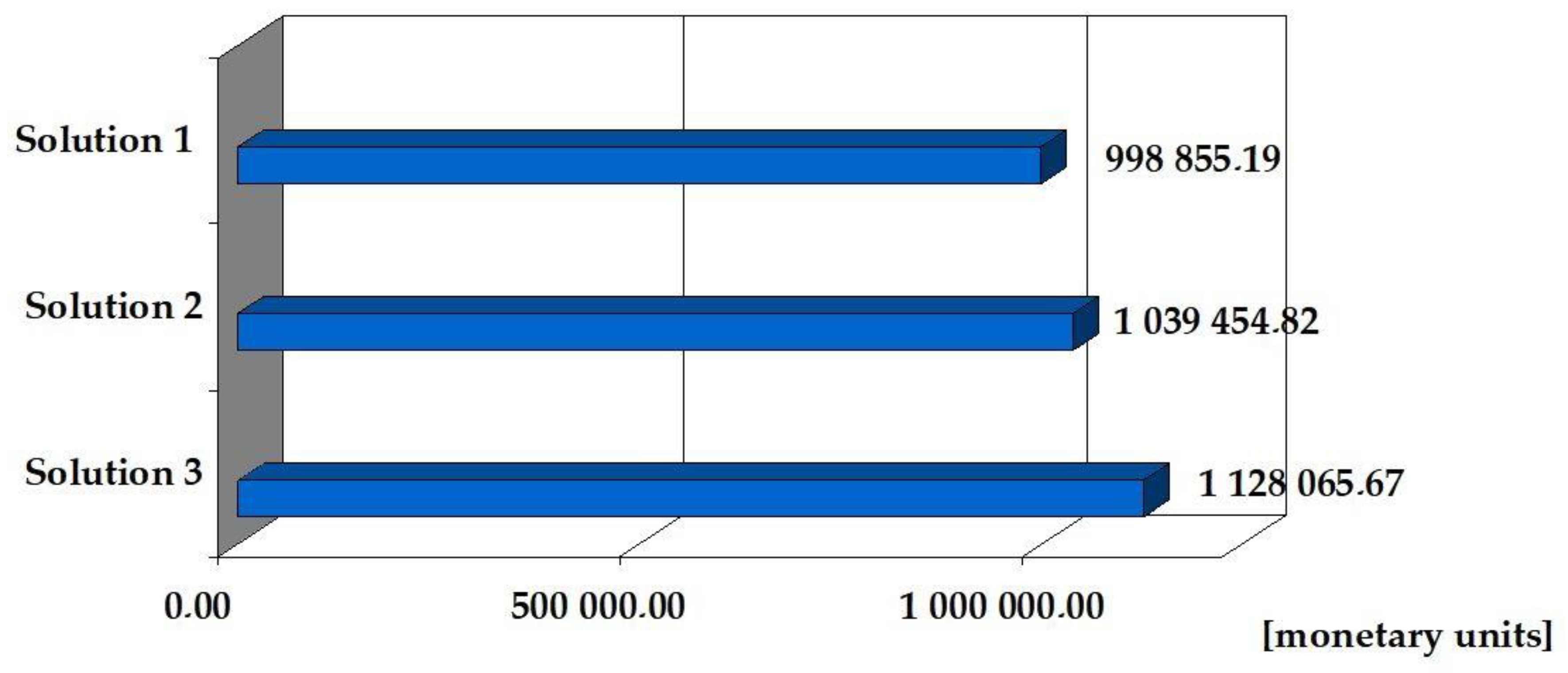
The cost of making the above range of the building shell (walls, ceilings, stairs) from reinforced concrete precast elements is 998,855.19 (monetary units). The cost of the same scope of works from precast lightweight concrete, which was made of sintered and expanded clay, is 1,039,454.82 (monetary units). The cost of prefabricated lightweight concrete works is 1,128,065.67 (monetary units). Solution No. 2 is 4.1% more expensive than solution No. 1, while solution No. 3 is more expensive than solution No. 1 by 12.9%. (Table 6, Figure 4).
4.2. The Analysis of Assembly Time
Table 7 presents a summary of the project’s implementation times according to the three proposed solutions. The following assumption was made: in each case, the construction of five floors of the building, five to 14 employees are employed (depending on the scope and nature of technological processes).
The expenditure of time given in Table 6 was determined on the basis of Material Expenditure Catalog KNR 2-02 [40] and own analyzes [38,41].
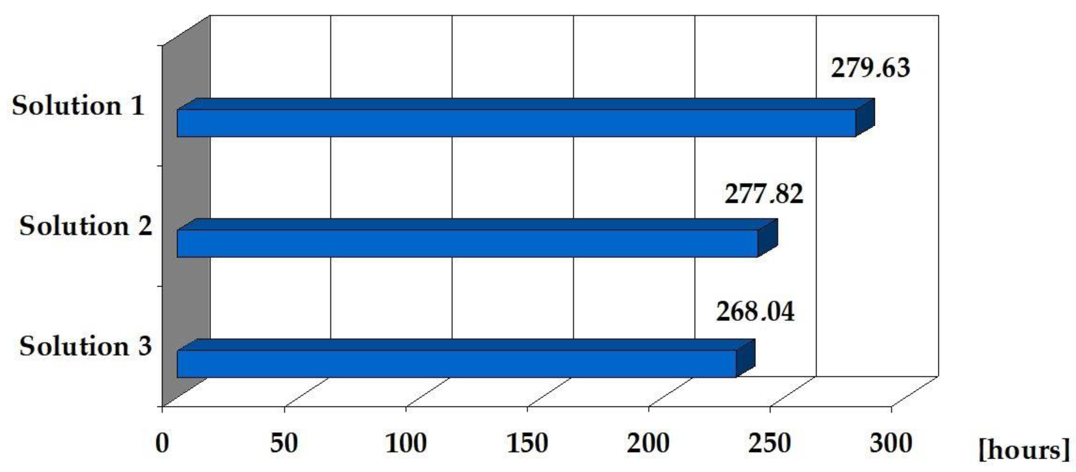
Based on the information contained in Table 7 and Figure 5, it can be concluded that the expenditure of working time for the technology of assembling the object according to solutions 2 and 3 are similar and significantly differ from the expenditure of time for solution 1. This is due to the fact that the structural elements—prefabricated concrete lightweight, made of sintered and expanded clay and lightweight concrete precast elements, made of GEGA, have similar weight and they are definitely lighter than reinforced concrete precasts. The assembly time of the object according to solution 3 is 4.3% shorter than the time resulting from solution 1.
5. Conclusions
The analysis, carried allows for formulating the following conclusions.
1. In practice, it is possible to use a prefabricated building, made of lightweight concrete, while maintaining all of the requirements for the construction of a building. This solution, in a broader context, finds technical and economic justification for its implementation in practice. It is possible to achieve time savings of up to 5% when compared to the assembly of a reinforced concrete precast object (solution 1).
2. The main advantage of using broadly defined prefabricated technology (compared to monolithic technology) is the significant time saving that results from the incorporation of ready-made construction products. The analysis, as presented in the article for the three solutions, involving the facility assembly from ready prefabricated elements, showed that, depending on the type of applied material, of which elements are made, it is possible to achieve a shorter implementation time of a given scope of construction works. With large-scale works, it is possible to achieve significant savings in investment implementation time. This applies to the prefabricated transport process to the construction site. It is possible to transport a larger number of them by the transport unit at one time due to the lower weight of the elements, made of lightweight concrete, which in turn also speeds up the delivery and assembly time on site, reduces fuel consumption, and achieves lower material transport costs. Solution 3, therefore, reduces investor’s expenses in this area and significantly increases the pace of works at the construction site. In practice, the choice of solution 1 from three presented ones is associated with the lowest cost for the investor, but the longest time of work performance—embedding prefabricated elements.
3. Solution 3 includes energy saving and the efficient use of raw materials in the production and assembly of prefabricated elements. It fully fits in with the idea of environmental protection and sustainable development of the economy [42,43]. Its use allows for reducing CO2 emissions in the process of manufacturing prefabricated elements and their transport to the construction site, and thus reduces environmental degradation [44]. The implementation of reinforced concrete precast elements (solution 1) requires greater energy consumption, which is necessary for producing a large amount of concrete mix. By using lightweight concrete, it is possible to use raw materials from the recycling of glass or fly ash. This significantly reduces environmental degradation [45,46], including large-scale mining of the aggregates.
4. The use of technology using solutions 2 and 3 affects the highest quality of performed work and ensures optimal thermal conductivity and fire resistance.
5. In construction practice, the integrated assembly of prefabricated elements, made of lightweight concrete, has not yet gained great interest. The numerous, also long-term benefits of using solution 3 should, however, encourage investors to choose and make extensive use of precast lightweight concrete, despite their higher price.
Author Contributions
Conceptualization, M.K. and B.G.; methodology, M.K. and A.K.; validation, B.G. and A.K.; formal analysis, M.K. and A.K.; investigation, B.G.; resources, A.K.; data curation, M.K.; writing—original draft preparation, M.K. and B.G.; writing—review and editing, A.K. and B.G.; visualization, M.K. and B.G.; supervision, A.K.; project administration, M.K.
Funding
This research received no external funding.
Conflicts of Interest
The authors declare no conflict of interest.
References
- PN-EN 206:2013+A1:2016 Concrete. Specification, Performance, Production and Conformity. Available online: https://0-shop-bsigroup-com.brum.beds.ac.uk/ProductDetail/?pid=000000000030326195 (accessed on 31 December 2013).
- Oktay, H.; Yumrutas, R.; Akpolat, A. Mechanical and thermal properties of lightweight aggregate concretes. Constr. Build. Mater. 2015, 96, 217–225. [Google Scholar] [CrossRef]
- Chandra, S.; Berntsson, L. Lightweight Aggregate Concrete. Science, Technology and Applications; Noyes Publications: Norwich, UK; New York, NY, USA, 2002; ISBN 0-8155-1486-7. [Google Scholar]
- Šeputytė-Jucikė, J.; Sinica, M. The effect of expanded glass and polystyrene waste on the properties of lightweight aggregate concrete. Eng. Struct. Technol. 2016, 8, 31–40. [Google Scholar] [CrossRef]
- Ünal, O.; Uygunoglu, T.; Yildiz, A. Investigation of properties of low-strength lightweight concrete for thermal insulation. Build. Environ. 2007, 42, 584–590. [Google Scholar] [CrossRef]
- Krishnamoorthy, R.R.; Zujip, J.A. Thermal conductivity and microstructure of concrete using recycle glass as a fine aggregate replacement. Int. J. Adv. Res. Technol. 2013, 3, 463–471. [Google Scholar]
- Kurpińska, M. Properties of concrete impregnated using epoxy composition. Roads Bridges-Drog. Mosty 2011, 10, 59–80. [Google Scholar]
- Bumanis, G.; Bajare, D.; Korjakins, A. Mechanical and thermal properties of lightweight concrete made from expanded glass. J. Sustain. Arch. Civ. Eng. 2013, 2, 26–32. [Google Scholar] [CrossRef]
- Omidimoaf, E.; Rajabi, A.M.; Abdelgader, H.S.; Kurpińska, M.; Wilde, K. Effect of coarse grain aggregate on strength parameters of two-stage concrete. Mater. Bud. 2019, 3, 1–3. [Google Scholar] [CrossRef]
- Rumsys, D.; Spudulis, E.; Bacinskas, D.; Kaklauskas, G. Compressive Strenght and Durability Properties Structural Lightweight Concrete with Fine Expanded Class and/or Clay Aggregates. Materials 2018, 11, 2434. [Google Scholar] [CrossRef] [PubMed]
- Ke, Y.; Beaucor, A.L.; Ortola, S.; Dumontet, H.; Cabrillac, R. Influence of volume fraction and characteristics of lightweight aggregates on the mechanical properties of concrete. Constr. Build. Mater. 2009, 23, 2821–2828. [Google Scholar] [CrossRef]
- Kurpińska, M.; Ferenc, T. Effect of porosity on physical properties of lightweight cement composite with foamed glass aggregate. In Proceedings of the II International Conference of Computational Methods in Engineering Science (CMES’2017), Lublin, Poland, 23–25 November 2017. [Google Scholar]
- Lo, T.Y.; Tang, W.C.; Cui, H.Z. The effects of aggregate properties on lightweight concrete. Build. Environ. 2007, 42, 3025–3029. [Google Scholar] [CrossRef]
- Wang, J.Y.; Chia, K.S.; Liew, J.Y.R.; Zhang, M.H. Flexural performance of fiber-reinforced ultra-lightweight cement composites with low fiber content. Cem. Concr. Compos. 2013, 43, 39–47. [Google Scholar] [CrossRef]
- Kristowski, A.; Grzyl, B.; Kurpińska, M.; Pszczoła, M. The rigid and flexible road pavements in terms of life cycle costs. In Proceedings of the Creative Construction Conference 2018, Ljubljana, Slovenia, 30 June–3 July 2018. [Google Scholar] [CrossRef]
- Limbachiya, M.; Meddah, M.; Fotiadou, S. Performance of granulated foam glass concrete. Constr. Build. Mater. 2012, 28, 759–768. [Google Scholar] [CrossRef]
- Khatib, J.M.; Shariff, S.; Negim, E.M. Effect of incorporating foamed glass on the flexural behaviour of reinforced concrete beams. World Appl. Sci. J. 2012, 19, 47–51. [Google Scholar]
- Chung, S.Y.; Abd Elrahman, M.; Sikora, P.; Rucinska, T.; Horszczaruk, E.; Stephan, D. Evaluation of the Effects of Crushed and Expanded Waste Glass Aggregates on the Material Properties of Lightweight Concrete Using Image-Based Approaches. Materials 2017, 10, 1354. [Google Scholar] [CrossRef] [PubMed]
- Kurpińska, M.; Ferenc, T. Application of lightweight cement composite with foamed glass aggregate in shell structures. Shell Struct. Theory Appl. 2018, 4, 549–552. [Google Scholar]
- Kurpinska, M.; Kułak, L. Predicting Performance of Lightweight Concrete with Granulated Expanded Glass and Ash Aggregate by Means of Using Artificial Neural Networks. Materials 2019, 12, 2002. [Google Scholar] [CrossRef]
- Kralj, D. Experimental study of recycling lightweight concrete with aggregates containing expanded glass. Process. Saf. Environ. Prot. 2006, 87, 267–273. [Google Scholar] [CrossRef]
- Brückner, T.; Fuchs, A.; Wistlich, L.; Hoess, A.; Nies, B.; Gbureck, U. Prefabricated and Self-Setting Cement Laminates. Materials 2019, 12, 834. [Google Scholar] [CrossRef]
- Liu, S.; Wang, S.; Tang, W.; Hu, N.; Wei, J. Inhibitory E_ect of waste Glass Powder on ASR Expansion Induced by Waste Glass Aggregate Materials. Materials 2015, 8, 6849–6862. [Google Scholar] [CrossRef]
- Jamshidi, A.; Kurumisawa, K.; Nawa, T.; Igarashi, T. Performance of pavements incorporating waste glass: The current state of the art. Renew. Sustain. Energy Rev. 2016, 64, 211–236. [Google Scholar] [CrossRef]
- Mariak, A.; Kurpińska, M.; Wilde, K. Maturity curve for estimating the in-place strength of high performance concrete. MATEC Web Conf. 2019, 262, 06007. [Google Scholar] [CrossRef]
- Mariak, A.; Kurpińska, M. The effect of macro polymer fibres length and content on the fibre reinforced concrete. MATEC Web Conf. 2018, 219, 03004. [Google Scholar] [CrossRef]
- Gong, T.; Yang, J.; Hu, H.; Xu, F. Construction Technology of Off-Site Precast Concrete Buildings. Front. Eng. Manag. 2015, 2, 122. [Google Scholar] [CrossRef]
- Pons, O.; Oliva, J.M.; Maas, S.R. Improving the Learning Process in the Latest Prefabricated School Buildings. Improv. Sch. 2010, 13, 249–265. [Google Scholar] [CrossRef]
- Cao, X.; Li, X.; Zhu, Y.; Zhang, Z. A comparative study of environmental performance between prefabricated and traditional residential buildings in China. J. Clean. Prod. 2015, 109, 131–143. [Google Scholar] [CrossRef]
- Jiao, L.; Li, X.D. Application of Prefabricated Concrete in Residential Buildings and its Safety Management. Arch. Civ. Eng. 2018, 64, 21–35. [Google Scholar] [CrossRef] [Green Version]
- PN-EN 12524:2000. Building Materials and Products. Hygrothermal Properties. Tabulated Design Values; ISO: Geneva, Switzerland, 2000. [Google Scholar]
- PN-EN ISO 6946:2017. Building Components and Building Elements. Thermal Resistance and Thermal Transmittance. Calculation Methods; ISO: Geneva, Switzerland, 2017. [Google Scholar]
- PN-EN 12831-1:2017. Energy Performance of Buildings. Method for Calculation of the Design Heat Load. Space Heating Load, Module M3-3; ISO: Geneva, Switzerland, 2017. [Google Scholar]
- Mostafa, K.G.; Montemagno, C.; Qureshi, A.J. Strength to cost ratio analysis of FDM Nylon 12 3D Printed Parts. Procedia Manuf. 2018, 26, 753–762. [Google Scholar] [CrossRef]
- Khosravani, M.R.; Nasiri, S.; Weinberg, K. Application of case-based reasoning in a fault detection system on production of drippers. Appl. Soft Comput. 2019, 75, 227–232. [Google Scholar] [CrossRef]
- Leśniak, A.; Zima, K. Cost calculation of construction projects including sustainability factors using the Case Based Reasoning (CBR) method. Sustainability 2018, 10, 1608. [Google Scholar] [CrossRef]
- Resolution of the Minister of Infrastructure of May 18, 2004 on Determining the Methods and Grounds for Preparing an Investor’s Cost Estimate, Calculating Planned Costs of Design Works and Planned Costs of Construction Works Specified in the Functional and Utility Program. Available online: http://prawo.sejm.gov.pl/isap.nsf/DocDetails.xsp?id=WDU20041301389 (accessed on 3 November 2019).
- Grzyl, B.; Kristowski, A. A calculation proposal of labour time input when concreting in difficult atmospheric conditions. Czas. Tech. 2014, 2014, 203–208. [Google Scholar]
- Ośrodek Wdrożeń Ekonomiczno-Organizacyjnych Budownictwa PROMOCJA Sp. z o.o. Bulletin of Prices for Investment Construction Works, III Term 2019; OWEOB Promotion Sp.z o.o.: Warszawa, Poland, 2019. [Google Scholar]
- Wacetob. Katalog Nakładów Rzeczowych nr 2-02; Wacetob: Warszawa, Poland, 2017. [Google Scholar]
- Leśniak, A.; Plebankiewicz, E.; Zima, K. Cost calculation of building structures and building works in Polish conditions. Eng. Manag. Res. 2012, 1, 72–81. [Google Scholar] [CrossRef]
- Grzyl, B.; Siemaszko, A. The Life Cycle Assessment and Life Cycle Cost in public works contracts. E3S Web Conf. 2018, 44, 00047. [Google Scholar] [CrossRef] [Green Version]
- Grzyl, B.; Kristowski, A.; Jamroz, K.; Gobis, A. Methods of estimating the cost of traffic safety equipment’s life cycle. MATEC Web Conf. 2017, 122, 02003. [Google Scholar] [CrossRef]
- Grzyl, B.; Miszewska-Urbańska, E.; Apollo, M. The life cycle cost of a building from the point of view of environmental criteria of selecting the most beneficial offer in the area of competitive tendering. E3S Web Conf. 2017, 17, 00028. [Google Scholar] [CrossRef] [Green Version]
- Kowalski, D.; Grzyl, B.; Kristowski, A. The cost analysis of corrosion protection solutions for steel components in terms of the object life cycle cost. Civ. Environ. Eng. Rep. 2017, 26, 5–13. [Google Scholar] [CrossRef]
- Plebankiewicz, E.; Zima, K.; Wieczorek, D. Life cycle cost modelling of buildings with consideration of the risk. Arch. Civ. Eng. 2016, 62, 149–166. [Google Scholar] [CrossRef]
Figure 1.
Process of manufacturing of prefabricated wall elements [30].
Figure 1.
Process of manufacturing of prefabricated wall elements [30].

Figure 2.
Prefabricated elements storage.

Figure 3.
A multi-family, five-story, three-frame residential building. Source: own photo of the authors.
Figure 3.
A multi-family, five-story, three-frame residential building. Source: own photo of the authors.

Figure 4.
Cost of making walls, ceilings and stairs in the building implemented according to three solutions.
Figure 4.
Cost of making walls, ceilings and stairs in the building implemented according to three solutions.

Figure 5.
Time of processing walls, ceilings, and stairs in the building to be implemented according to three solutions.
Figure 5.
Time of processing walls, ceilings, and stairs in the building to be implemented according to three solutions.


Table 1.
Comparison between on-site and off-site construction based on [26].
Table 1.
Comparison between on-site and off-site construction based on [26].
| On-Site Construction | Off-Site Construction | |
|---|---|---|
| Labor/time | Labor work intensive. Longer time for construction. | Technology intensive. Shorter time for construction. |
| Environmental independence | Remarkably influenced by the ambient temperature and other factors. | Prefabricated components can be directly assembled on site. |
| Quality control | Hard to find an agreed standard for various situations. | Quality can be easily controlled, the elements are repeatable. |
| Shape flexibility | On-site construction is often applied for buildings with complicated designs. | Buildings are relatively alike due to fixed scale. |
| Construction management | Complex management of material stocking, human resources and safety. | Transport of the materials and their stocking can be reduced. |
| Resource consumption | Low efficiency of resource usage. Huge energy consumption. | Industrialization of components increases the efficiency of resource usage. A specified factory is usually needed. |
| Environmental friendliness | Noise and pollution influence the environment greatly. | Rare noise and pollution, hence, more environmentally friendly. |
| Construction function | Special procedures need to be applied for water and fire protection. Lower construction efficiency. | Components of specified functions are precast in factory, which reduces difficulties. |
| Structure performance | Better performance in integrality and stability. | Relatively weaker in stability and earthquake-resistance if we use ordinary concrete and better if we use lightweight concrete. |
Table 2.
The values of the heat transfer coefficient U (W/m2·K) for the walls of the residential buildings, determined for weather conditions in Poland (according to Ministerial Order §134 art. 2).
Table 2.
The values of the heat transfer coefficient U (W/m2·K) for the walls of the residential buildings, determined for weather conditions in Poland (according to Ministerial Order §134 art. 2).
| Kind of the Wall and Indoor Temperature | Heat Transfer Coefficient Umax (W/m2·K) |
|---|---|
| Outer walls (exposed to the outdoor air) (a) at ti >16 °C (b) at ti ≤ 16 °C where: ti—indoor temperature | 0.3 0.8 |
| Inner walls between the heated and unheated rooms, staircases and corridors | 1.0 |
Table 3.
Values for calculation of physical properties of the selected materials.
| Material | Density in a Dry State ρ (kg/m3) | Thermal Conductivity Coefficient λ (W/m·K) |
|---|---|---|
| Ordinary concrete | 2200 | 1.30 |
| Ordinary concrete with steel rebar (2%) | 2400 | 1.70 |
| Concrete with expanded clay aggregate | 1000 | 0.39 |
| 1100 | 0.46 | |
| 1200 | 0.54 | |
| 1300 | 0.62 | |
| 1400 | 0.72 | |
| 1600 | 0.90 | |
| Concrete with granulaed foam glass aggregate and sand * | 1000 | 0.39 |
| Concrete with granulated foam glass aggregate and perlite with dispersed fiber reinforcement | 600 | 0.38 |
| 800 | 0.46 | |
| 1000 | 0.51 | |
| Concrete with granulaed foam glass aggregate and granilated sintered fly ash aggregate * | 1000 | 0.54 |
| 1200 | 0.60 | |
| 1400 | 0.67 | |
| 1600 | 0.74 | |
| Styrofoam (EPS) | 12 | 0.045 |
| 15 | 0.043 | |
| 20 | 0.040 | |
| Mineral wool | 50 | 0.038 |
| 90 | 0.039 | |
| 130 | 0.040 | |
| Cement-lime plaster | 1850 | 0.90 |
| Gypsum plaster | 1000 | 0.40 |
| 600 | 0.18 | |
| Air | 1.23 | 0.025 |
* Authors’ own research.
Table 4.
Values of the thermal resistance Rsi, Rse.
| Thermal Resistance | Direction of the Heat Flow | ||
|---|---|---|---|
| Horizontal | Horizontal (up) | Vertical (down) | |
| Rsi (m2·K/W) | 0.13 | 0.10 | 0.17 |
| Rse (m2·K/W) | 0.04 | ||
Table 5.
Heat transfer coefficients for an outer multilayer wall.
| Element Sort | Layer Sort | Material Density | Layer Thickness | Thermal Conductivity Coeficient for the Material λ | Layer Thermal Resistivity Ri | Heat Transfer Coefficient for the Wall U | Weight for Wall’s Dimentions (6 × 3 m2) |
|---|---|---|---|---|---|---|---|
| (kg/m3) | (m) | (W/m2·K) | (W/m2·K) | (W/(m2·K)) | (kg) | ||
| Ordinary concrete wall Class C20/25 (wall thickness 39 cm) | Rse | - | - | - | 0.04 | 0.20 | 7524.4 |
| Cement-lime plaser | 1850 | 0.015 | 0.82 | 0.02 | |||
| Ordinary concrete with a rebar | 2400 | 0.15 | 1.7 | 0.09 | |||
| Styrofoam | 12 | 0.21 | 0.045 | 4.67 | |||
| Cement-lime plaser | 1850 | 0.015 | 0.82 | 0.02 | |||
| Rsi | - | - | - | 0.13 | |||
| Lightweight concrete wall with expanded clay aggregate and natural sand LC 20/22 (wall thickness 43 cm) | Rse | - | - | - | 0.04 | 0.20 | 6228.4 |
| Cement-lime plaser | 1850 | 0.015 | 0.82 | 0.02 | |||
| Concrete with expanded clay aggregate (1600) | 1600 | 0.18 | 0.9 | 0.20 | |||
| Styrofoam | 12 | 0.21 | 0.045 | 4.67 | |||
| Cement-lime plaser. | 1850 | 0.015 | 0.82 | 0.02 | |||
| Rsi | - | - | - | 0.13 | |||
| Lightweight concrete wall with granulated foam glass aggregate LC 20/22 (wall thickness 41.5 cm) | Rse | - | - | - | 0.04 | 0.20 | 4705.2 |
| Lightweight insulation concrete with granulated foam glass aggregate and perlite (800) | 800 | 0.05 | 0.46 | 0.11 | |||
| styrofoam | 12 | 0.2 | 0.045 | 4.44 | |||
| Lightweight concrete with granulated foam glass aggregate and fly ash aggregate (400) | 1400 | 0.15 | 0.67 | 0.22 | |||
| Gypsum plaster (600) | 600 | 0.01 | 0.18 | 0.06 | |||
| Rsi | - | - | - | 0.13 |
Table 6.
List of structural elements for five storeys of the building, unit prices and total cost of walls, ceilings and stairs according to solutions 1, 2, 3.
Table 6.
List of structural elements for five storeys of the building, unit prices and total cost of walls, ceilings and stairs according to solutions 1, 2, 3.
| Type of Item | Number (m2) or (pcs) of Elements of a Given Type on a Typical Story | Number (m2) or (pcs) of Elements of a Given Type in the Building | Solution 1 Prefabricated Reinforced Concrete | Solution 2 Prefabricated Items from Concrete Products Made of Sintered and Expanded Clay Aggreate | Solution 3 Prefabricated Products Made of Lightweight Concrete with GEGA | |||
|---|---|---|---|---|---|---|---|---|
| Price per Unit (Monetary Units) | Total Cost (Monetary Units) | Price per Unit (Monetary Units) | Total Cost (Monetary Units) | Price per Unit (Monetary Units) | Total Cost (Monetary Units) | |||
| (1) | (2) | (3) | (4) | (5) = (3) × (4) | (6) | (7) = (3) × (6) | (8) | (9) = (3) × (8) |
| External load-bearing walls | 57.50 (m2) | 287.50 (m2) | 247.49 | 71,153.38 | 264.22 | 75,963.25 | 300.74 | 86,462.75 |
| Outer curtain walls | 216.00 (m2) | 1089.00 (m2) | 226.01 | 246,124.89 | 241.29 | 262,764.81 | 274.64 | 299,082.96 |
| Internal load-bearing walls | 220.30 (m2) | 1101.50 (m2) | 233.57 | 257,277.36 | 249.36 | 274,670.04 | 283.82 | 312,627.73 |
| Internal partition walls | 33.63 (m2) | 168.15 (m2) | 154.58 | 25,992.63 | 165.03 | 27,749.79 | 187.84 | 31,585.30 |
| Ceiling with wreaths | 416.80 (m2) | 2084.00 (m2) | 159.52 | 332,439.68 | 159.52 | 332,439.68 | 159.52 | 332,439.68 |
| Stairs—running boards | 6 (pcs) | 30 (pcs) | 2007.35 | 60,220.50 | 2007.35 | 60,220.50 | 2007.35 | 60,220.50 |
| Stairs—landing plates | 3 (pcs) | 15 (pcs) | 376.45 | 5646.75 | 376.45 | 5646.75 | 376.45 | 5646.75 |
| Sum: 998,855.19 (monetary units) | Sum: 1,039,454.82 (monetary units) | Sum: 1,128,065.67 (monetary units) | ||||||
Table 7.
Time analysis—assembly of prefabricated elements according to three solutions.
| Type of item | Number (m2) or (pcs) of Elements of a Given Type on a Typical Story | Number (m2) or (pcs) of Elements of a Given Type in the Building | Solution 1 Prefabricated Reinforced Concrete | Solution 2 Prefabricated Items from Concrete Products Made of Sintered and Expanded Clay Aggregate | Solution 3 Prefabricated Products Made of Lightweight Concrete with GEGA | ||||||
|---|---|---|---|---|---|---|---|---|---|---|---|
| Working Time per Work Unit [r-g]* | Working Time per Work Unit [m-g]* | Total Assembly Time (h) | Working Time per Work Unit [r-g]* | Working Time per Work unit [m-g]* | Total Assembly Time (h) | Working Time per Work Unit [r-g]* | Working Time per Work Unit [r-g]* | Total Assembly Time (h) | |||
| (1) | (2) | (3) | (4) | (5) | (6) | (7) | (8) | (9) | (10) | (11) | (12) |
| External load-bearing walls | 57.50 (m2) | 287.50 (m2) | 0.172 | 0.051 | 14.21 | 0.170 | 0.050 | 14.00 | 0.157 | 0.042 | 12.21 |
| Outer curtain walls | 216.00 (m2) | 1089.00 (m2) | 0.165 | 0.042 | 45.94 | 0.153 | 0.040 | 45.20 | 0.148 | 0.036 | 43.81 |
| Internal load-bearing walls | 220.30 (m2) | 1101.50 (m2) | 0.165 | 0.042 | 44.95 | 0.165 | 0.040 | 44.15 | 0.155 | 0.036 | 42.82 |
| Internal partition walls | 33.63 (m2) | 168.15 (m2) | 0.143 | 0.041 | 7.11 | 0.140 | 0.040 | 7.05 | 0.125 | 0.037 | 6.79 |
| Ceiling with wreaths | 416.80 (m2) | 2084.00 (m2) | 1.180 | 0.063 | 150.20 | 1.180 | 0.063 | 150.20 | 1.180 | 0.063 | 150.20 |
| Stairs—running boards | 6 (pcs) | 30 (pcs) | 1.053 | 0.374 | 12.21 | 1.053 | 0.374 | 12.21 | 1.053 | 0.374 | 12.21 |
| Stairs—landing plates | 3 (pcs) | 15 (pcs) | 0.752 | 0.330 | 5.01 | 0.752 | 0.330 | 5.01 | 0.752 | 0.330 | 5.01 |
| Sum: 279.63 (h) | Sum: 277.82 (h) | Sum: 268.04 (h) | |||||||||
[r-g]*—man hours; [m-g]*—machine hours.
© 2019 by the authors. Licensee MDPI, Basel, Switzerland. This article is an open access article distributed under the terms and conditions of the Creative Commons Attribution (CC BY) license (http://creativecommons.org/licenses/by/4.0/).
Share and Cite
MDPI and ACS Style
Kurpinska, M.; Grzyl, B.; Kristowski, A. Cost Analysis of Prefabricated Elements of the Ordinary and Lightweight Concrete Walls in Residential Construction. Materials 2019, 12, 3629. https://0-doi-org.brum.beds.ac.uk/10.3390/ma12213629
AMA Style
Kurpinska M, Grzyl B, Kristowski A. Cost Analysis of Prefabricated Elements of the Ordinary and Lightweight Concrete Walls in Residential Construction. Materials. 2019; 12(21):3629. https://0-doi-org.brum.beds.ac.uk/10.3390/ma12213629
Chicago/Turabian StyleKurpinska, Marzena, Beata Grzyl, and Adam Kristowski. 2019. "Cost Analysis of Prefabricated Elements of the Ordinary and Lightweight Concrete Walls in Residential Construction" Materials 12, no. 21: 3629. https://0-doi-org.brum.beds.ac.uk/10.3390/ma12213629
Note that from the first issue of 2016, this journal uses article numbers instead of page numbers. See further details here.