Electron Irradiation Effects on Strength and Ductility of Polymer Foils Studied by Femtosecond Laser-Processed Micro-Tensile Specimens


Abstract
:
1. Introduction
2. Experimental
2.1. Materials
- Polyimide Upilex-S VDA (25.4 m-thickness) from UBE
- PET (Polyethylene terephthalate) (127 m) from Sheldahl
- FEP (Fluorinated ethylene propylene) VDA (127 m) from Sheldahl
Electron Irradiation Procedure
2.2. Methods
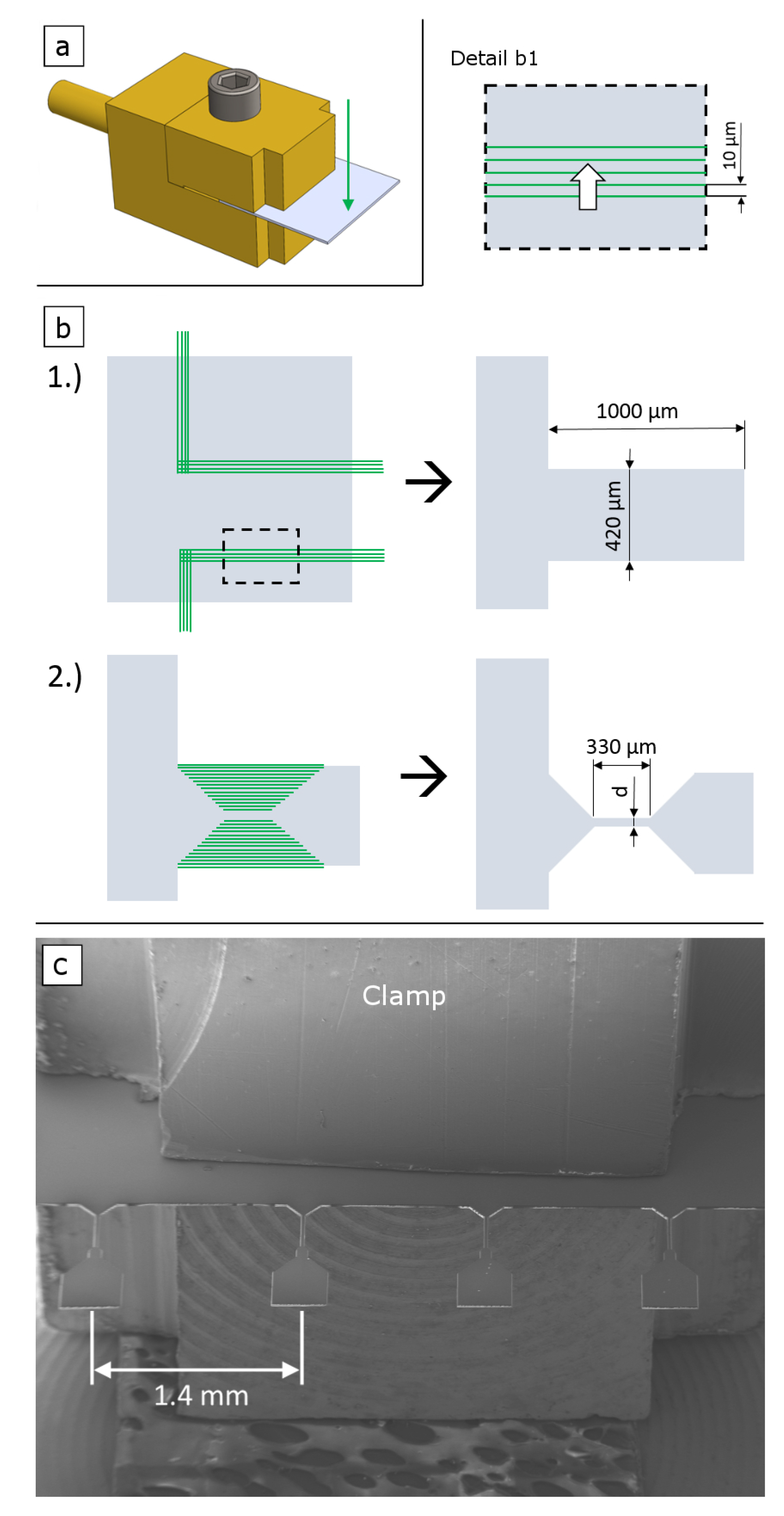
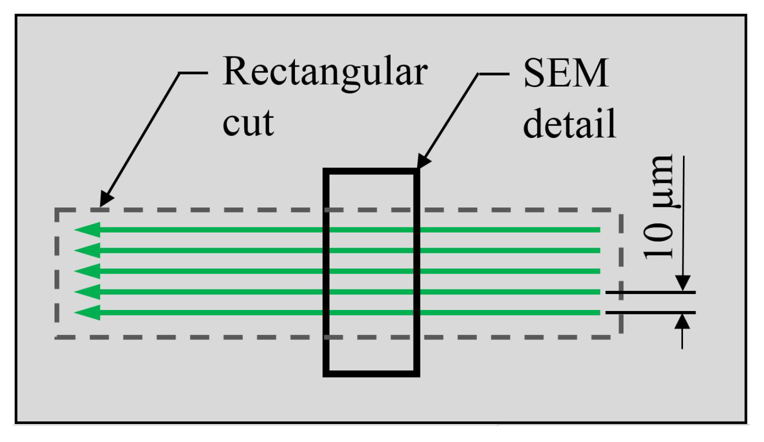
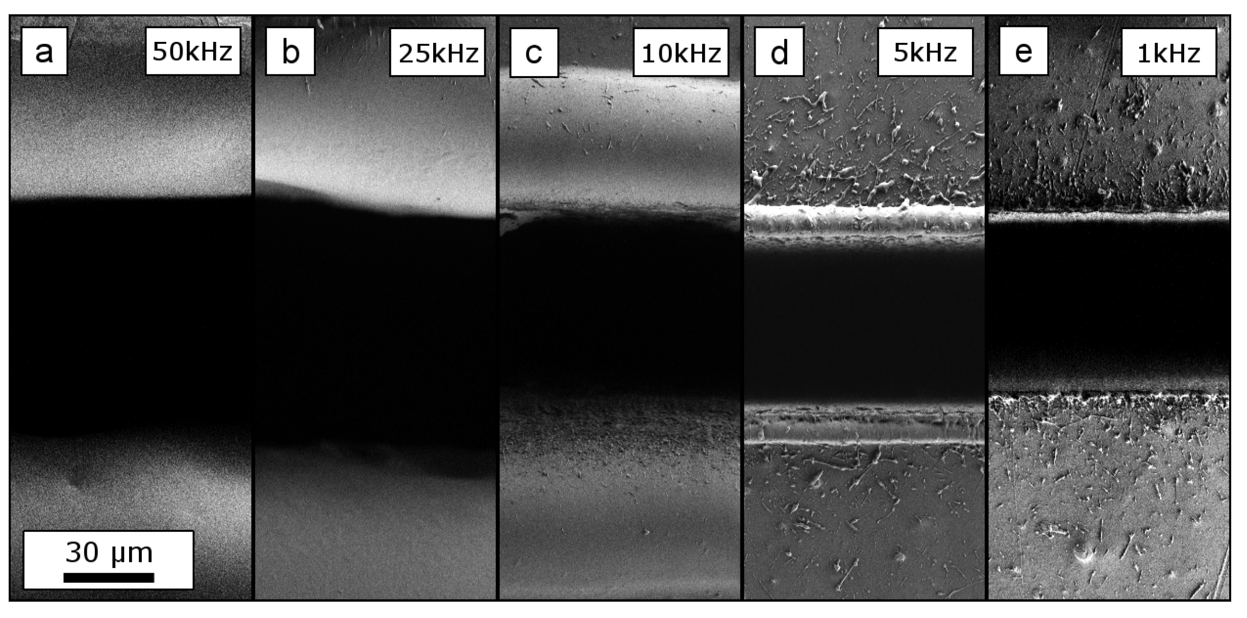
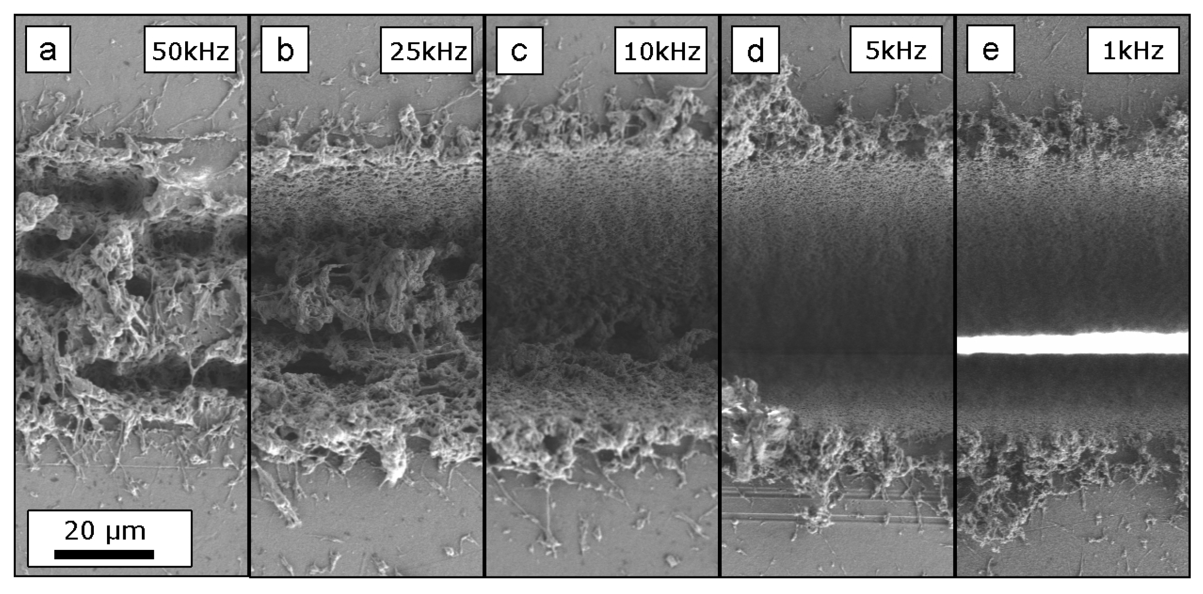
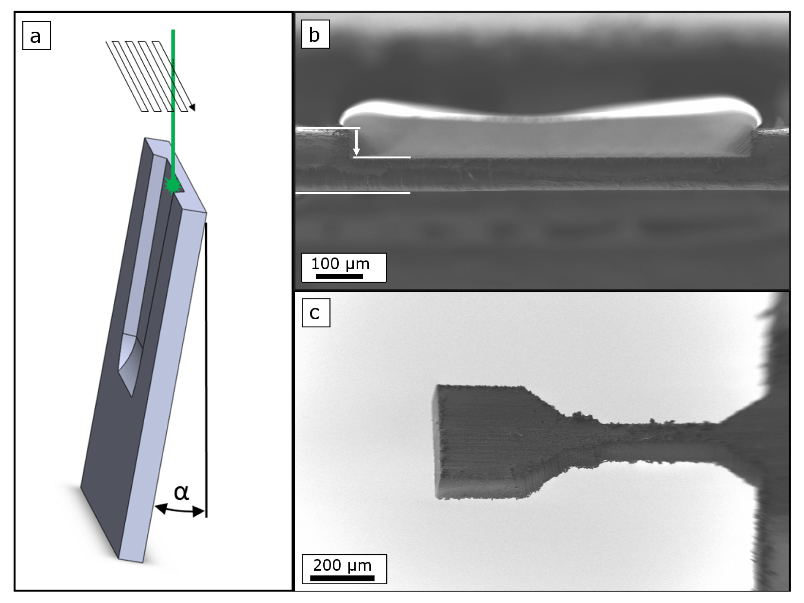
2.2.1. Laser Processing
2.2.2. Setup of Tensile Experiments
3. Results and Discussion
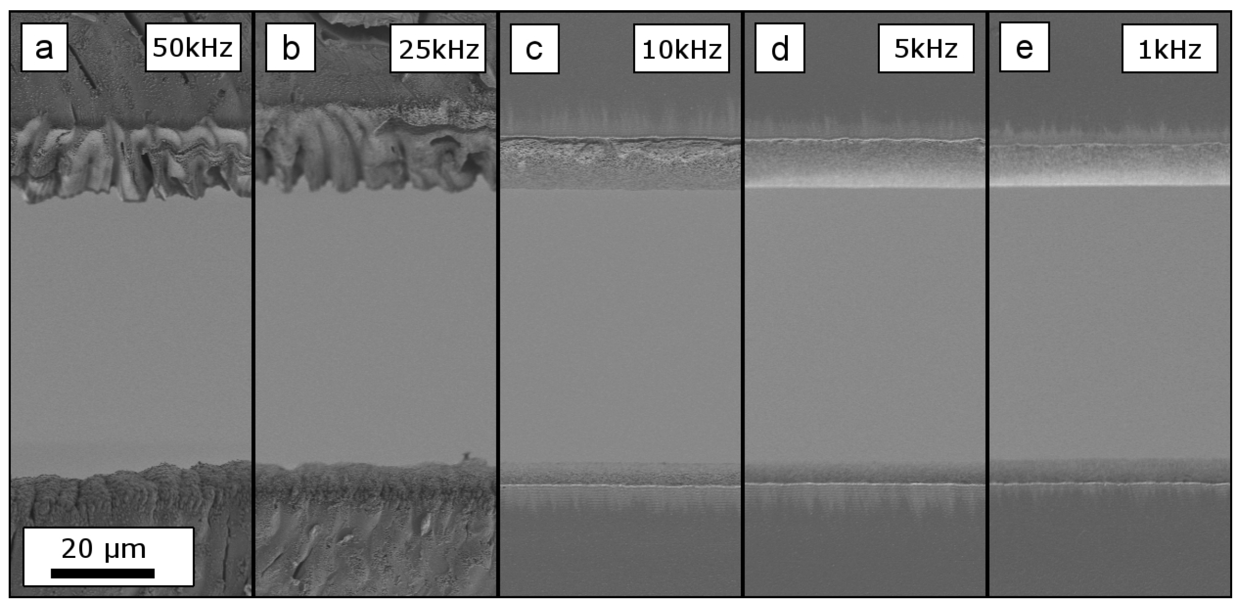
3.1. Influence of fs-Laser Processing
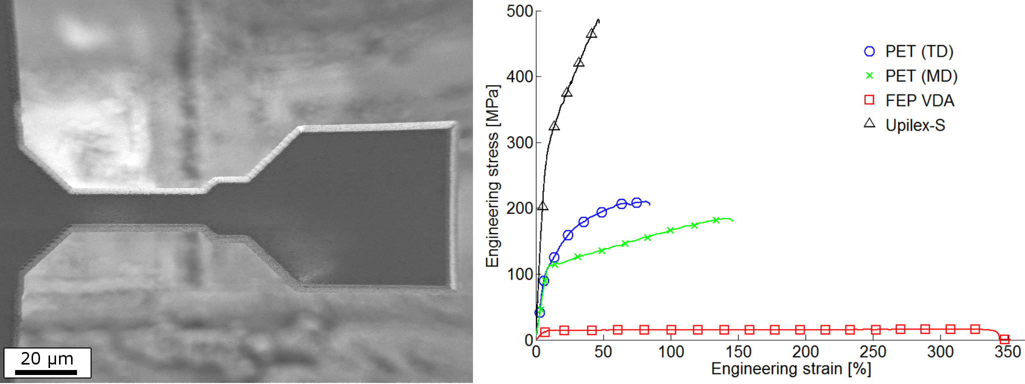
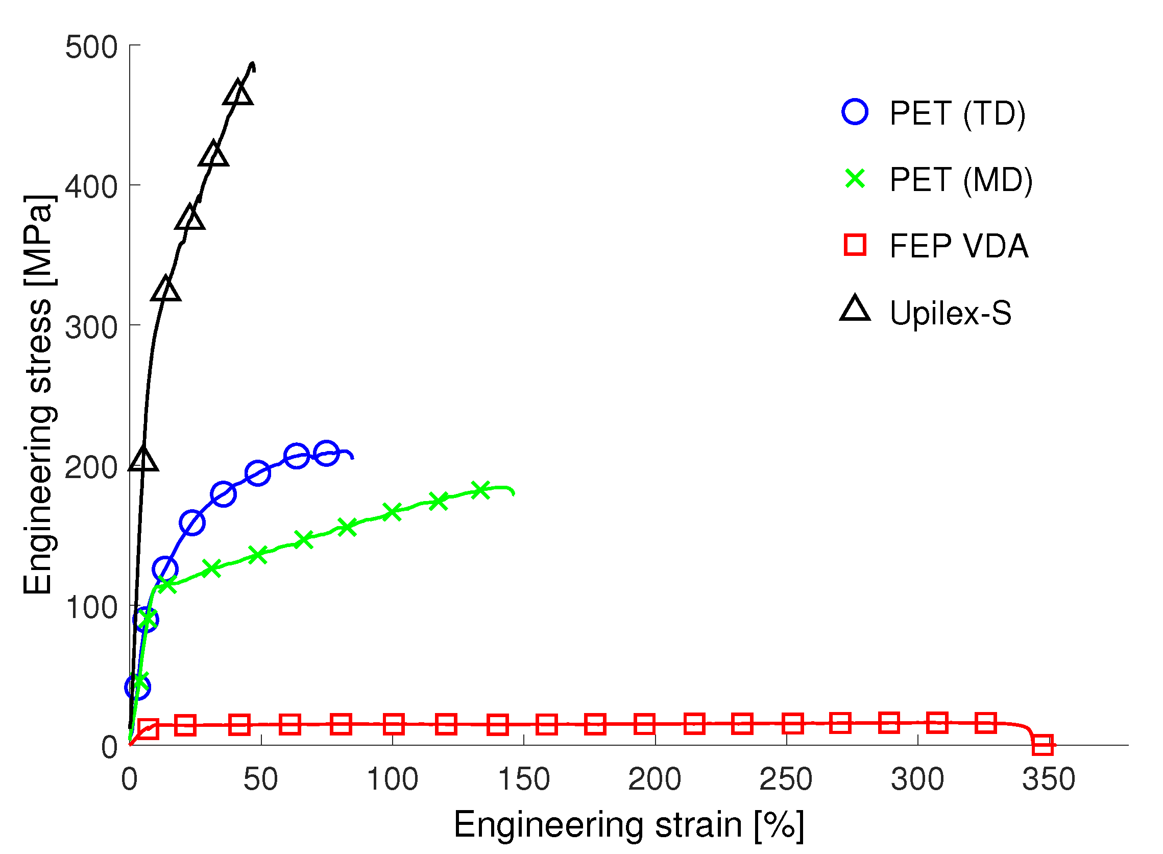
3.2. Tensile Experiments
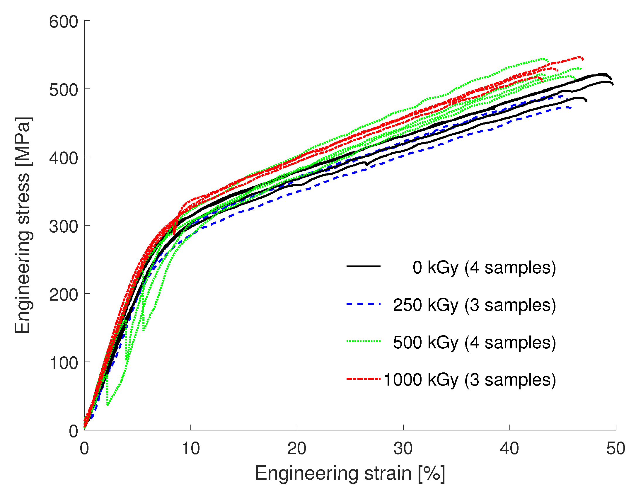
3.3. Influence of Electron Beam Irradiation
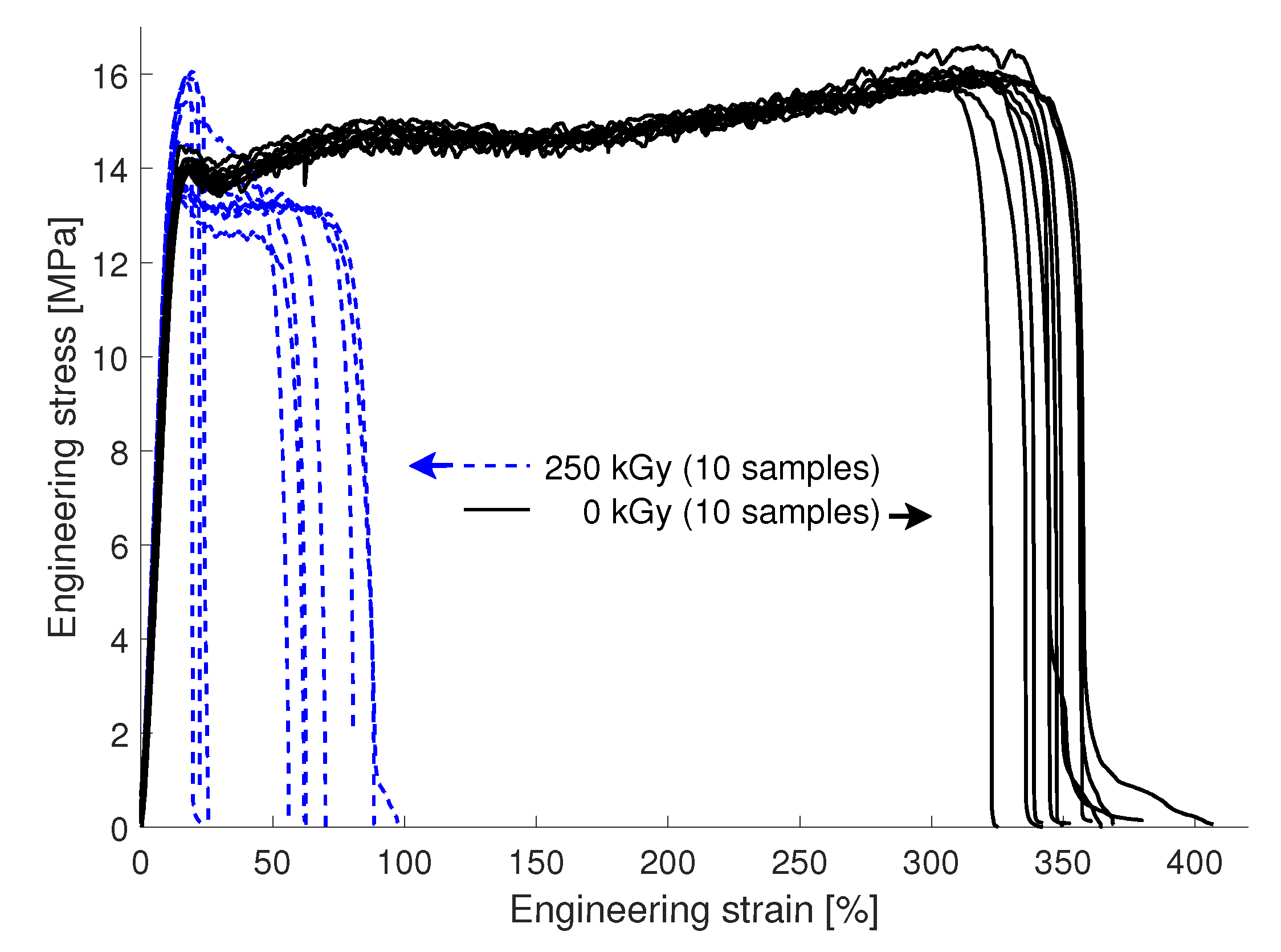
3.3.1. Upilex-S VDA
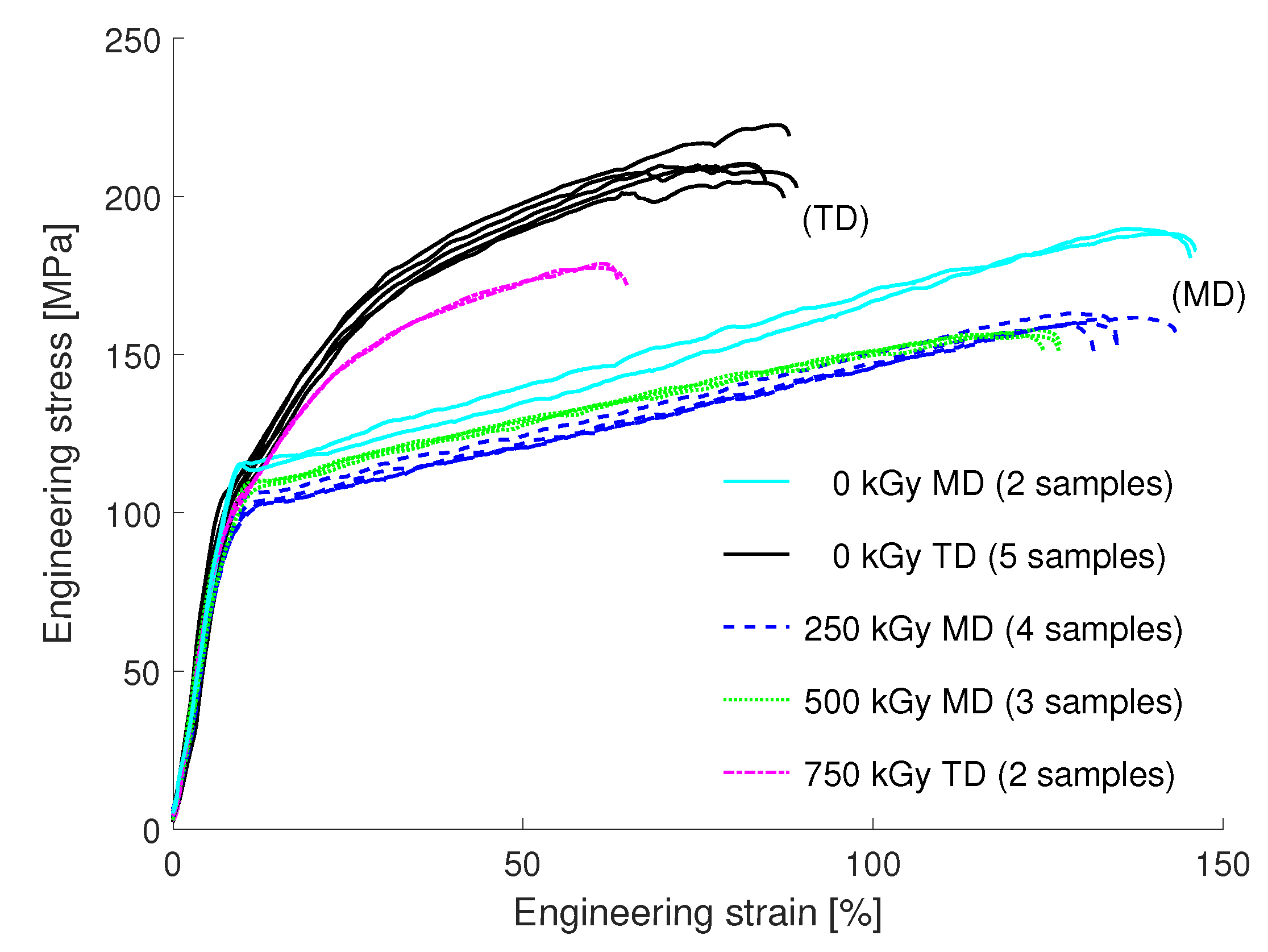
3.3.2. PET
3.3.3. FEP VDA
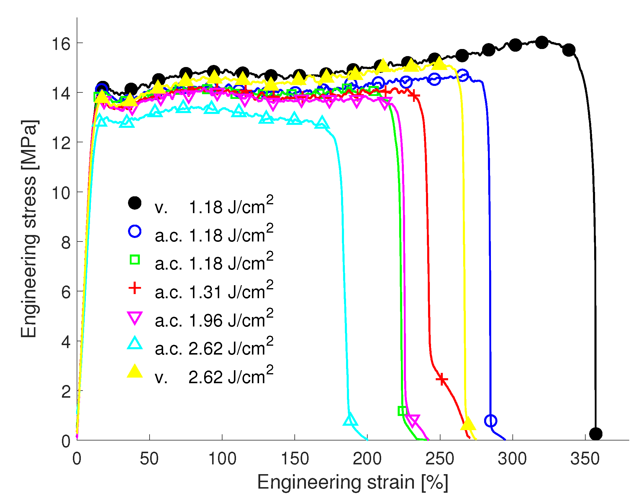
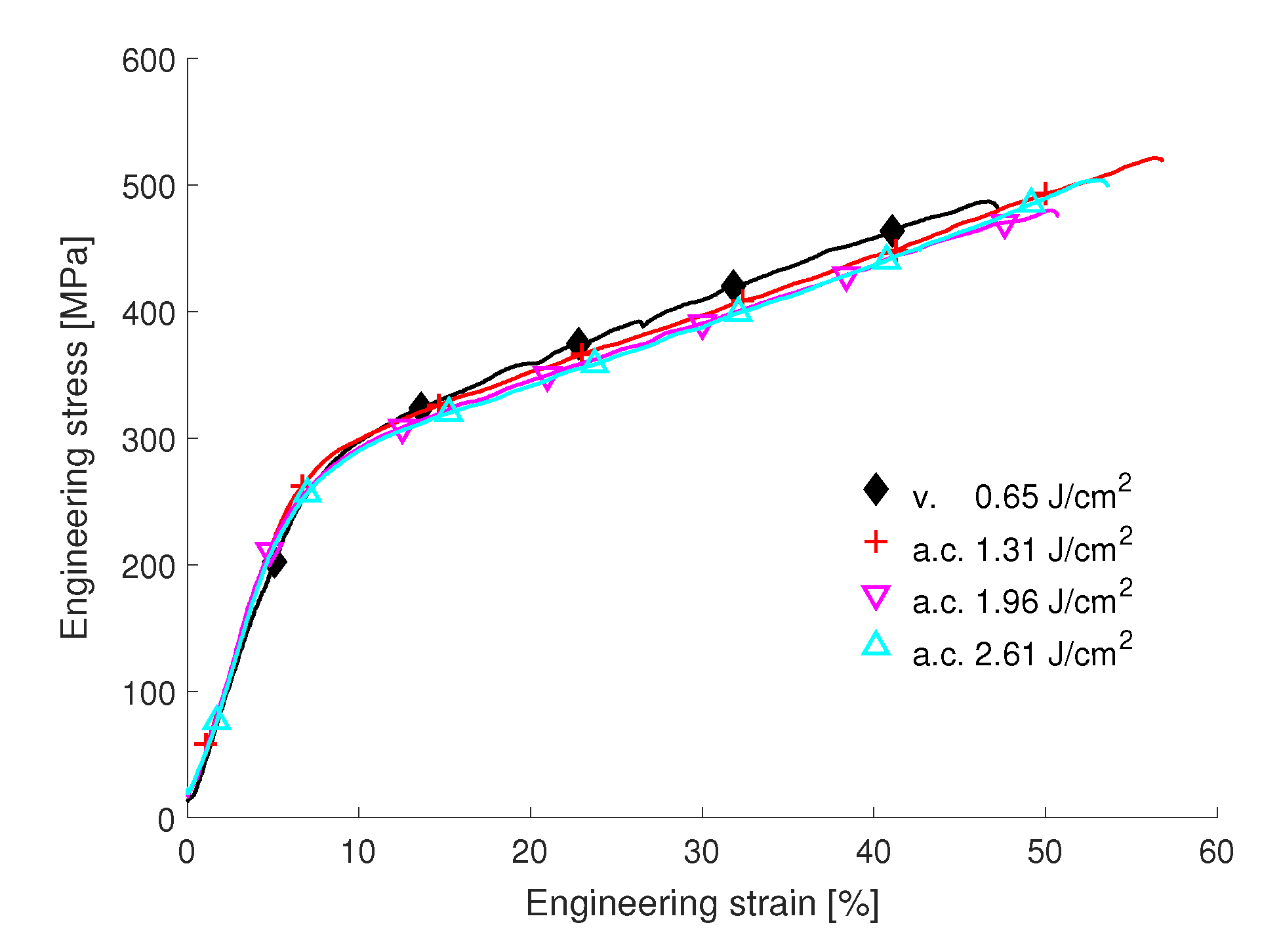
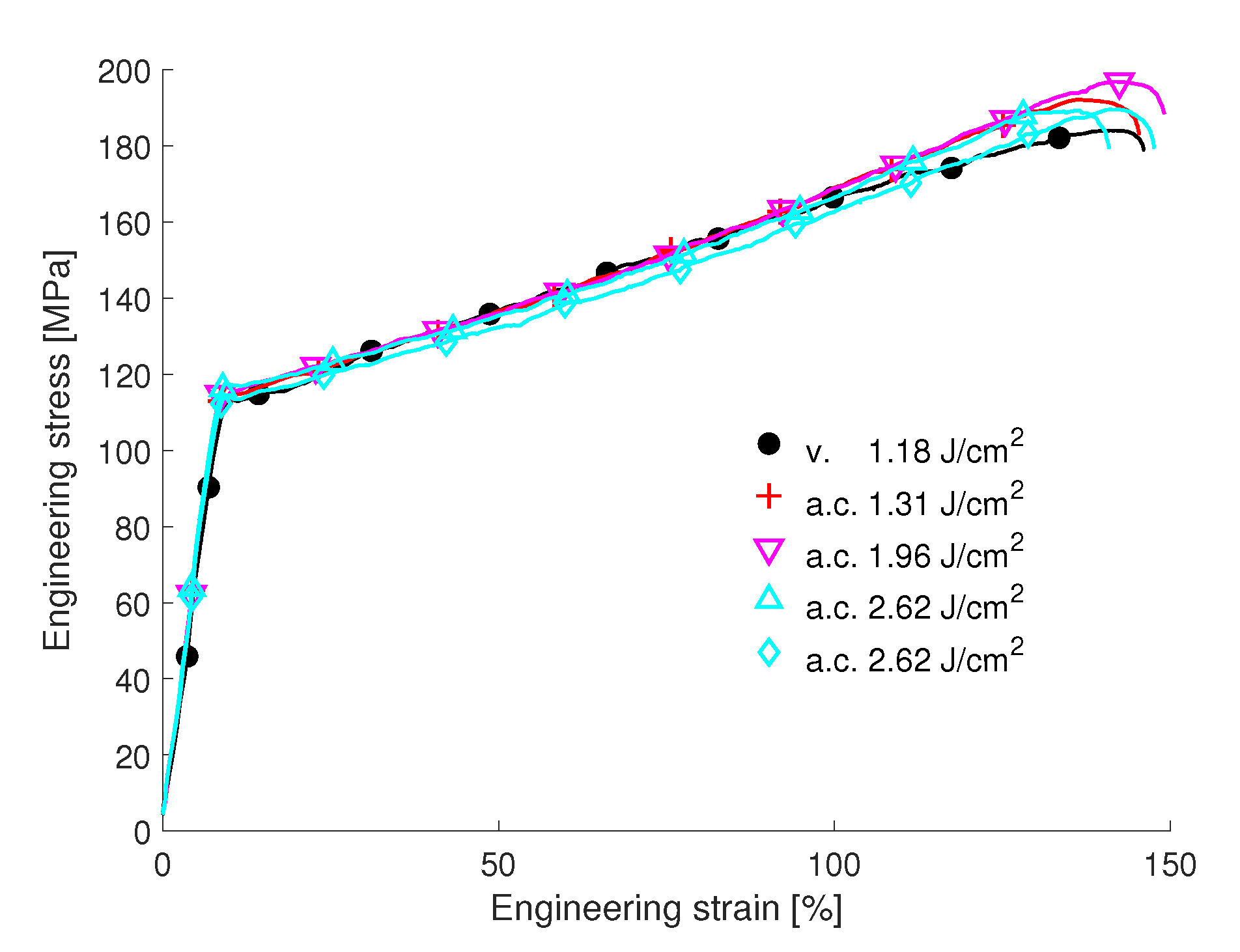
3.4. Influence of fs-Laser Processing Atmosphere
4. Outlook—Local Thinning of the Polymer Foil
5. Conclusions
Author Contributions
Funding
Acknowledgments
Conflicts of Interest
Appendix A


References
- Townsend, J.A.; Hansen, P.A.; Dever, J.A.; de Groh, K.K.; Banks, B.A.; Wang, L.; He, C. Hubble Space Telescope Metallized Teflon® FEP thermal Control Materials: On-Orbit Degradation and Post-Retrieval Analysis. High Perform. Polym. 1999, 11, 81–99. [Google Scholar] [CrossRef]
- Townsend, J.A.; Powers, C.E.; Viens, M.J.; Ayres-Treusdell, M.T.; Munoz, B.F. Degradation of Teflon® FEP Following Charged Particle Radiation and Rapid Thermal Cycling. In Proceedings of the 20th Space Simulation Conference, Annapolis, MD, USA, 27–29 October 1998. [Google Scholar]
- Semprimoschnig, C.O.A.; Heltzel, S.; Polsak, A.; Van Eesbeek, M. Space Environmental Testing of Thermal Control Foils at Extreme Temperatures. High Perform. Polym. 2004, 16, 207–220. [Google Scholar] [CrossRef]
- Sasuga, T.; Hayakawa, N.; Yoshida, K.; Hagiwara, M. Degradation in tensile properties of aromatic polymers by electron beam irradiation. Polymer 1985, 26, 1039–1045. [Google Scholar] [CrossRef]
- Dever, J.A.; de Groh, K.K.; Banks, B.A.; Townsend, J.A. Effects of Radiation and Thermal Cycling on Teflon® FEP. High Perform. Polym. 1999, 11, 123–140. [Google Scholar] [CrossRef]
- Moser, M.; Ranzenberger, C.; Duzellier, S. Space Environmental Testing of Novel Candidate Materials for Multilayer Insulation. J. Spacecr. Rocket. 2016, 53, 1134–1140. [Google Scholar] [CrossRef]
- Moser, M.; Semprimoschnig, C.O.A.; Van Eesbeek, M.; Pippan, R. Comparison of results from post-flight investigations on FEP retrieved from the Hubble Space Telescope solar arrays and LDEF. In Proceedings of the European Conference on Spacecraft Structures, Noordwijk, The Netherlands, 10–12 May 2005; Volume 581, p. 95. [Google Scholar]
- Shimamura, H.; Yamagata, I. Degradation of Mechanical Properties of Polyimide Film Exposed to Space Environment. J. Spacecr. Rocket. 2009, 46, 15–21. [Google Scholar] [CrossRef]
- Chen, J.; Ding, N.; Li, Z.; Wang, W. Organic polymer materials in the space environment. Prog. Aerosp. Sci. 2016, 83, 37–56. [Google Scholar] [CrossRef]
- Dever, J.A.; Miller, S.K.; Sechkar, E.A.; Wittberg, T.N. Space Environment Exposure of Polymer Films on the Materials International Space Station Experiment: Results from MISSE 1 and MISSE 2. High Perform. Polym. 2008, 20, 371–387. [Google Scholar] [CrossRef]
- ASTM. ASTM D882-18, Standard Test Method for Tensile Properties of Thin Plastic Sheeting; ASTM: West Conshohocken, PA, USA, 2018. [Google Scholar]
- Nolte, S.; Momma, C.; Jacobs, H.; Tünnermann, A.; Chichkov, B.N.; Wellegehausen, B.; Welling, H. Ablation of metals by ultrashort laser pulses. J. Opt. Soc. Am. B 1997, 14, 2716–2722. [Google Scholar] [CrossRef]
- Shirk, M.D.; Molian, P.A. A review of ultrashort pulsed laser ablation of materials. J. Laser Appl. 1998, 10, 18–28. [Google Scholar] [CrossRef]
- Krüger, J.; Kautek, W. Ultrashort Pulse Laser Interaction with Dielectrics and Polymers. In Polymers and Light; Lippert, T.K., Ed.; Advances in Polymer Science; Springer: Berlin/Heidelberg, Germany, 2004; pp. 247–290. [Google Scholar]
- Mohd Abbas, N.; Solomon, D.G.; Fuad Bahari, M. A review on current research trends in electrical discharge machining (EDM). Int. J. Mach. Tools Manuf. 2007, 47, 1214–1228. [Google Scholar] [CrossRef]
- Chichkov, B.N.; Momma, C.; Nolte, S.; Alvensleben, F.V.; Tünnermann, A. Femtosecond, picosecond and nanosecond laser ablation of solids. Appl. Phys. A 1996, 63, 109–115. [Google Scholar] [CrossRef]
- ASM International. ISTFA 2013: Proceedings from the 39th International Symposium for Testing and Failure Analysis; ASM International: Geauga, OH, USA, 2013. [Google Scholar]
- Slaughter, S.K.; Ligda, J.P.; Sano, T.; Schuster, B.E. High Throughput Femtosecond-Laser Machining of Micro-Tension Specimens. In Proceedings of the TMS 2015 144th Annual Meeting & Exhibition, Orlando, FL, USA, 15–19 March 2015; Springer: Cham, Switzerland, 2015; pp. 471–478. [Google Scholar]
- Jakob, S.; Pfeifenberger, M.J.; Hohenwarter, A.; Pippan, R. Femtosecond laser machining for characterization of local mechanical properties of biomaterials: A case study on wood. Sci. Technol. Adv. Mater. 2017, 18, 574–583. [Google Scholar] [CrossRef]
- Magagnosc, D.J.; Ligda, J.P.; Sano, T.; Schuster, B.E. Femtosecond Laser Machining of Micro-tensile Specimens for High Throughput Mechanical Testing. In Micro and Nanomechanics; Conference Proceedings of the Society for Experimental Mechanics Series; Springer: Cham, Switzerland, 2018; Volume 5, pp. 7–9. [Google Scholar]
- de Groh, K.K.; Banks, B.A.; Miller, S.K.R.; Dever, J.A. Chapter 28—Degradation of Spacecraft Materials. In Handbook of Environmental Degradation of Materials, 3rd ed.; Kutz, M., Ed.; William Andrew Publishing: Norwich, NY, USA, 2018; pp. 601–645. [Google Scholar]
- Pfeifenberger, M.J.; Mangang, M.; Wurster, S.; Reiser, J.; Hohenwarter, A.; Pfleging, W.; Kiener, D.; Pippan, R. The use of femtosecond laser ablation as a novel tool for rapid micro-mechanical sample preparation. Mater. Des. 2017, 121, 109–118. [Google Scholar] [CrossRef]
- Yang, S.Y. (Ed.) Advanced Polyimide Materials: Synthesis, Characterization, and Applications, 1st ed.; Elsevier: Amsterdam, The Netherlands, 2018. [Google Scholar]
- de Groh, K.K.; Waters, D.; Mohammed, J.; Perry, B.; Banks, B. Analyses of Hubble Space Telescope Aluminized-Teflon Insulation Retrieved After 19 Years of Space Exposure. In Protection of Materials and Structures From the Space Environment, Astrophysics and Space Science Proceedings; Springer-Verlag: Berlin/Heidelberg, Germany, 2013; Volume 32, pp. 13–26. [Google Scholar]
- Kumagai, H.; Midorikawa, K.; Toyoda, K.; Nakamura, S.; Okamoto, T.; Obara, M. Ablation of polymer films by a femtosecond high peak power Ti:sapphire laser at 798 nm. Appl. Phys. Lett. 1994, 65, 1850–1852. [Google Scholar] [CrossRef]
- Yang, B.; Motz, C.; Grosinger, W.; Kammrath, W.; Dehm, G. Tensile behaviour of micro-sized copper wires studied using a novel fibre tensile module. Int. J. Mater. Res. 2008, 99, 716–724. [Google Scholar] [CrossRef]
- Nolte, S.; Schrempel, F.; Dausinger, F. Ultrashort Pulse Laser Technology: Laser Sources and Applications, 1st ed.; Springer: Cham, Switzerland, 2015. [Google Scholar]
- Eaton, S.M.; Zhang, H.; Herman, P.R.; Yoshino, F.; Shah, L.; Bovatsek, J.; Arai, A.Y. Heat accumulation effects in femtosecond laser-written waveguides with variable repetition rate. Opt. Express 2005, 13, 4708–4716. [Google Scholar] [CrossRef]
- Michler, G.H.; Baltá Calleja, F.J. Nano- and Micromechanics of Polymers: Structure Modification and Improvement of Properties; Carl Hanser Verlag GmbH & Co. KG: Cincinnati, OH, USA, 2012. [Google Scholar]
- Semprimoschnig, C.O.A.; Gray, P.; Nehls, M.K.; Edwards, D.L. Accelerated space environmental testing and analysis of ultra-thin polymer films for Gossamer space structures like solar sails. In Proceedings of the 10th International Symposium on Materials in a Space Environment, Colliour, France, 19–23 June 2006; Volume SP-616. [Google Scholar]
- Poluektov, M.; Dommelen, J.A.W.; Govaert, L.E.; Geers, M.G.D. Characterisation and modelling of anisotropic thermo-mechanical behaviour of oriented polyethylene terephthalate. Model. Simul. Mater. Sci. Eng. 2014, 22, 055024. [Google Scholar] [CrossRef]
- Źenkiewicz, M. Effects of electron-beam irradiation on some mechanical properties of polymer films. Radiat. Phys. Chem. 2004, 69, 373–378. [Google Scholar] [CrossRef]
- Wang, Z.B.; Hong, M.H.; Lu, Y.F.; Wu, D.J.; Lan, B.; Chong, T.C. Femtosecond laser ablation of polytetrafluoroethylene (Teflon) in ambient air. J. Appl. Phys. 2003, 93, 6375–6380. [Google Scholar] [CrossRef]
- Wang, Y.; Wang, X.; Zhang, N.; Zhai, H.; Zhu, X. Study of ambient air ionization with femtosecond laser pulses. Proc. SPIE 2005, 5627, 105–111. [Google Scholar]


| Irradiation Dose [kGy] | 0 | 250 | 500 | 750 | 1000 |
|---|---|---|---|---|---|
| Upilex-S VDA | ∘ | ∘ | ∘ | ∘ | |
| PET | ∘ | ∘ | ∘ | ∘ | |
| FEP VDA | ∘ | ∘ |
| Upilex-S | FEP | PET | |
|---|---|---|---|
| VDA | VDA | ||
| Fluence [J/cm] | 0.65 | 1.18 | 1.18 |
| Pulse rep. rate [kHz] | 1 | 1 | 1 |
| Scan speed [mm/s] | 2 | 2 | 2 |
| Scan repetitions [−] | 15 | 40 | 40 |
| Processing time [s] | ≈380 | ≈1000 | ≈1000 |
| Taper angle [] |
© 2019 by the authors. Licensee MDPI, Basel, Switzerland. This article is an open access article distributed under the terms and conditions of the Creative Commons Attribution (CC BY) license (http://creativecommons.org/licenses/by/4.0/).
Share and Cite
Pfeifenberger, M.J.; Milassin, G.; Hohenwarter, A.; Putz, B.; Semprimoschnig, C.O.A.; Pippan, R. Electron Irradiation Effects on Strength and Ductility of Polymer Foils Studied by Femtosecond Laser-Processed Micro-Tensile Specimens. Materials 2019, 12, 1468. https://0-doi-org.brum.beds.ac.uk/10.3390/ma12091468
Pfeifenberger MJ, Milassin G, Hohenwarter A, Putz B, Semprimoschnig COA, Pippan R. Electron Irradiation Effects on Strength and Ductility of Polymer Foils Studied by Femtosecond Laser-Processed Micro-Tensile Specimens. Materials. 2019; 12(9):1468. https://0-doi-org.brum.beds.ac.uk/10.3390/ma12091468
Chicago/Turabian StylePfeifenberger, Manuel J., Gabor Milassin, Anton Hohenwarter, Barbara Putz, Christopher O. A. Semprimoschnig, and Reinhard Pippan. 2019. "Electron Irradiation Effects on Strength and Ductility of Polymer Foils Studied by Femtosecond Laser-Processed Micro-Tensile Specimens" Materials 12, no. 9: 1468. https://0-doi-org.brum.beds.ac.uk/10.3390/ma12091468