Quasi-Solid-State Electrochromic Cells with Energy Storage Properties Made with Inkjet Printing

Abstract
:
1. Introduction
2. Materials and Methods
2.1. Chemical Materials and Characterization Techniques
2.2. Development of Electrochromic Materials and Films
2.2.1. Tungsten Trioxide Thin Layers
2.2.2. Cerium Modified-TiO2 Thin Films as Ion Storage Layers
2.2.3. Synthesis of Quasi-Solid-State Electrolyte and Completion of the EC Device
3. Results and Discussion
3.1. Microstructure Properties of Both Electrodes
3.1.1. WO3 Films
3.1.2. Ce-Modified TiO2 Films
3.2. BET Surface Areas for Ce-TiO2 and Pristine TiO2 Films
3.3. Electrochemical Characterization of Electrochromic and Ion Storage Film.
3.4. Evaluation of Electrochromic Device
4. Conclusions
Supplementary Materials
Author Contributions
Funding
Conflicts of Interest
References
- Granqvist, C.G. Chromogenic materials for transmittance control of large-area windows. Crit. Rev. Solid State Mater. Sci. 1990, 16, 291–308. [Google Scholar] [CrossRef]
- Thummavichai, K.; Xia, Y.; Zhu, Y. Recent progress in chromogenic research of tungsten oxides towards energy-related applications. Prog. Mater. Sci. 2017, 88, 281–324. [Google Scholar] [CrossRef]
- Granqvist, C.G.; Lansaker, P.C.; Mlyuka, N.R.; Granqvist, G.A.; Avendano, E. Progress in chromogenics: New results for electrochromic and thermochromic materials and devices. Sol. Energ. Mater. Sol. Cells 2009, 93, 2032–2039. [Google Scholar] [CrossRef]
- Granqvist, C.G. Handbook of Inorganic Electrochromic Materials, 1st ed.; Elsevier: Amsterdam, The Netherlands, 1995. [Google Scholar]
- Niklasson, G.A.; Granqvist, C.G. Electrochromics for smart windows: Thin films of tungsten oxide and nickel oxide, and devices based on these. J. Mater. Chem. 2007, 17, 127–156. [Google Scholar] [CrossRef] [Green Version]
- Runnerstrom, E.L.; Llordes, A.; Lounis, S.D.; Milliron, D. Nanostructured electrochromic smart windows: Traditional materials and NIR-selective plasmonic nanocrystals. Chem. Commun. 2014, 50, 10555–10572. [Google Scholar] [CrossRef] [PubMed] [Green Version]
- Granqvist, C.G. Oxide electrochromics: An introduction to devices and materials. Sol. Energ. Mater. Sol. Cells. 2012, 99, 1–13. [Google Scholar] [CrossRef]
- Zhai, Y.L.; Li, Y.; Zhang, H.; Yu, D.B.; Zhu, Z.J.; Sun, J.Z.; Dong, S.H. Self-rechargeable-battery-driven device for simultaneous electrochromic windows, ROS biosensing, and energy storage. ACS Appl. Mater. Interfaces 2019, 11, 28072–28077. [Google Scholar] [CrossRef]
- Zhao, Q.; Fang, Y.S.; Qiao, K.; Wei, W.; Yao, Y.J.; Gao, Y.F. Printing of WO3/ITO nanocomposite electrochromic smart windows. Sol. Energy Mater. Sol. Cells. 2019, 194, 95–102. [Google Scholar] [CrossRef]
- Qu, H.; Zhang, H.; Zhang, X.; Zhang, X.; Tian, Y.; Wang, B.; Li, X.; Zhao, J.; Li, Y. Review: Recent progress in ordered macroporous electrochromic materials. J. Mater. Sci. 2017, 52, 11251–11268. [Google Scholar] [CrossRef]
- Wang, B.; Man, W.; Yu, H.; Li, Y.; Zheng, F. Fabrication of Mo-Doped WO3 nanorod arrays on FTO substrate with enhanced electrochromic properties. Materials 2018, 11, 1627. [Google Scholar] [CrossRef] [Green Version]
- Dokouzis, A.; Theodosiou, K.; Leftheriotis, G. Assessment of the long-term performance of partly covered photoelectrochromic devices under insolation and in storage. Sol. Energy Mater. Sol. Cells. 2018, 182, 281–293. [Google Scholar] [CrossRef]
- Bi, Z.; Li, X.; He, X.; Chen, Y.; Xu, X.; Gao, X. Integrated electrochromism and energy storage applications based on tungsten trioxide monohydrate nanosheets by novel one-step low temperature synthesis. Sol. Energy Mater. Sol. Cells 2018, 183, 59–65. [Google Scholar] [CrossRef]
- Gillaspie, D.T.; Tenent, R.C.; Dillon, A.C. Metal-oxide films for electrochromic applications: Present technology and future directions. J. Mater. Chem. 2010, 20, 9585–9592. [Google Scholar] [CrossRef]
- Xie, X.; Gao, C.; Du, X.; Zhu, G.; Xie, W.; Liu, P.; Tang, Z. Improved optical and electrochromic properties of NiOx films by low-temperature spin-coating method based on NiOx nanoparticles. Materials 2018, 11, 760. [Google Scholar] [CrossRef] [PubMed] [Green Version]
- Zhu, Y.; Xie, L.; Chang, T.; Bell, J.; Huang, A.; Jin, P.; Bao, S. High performance all-solid-state electrochromic device based on LixNiOy layer with gradient Li distribution. Electrochim. Acta 2019, 317, 10–16. [Google Scholar] [CrossRef]
- Yano, J.; Noguchi, K.; Yamasaki, S.; Yamazaki, S. Novel color change of electrochromic iridium oxide in a matrix aramid resin film. Electrochem. Commun. 2004, 6, 110–114. [Google Scholar] [CrossRef]
- Wu, C.-G.; Chung, M.-H. Water-soluble poly(2-(3thienyloxy)ethanesulfonic acid)/V2O5 nanocomposites: Synthesis and electrochromic properties. J. Solid State Chem. 2004, 177, 2285–2294. [Google Scholar] [CrossRef]
- Lahav, M.; van der Boom, M.E. Polypyridyl metallo-organic assemblies for electrochromic applications. Adv. Mater. 2018, 1706641. [Google Scholar] [CrossRef]
- Beaujuge, P.M.; Reynolds, J.R. Color control in π-conjugated organic polymers for use in electrochromic devices. Chem. Rev. 2010, 110, 268–320. [Google Scholar] [CrossRef]
- Banasz, R.; Wałęsa-Chorab, M. Polymeric complexes of transition metal ions as electrochromic materials: Synthesis and properties. Coord. Chem. Rev. 2019, 389, 1–18. [Google Scholar] [CrossRef]
- Camino, D.; Deroo, D.; Salardenne, J.; Treuil, N. Counter electrode materials for lithium electrochromic devices. Sol. Energ. Mater. Sol. Cells 1995, 39, 349–366. [Google Scholar] [CrossRef]
- Bhosale, A.K.; Tarwal, N.L.; Shinde, P.S.; Kadam, P.M.; Patil, R.S.; Barman, S.R.; Patil, P.S. Effective utilization of spray pyrolyzed CeO2 as optically passive counter electrode for enhancing optical modulation of WO3. Solid State Ion. 2009, 180, 1324–1331. [Google Scholar] [CrossRef]
- Bhosale, A.K.; Shinde, P.S.; Tarwal, N.L.; Pawar, R.C.; Kadam, P.M.; Patil, P.S. Synthesis and characterization of highly stable optically passive CeO2–ZrO2 counter electrode. Electrochim. Acta 2010, 55, 1900–1906. [Google Scholar] [CrossRef]
- Chen, H.S.; Jan, D.-J.; Lin, J.-H.; Wang, M.-C. Electrochromic, optical and binding-energy performances of tantalum pentoxide and zirconium dioxide films deposited with RF magnetron sputtering and cathodic arc plasma. Sol. Energy Mater. Sol. Cells 2019, 203, 110158. [Google Scholar] [CrossRef]
- Wang, K.; Wu, H.; Meng, Y.; Zhang, Y.; Wei, Z. Integrated energy storage and electrochromic function in one flexible device: An energy storage smart window. Energy Environ. Sci. 2012, 5, 8384–8389. [Google Scholar] [CrossRef]
- Wałęsa-Chorab, M.; Skene, W.G. Investigation of an electroactive immobilized azomethine for potential electrochromic use. Sol. Energy Mater. Sol. Cells 2019, 200, 109977. [Google Scholar]
- Jensen, J.; Hösel, M.; Dyer, A.L.; Krebs, F.C. Development and manufacture of polymer-based electrochromic devices. Adv. Funct. Mater. 2015, 25, 2073–2090. [Google Scholar] [CrossRef]
- Kamal, H.; Elmaghraby, E.K.; Ali, S.A.; Abdel-Hady, K. The electrochromic behavior of nickel oxide films sprayed at different preparative conditions. Thin Solid Films 2005, 483, 330–339. [Google Scholar] [CrossRef]
- Tenent, R.C.; Gillaspie, D.T.; Miedaner, A.; Parilla, P.A.; Curtis, C.J.; Dillon, A.C. Fast switching electrochromic Li+-doped NiO Films by ultrasonic spray deposition. J. Electrochem. Soc. 2010, 157, H318–H322. [Google Scholar] [CrossRef]
- Costa, C.; Pinheiro, C.; Henriques, I.; Laia, C.A.T. Inkjet printing of sol-gel synthesized hydrated tungsten oxide nanoparticles for flexible electrochromic devices. ACS Appl. Mater. Interfaces 2012, 4, 1330–1340. [Google Scholar] [CrossRef]
- Livage, J.; Ganguli, D. Sol-gel electrochromic coatings and devices: A review. Sol. Energy Mater. Sol. Cells 2001, 68, 365–381. [Google Scholar] [CrossRef]
- Baeck, S.-H.; Choi, K.-S.; Jaramillo, T.F.; Stucky, G.D.; McFarland, E.W. Enhancement of photocatalytic and electrochromic properties of electrochemically fabricated mesoporous WO3 thin films. Adv. Mater. 2003, 15, 1269–1273. [Google Scholar] [CrossRef]
- Cai, G.; Cui, M.; Kumar, V.; Darmawan, P.; Wang, J.; Wang, X.; Lee-Sie Eh, A.; Qian, K.; Lee, P.S. Ultra-large optical modulation of electrochromic porous WO3 film and the local monitoring of redox activity. Chem. Sci. 2016, 7, 1373–1382. [Google Scholar] [CrossRef] [PubMed] [Green Version]
- Vidmar, T.; Topič, M.; Dzik, P.; Krašovec, U.O. Inkjet printing of sol–gel derived tungsten oxide inks. Sol. Energy Mater. Sol. Cells 2014, 125, 87–95. [Google Scholar] [CrossRef]
- Mosiadz, M.; Tomov, R.I.; Hopkins, S.C.; Martin, G.; Hardeman, D.; Holzapfel, B.; Glowacki, B.A. Inkjet printing of Ce0.8Gd0.2O2 thin films on Ni–5% W flexible substrates. J. Sol–Gel Sci. Technol. 2010, 54, 154–164. [Google Scholar] [CrossRef]
- Cai, G.; Darmawan, P.; Cui, M.; Chen, J.; Wang, X.; Lee-Sie Eh, A.; Magdassi, S.; Lee, P.S. Inkjet-printed all solid-state electrochromic devices based on NiO/WO3 nanoparticle complementary electrodes. Nanoscale 2016, 8, 348–357. [Google Scholar] [CrossRef]
- Wojcik, P.J.; Cruz, A.S.; Santos, L.; Pereira, L.; Martins, R.; Fortunato, E. Microstructure control of dual-phase inkjet-printed a-WO3/TiO2/WOX films for high-performance electrochromic applications. J. Mater. Chem. 2012, 22, 13268–13278. [Google Scholar] [CrossRef]
- Cai, G.; Darmawan, P.; Cheng, X.; Layani, M.; Wei Ming Tan, A.; Li, S.; Lee-Sie Eh, A.; Gao, D.; Magdassi, S.; Lee, P.S. Direct inkjet-patterning of energy efficient flexible electrochromics. Nano Energy 2018, 49, 147–154. [Google Scholar] [CrossRef]
- Kim, D.; Jeong, Y.; Koo, C.Y.; Song, K.; Moo, J. Thin film transistors with ink-jet printed amorphous oxide semiconductors. Jpn. J. Appl. Phys. 2010, 49, 05EB06-1–05EB06-4. [Google Scholar] [CrossRef]
- Zhang, L.; Chao, D.; Yang, P.; Webber, L.; Li, J.; Kraus, T.; Fan, H.J. Flexible pseudocapacitive electrochromics via inkjet printing of additive-free tungsten oxide nanocrystal ink. Adv. Energy Mater. 2020, 5, 2000142. [Google Scholar] [CrossRef]
- Zoski, C.G. Handbook of Electrochemistry, 1st ed.; Elsevier: Amsterdam, The Netherlands, 2007. [Google Scholar]
- Bard, A.J.; Faulkner, L.R. Electrochemical Methods: Fundamentals and Applications, 2nd ed.; Wiley: New York, NY, USA, 2001. [Google Scholar]
- Jovanovski, V.; Stathatos, E.; Orel, B.; Lianos, P. Dye-sensitized solar cells with electrolyte based on a trimethoxysilane-derivatized ionic liquid. Thin Solid Film. 2006, 511–512, 634–637. [Google Scholar] [CrossRef]
- Stephan, A.M. Review on gel polymer electrolytes for lithium batteries. Eur. Polym. J. 2006, 42, 21–42. [Google Scholar] [CrossRef]
- Kil, E.-H.; Choi, K.-H.; Ha, H.-J.; Xu, S.; Rogers, J.A.; Kim, M.R.; Lee, Y.-G.; Kim, K.M.; Cho, K.Y.; Lee, S.-Y. Imprintable, bendable, and shape-conformable polymer electrolytes for versatile-shaped lithium-ion batteries. Adv. Mater. 2013, 25, 1395–1400. [Google Scholar] [CrossRef] [PubMed]
- Dong, R.-X.; Shen, S.-Y.; Chen, H.-W.; Wang, C.-C.; Shih, P.-T.; Liu, C.-T.; Vittal, R.; Lin, J.-J.; Ho, K.-C. A novel polymer gel electrolyte for highly efficient dye-sensitized solar cells. J. Mater. Chem. A 2013, 1, 8471–8478. [Google Scholar] [CrossRef]
- Yang, X.; Zhang, F.; Zhang, L.; Zhang, T.; Huang, Y.; Chen, Y. A High-performance graphene oxide-doped ion gel as gel polymer electrolyte for all-solid-state supercapacitor applications. Adv. Funct. Mater. 2013, 23, 3353–3360. [Google Scholar] [CrossRef]
- Kang, Y.J.; Chun, S.-J.; Lee, S.-S.; Kim, B.-Y.; Kim, J.H.; Chung, H.; Lee, S.-Y.; Kim, W. All-solid-state flexible supercapacitors fabricated with bacterial nanocellulose papers, carbon nanotubes, and triblock-copolymer ion gels. ACS Nano 2012, 6, 6400–6406. [Google Scholar] [CrossRef]
- Sygkridou, D.; Rapsomanikis, A.; Stathatos, E. Functional transparent quasi-solid state dye-sensitized solar cells made with different oligomer organic/inorganic hybrid electrolytes. Sol. Energy Mater. Sol. Cells 2017, 159, 600–607. [Google Scholar] [CrossRef]
- Stathatos, E. Organic-inorganic nanocomposite materials prepared by the sol-gel route as new ionic conductors in quasi solid state electrolytes. Ionics 2005, 11, 140–145. [Google Scholar] [CrossRef]
- Stathatos, E.; Lianos, P.; Del Monte, F.; Levy, D.; Tsiourvas, D. Formation of TiO2 nanoparticles in reverse micelles and their deposition as thin films on glass substrates. Langmuir 1997, 13, 4295–4300. [Google Scholar] [CrossRef]
- Choi, H.; Stathatos, E.; Dionysiou, D.D. Synthesis of nanocrystalline photocatalytic TiO2 thin films and particles using sol–gel method modified with nonionic surfactants. Thin Solid Film. 2006, 510, 107–114. [Google Scholar] [CrossRef]
- Stengl, V.; Bakardijieva, S.; Murafa, N. Preparation and photocatalytic activity of rare earth doped TiO2 nanoparticles. Mater. Chem. Phys. 2009, 114, 217–226. [Google Scholar] [CrossRef]
- Rapsomanikis, A.; Apostolopoulou, A.; Stathatos, E.; Lianos, P. Cerium-modified TiO2 nanocrystalline films for visible light photocatalytic activity. J. Photochem. Photobiol. A 2014, 280, 46–53. [Google Scholar] [CrossRef]
- Cai, G.-F.; Wang, X.-L.; Zhou, D.; Zhang, J.-H.; Xiong, Q.-Q.; Gu, C.; Tu, J.-P. Hierarchical structure Ti-doped WO3 film with improved electrochromism in visible-infrared region. RSC Adv. 2019, 3, 6896–6905. [Google Scholar] [CrossRef]
- Wen, R.-T.; Granqvist, C.G.; Niklasson, G.A. Eliminating degradation and uncovering ion-trapping dynamics in electrochromic WO3 thin films. Nature Mater. 2015, 15, 991–1001. [Google Scholar] [CrossRef] [Green Version]
- Au, B.W.-C.; Chan, K.Y.; Knipp, D. Effect of film thickness on electrochromic performance of sol-gel deposited tungsten oxide (WO3). Opt. Mater. 2019, 94, 387–392. [Google Scholar]
- Zhong, Y.; Chai, Z.; Liang, Z.; Sun, P.; Xie, W.; Zhao, C.; Mai, W. Electrochromic asymmetric supercapacitor windows enable direct determination of energy status by naked eye. ACS Appl. Mater. Interfaces 2017, 9, 34085–34092. [Google Scholar] [CrossRef]


| Counter Electrode | Charge Capacity (mC cm−2) |
|---|---|
| SnO2:F (FTO) | 4.26 |
| TiO2/FTO | 6.21 |
| Ce-modified TiO2/FTO | 26.77 |
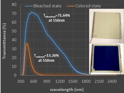
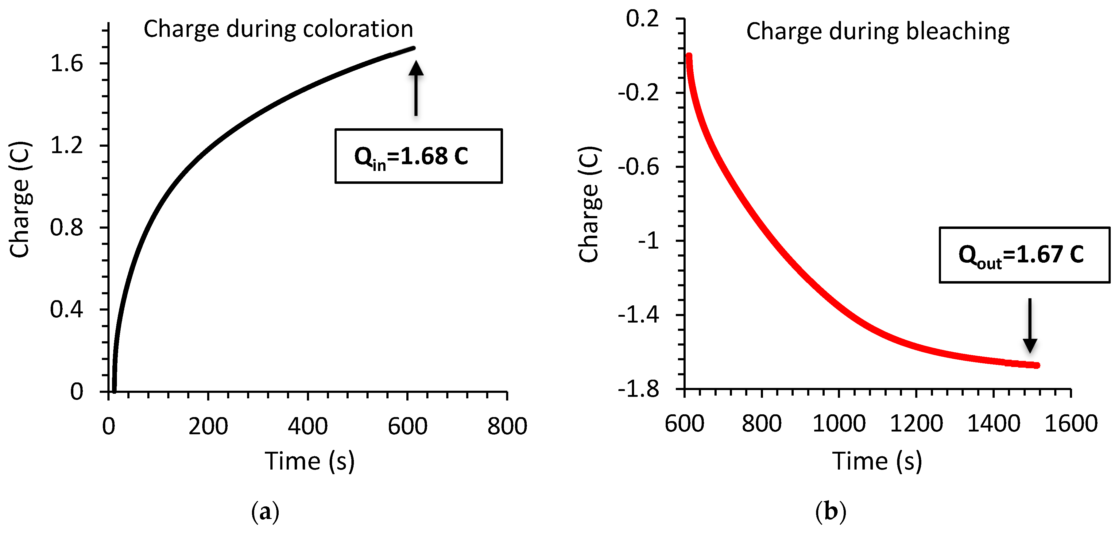
| EC Device | Tb (%) * | Tc (%) * | ΔOD(λ) | qin (C) | A (cm2) | η (cm2/C) |
|---|---|---|---|---|---|---|
| 9 cm × 10 cm | 71.64 | 13.26 | 0.73 | 1.68 | 71.28 | 30.97 |
| EC Device | E (mWh cm−2) | P (mW cm−2) | Ca (mF cm−2) |
|---|---|---|---|
| 9 cm × 10 cm | 1.95 × 10⁻³ | 7.82 × 10⁻³ | 156.2 |
© 2020 by the authors. Licensee MDPI, Basel, Switzerland. This article is an open access article distributed under the terms and conditions of the Creative Commons Attribution (CC BY) license (http://creativecommons.org/licenses/by/4.0/).
Share and Cite
Theodosiou, K.; Giannopoulos, P.; Georgakopoulos, T.; Stathatos, E. Quasi-Solid-State Electrochromic Cells with Energy Storage Properties Made with Inkjet Printing. Materials 2020, 13, 3241. https://0-doi-org.brum.beds.ac.uk/10.3390/ma13143241
Theodosiou K, Giannopoulos P, Georgakopoulos T, Stathatos E. Quasi-Solid-State Electrochromic Cells with Energy Storage Properties Made with Inkjet Printing. Materials. 2020; 13(14):3241. https://0-doi-org.brum.beds.ac.uk/10.3390/ma13143241
Chicago/Turabian StyleTheodosiou, Krystallia, Panagiotis Giannopoulos, Tilemachos Georgakopoulos, and Elias Stathatos. 2020. "Quasi-Solid-State Electrochromic Cells with Energy Storage Properties Made with Inkjet Printing" Materials 13, no. 14: 3241. https://0-doi-org.brum.beds.ac.uk/10.3390/ma13143241