Surface Evaluation of a Multi-Pass Flexible Magnetic Burnishing Brush for Rough and Soft Ground 60/40 Brass

 , ,
, , 
Abstract
:1. Introduction
2. Experimental Section
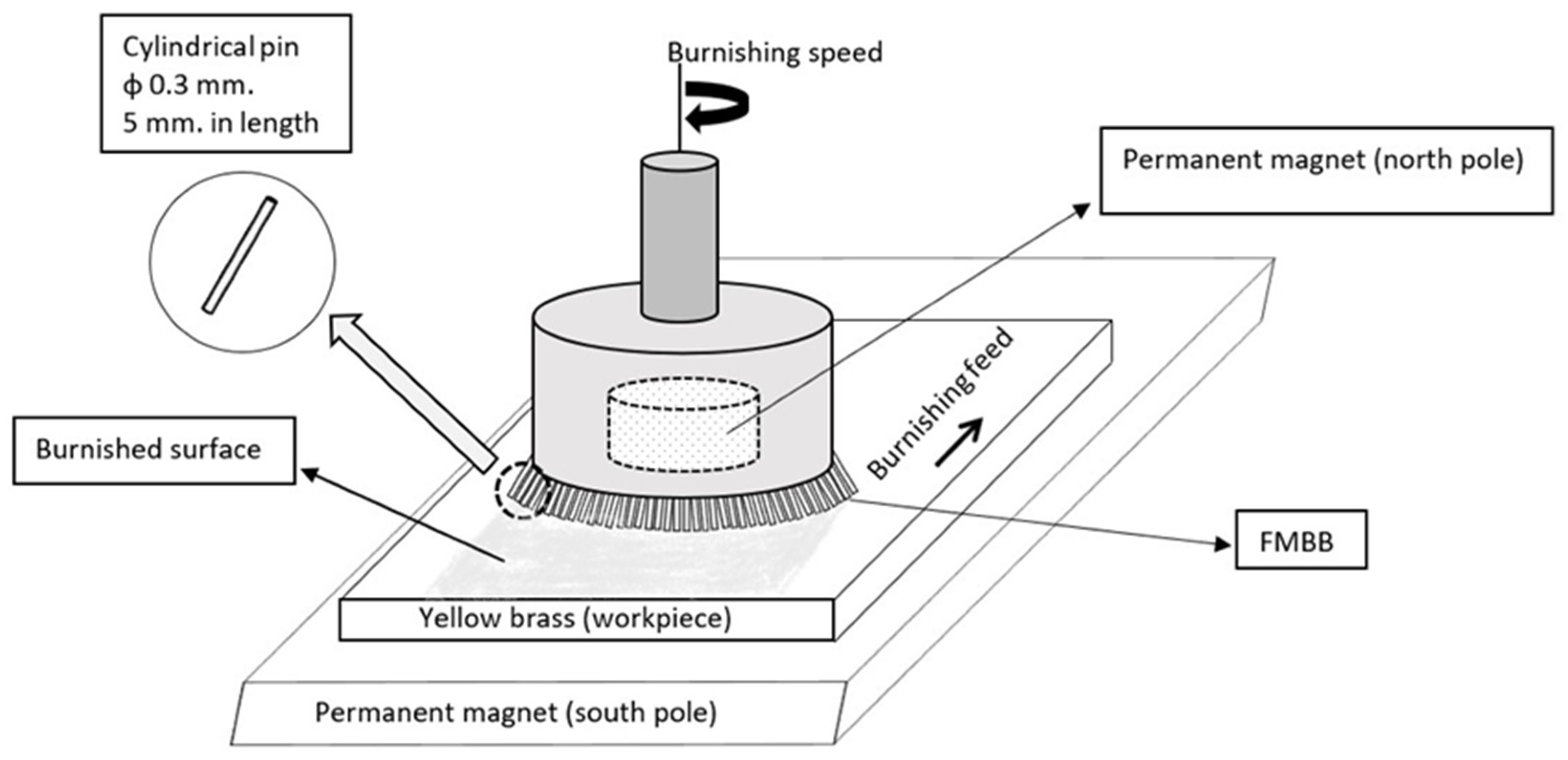
2.1. Material Preparation and Setup
2.2. Multi-Pass Burnishing Processes
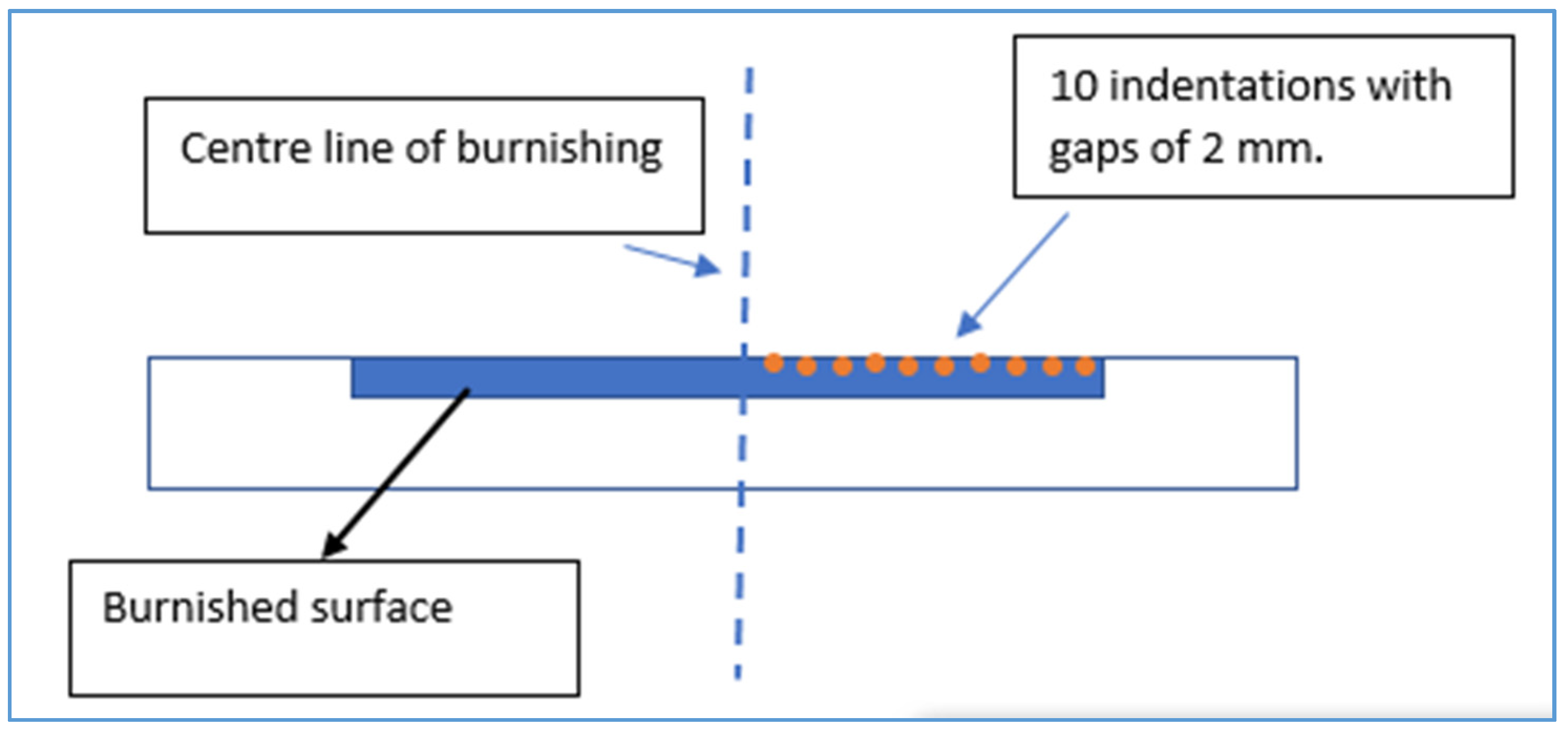
2.3. Experimental Tests
3. Results
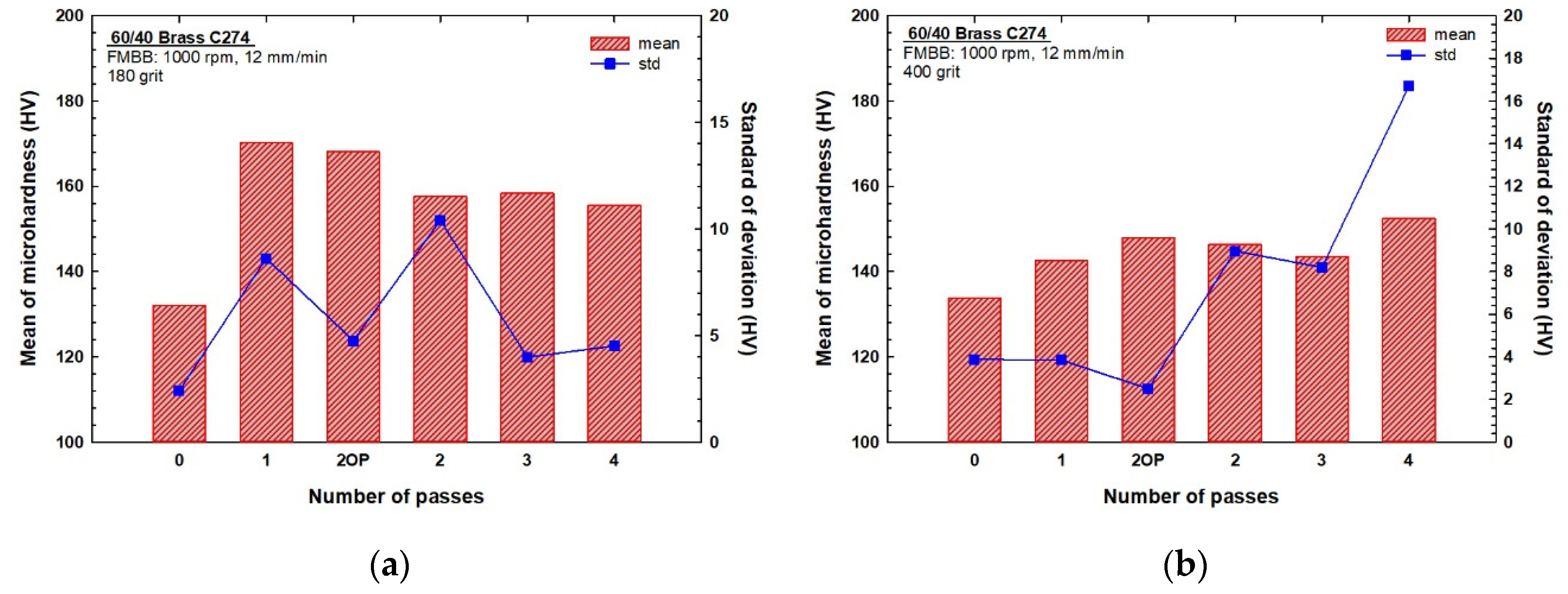
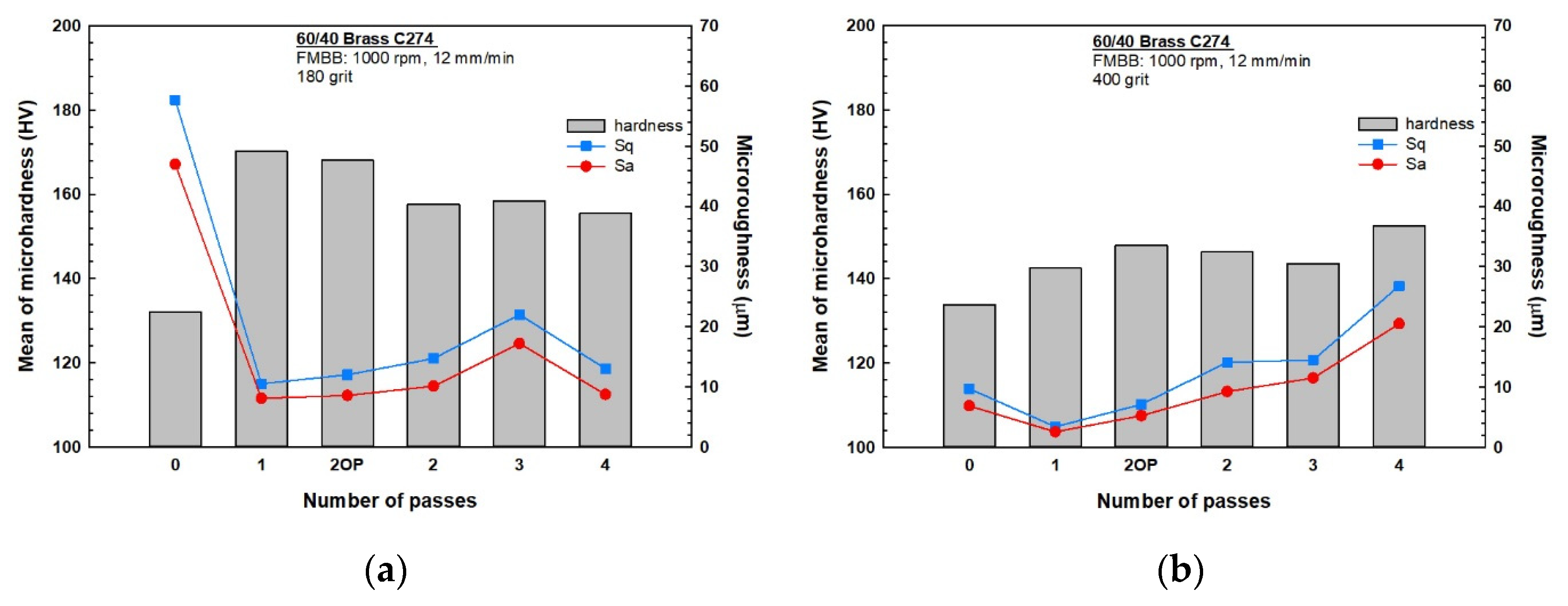
3.1. Microhardness
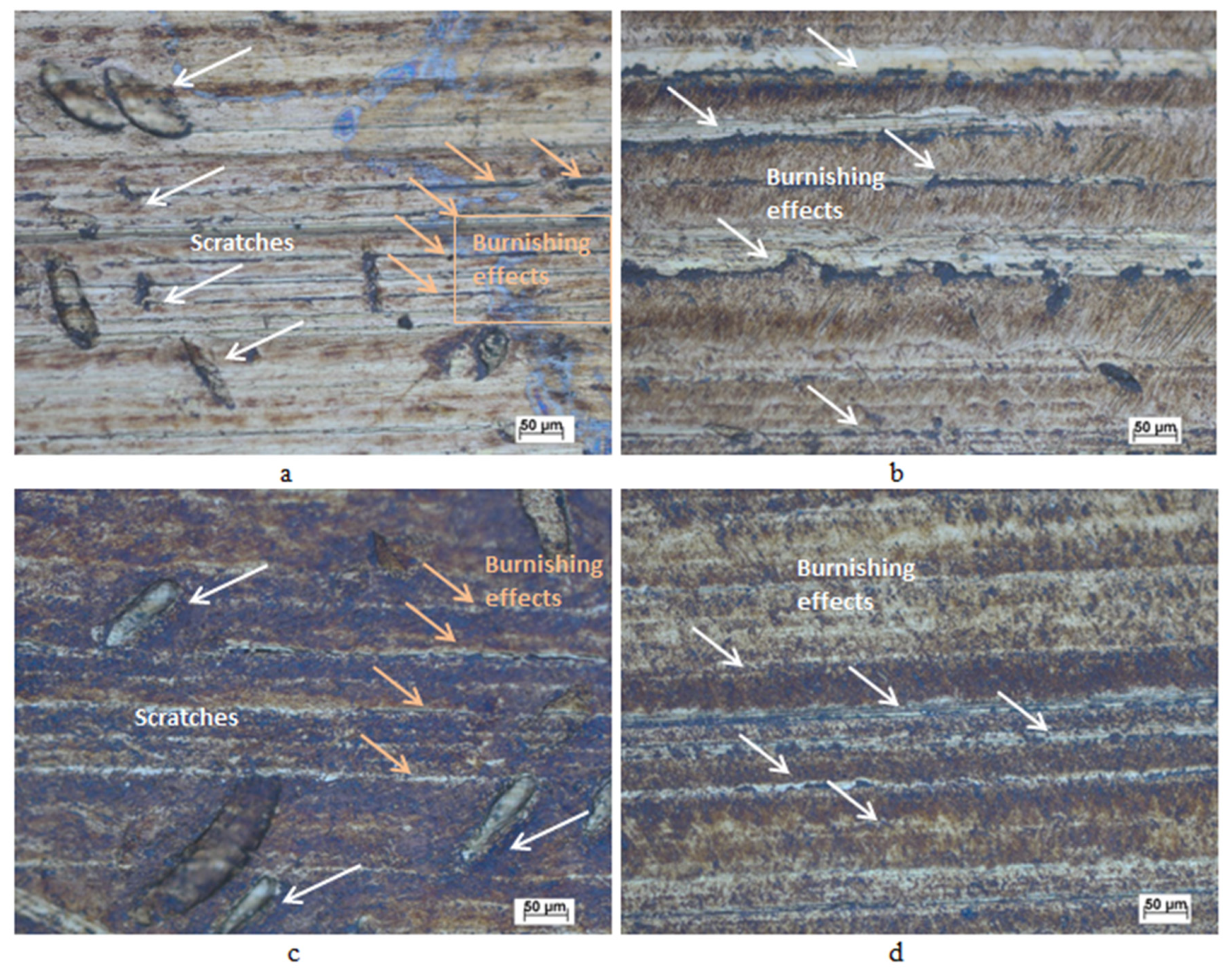
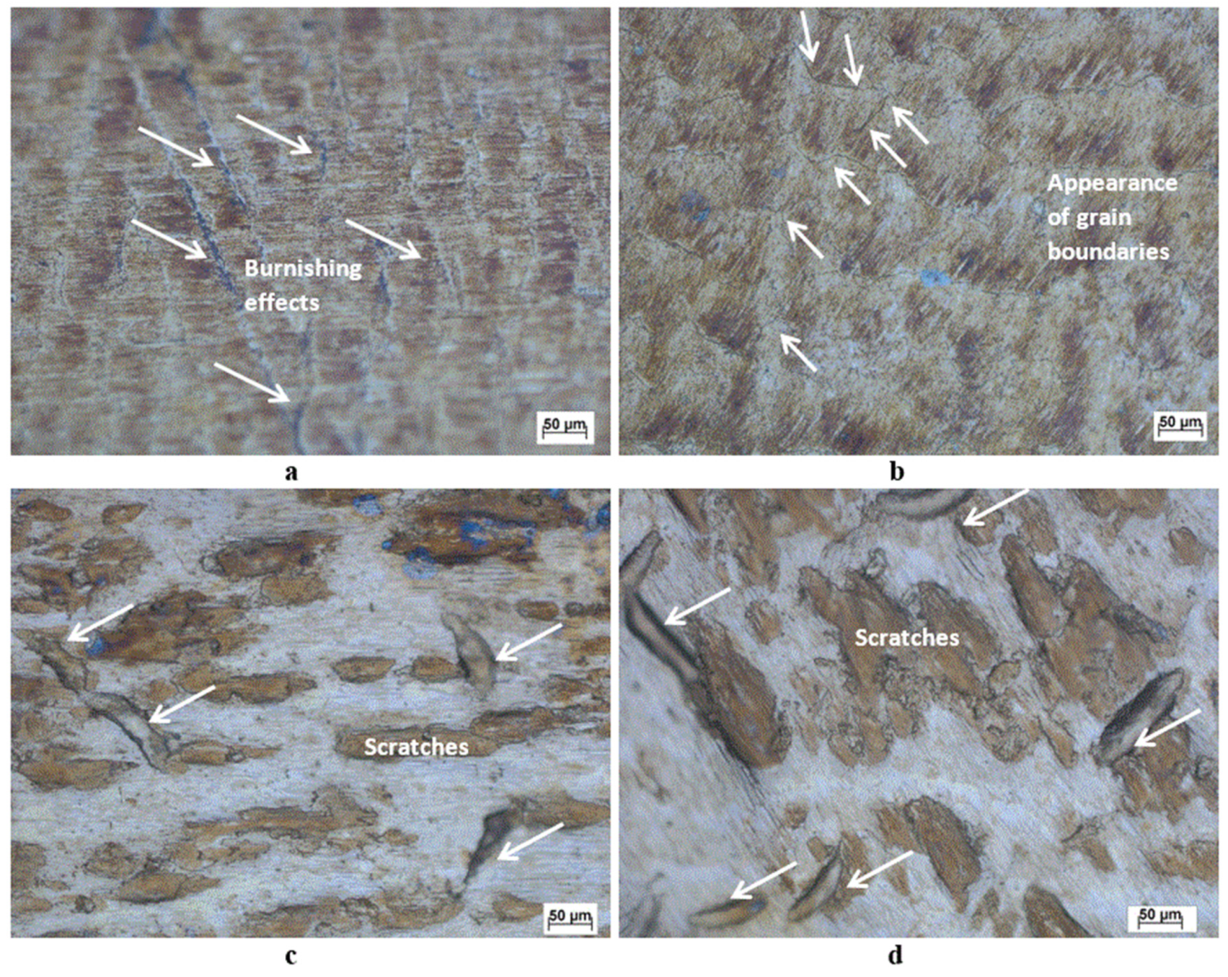
3.2. Microscopic Topography
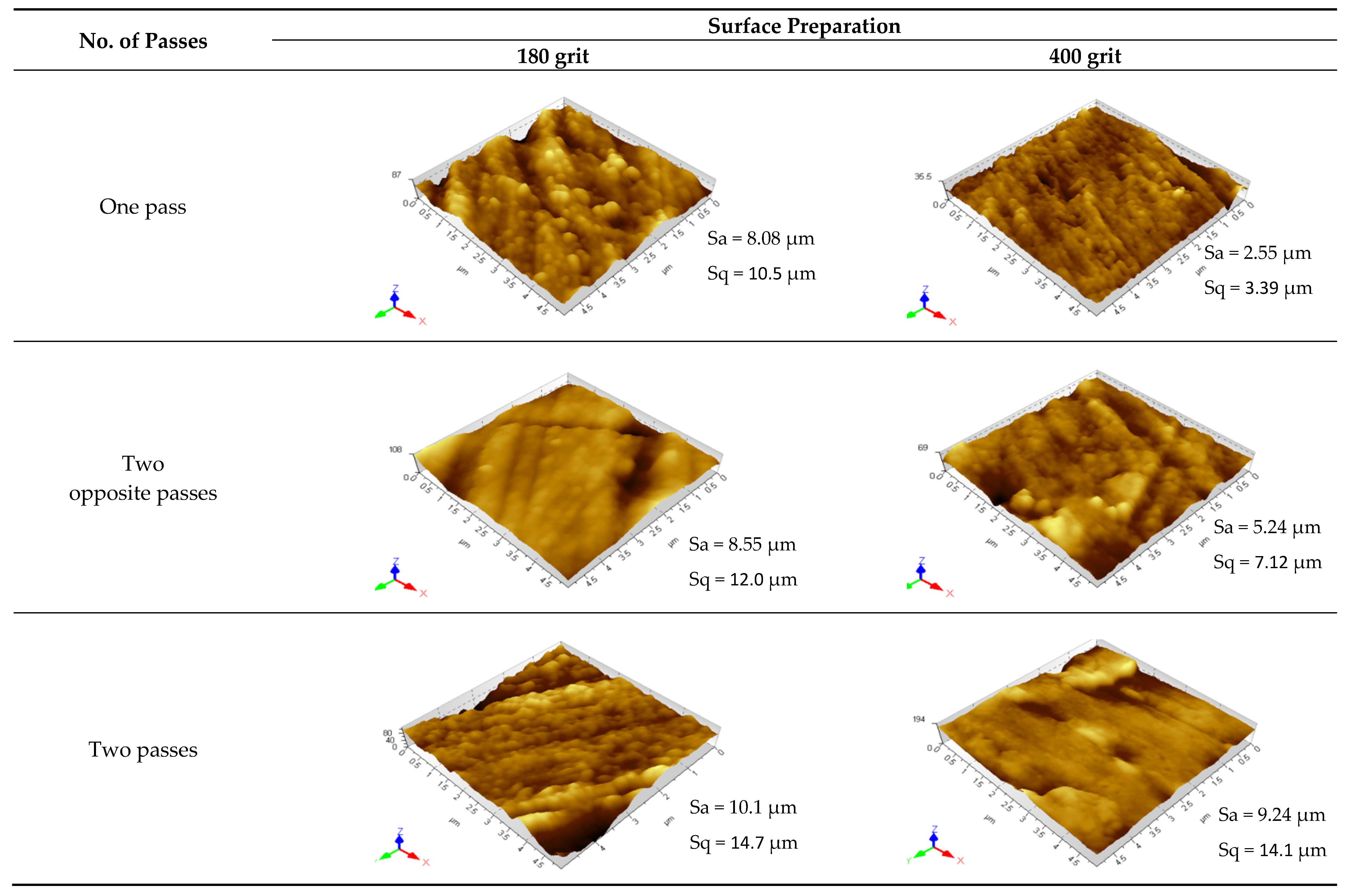
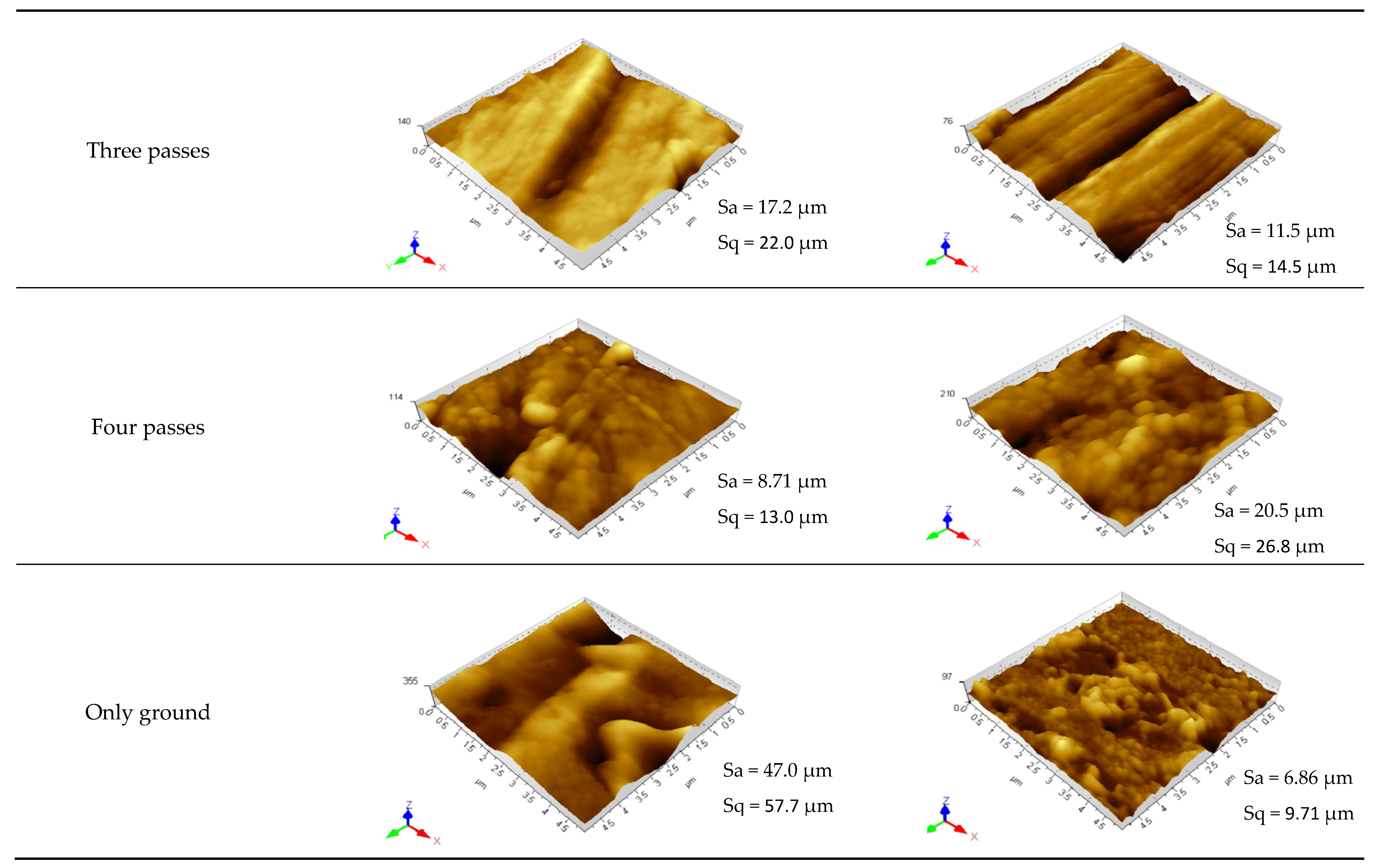
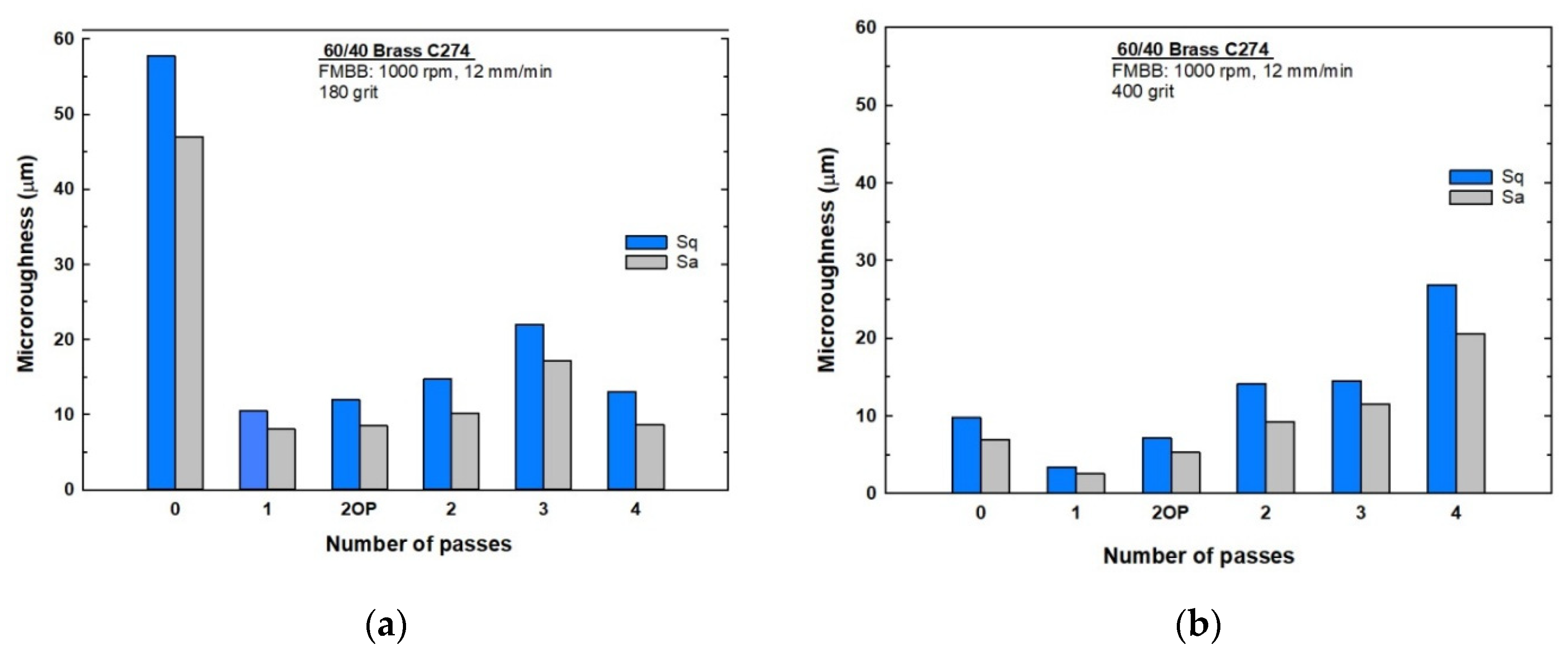
3.3. Microroughness
4. Discussion
4.1. Influence of Initial Surface Condition
4.2. Influence of the Number of Burnishing Passes
4.3. Influence of Strain Reversal
5. Conclusions
- The initial surface roughness plays a major role in the final surface in terms of surface integrity; as the applied force is optimal, larger deformation occurs on a rougher surface.
- Generally, increasing the number of passes increases the surface roughness owing to surface deformation resistance and over-hardening, which in turn changes the process to initiate flaking.
- The rougher-surface brass samples provide better final hardness improvements, and as the number of passes increases, the samples become less hard and rougher but with better uniformity in comparison with the previous pass owing to over-hardening and flaking mechanisms.
- The smoother surface of the brass samples delivers a limited improvement in hardness, because the exerted force is less than the optimum burnishing force.
- As the number of passes increases for smoother-surface samples, the microhardness, surface roughness, and non-uniformity increase owing to over-surface hardening because of repeated burnishing at some sample locations. This leads to surface flaking and an increase in the coefficient of friction.
- Opposite burnishing passes are found to be beneficial to the machined surface owing to the reverse strain mechanism, which has shown better surface roughness, process uniformity, and microhardness improvements than using two same-direction passes.
- Two opposite passes are preferable, rather than one pass wherein the surface roughness and microhardness showed almost no change with high process uniformity.
Author Contributions
Funding
Conflicts of Interest
References
- Nalbant, M.; Gökkaya, H.; Sur, G. Application of Taguchi method in the optimization of cutting parameters for surface roughness in turning. Mater. Des. 2007, 28, 1379–1385. [Google Scholar] [CrossRef]
- Routara, B.C.; Bandyopadhyay, A.; Sahoo, P. Roughness modeling and optimization in CNC end milling using response surface method: Effect of workpiece material variation. Int. J. Adv. Manuf. Technol. 2008, 40, 1166–1180. [Google Scholar] [CrossRef]
- El-Tayeb, N.S.M.; Low, K.O.; Brevern, P.V. Influence of roller burnishing contact width and burnishing orientation on surface quality and tribological behaviour of Aluminium 6061. J. Mater. Process. Technol. 2007, 186, 272–278. [Google Scholar] [CrossRef]
- Verma, J.; Agrawal, P.; Bajpai, L. Turning parameter optimization for surface roughness of ASTM A242 type-1 alloys steel by Taguchi method. Int. J. Adv. Eng. Technol. 2012, 3, 255–261. [Google Scholar]
- Kumara, P.; Purohit, G. Investigations on effect of different ball burnishing conditions on surface roughness using response surface methodology. J. Mod. Manuf. Syst. Technol. 2019, 2, 51–60. [Google Scholar]
- Świrad, S.; Wydrzynski, D.; Nieslony, P.; Krolczyk, G.M. Influence of hydrostatic burnishing strategy on the surface topography of martensitic steel. Measurement 2019, 138, 590–601. [Google Scholar] [CrossRef]
- Teimouri, R.; Amini, S. Analytical modeling of ultrasonic burnishing process: Evaluation of active forces. Measurement 2019, 131, 654–663. [Google Scholar] [CrossRef]
- Hassanifard, S.; Mousavi, H.; Varvani-Farahani, A. The influence of low-plasticity burnishing process on the fatigue life of friction-stir-processed Al 7075-T6 samples. Fatigue Fract. Eng. Mater. Struct. 2018, 42, 764–772. [Google Scholar] [CrossRef]
- Dzierwa, A.; Markopoulos, A. Influence of ball-burnishing process on surface topography parameters and tribological properties of hardened steel. Machines 2019, 7, 11. [Google Scholar] [CrossRef] [Green Version]
- Teimouri, R.; Amini, S.; Bami, A.B. Evaluation of optimized surface properties and residual stress in ultrasonic assisted ball burnishing of AA6061-T6. Measurement 2018, 116, 129–139. [Google Scholar] [CrossRef]
- Rodríguez, A.; López de Lacalle, L.N.; Celaya, A.; Lamikiz, A.; Albizuri, J. Surface improvement of shafts by the deep ball-burnishing technique. Surf. Coat. Technol. 2012, 206, 2817–2824. [Google Scholar] [CrossRef]
- Gharbi, F.; Sghaier, S.; Al-Fadhalah, K.J.; Benameur, T. Effect of ball burnishing process on the surface quality and microstructure properties of AISI 1010 steel plates. J. Mater. Eng. Perform. 2010, 20, 903–910. [Google Scholar] [CrossRef]
- Yin, C.; Wang, R.; Kim, J.; Lee, S.; Mun, S. Ultra-high-speed magnetic abrasive surface micro-machining of AISI 304 cylindrical bar. Metals 2019, 9, 489. [Google Scholar] [CrossRef] [Green Version]
- Niemczewska-Wójcik, M. Multi-sensor measurements of titanium alloy surface texture formed at subsequent operations of precision machining process. Measurement 2017, 96, 8–17. [Google Scholar] [CrossRef]
- Heng, L.; Yin, C.; Han, S.H.; Song, J.H.; Mun, S.D. Development of a new ultra-high-precision magnetic abrasive finishing for wire material using a rotating magnetic field. Materials 2019, 12, 312. [Google Scholar] [CrossRef] [Green Version]
- Kumar, V.; Sharma, R.; Dhakar, K.; Singla, Y.K.; Verma, K. Experimental evaluation of magnetic abrasive finishing process with diamond abrasive. Int. J. Mater. Prod. Technol. 2019, 58, 55–70. [Google Scholar] [CrossRef]
- Peruri, S.R.; Chaganti, P.K. A review of magnetic-assisted machining processes. J. Braz. Soc. Mech. Sci. Eng. 2019, 41, 450. [Google Scholar] [CrossRef]
- Hassan, A.M. The effects of ball- and roller-burnishing on the surface roughness and hardness of some non-ferrous metals. J. Mater. Process. Technol. 1997, 72, 385–391. [Google Scholar] [CrossRef]
- Okada, M.; Shinya, M.; Matsubara, H.; Kozuka, H.; Tachiya, H.; Asakawa, N.; Otsu, M. Development and characterization of diamond tip burnishing with a rotary tool. J. Mater. Process. Technol. 2017, 244, 106–115. [Google Scholar] [CrossRef]
- Alaskari, A.; Albannai, A.; Althaqeb, B.; Liptakova, T. Improving the surface quality of 60/40 brass using flexible magnetic burnishing brush formed with permanent magnets. Manuf. Lett. 2020, 24, 113–122. [Google Scholar] [CrossRef]
- Nguyen, T.-T.; Cao, L.-H.; Nguyen, T.-A.; Dang, X.-P. Multi-response optimization of the roller burnishing process in terms of energy consumption and product quality. J. Clean. Prod. 2020, 245, 119328. [Google Scholar] [CrossRef]
- Lin, Y.C.; Wang, S.W.; Lai, H.-Y. The relationship between surface roughness and burnishing factor in the burnishing process. Int. J. Adv. Manuf. Technol. 2004, 23, 666–671. [Google Scholar] [CrossRef]
- American Society for Testing Materials International. Test Method for Microindentation Hardness of Materials. ASTM Int. 2017. [Google Scholar] [CrossRef]
- Gao, Y.; Li, X.; Yang, Q.; Yao, M. Influence of surface integrity on fatigue strength of 40CrNi2Si2MoVA steel. Mater. Lett. 2007, 61, 466–469. [Google Scholar] [CrossRef]
- Field, M.; Kahles, J.F. The surface integrity of machined and high strength steels. DMIC Rep. 1964, 210, 54–77. [Google Scholar]
- Davim, J.P. Surface Integrity in Machining; Springer: London, UK, 2010. [Google Scholar] [CrossRef]
- Loveless, T.R.; Williams, R.E.; Rajurkar, K.P. A study of the effects of abrasive-flow finishing on various machined surfaces. J. Mater. Process. Technol. 1994, 47, 133–151. [Google Scholar] [CrossRef]
- Ehle, L.; Kämmler, J.; Meyer, D.; Schwedt, A.; Mayer, J. Electron microscopic characterization of mechanically modified surface layers of deep rolled steel. Procedia CIRP 2016, 45, 367–370. [Google Scholar] [CrossRef] [Green Version]
- Belov, V.A. Burnishing surface with ball tools. Mach. Tool 1963, 34, 23–26. [Google Scholar]
- Callister, W.D.J.; Rethwisch, D.G. Materials Science and Engineering: An Introduction, 10th ed.; Wiley: Hoboken, NJ, USA, 2018. [Google Scholar]
- Hassan, A.M.; Maqableh, A.M. The effects of initial burnishing parameters on non-ferrous components. J. Mater. Process. Technol. 2000, 102, 115–121. [Google Scholar] [CrossRef]
- Alekseev, P.G. The wear resistance of burnished fiat surfaces. Mach. Tool 1965, 36, 30–33. [Google Scholar]
- El-Taweel, T.A.; El-Axir, M.H. Analysis and optimization of the ball burnishing process through the Taguchi technique. Int. J. Adv. Manuf. Technol. 2008, 41, 301–310. [Google Scholar] [CrossRef]
- Babu, P.R.; Prasad, T.S.; Raju, A.V.S.; Babu, A.J. The wear resistance of burnished fiat surfaces. J. Sci. Ind. Res. 2009, 68, 29–31. [Google Scholar]
- Loh, N.H.; Tam, S.C. Effects of ball burnishing parameters on surface finish—A literature survey and discussion. Precis. Eng. 1988, 10, 215–220. [Google Scholar] [CrossRef]
- Hassan, A.M.; Al-Jalil, H.F.; Ebied, A.A. Burnishing force and number of ball passes for the optimum surface finish of brass components. J. Mater. Process. Technol. 1998, 83, 176–179. [Google Scholar] [CrossRef]
- Revankar, G.D.; Shetty, R.; Rao, S.S.; Gaitonde, V.N. Analysis of surface roughness and hardness in ball burnishing of titanium alloy. Measurement 2014, 58, 256–268. [Google Scholar] [CrossRef]
- Bauschinger, J. On the change of the position of the elastic limit iron and steel under cyclic variations of stress. Mitt. Mech. Tech. Lab. 1886, 13. [Google Scholar]
- Seeger, A.; Diehl, J.; Mader, S.; Rebstock, H. Work-hardening and work-softening of face-centred cubic metal crystals. Philos. Mag. 1957, 2, 323–350. [Google Scholar] [CrossRef]
- Mott, N.F. CXVII. A theory of work-hardening of metal crystals. Lond. Edinb. Dublin Philos. Mag. J. Sci. 1952, 43, 1151–1178. [Google Scholar] [CrossRef]
- Yapici, G.G.; Beyerlein, I.J.; Karaman, I.; Tomé, C.N. Tension–compression asymmetry in severely deformed pure copper. Acta Mater. 2007, 55, 4603–4613. [Google Scholar] [CrossRef]


| Element | C274 (brass) | SS303 (pins) |
|---|---|---|
| Cu | 60.70 | 0.55 |
| Zn | 39.20 | – |
| Fe | – | 70.81 |
| Cr | – | 18.15 |
| Ni | 0.13 | 8.14 |
| Mn | – | 1.60 |
| Mo | – | 0.28 |
| Initial Grinding Grit | Sample Name | Process | |||
|---|---|---|---|---|---|
| 180 | One Pass | First Pass | |||
| Two opposite passes | First pass | Second pass opposite direction | |||
| Two passes | First pass | Second pass | |||
| Three passes | First pass | Second pass | Third pass | ||
| Four passes | First pass | Second pass | Third pass | Fourth pass | |
| 400 | One pass | First pass | |||
| Two opposite passes | First pass | Second pass opposite direction | |||
| Two passes | First pass | Second pass | |||
| Three passes | First pass | Second pass | Third pass | ||
| Four passes | First pass | Second pass | Third pass | Fourth pass | |
© 2020 by the authors. Licensee MDPI, Basel, Switzerland. This article is an open access article distributed under the terms and conditions of the Creative Commons Attribution (CC BY) license (http://creativecommons.org/licenses/by/4.0/).
Share and Cite
Alaskari, A.M.; Albannai, A.I.; Alawadhi, M.Y.; Aloraier, A.S.; Liptakova, T.; Alazemi, A.A. Surface Evaluation of a Multi-Pass Flexible Magnetic Burnishing Brush for Rough and Soft Ground 60/40 Brass. Materials 2020, 13, 4465. https://0-doi-org.brum.beds.ac.uk/10.3390/ma13194465
Alaskari AM, Albannai AI, Alawadhi MY, Aloraier AS, Liptakova T, Alazemi AA. Surface Evaluation of a Multi-Pass Flexible Magnetic Burnishing Brush for Rough and Soft Ground 60/40 Brass. Materials. 2020; 13(19):4465. https://0-doi-org.brum.beds.ac.uk/10.3390/ma13194465
Chicago/Turabian StyleAlaskari, Ayman M., Abdulaziz I. Albannai, Meshal Y. Alawadhi, Abdulkareem S. Aloraier, Tatiana Liptakova, and Abdullah A. Alazemi. 2020. "Surface Evaluation of a Multi-Pass Flexible Magnetic Burnishing Brush for Rough and Soft Ground 60/40 Brass" Materials 13, no. 19: 4465. https://0-doi-org.brum.beds.ac.uk/10.3390/ma13194465