
Manganese–Cobalt Based Spinel Coatings Processed by Electrophoretic Deposition Method: The Influence of Sintering on Degradation Issues of Solid Oxide Cell Oxygen Electrodes at 750 °C

 , , , , and
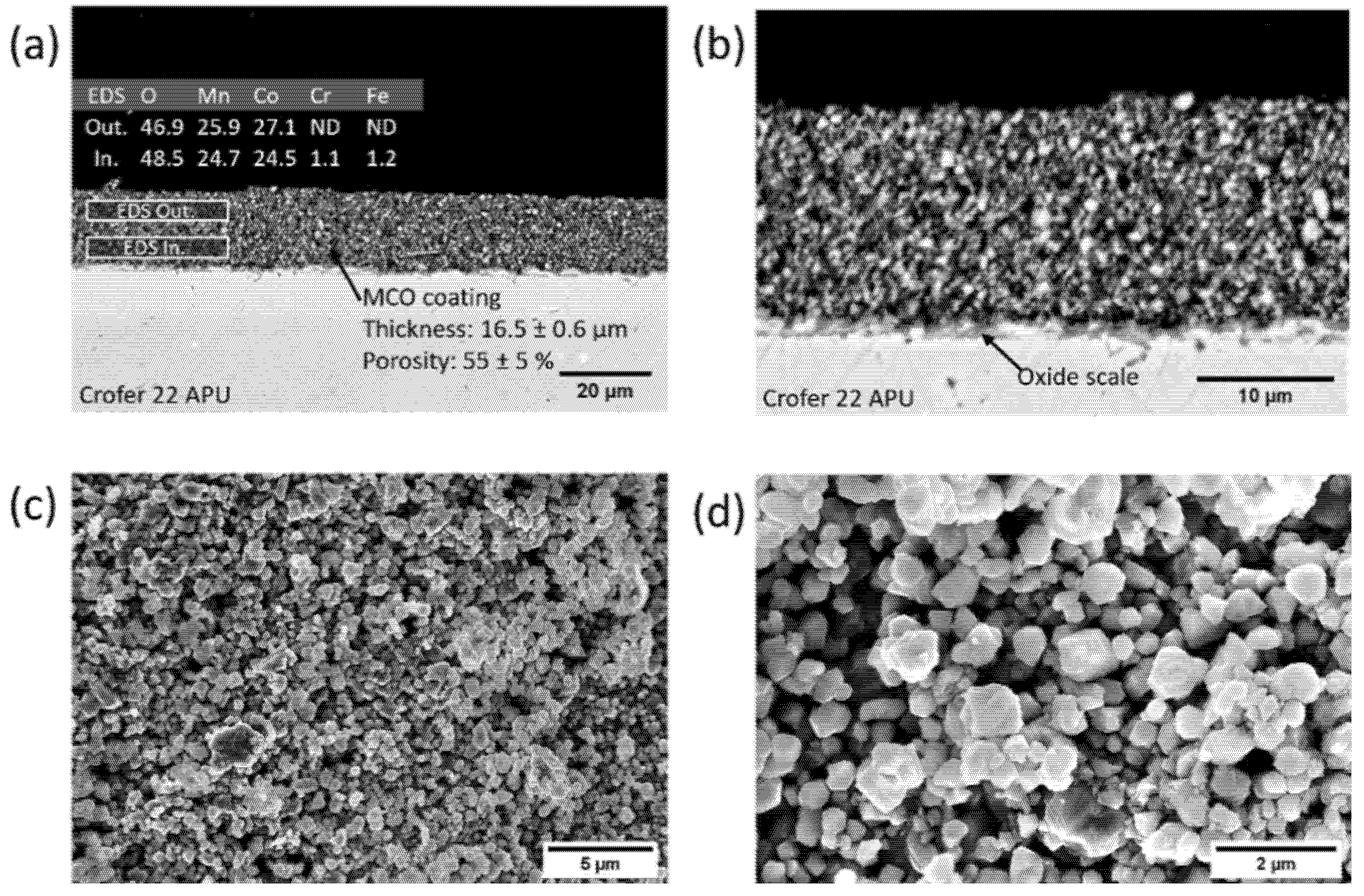
Abstract
:1. Introduction
2. Materials and Methods
2.1. Coating Deposition and Sintering
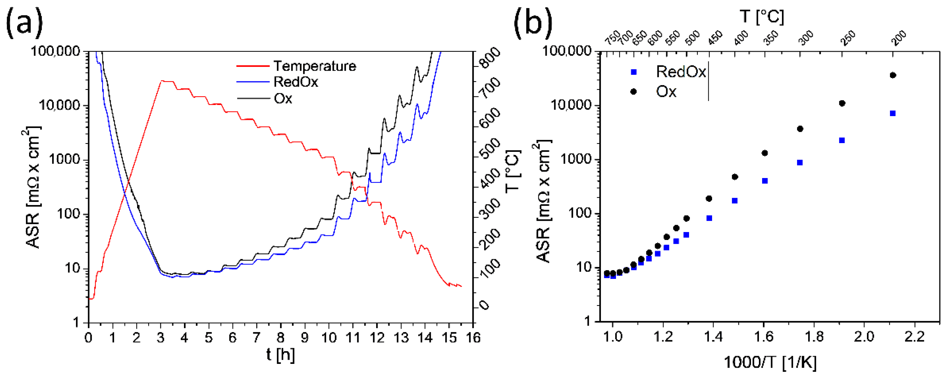
2.2. Area-Specific Resistance Measurement Test
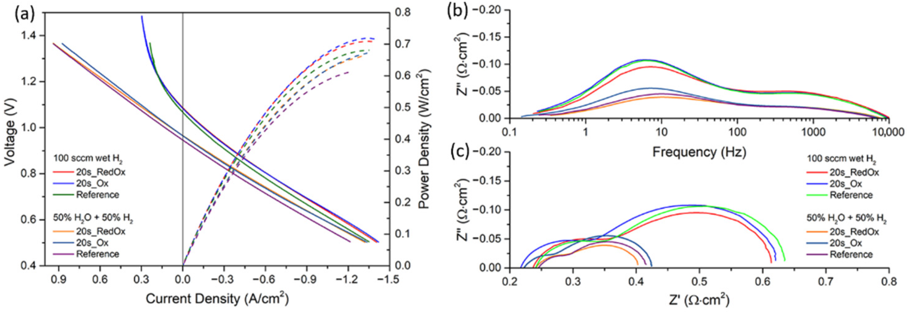
2.3. Interconnect Aging, Cr Evaporation Exposure and Fuel Cell Test
2.4. Morphological and Compositional Characterization
3. Results and Discussion
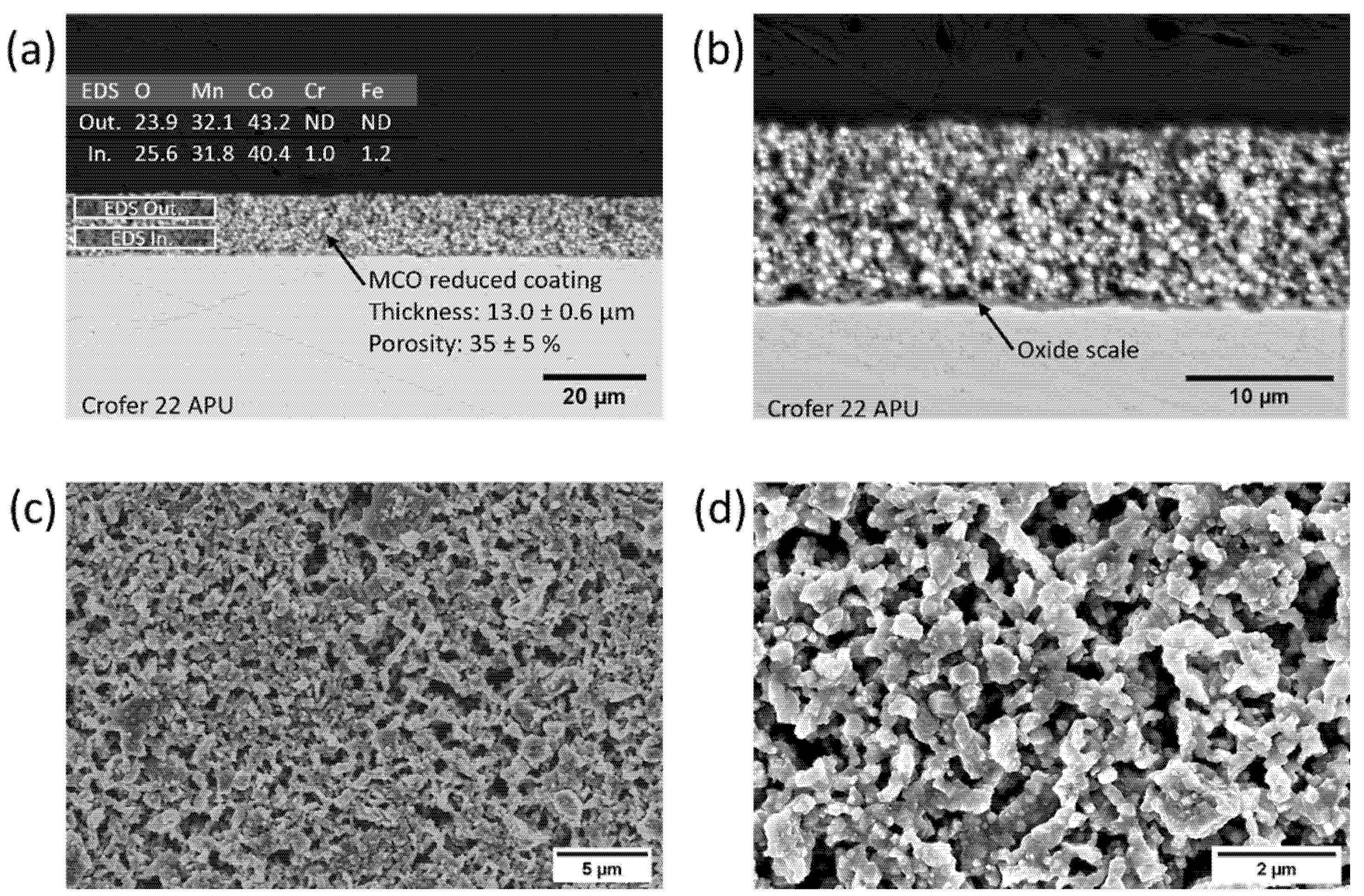
3.1. Characterization of As-Prepared Samples
3.2. Aging Exposure at 750 °C and Cell Test Results
3.3. Post-Mortem Characterization
4. Conclusions
Author Contributions
Funding
Institutional Review Board Statement
Informed Consent Statement
Data Availability Statement
Conflicts of Interest
References
- Stanislowski, M.; Wessel, E.; Hilpert, K.; Markus, T.; Singheiser, L. Chromium Vaporization from High-Temperature Alloys. J. Electrochem. Soc. 2007, 154, A295–A306. [Google Scholar] [CrossRef]
- Shaigan, N.; Qu, W.; Ivey, D.G.; Chen, W. A review of recent progress in coatings, surface modifications and alloy developments for solid oxide fuel cell ferritic stainless steel interconnects. J. Power Sources 2010, 195, 1529–1542. [Google Scholar] [CrossRef]
- Mah, J.C.; Muchtar, A.; Somalu, M.R.; Ghazali, M.J. Metallic interconnects for solid oxide fuel cell: A review on protective coating and deposition techniques. Int. J. Hydrogen Energy 2017, 42, 9219–9229. [Google Scholar] [CrossRef]
- Tan, K.; Rahman, H.; Taib, H. Coating layer and influence of transition metal for ferritic stainless steel interconnector solid oxide fuel cell: A review. Int. J. Hydrogen Energy 2019, 44, 30591–30605. [Google Scholar] [CrossRef]
- Masi, A.; Bellusci, M.; McPhail, S.J.; Padella, F.; Reale, P.; Hong, J.-E.; Steinberger-Wilckens, R.; Carlini, M. The effect of chemical composition on high temperature behaviour of Fe and Cu doped Mn-Co spinels. Ceram. Int. 2017, 43, 2829–2835. [Google Scholar] [CrossRef]
- Talic, B.; Molin, S.; Wiik, K.; Hendriksen, P.V.; Lein, H.L. Comparison of iron and copper doped manganese cobalt spinel oxides as protective coatings for solid oxide fuel cell interconnects. J. Power Sources 2017, 372, 145–156. [Google Scholar] [CrossRef] [Green Version]
- Molin, S.; Sabato, A.G.; Javed, H.; Cempura, G.; Boccaccini, A.; Smeacetto, F. Co-deposition of CuO and Mn1.5Co1.5O4 powders on Crofer22APU by electrophoretic method: Structural, compositional modifications and corrosion properties. Mater. Lett. 2018, 218, 329–333. [Google Scholar] [CrossRef] [Green Version]
- Zhu, J.; Lewis, M.; Du, S.W.; Li, Y. CeO2-doped (Co,Mn)3O4 coatings for protecting solid oxide fuel cell interconnect alloys. Thin Solid Films 2015, 596, 179–184. [Google Scholar] [CrossRef] [Green Version]
- Brylewski, T.; Molin, S.; Marczyński, M.; Mazur, Ł.; Domaradzki, K.; Kryshtal, O.; Gil, A. Influence of Gd deposition on the oxidation behavior and electrical properties of a layered system consisting of Crofer 22 APU and MnCo2O4 spinel. Int. J. Hydrogen Energy 2021, 46, 6775–6791. [Google Scholar] [CrossRef]
- Mosavi, A.; Ebrahimifar, H. Investigation of oxidation and electrical behavior of AISI 430 steel coated with Mn–Co–CeO2 composite. Int. J. Hydrogen Energy 2020, 45, 3145–3162. [Google Scholar] [CrossRef]
- Stanislowski, M.; Froitzheim, J.; Niewolak, L.; Quadakkers, W.J.; Hilpert, K.; Markus, T.; Singheiser, L.; Stanislowski, M.; Froitzheim, J.; Niewolak, L.; et al. Reduction of chromium vaporization from SOFC interconnectors by highly effective coatings. J. Power Sources 2007, 164, 578–589. [Google Scholar] [CrossRef]
- Molin, S.; Sabato, A.G.; Bindi, M.; Leone, P.; Cempura, G.; Salvo, M.; Polo, S.C.; Boccaccini, A.; Smeacetto, F. Microstructural and electrical characterization of Mn-Co spinel protective coatings for solid oxide cell interconnects. J. Eur. Ceram. Soc. 2017, 37, 4781–4791. [Google Scholar] [CrossRef] [Green Version]
- Bateni, M.R.; Wei, P.; Deng, X.; Petric, A. Spinel coatings for UNS 430 stainless steel interconnects. Surf. Coat. Technol. 2007, 201, 4677–4684. [Google Scholar] [CrossRef]
- Han, S.J.; Pala, Z.; Sampath, S. Plasma sprayed manganese–cobalt spinel coatings: Process sensitivity on phase, electrical and protective performance. J. Power Sources 2016, 304, 234–243. [Google Scholar] [CrossRef] [Green Version]
- Lee, S.-I.; Hong, J.; Kim, H.; Son, J.-W.; Lee, J.-H.; Kim, B.-K.; Lee, H.-W.; Yoon, K.J. Highly Dense Mn-Co Spinel Coating for Protection of Metallic Interconnect of Solid Oxide Fuel Cells. J. Electrochem. Soc. 2014, 161, F1389–F1394. [Google Scholar] [CrossRef] [Green Version]
- Kruk, A.; Stygar, M.; Brylewski, T. Mn–Co spinel protective–conductive coating on AL453 ferritic stainless steel for IT-SOFC interconnect applications. J. Solid State Electrochem. 2012, 17, 993–1003. [Google Scholar] [CrossRef] [Green Version]
- Xiao, J.; Zhang, W.; Xiong, C.; Chi, B.; Pu, J.; Jian, L. Oxidation behavior of Cu-doped MnCo2O4 spinel coating on ferritic stainless steels for solid oxide fuel cell interconnects. Int. J. Hydrogen Energy 2016, 41, 9611–9618. [Google Scholar] [CrossRef] [Green Version]
- Shen, Z.; Rong, J.; Yu, X. Mn Co3O4 spinel coatings: Controlled synthesis and high temperature oxidation resistance behavior. Ceram. Int. 2020, 46, 5821–5827. [Google Scholar] [CrossRef]
- Hu, S.; Li, W.; Finklea, H.; Liu, X. A review of electrophoretic deposition of metal oxides and its application in solid oxide fuel cells. Adv. Colloid Interface Sci. 2020, 276, 102102. [Google Scholar] [CrossRef] [PubMed]
- Zanchi, E.; Sabato, A.; Molin, S.; Cempura, G.; Boccaccini, A.; Smeacetto, F. Recent advances on spinel-based protective coatings for solid oxide cell metallic interconnects produced by electrophoretic deposition. Mater. Lett. 2021, 286, 129229. [Google Scholar] [CrossRef]
- Abdoli, H.; Molin, S.; Farnoush, H. Effect of interconnect coating procedure on solid oxide fuel cell performance. Mater. Lett. 2020, 259, 126898. [Google Scholar] [CrossRef]
- Kalinina, E.G.; Pikalova, E.Y. New trends in the development of electrophoretic deposition method in the solid oxide fuel cell technology: Theoretical approaches, experimental solutions and development prospects. Russ. Chem. Rev. 2019, 88, 1179–1219. [Google Scholar] [CrossRef]
- Besra, L.; Liu, M. A review on fundamentals and applications of electrophoretic deposition (EPD). Prog. Mater. Sci. 2007, 52, 1–61. [Google Scholar] [CrossRef]
- Talic, B.; Wulff, A.; Molin, S.; Andersen, K.; Zielke, P.; Frandsen, H. Investigation of electrophoretic deposition as a method for coating complex shaped steel parts in solid oxide cell stacks. Surf. Coat. Technol. 2019, 380, 125093. [Google Scholar] [CrossRef]
- Zanchi, E.; Talic, B.; Sabato, A.G.; Molin, S.; Boccaccini, A.; Smeacetto, F. Electrophoretic co-deposition of Fe2O3 and Mn1,5Co1,5O4: Processing and oxidation performance of Fe-doped Mn-Co coatings for solid oxide cell interconnects. J. Eur. Ceram. Soc. 2019, 39, 3768–3777. [Google Scholar] [CrossRef]
- Zanchi, E.; Molin, S.; Sabato, A.G.; Talic, B.; Cempura, G.; Boccaccini, A.; Smeacetto, F. Iron doped manganese cobaltite spinel coatings produced by electrophoretic co-deposition on interconnects for solid oxide cells: Microstructural and electrical characterization. J. Power Sources 2020, 455, 227910. [Google Scholar] [CrossRef]
- Sabato, A.G.; Molin, S.; Javed, H.; Zanchi, E.; Boccaccini, A.R.; Smeacetto, F. In-situ Cu-doped MnCo-spinel coatings for solid oxide cell interconnects processed by electrophoretic deposition. Ceram. Int. 2019, 45, 19148–19157. [Google Scholar] [CrossRef]
- Sabato, A.; Zanchi, E.; Molin, S.; Cempura, G.; Javed, H.; Herbrig, K.; Walter, C.; Boccaccini, A.; Smeacetto, F. Mn-Co spinel coatings on Crofer 22 APU by electrophoretic deposition: Up scaling, performance in SOFC stack at 850 °C and compositional modifications. J. Eur. Ceram. Soc. 2021, 41, 4496–4504. [Google Scholar] [CrossRef]
- Bobruk, M.; Molin, S.; Chen, M.; Brylewski, T.; Hendriksen, P.V. Sintering of MnCo2O4 coatings prepared by electrophoretic deposition. Mater. Lett. 2018, 213, 394–398. [Google Scholar] [CrossRef] [Green Version]
- Talic, B.; Falk-Windisch, H.; Venkatachalam, V.; Hendriksen, P.V.; Wiik, K.; Lein, H.L. Effect of coating density on oxidation resistance and Cr vaporization from solid oxide fuel cell interconnects. J. Power Sources 2017, 354, 57–67. [Google Scholar] [CrossRef] [Green Version]
- Falk-Windisch, H.; Svensson, J.E.; Froitzheim, J. The effect of temperature on chromium vaporization and oxide scale growth on interconnect steels for Solid Oxide Fuel Cells. J. Power Sources 2015, 287, 25–35. [Google Scholar] [CrossRef] [Green Version]
- Smeacetto, F.; De Miranda, A.; Polo, S.C.; Molin, S.; Boccaccini, D.; Salvo, M.; Boccaccini, A.R. Electrophoretic deposition of Mn1.5Co1.5O4 on metallic interconnect and interaction with glass-ceramic sealant for solid oxide fuel cells application. J. Power Sources 2015, 280, 379–386. [Google Scholar] [CrossRef]
- Schneider, C.A.; Rasband, W.S.; Eliceiri, K.W. NIH Image to ImageJ: 25 years of image analysis. Nat. Methods 2012, 9, 671–675. [Google Scholar] [CrossRef]
- Gambino, L.V.; Magdefrau, N.J.; Aindow, M. Microstructural effects of the reduction step in reactive consolidation of manganese cobaltite coatings on Crofer 22 APU. Mater. High Temp. 2015, 32, 142–147. [Google Scholar] [CrossRef]


Publisher’s Note: MDPI stays neutral with regard to jurisdictional claims in published maps and institutional affiliations. |
© 2021 by the authors. Licensee MDPI, Basel, Switzerland. This article is an open access article distributed under the terms and conditions of the Creative Commons Attribution (CC BY) license (https://creativecommons.org/licenses/by/4.0/).
Share and Cite
Zanchi, E.; Ignaczak, J.; Kamecki, B.; Jasiński, P.; Molin, S.; Boccaccini, A.R.; Smeacetto, F. Manganese–Cobalt Based Spinel Coatings Processed by Electrophoretic Deposition Method: The Influence of Sintering on Degradation Issues of Solid Oxide Cell Oxygen Electrodes at 750 °C. Materials 2021, 14, 3836. https://0-doi-org.brum.beds.ac.uk/10.3390/ma14143836
Zanchi E, Ignaczak J, Kamecki B, Jasiński P, Molin S, Boccaccini AR, Smeacetto F. Manganese–Cobalt Based Spinel Coatings Processed by Electrophoretic Deposition Method: The Influence of Sintering on Degradation Issues of Solid Oxide Cell Oxygen Electrodes at 750 °C. Materials. 2021; 14(14):3836. https://0-doi-org.brum.beds.ac.uk/10.3390/ma14143836
Chicago/Turabian StyleZanchi, Elisa, Justyna Ignaczak, Bartosz Kamecki, Piotr Jasiński, Sebastian Molin, Aldo R. Boccaccini, and Federico Smeacetto. 2021. "Manganese–Cobalt Based Spinel Coatings Processed by Electrophoretic Deposition Method: The Influence of Sintering on Degradation Issues of Solid Oxide Cell Oxygen Electrodes at 750 °C" Materials 14, no. 14: 3836. https://0-doi-org.brum.beds.ac.uk/10.3390/ma14143836