
The Influence of Temperature in the Al 2024-T3 Aluminum Plates Subjected to Impact: Experimental and Numerical Approaches

 , ,
, ,  ,
,
Abstract
:1. Introduction
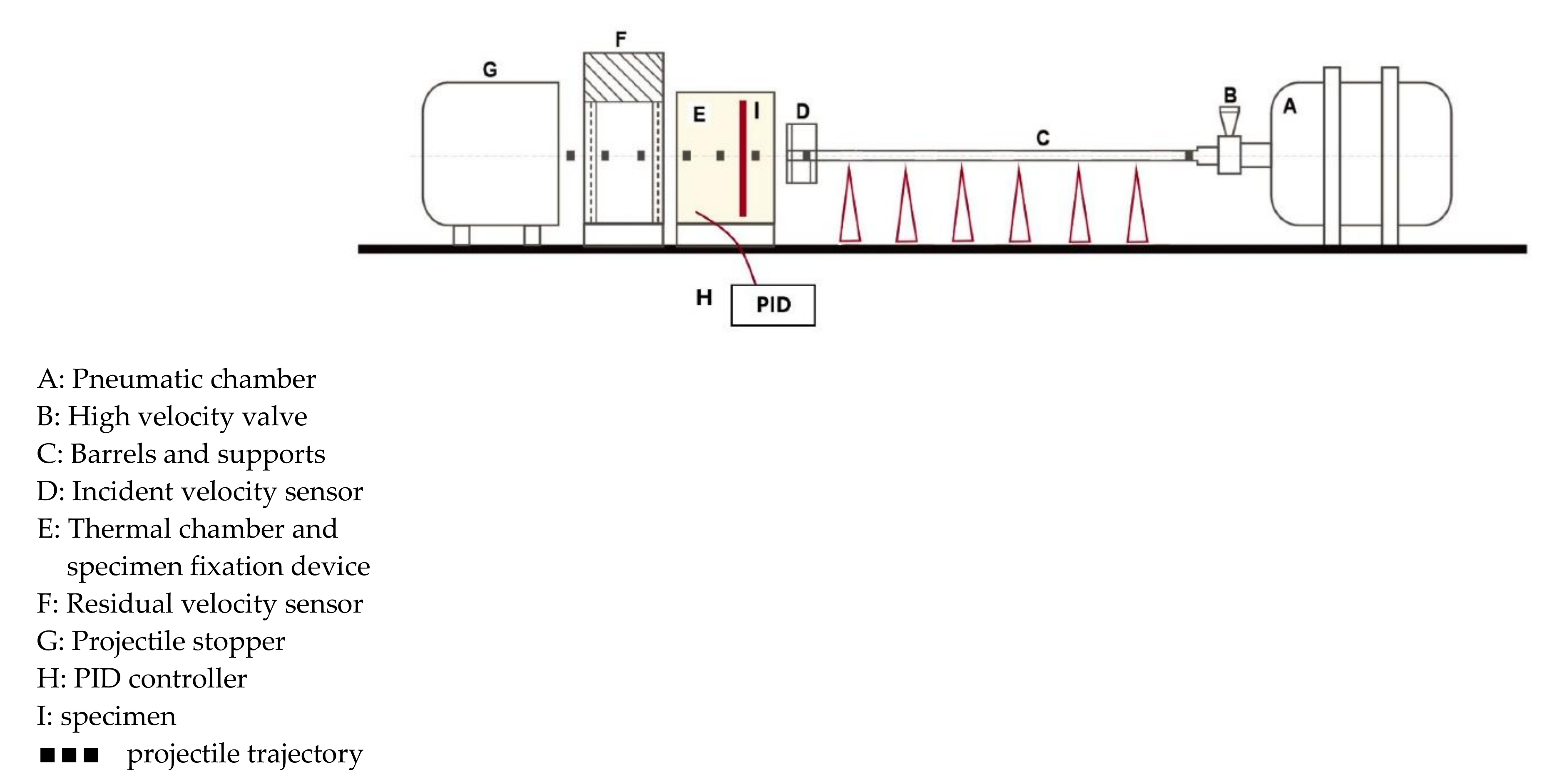
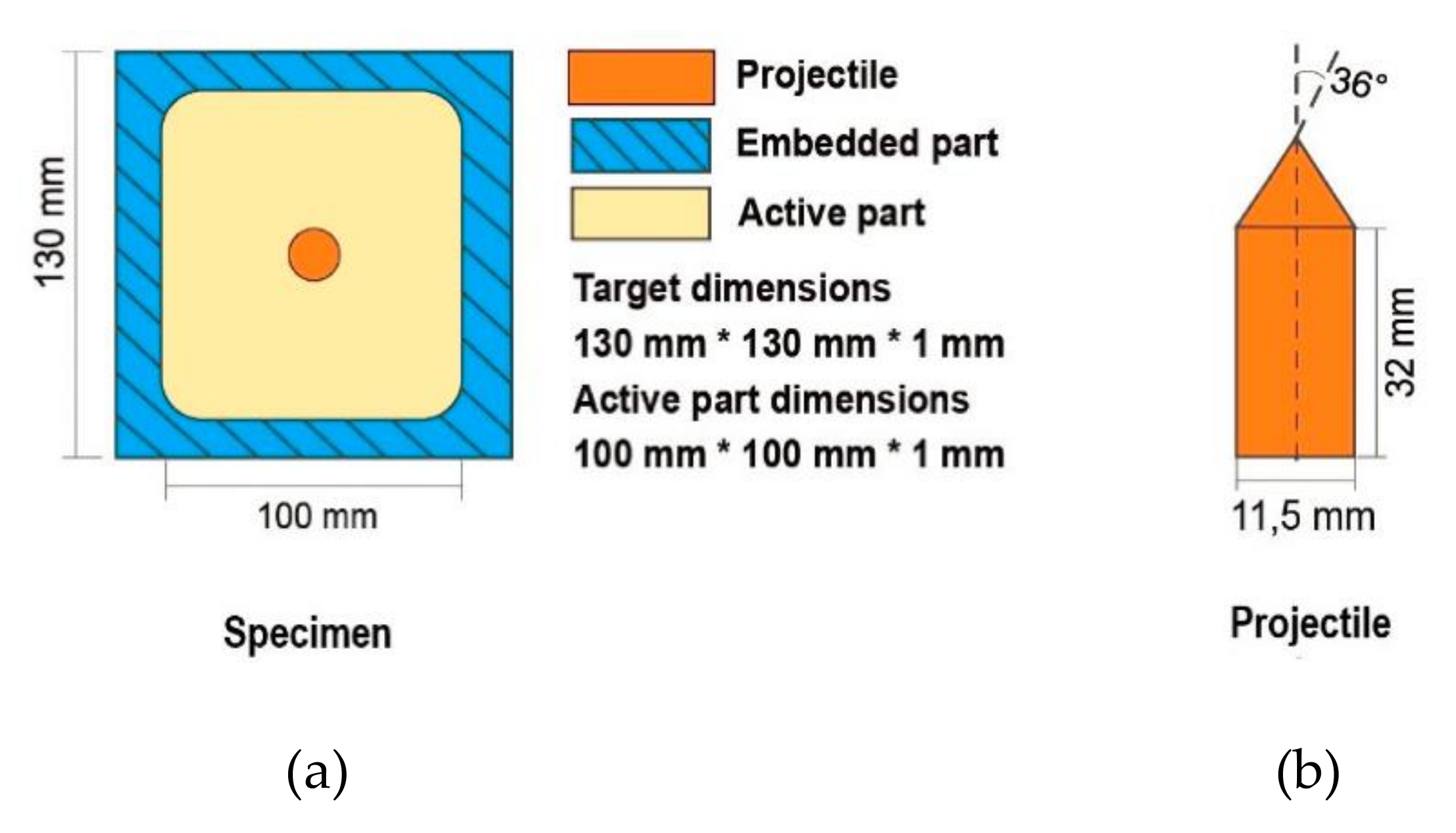
2. Experimental Approach
3. Numerical Modelling
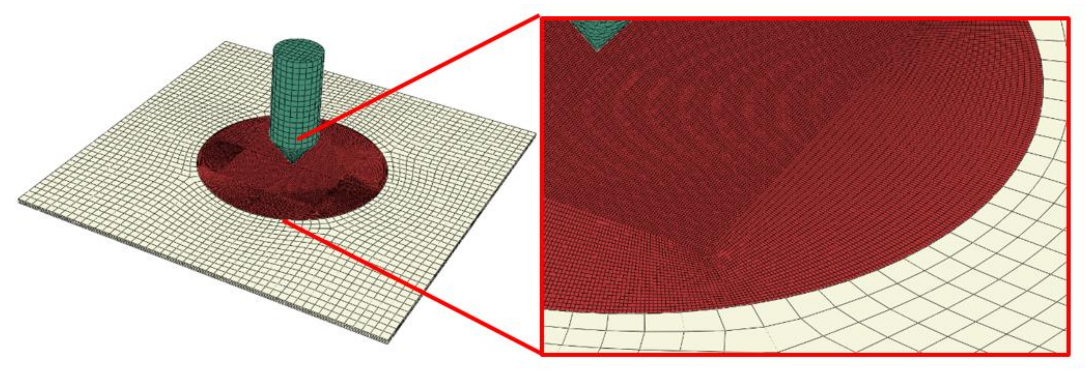
- specimen: fine mesh in the middle with 226805 nodes, and 180096 elements C3D8R (four elements along the thickness, 0.2 mm × 0.2 mm × 0.3 mm); the remaining part has 10,540 nodes, and 7888 elements C3D8I (4 elements along the thickness, 2 mm × 2 mm × 0.3 mm; both parts of the specimen were tied in the analysis, the refined mesh part has a form of a circle of 6 cm in diameter in the region of contact between the two acting bodies;
- projectile: 9302 nodes including cylinder 960 C3D8R elements and cone 5516 C3D10M (tetra) elements (average size 1.5 mm); both parts of the projectile were tied in the analysis.
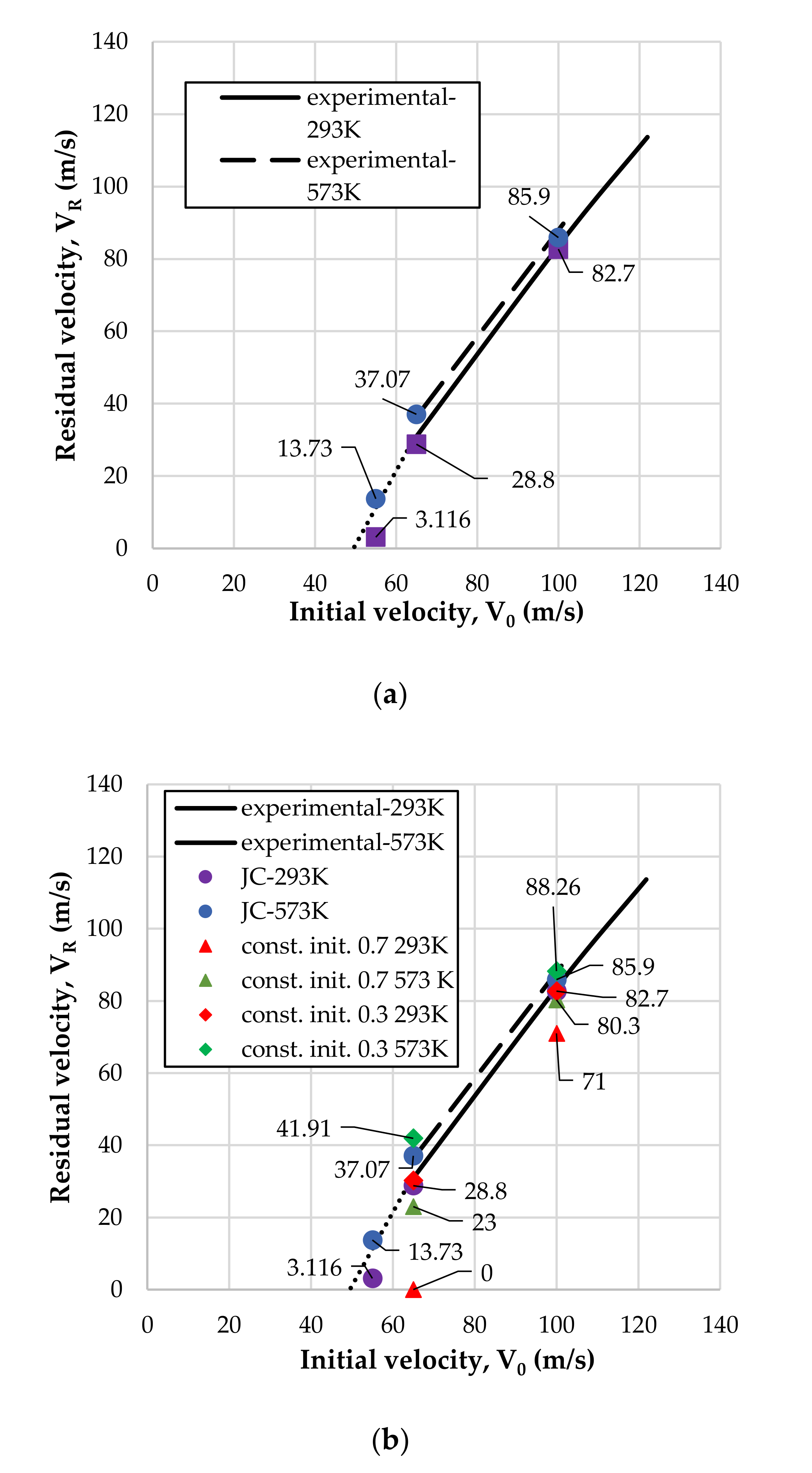
4. Results and Discussion
5. Conclusions
Author Contributions
Funding
Institutional Review Board Statement
Informed Consent Statement
Data Availability Statement
Conflicts of Interest
References
- Vlot, A. Fibre Metal Laminates: An Introduction; Kluwer Academic Publishers: Dordrecht, The Netherlands; Boston, MA, USA, 2001; p. 527. [Google Scholar]
- Vlot, A. Impact Tests on Aluminium 2024-T3, Aramid and Glass Reinforced Laminates and Thermoplastic Composites; Delft University of Technology: Delft, The Netherlands, 1987; p. 43. [Google Scholar]
- Langdon, G.S.; Lemanski, S.L.; Nurick, G.N.; Simmons, M.C.; Cantwell, W.J.; Schleyer, G.K. Behaviour of fibre-metal laminates subjected to localised blast loading: Part I—Experimental observations. Int. J. Impact Eng. 2007, 34, 1202–1222. [Google Scholar] [CrossRef]
- Carrillo, J.G.; Cantwell, W.J. Mechanical properties of a novel fibre-metal laminate based on a polypropylene composite. Mech. Mater. 2009, 41, 828–838. [Google Scholar] [CrossRef]
- Santiago, R.; Cantwell, W.; Alves, M. Impact on thermoplastic fibre-metal laminates: Experimental observations. Compos. Struct. 2017, 159, 800–817. [Google Scholar] [CrossRef]
- Santiago, R.C.; Cantwell, W.J.; Jones, N.; Alves, M. The modelling of impact loading on thermoplastic fibre-metal laminates. Compos. Struct. 2018, 189, 228–238. [Google Scholar] [CrossRef]
- Vlot, A. Glare: History of the Development of a New Aircraft Material; Kluwer Academic Publishers: Dordrecht, The Netherlands; Boston, MA, USA, 2001; p. 222. [Google Scholar]
- Sherkatghanad, E.; Lang, L.; Blala, H.; Li, L.; Alexandrov, S. Fiber Metal Laminate Structure, a good replacement for monolithic and composite materials. IOP Conf. Ser. Mater. Sci. Eng. 2019, 576, 0120349. [Google Scholar] [CrossRef]
- Borvik, T.; Clausen, A.H.; Eriksson, M.; Berstad, T.; Hopperstad, O.S.; Langseth, M. Experimental and numerical study on the perforation of AA6005–T6 panels. Int. J. Impact Eng. 2005, 32, 35–64. [Google Scholar] [CrossRef]
- Borvik, T.; Clausen, A.H.; Hopperstad, O.S.; Langseth, M. Perforation of AA5083–H116 aluminium plates with conical–nose steel projectiles-experimental study. Int. J. Impact Eng. 2004, 30, 367–384. [Google Scholar] [CrossRef]
- Gupta, N.K.; Iqbal, M.A.; Sekhon, G.S. Experimental and numerical studies on the behaviour of thin aluminum plates subjected to impact by blunt– and hemispherical–nosed projectiles. Int. J. Impact Eng. 2006, 32, 1921–1944. [Google Scholar] [CrossRef]
- Clausen, A.H.; Borvik, T.; Hopperstad, O.S.; Banallal, A. Flow and fracture characteristics of aluminium alloy AA5083–H116 as function of strain rate, temperature and triaxiality. Mater. Sci. Eng. A 2004, 364, 260–272. [Google Scholar] [CrossRef]
- Rodríguez-Martínez, J.A.; Rusinek, A.; Arias, A. Thermo-viscoplastic behaviour of 2024-T3 aluminium sheets subjected to low velocity perforation at different temperatures. Thin-Walled Struct. 2011, 49, 819–832. [Google Scholar] [CrossRef] [Green Version]
- Bendarma, A.; Jankowiak, T.; Rusinek, A.; Lodygowski, T.; Jia, B.; Miguélez, M.H.; Klosak, M. Dynamic Behavior of Aluminum Alloy Aw 5005 Undergoing Interfacial Friction and Specimen Configuration in Split Hopkinson Pressure Bar System at High Strain Rates and Temperatures. Materials 2020, 13, 4614. [Google Scholar] [CrossRef]
- Recht, R.F.; Ipson, T.W. Ballistic perforation dynamics. J. Appl. Mech. 1963, 30, 384–390. [Google Scholar] [CrossRef]
- Børvik, T.; Hopperstad, O.S.; Langseth, M.; Malo, K.A. Effect of target thickness in blunt projectile penetration of Weldox 460 E steel plates. Int. J. Impact Eng. 2003, 28, 413–464. [Google Scholar] [CrossRef] [Green Version]
- Borvik, T.; Hopperstad, O.S.; Berstad, T.; Langseth, M. A computational model of viscoplasticity and ductile damage for impact and penetration. European Journal of Mechanics. Eur. J. Mech. A Solids 2001, 20, 685–712. [Google Scholar] [CrossRef]
- Abed, F.H.; Voyiadjis, G. Adiabatic Shear Band Localizations in BCC Metals at High Strain Rates and Various Initial Temperatures. Int. J. Multiscale Comput. Eng. 2007, 5, 325–349. [Google Scholar] [CrossRef]
- Jankowiak, T.; Rusinek, A.; Wood, P. A numerical analysis of the dynamic behaviour of sheet steel perforated by a conical projectile under ballistic conditions. Finite Elem. Anal. Design 2015, 65, 39–49. [Google Scholar] [CrossRef]
- Borvik, T.; Langseth, M.; Hopperstad, O.S.; Malo, K. Perforation of 12 mm thick steel plates by 20 mm diameter projectiles with flat, hemispherical and conical noses. Part I: Experimental study. Int. J. Impact Eng. 2002, 27, 19–35. [Google Scholar] [CrossRef]
- Borvik, T.; Hopperstad, O.S.; Berstad, T.; Langseth, M. Perforation of 12 mm thick steel plates by 20 mm diameter projectiles with flat, hemispherical and conical noses. Part II: Numerical simulations. Int. J. Impact Eng. 2002, 27, 37–64. [Google Scholar] [CrossRef]
- Rodríguez-Martínez, J.A.; Pesci, R.; Rusinek, A.; Arias, A.; Zaera, R.; Pedroche, D.A. Thermo-mechanical behaviour of TRIP 1000 steel sheets subjected to low velocity perforation by conical projectiles at different temperatures. Int. J. Solids Struct. 2010, 47, 1268–1284. [Google Scholar] [CrossRef] [Green Version]
- Bendarma, A.; Jankowiak, T.; Lodygowski, T.; Rusinek, A.; Klosak, M. Experimental and numerical analysis of aluminum alloy AW5005 behaviour subjected to tension and perforation under dynamic loading. J. Theor. Appl. Mech. 2017, 55, 1219–1233. [Google Scholar] [CrossRef] [Green Version]
- Klosak, M.; Rusinek, A.; Bendarma, A.; Jankowiak, T.; Lodygowski, T. Experimental study of brass properties through perforation tests using a thermal chamber for elevated temperatures. Lat. Am. J. Solids Struct. 2018, 15, e61. [Google Scholar] [CrossRef] [Green Version]
- Rusinek, A.; Bernier, R.; Matadi Boumbimba, R.; Klosak, M.; Jankowiak, T.; Voyiadjis, G.Z. New device to capture the temperature effect under dynamic compression and impact perforation of polymers, application to PMMA. Polym. Test. 2018, 65, 1–9. [Google Scholar] [CrossRef]
- Bendarma, A.; Jankowiak, T.; Rusinek, A.; Lodygowski, T.; Klosak, M. Perforation Tests of Aluminum Alloy Specimens for a Wide Range of Temperatures Using High-Performance Thermal Chamber—Experimental and Numerical Analysis. IOP Conf. Ser. Mater. Sci. Eng. 2019, 491, 012027. [Google Scholar] [CrossRef]
- Garcia-Gonzalez, D.; Rusinek, A.; Bendarma, A.; Bernier, R.; Klosak, M.; Bahi, S. Material and structural behaviour of PMMA from low temperatures to over the glass transition: Quasi-static and dynamic loading. Polym. Test. 2020, 81, 106263. [Google Scholar] [CrossRef]
- Bendarma, A.; Gourgue, H.; Jankowiak, T.; Rusinek, A.; Kardellass, S.; Klosak, M. Perforation tests of composite structure specimens at wide range of temperatures and strain rates—Experimental analysis. Mater. Today Proc. 2020, 24, 7–10. [Google Scholar] [CrossRef]
- Jia, B.; Rusinek, A.; Pesci, R.; Bernier, R.; Bahi, S.; Bendarma, A.; Wood, P. Simple shear behavior and constitutive modeling of 304 stainless steel over a wide range of strain rates and temperatures. Int. J. Impact Eng. 2021, 154, 103896. [Google Scholar] [CrossRef]
- Atkins, A.G.; Afzal Khan, M.; Liu, J.H. Necking and radial cracking around perforations in thin sheets at normal incidence. Int. J. Impact Eng. 1998, 21, 521–539. [Google Scholar] [CrossRef]
- Kpenyigba, K.M.; Jankowiak, T.; Rusinek, A.; Pesci, R. Influence of projectile shape on dynamic behavior of steel sheet subjected to impact and perforation. Thin-Walled Struct. 2013, 65, 93–104. [Google Scholar] [CrossRef] [Green Version]
- Simulia, User Assistance 2021–Abaqus, Dassault Systèmes. 2021. Available online: www.3ds.com (accessed on 29 July 2021).
- Johnson, G.R.; Cook, W.H. A constitutive model and data for metals subjected to large strains, high strain rates and high temperatures. In Proceedings of the 7th International Symposium on Ballistics, The Hague, The Netherlands, 19–21 April 1983; Volume 21, pp. 541–547. [Google Scholar]
- Santiago, R. Desempenho ao Impacto de Laminados Fibra-Metal Utilizando Reforços Termoplásticos. Ph.D. Thesis, Polytechnic School of the University of São Paulo, São Paulo, Brazil, 2014. (In Portuguese). [Google Scholar]
- Buyuk, M.; Kan, S.; Loikkanen, M.J. Explicit Finite-Element Analysis of 2024-T3/T351 Aluminum Material under Impact Loading for Airplane Engine Containment and Fragment Shielding. J. Aerosp. Eng. 2009, 22, 287. [Google Scholar] [CrossRef]
- Teng, X.; Wierzbicki, T. Evaluation of six fracture models in high velocity perforation. Eng. Fracture Mech. 2006, 73, 1653–1678. [Google Scholar] [CrossRef]
- Johnson, G.R.; Cook, W.H. Fracture characteristics of three metals subjected to various strains, strain rates, temperatures and pressures. Eng. Fracture Mech. 1985, 21, 31–48. [Google Scholar] [CrossRef]
- Johnson, G.R.; Holmquist, T.J. Test Data and Computational Strength and Fracture Model Constants for 23 Materials Subjected to Large Strains, High Strain Rates, and High Temperatures; Los Alamos National Laboratory: Los Alamos, NM, USA, 1989. [Google Scholar]
- Massaq, A.; Rusinek, A.; Klosak, M.; Abed, F.; El Mansori, M. A study of friction between composite-steel surfaces at high impact velocities. Tribol. Int. 2016, 102, 38–43. [Google Scholar] [CrossRef]
- Klosak, M.; Jankowiak, T.; Rusinek, A.; Bendarma, A.; Sielicki, P.W.; Lodygowski, T. Mechanical Properties of Brass under Impact and Perforation Tests for a Wide Range of Temperatures: Experimental and Numerical Approach. Materials 2020, 13, 5821. [Google Scholar] [CrossRef]
- Rosenberg, Z.; Vayig, Y. On the friction effect in the perforation of metallic plates by rigid projectiles. Int. J. Impact Eng. 2021, 149, 103794. [Google Scholar] [CrossRef]
- Hayhurst, C.J.; Livingstone, I.H.G.; Clegg, R.A.; Destefanis, R.; Faraud, M. Ballistic limit evaluation of advanced shielding using numerical simulations. Int. J. Impact Eng. 2001, 26, 309–320. [Google Scholar] [CrossRef]
- Knight, N.F.; Jaunky, N.; Lawson, R.E.; Ambur, D.R. Penetration simulation for uncontained engine debris impact on fuselage–like panels using LS-Dyna. Finite Elem. Anal. Design 2000, 36, 99–133. [Google Scholar]
- Kurtaran, H.; Buyuk, M.; Eskandarian, A. Ballistic impact simulation of GT model vehicle door using finite element method. Theor. Appl. Fract. Mech. 2003, 40, 113–121. [Google Scholar] [CrossRef]


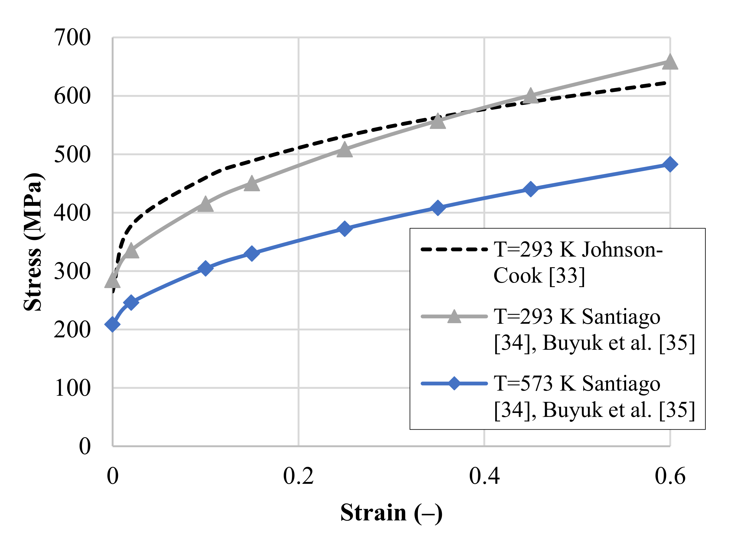
| A (MPa) | B (MPa) | n (-) | C (-) | m (-) | (K) | (K) | (l/s) | |
| 265 | 426 | 0.34 | 0.0083 | 1.7 | 293.15 | 775 | 1.0 | Johnson and Cook [33] |
| 284.9 | 504.81 | 0.5871 | 0.0083 | 1.7 | 293.15 | 900 * | 1.0 | Santiago [34], Buyuk et al. [35] |
| d1 (-) | d2 (-) | d3 (-) | d4 (-) | d5 (-) | (mm) | |||
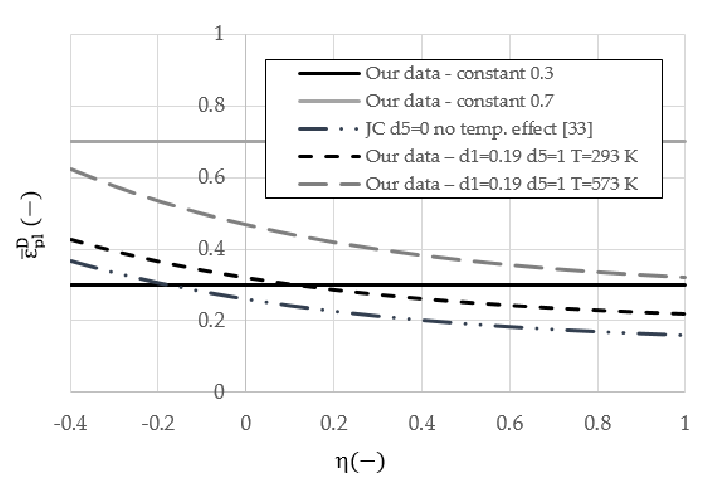
| 0.13 | 0.13 | 1.5 | 0.011 | 0 | 0.001 | Johnson and Cook [33] | ||
| 0.19 | 0.13 | 1.5 | 0.011 | 1 | 0.001 | Johnson–Cook failure criterion—our work | ||
| 0.3 or 0.7 | 0 | 0 | 0 | 0 | 0.001 | Our work—constant |
| Test Ref. | Pressure (bar) | (m/s) | (m/s) | (K) | E (J) |
|---|---|---|---|---|---|
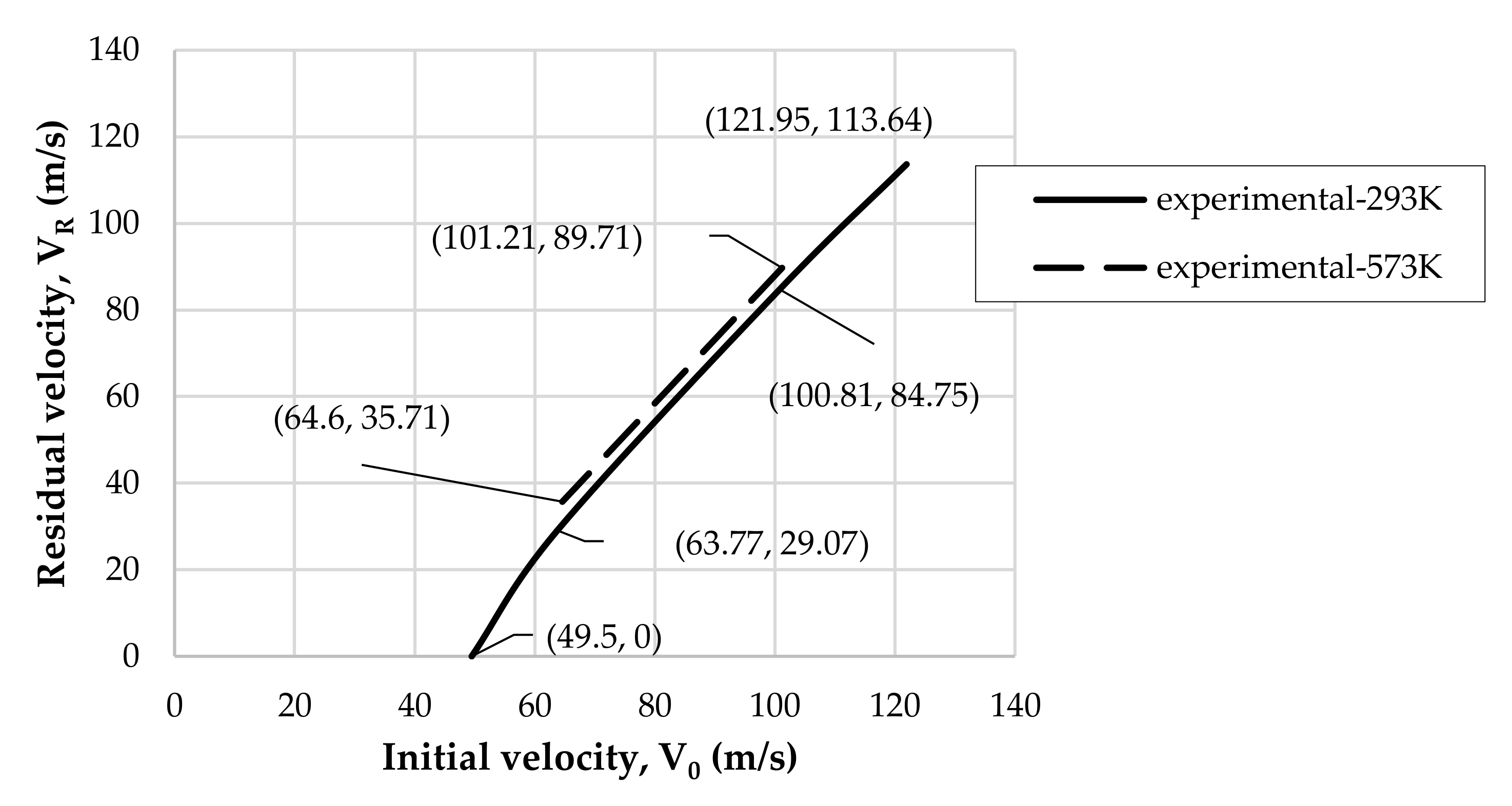
| AL08 | 1.3 | 49.5 | 0 | 293 | 10.1 |
| AL02 | 2 | 63.77 | 29.07 | 293 | 13.28 |
| AL01 | 5 | 100.81 | 84.75 | 293 | 12.28 |
| AL09 | 7.6 | 121.95 | 113.64 | 293 | 8.07 |
| AL04 | 2 | 64.94 | 35.21 | 473 | 12.27 |
| AL03 | 5 | 100.8 | 86.21 | 473 | 11.24 |
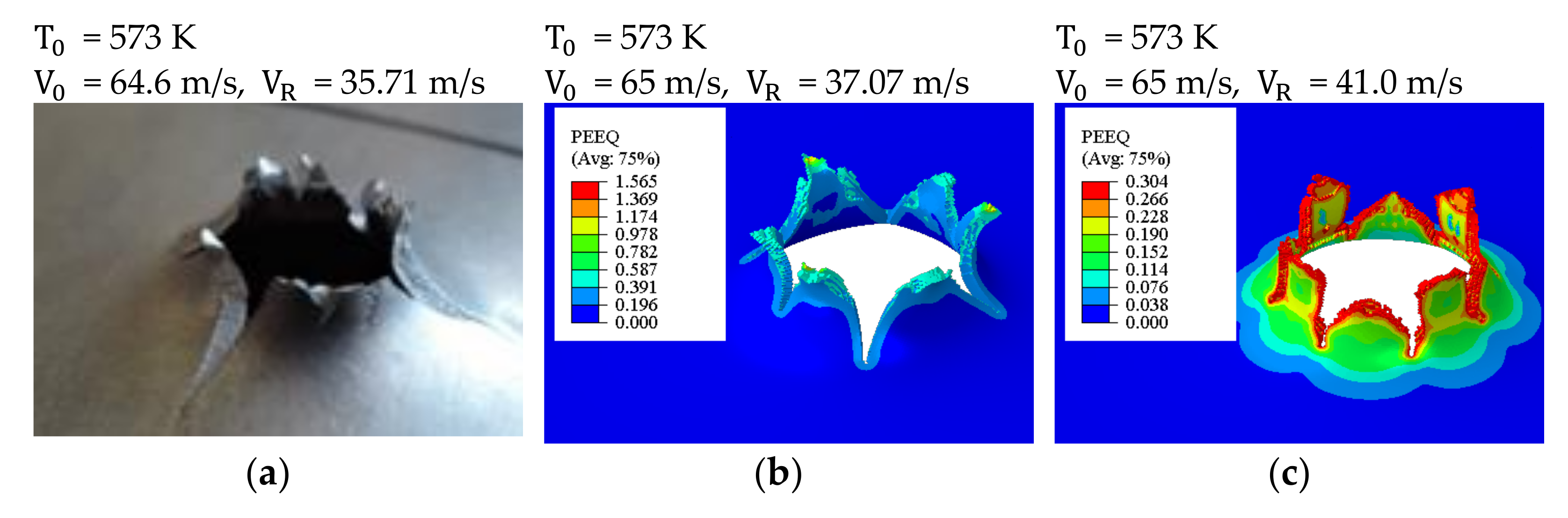
| AL07 | 2 | 64.6 | 35.71 | 573 | 11.94 |
| AL06 | 2 | 64.1 | n/a | 573 | n/a |
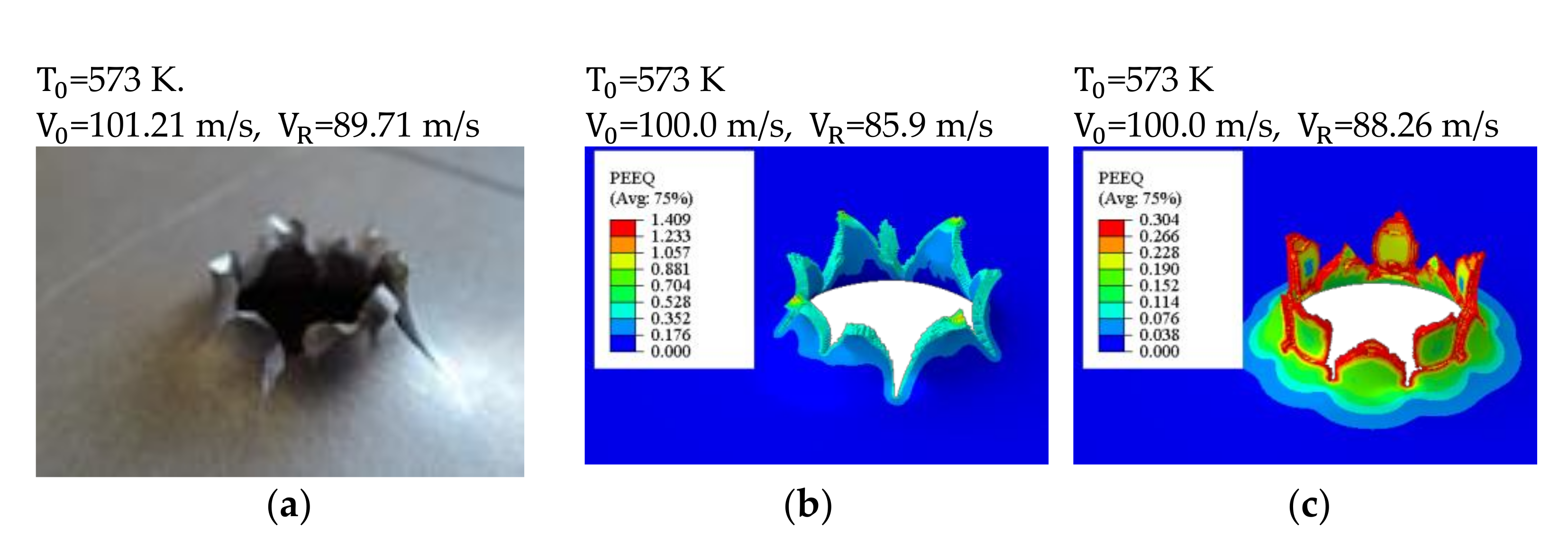
| AL05 | 5 | 101.21 | 89.71 | 573 | 9.36 |
Publisher’s Note: MDPI stays neutral with regard to jurisdictional claims in published maps and institutional affiliations. |
© 2021 by the authors. Licensee MDPI, Basel, Switzerland. This article is an open access article distributed under the terms and conditions of the Creative Commons Attribution (CC BY) license (https://creativecommons.org/licenses/by/4.0/).
Share and Cite
Klosak, M.; Santiago, R.; Jankowiak, T.; Bendarma, A.; Rusinek, A.; Bahi, S. The Influence of Temperature in the Al 2024-T3 Aluminum Plates Subjected to Impact: Experimental and Numerical Approaches. Materials 2021, 14, 4268. https://0-doi-org.brum.beds.ac.uk/10.3390/ma14154268
Klosak M, Santiago R, Jankowiak T, Bendarma A, Rusinek A, Bahi S. The Influence of Temperature in the Al 2024-T3 Aluminum Plates Subjected to Impact: Experimental and Numerical Approaches. Materials. 2021; 14(15):4268. https://0-doi-org.brum.beds.ac.uk/10.3390/ma14154268
Chicago/Turabian StyleKlosak, Maciej, Rafael Santiago, Tomasz Jankowiak, Amine Bendarma, Alexis Rusinek, and Slim Bahi. 2021. "The Influence of Temperature in the Al 2024-T3 Aluminum Plates Subjected to Impact: Experimental and Numerical Approaches" Materials 14, no. 15: 4268. https://0-doi-org.brum.beds.ac.uk/10.3390/ma14154268