The Possible Detriment of Oxygen in Creep of Alumina and Zirconia Ceramic Composites Reinforced with Graphene

 , and
, and
Abstract
:1. Introduction
2. Experimental Procedure
2.1. Starting Materials
2.2. Powder Processing Methods
- A2rGO: 98 vol.% α-alumina and 2 vol.% reduced graphene oxide.
- A6.7rGO: 93.3 vol.% α-alumina and 6.7 vol.% reduced graphene oxide.
- Z2rGO: 98 vol.% t-zirconia and 2 vol.% reduced graphene oxide.
- Z6.7rGO: 93.3 vol.% t-zirconia and 6.7 vol.% reduced graphene oxide.
2.3. Sintering
2.4. Microstructural Characterization
2.5. High-Temperature Mechanical Tests
3. Results and Discussion
3.1. Characterization of the Mixtures of Powders
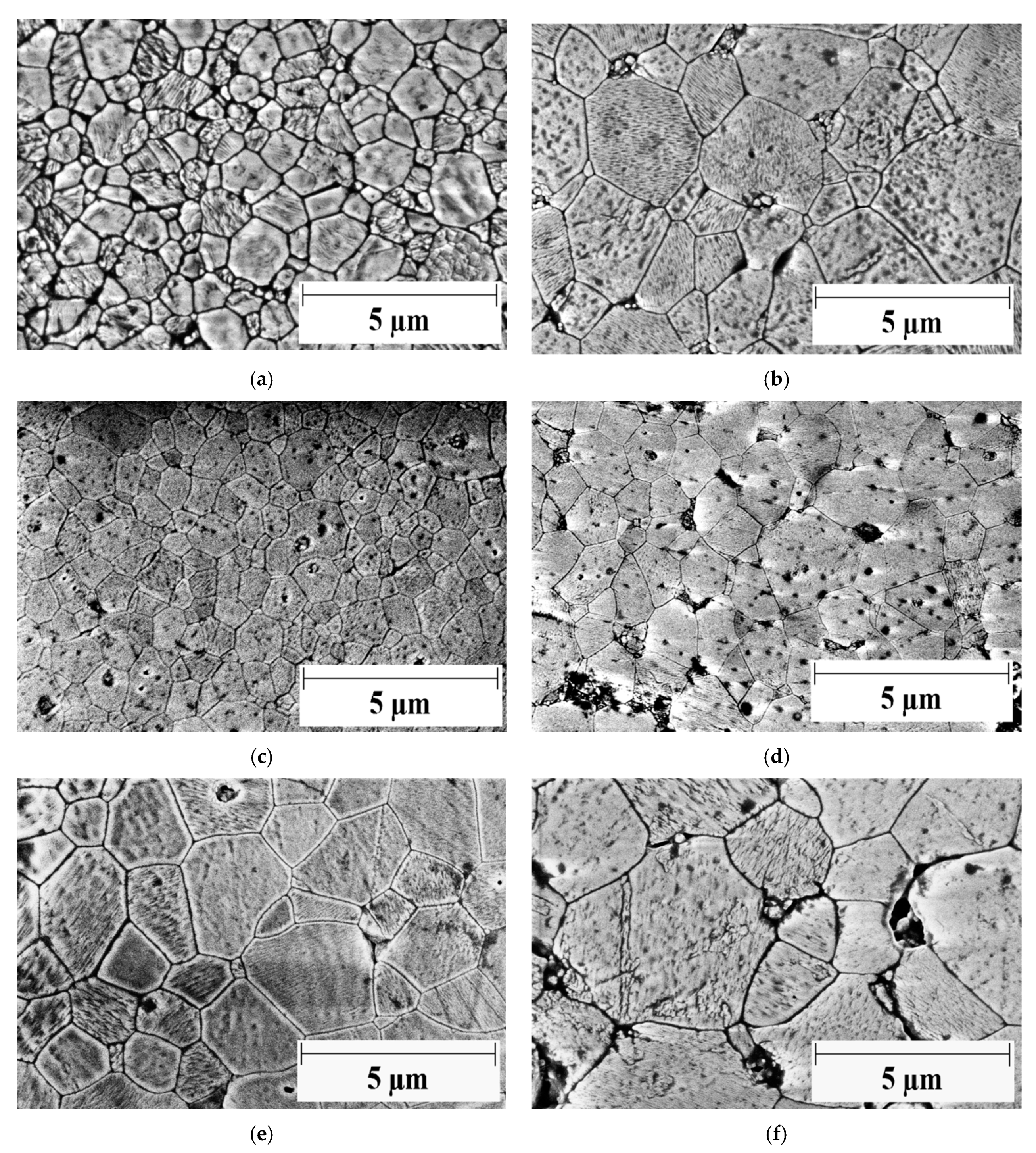
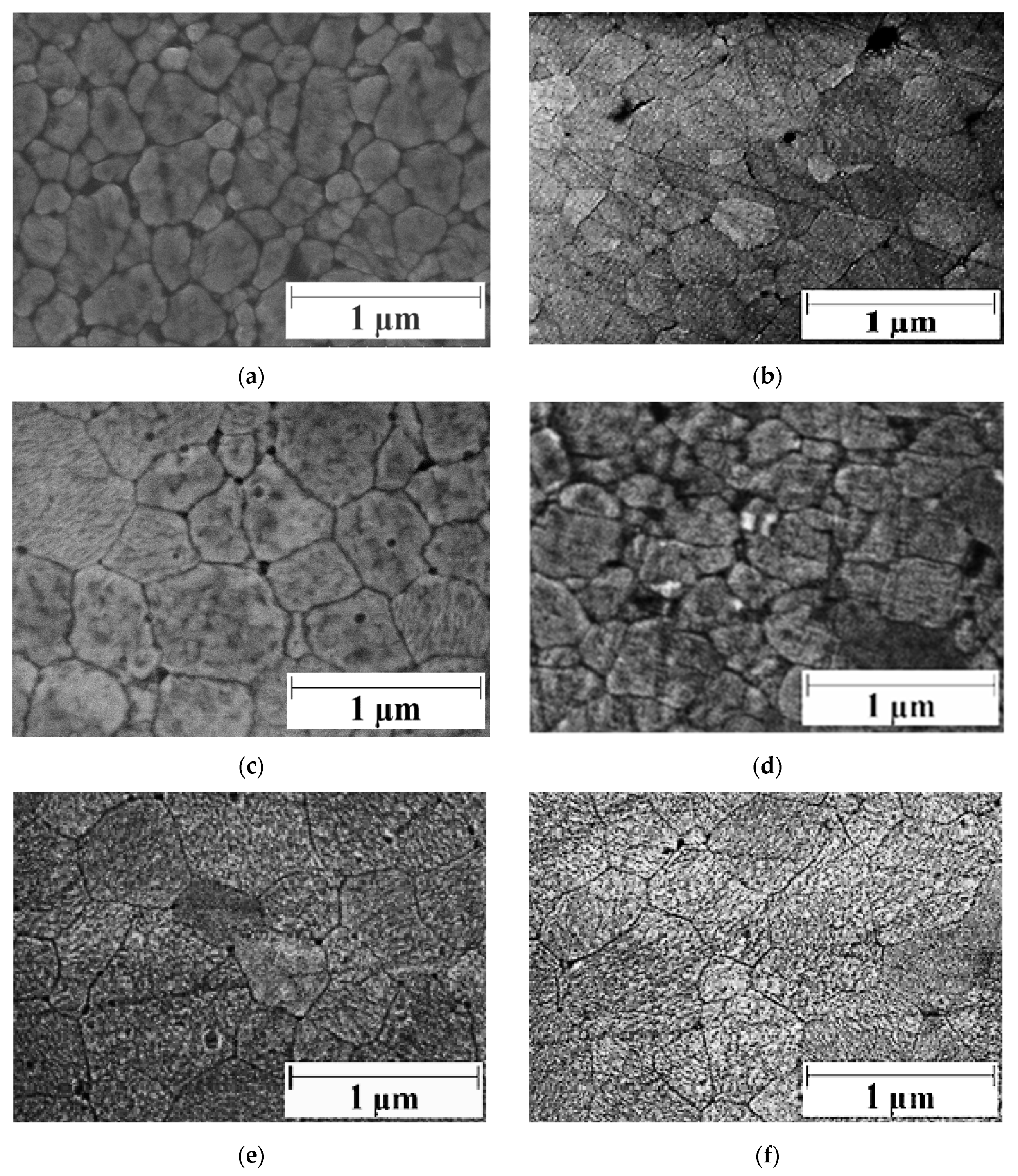
3.2. Microstructural Characterization
3.3. Analysis of the Creep Experiments
4. Conclusions
Author Contributions
Funding
Institutional Review Board Statement
Informed Consent Statement
Data Availability Statement
Acknowledgments
Conflicts of Interest
References
- Rivero-Antúnez, A.; Cano-Crespo, R.; Esquivias, L.; de la Rosa-Fox, N.; Zamora-Ledezma, C.; Domínguez-Rodríguez, A.; Morales-Flórez, V. Mechanical characterization of sol-gel alumina-based ceramics with intragranular reinforcement of multiwalled carbon nanotubes. Ceram. Int. 2020, 46, 19723–19730. [Google Scholar] [CrossRef]
- Curtin, W.A.; Sheldon, B.W. CNT-reinforced ceramics and metals. Mater. Today 2004, 7, 44–49. [Google Scholar] [CrossRef]
- Iijima, S. Helical microtubules of graphitic carbon. Nat. Cell Biol. 1991, 354, 56–58. [Google Scholar] [CrossRef]
- Endo, M.; Kim, Y.; Hayashi, T.; Nishimura, K.; Matusita, T.; Miyashita, K.; Dresselhaus, M. Vapor-grown carbon fibers (VGCFs). Carbon 2001, 39, 1287–1297. [Google Scholar] [CrossRef]
- Rodriguez, N.M. A review of catalytically grown carbon nanofibers. J. Mater. Res. 1993, 8, 3233–3250. [Google Scholar] [CrossRef]
- Zhu, Y.; Murali, S.; Cai, W.; Li, X.; Suk, J.W.; Potts, J.R.; Ruoff, R.S. Graphene and Graphene Oxide: Synthesis, Properties, and Applications. Adv. Mater. 2010, 22, 3906–3924. [Google Scholar] [CrossRef]
- Geim, A.K.; Novoselov, K.S. The rise of graphene. Nat. Mater. 2007, 6, 183–191. [Google Scholar] [CrossRef] [PubMed]
- Yang, W.; Luo, R.; Hou, Z. Effect of Interface Modified by Graphene on the Mechanical and Frictional Properties of Carbon/Graphene/Carbon Composites. Materials 2016, 9, 492. [Google Scholar] [CrossRef] [PubMed] [Green Version]
- Vajtai, R. Springer Handbook of Nanomaterials; Springer International Publishing: Heidelberg, Germany, 2013. [Google Scholar]
- Lessing, P.A.; Gordon, R.S. Creep of polycrystalline alumina, pure and doped with transition metal impurities. J. Mater. Sci. 1977, 12, 2291–2302. [Google Scholar] [CrossRef]
- Weidner, A.; Ranglack-Klemm, Y.; Zienert, T.; Aneziris, C.G.; Biermann, H. Mechanical High-Temperature Properties and Damage Behavior of Coarse-Grained Alumina Refractory Metal Composites. Materials 2019, 12, 3927. [Google Scholar] [CrossRef] [PubMed] [Green Version]
- Tamura, Y.; Moshtaghioun, B.M.; Zapata-Solvas, E.; Gomez-Garcia, D.; Domínguez-Rodríguez, A.; Cerecedo-Fernández, C.; Valcárcel-Juárez, V. Is an alumina-whisker-reinforced alumina composite the most efficient choice for an oxidation-resistant high-temperature ceramic? J. Eur. Ceram. Soc. 2018, 38, 1812–1818. [Google Scholar] [CrossRef]
- Zapata-Solvas, E.; Poyato, R.; Gómez-García, D.; Domínguez-Rodríguez, A.; Radmilovic, V.; Padture, N.P. Creep-resistant composites of alumina and single-wall carbon nanotubes. Appl. Phys. Lett. 2008, 92, 111912. [Google Scholar] [CrossRef]
- Padture, N.P. Multifunctional Composites of Ceramics and Single-Walled Carbon Nanotubes. Adv. Mater. 2009, 21, 1767–1770. [Google Scholar] [CrossRef]
- Zapata-Solvas, E.; Gómez-García, D.; Poyato, R.; Lee, Z.; Castillo-Rodríguez, M.; Domínguez-Rodriguez, A.; Radmilovic, V.; Padture, N.P. Microstructural Effects on the Creep Deformation of Alumina/Single-Wall Carbon Nanotubes Composites. J. Am. Ceram. Soc. 2010, 93, 2042–2047. [Google Scholar] [CrossRef]
- Castillo-Rodríguez, M.; Muñoz, A.; Domínguez-Rodríguez, A. Creep study on alumina and alumina/SWCNT nanocomposites. J. Eur. Ceram. Soc. 2018, 38, 5497–5502. [Google Scholar] [CrossRef]
- Heuer, A. Oxygen and aluminum diffusion in α-Al2O3: How much do we really understand? J. Eur. Ceram. Soc. 2008, 28, 1495–1507. [Google Scholar] [CrossRef]
- Bretheau, P.T.; Castaing, J.; Rabier, J.; Veyssière, P. Mouvement des dislocations et plasticité à haute température des oxydes binaires et ternaires. Adv. Phys. 1979, 28, 835–1014. [Google Scholar] [CrossRef]
- Cano-Crespo, R.; Malmal-Moshtaghioun, B.; Gómez-García, D.; Domínguez-Rodríguez, A.; Moreno, R. High-temperature creep of carbon nanofiber-reinforced and graphene oxide-reinforced alumina composites sintered by spark plasma sintering. Ceram. Int. 2017, 43, 7136–7141. [Google Scholar] [CrossRef]
- Zapata-Solvas, E.; Poyato, R.; García, D.G.; Domínguez-Rodríguez, A.; Padture, N.P. High-temperature mechanical behavior of Al2O3/graphite composites. J. Eur. Ceram. Soc. 2009, 29, 3205–3209. [Google Scholar] [CrossRef]
- Dominguez-Rodriguez, A.; García, D.G.; Wakai, F. High temperature plasticity in yttria stabilised tetragonal zirconia polycrystals (Y-TZP). Int. Mater. Rev. 2013, 58, 399–417. [Google Scholar] [CrossRef]
- Jiménez-Melendo, M.; Domínguez-Rodríguez, A.; Bravo-León, A. Superplastic Flow of Fine-Grained Yttria-Stabilized Zirconia Polycrystals: Constitutive Equation and Deformation Mechanisms. J. Am. Ceram. Soc. 2005, 81, 2761–2776. [Google Scholar] [CrossRef]
- De Bernardi-Martín, S.; Zapata-Solvas, E.; García, D.G.; Domínguez-Rodríguez, A.; Guzmán-Vázquez, F.; Gómez-Herrero, J. On the High-Temperature Plasticity of Ceria-Doped Zirconia Nanostructured Polycrystals. Key Eng. Mater. 2009, 423, 61–66. [Google Scholar] [CrossRef]
- De Bernardi-Martín, S.; García, D.G.; Domínguez-Rodríguez, A.; De Portu, G. A first study of the high-temperature plasticity of ceria-doped zirconia polycrystals. J. Eur. Ceram. Soc. 2010, 30, 3357–3362. [Google Scholar] [CrossRef]
- Calderón-Moreno, J.; De Arellano-López, A.R.; Domínguez-Rodríguez, A.; Routbort, J.L. Microstructure and creep properties of alumina/zirconia ceramics. J. Eur. Ceram. Soc. 1995, 15, 983–988. [Google Scholar] [CrossRef]
- Lorenzo-Martín, C.; Flores-Vázquez, J.; Gómez-García, D.; Muñoz-Bernabé, A.; Domínguez-Rodríguez, A.; Xueming, D.; Gomez-Herrero, J. Mechanical behaviour of yttria tetragonal zirconia polycrystalline nanoceramics: Dependence on the glassy phase content. J. Eur. Ceram. Soc. 2002, 22, 2603–2607. [Google Scholar] [CrossRef]
- Moreno, J.C.; DeArellano-López, A.; Domínguez-Rodríguez, A.; Routbort, J. High-temperature deformation of ZrO2Al2O3/SiC whisker composites fabricated by two techniques. Mater. Sci. Eng. A 1996, 209, 111–115. [Google Scholar] [CrossRef]
- Zapata-Solvas, E.; Gómez-García, D.; Domínguez-Rodríguez, A. Towards physical properties tailoring of carbon nanotubes-reinforced ceramic matrix composites. J. Eur. Ceram. Soc. 2012, 32, 3001–3020. [Google Scholar] [CrossRef]
- Cano-Crespo, R.; Moshtaghioun, B.M.; Gómez-García, D.; Moreno, R.; Domínguez-Rodríguez, A. Graphene or carbon nanofiber-reinforced zirconia composites: Are they really worthwhile for structural applications? J. Eur. Ceram. Soc. 2018, 38, 3994–4002. [Google Scholar] [CrossRef] [Green Version]
- Rincón, A.; Chinelatto, A.S.; Moreno, R. Tape casting of alumina/zirconia suspensions containing graphene oxide. J. Eur. Ceram. Soc. 2014, 34, 1819–1827. [Google Scholar] [CrossRef]
- Rincón, A.; Moreno, R.; Chinelatto, A.S.A.; Gutiérrez-González, C.F.; Rayón, E.; Salvador, M.D.; Borrell, A. Al2O3-3YTZP-Graphene multilayers produced by tape casting and spark plasma sintering. J. Eur. Ceram. Soc. 2014, 34, 2427–2434. [Google Scholar] [CrossRef]
- Poirier, J.-P. Creep of Crystals. High-Temperature Deformation Processes in Metals, Ceramics and Minerals; Cambridge University Press: Cambridge, UK, 1985. [Google Scholar]
- Dresselhaus, M.S.; Jorio, A.; Hofmann, M.; Dresselhaus, G.; Saito, R. Perspectives on Carbon Nanotubes and Graphene Raman Spectroscopy. Nano Lett. 2010, 10, 751–758. [Google Scholar] [CrossRef] [PubMed]
- Centeno, A.; Rocha, V.G.; Alonso, B.; Fernández, A.; González, C.F.G.; Torrecillas, R.; Zurutuza, A. Graphene for tough and electroconductive alumina ceramics. J. Eur. Ceram. Soc. 2013, 33, 3201–3210. [Google Scholar] [CrossRef]
- Malard, L.M.; Pimenta, M.A.; Dresselhaus, G.; Dresselhaus, M.S. Raman spectroscopy in graphene. Phys. Rep. 2009, 473, 51–87. [Google Scholar] [CrossRef]
- Durand, J.-C.; Jacquot, B.; Salehi, H.; Fages, M.; Margerit, J.; Cuisinier, F.J. Confocal Raman microscopic analysis of the zirconia/feldspathic ceramic interface. Dent. Mater. 2012, 28, 661–671. [Google Scholar] [CrossRef] [PubMed]
- Nazarpour, S.; López-Gándara, C.; Zamani, C.; Fernández-Sanjuán, J.M.; Ramos, F.M.; Cirera, A. Phase transformation studies on YSZ doped with alumina. Part 2: Yttria segregation. J. Alloy. Compd. 2010, 505, 534–541. [Google Scholar] [CrossRef]
- Kim, H.J.; Lee, S.-M.; Oh, Y.-S.; Yang, Y.-H.; Lim, Y.S.; Yoon, D.H.; Lee, C.; Kim, J.-Y.; Ruoff, R.S. Unoxidized Graphene/Alumina Nanocomposite: Fracture- and Wear-Resistance Effects of Graphene on Alumina Matrix. Sci. Rep. 2015, 4, 5176. [Google Scholar] [CrossRef] [PubMed]
- García, D.G.; Zapata-Solvas, E.; Domínguez-Rodríguez, A.; Kubin, L.P. Diffusion-driven superplasticity in ceramics: Modeling and comparison with available data. Phys. Rev. B 2009, 80, 2141071–2141078. [Google Scholar] [CrossRef] [Green Version]
- Papageorgiou, D.G.; Kinloch, I.A.; Young, R.J. Mechanical properties of graphene and graphene-based nanocomposites. Prog. Mater. Sci. 2017, 90, 75–127. [Google Scholar] [CrossRef]


| Sample | Grain Size (μm) As-Sintered | Grain Size (μm) After Creep | Shape Factor As-Sintered | Shape Factor After Creep |
|---|---|---|---|---|
| A | 0.6 ± 0.3 | 1.7 ± 0.8 | 0.7 ± 0.1 | 0.7 ± 0.1 |
| A2rGO | 0.7 ± 0.3 | 1.0 ± 0.4 | 0.7 ± 0.1 | 0.7 ± 0.1 |
| A6.7rGO | 1.4 ± 0.6 | 2.4 ± 1.2 | 0.7 ± 0.1 | 0.7 ± 0.1 |
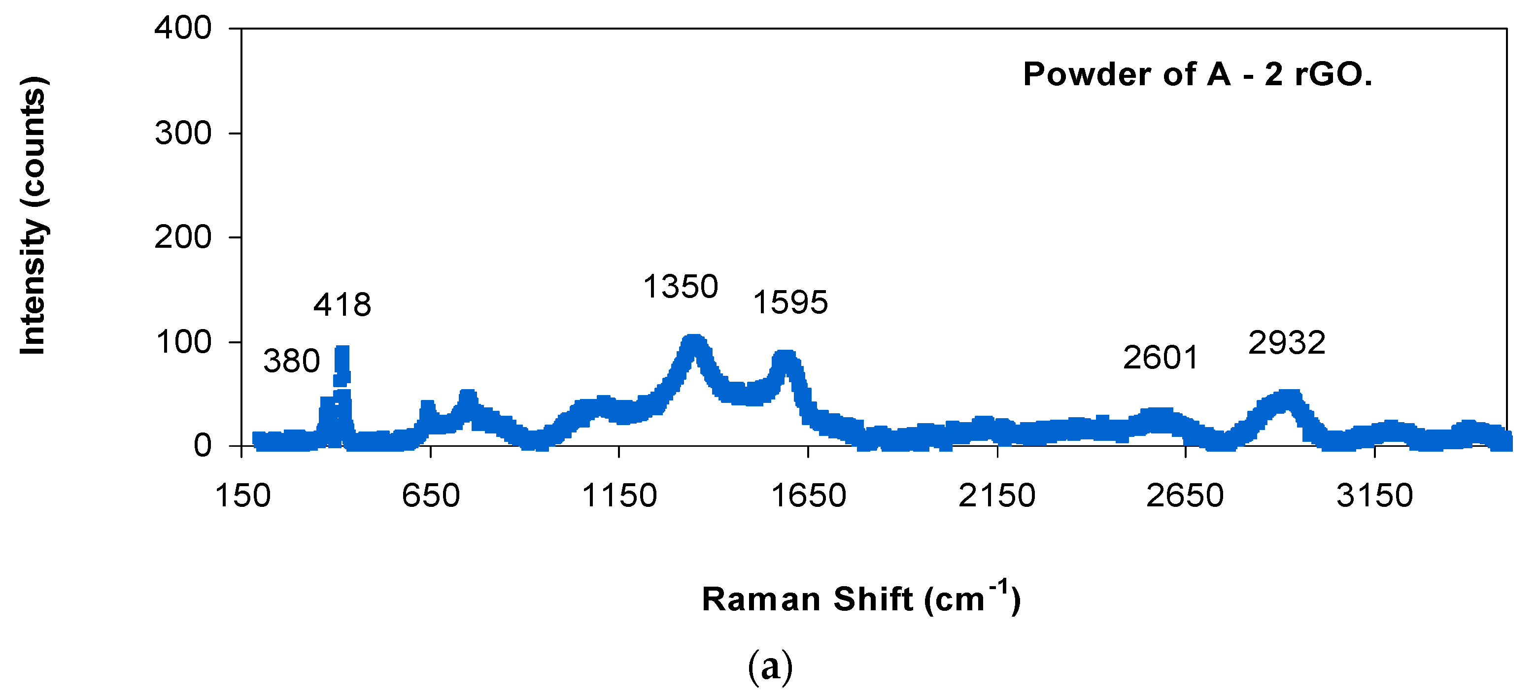
| Samples | α-Al2O3 Peak (cm−1) | α-Al2O3 Peak (cm−1) | D Peak (cm−1) | G Peak (cm−1) | 2D Peak (cm−1) | D + G Peak (cm−1) | ID/IG |
|---|---|---|---|---|---|---|---|
| A2rGO powder | 380 | 418 | 1350 | 1595 | 2601 | 2932 | 1.18 ± 0.03 |
| A2rGO sintered specimen | 378 | 420 | 1354 | 1602 | 2625 | 2886 | 0.86 ± 0.06 |
| A2rGO after creep | 375 | 414 | 1353 | 1592 | 2687 | 2904 | 0.71 ± 0.02 |
| A6.7rGO powder | 377 | 414 | 1350 | 1598 | 2599 | 2915 | 1.07 ± 0.01 |
| A6.7rGO sintered specimen | 380 | 420 | 1351 | 1586 | 2699 | 2920 | 0.41 ± 0.01 |
| A6.7rGO after creep | 380 | 423 | 1353 | 1587 | 2699 | 2926 | 0.70 ± 0.01 |
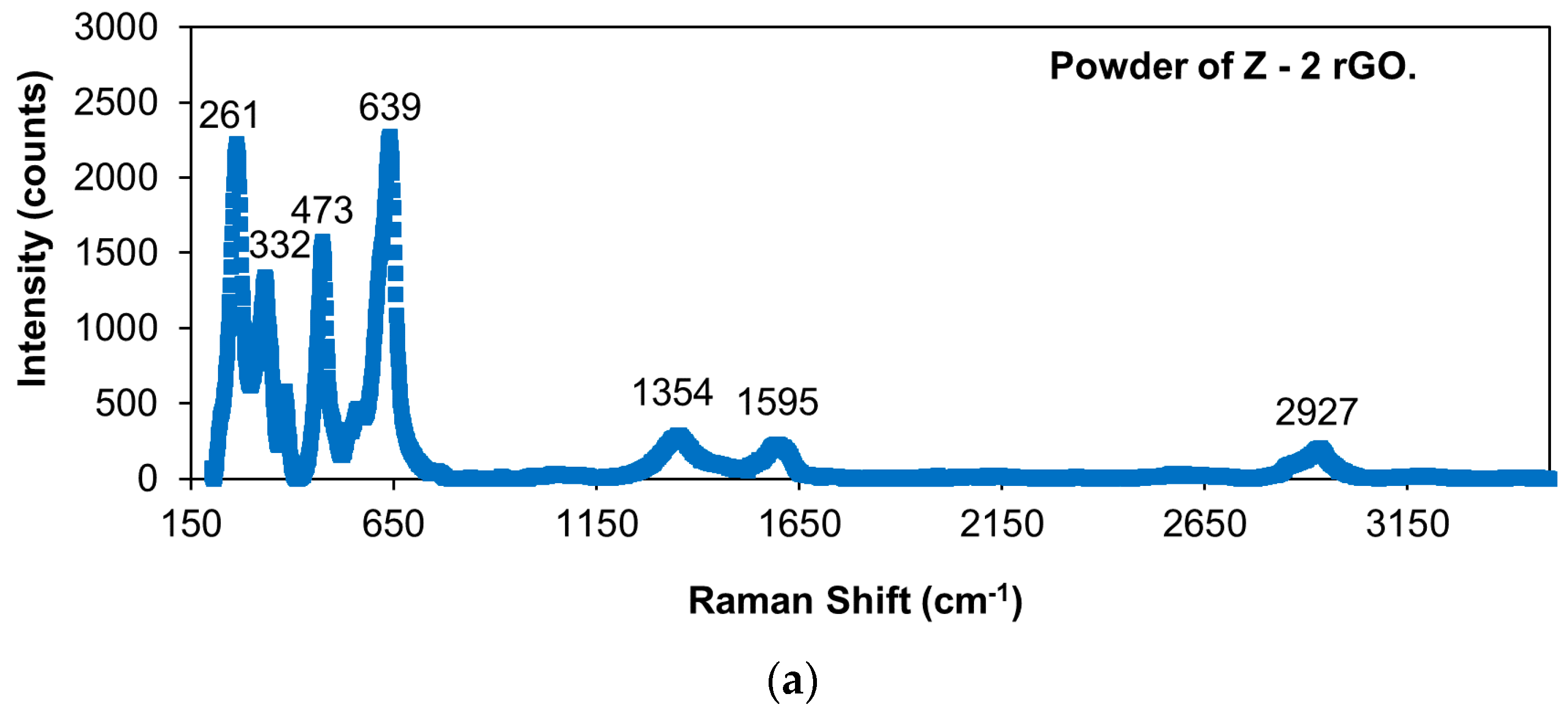
| Samples | ZrO2 Peak (cm−1) | ZrO2 Peak (cm−1) | ZrO2 Peak (cm−1) | ZrO2 Peak (cm−1) | D Peak (cm−1) | G Peak (cm−1) | 2D Peak (cm−1) | D + G Peak (cm−1) | ID/IG |
|---|---|---|---|---|---|---|---|---|---|
| Z2rGO powder | 261 | 332 | 473 | 639 | 1354 | 1595 | - | 2927 | 1.25 ± 0.01 |
| Z2rGO sintered specimen | 261 | 328 | 466 | 642 | 1338 | 1590 | 2648 | 2900 | 1.14 ± 0.04 |
| Z2rGO after creep | 261 | 322 | 463 | 644 | 1350 | 1596 | 2691 | 2917 | 0.86 ± 0.02 |
| Z6.7rGO powder | 261 | 331 | 473 | 638 | 1350 | 1590 | - | 2926 | 1.19 ± 0.02 |
| Z6.7rGO sintered specimen | 261 | 325 | 466 | 642 | 1341 | 1593 | 2688 | 2921 | 1.02 ± 0.04 |
| Z6.7rGO after creep | 261 | 317 | 463 | 644 | 1351 | 1589 | 2699 | 2935 | 0.81 ± 0.02 |
Publisher’s Note: MDPI stays neutral with regard to jurisdictional claims in published maps and institutional affiliations. |
© 2021 by the authors. Licensee MDPI, Basel, Switzerland. This article is an open access article distributed under the terms and conditions of the Creative Commons Attribution (CC BY) license (http://creativecommons.org/licenses/by/4.0/).
Share and Cite
Cano-Crespo, R.; Rivero-Antúnez, P.; Gómez-García, D.; Moreno, R.; Domínguez-Rodríguez, A. The Possible Detriment of Oxygen in Creep of Alumina and Zirconia Ceramic Composites Reinforced with Graphene. Materials 2021, 14, 984. https://0-doi-org.brum.beds.ac.uk/10.3390/ma14040984
Cano-Crespo R, Rivero-Antúnez P, Gómez-García D, Moreno R, Domínguez-Rodríguez A. The Possible Detriment of Oxygen in Creep of Alumina and Zirconia Ceramic Composites Reinforced with Graphene. Materials. 2021; 14(4):984. https://0-doi-org.brum.beds.ac.uk/10.3390/ma14040984
Chicago/Turabian StyleCano-Crespo, Rafael, Pedro Rivero-Antúnez, Diego Gómez-García, Rodrigo Moreno, and Arturo Domínguez-Rodríguez. 2021. "The Possible Detriment of Oxygen in Creep of Alumina and Zirconia Ceramic Composites Reinforced with Graphene" Materials 14, no. 4: 984. https://0-doi-org.brum.beds.ac.uk/10.3390/ma14040984