
Effect of Various Type of Nanoparticles on Mechanical and Tribological Properties of Wear-Resistant PEEK + PTFE-Based Composites

 ,
,  , ,
, , 
Abstract
:1. Introduction
2. Materials and Methods
- (1)
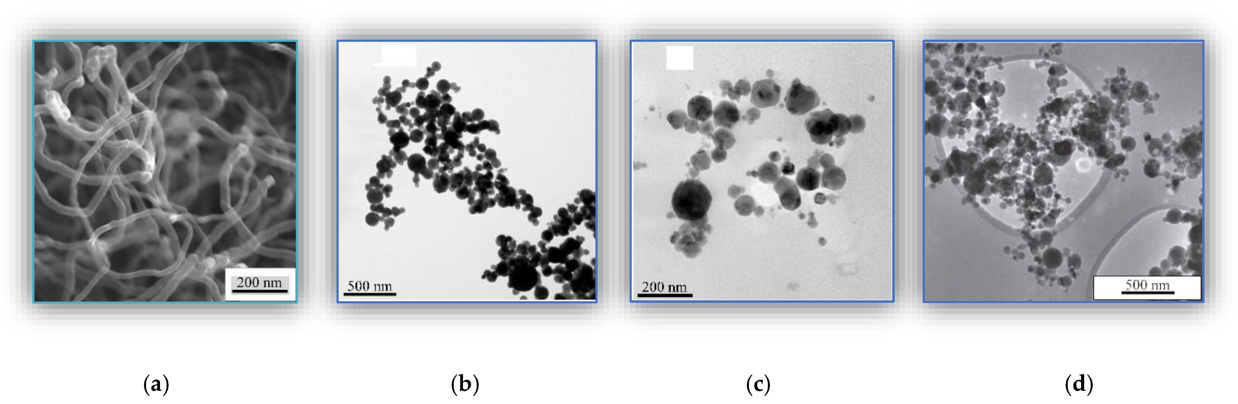
- Carbonaceous—the “Taunit” CNF (multiwall tubes) with an outer diameter of 60 nm and a length of 2–3 μm obtained by the gas-phase chemical deposition (NanoTechCenter LLC, Tambov, Russia), Figure 1a.
- (2)
- (3)
- Bimetal oxide—copper ferrite (CuFe2O4) nanoparticles with a size of 34 ± 1 nm obtained by the exploding wire method (EWM), Figure 1c.
- (4)
- Ceramic—the “Tarkosil” silicon dioxide (SiO2) nanoparticles with sizes of 25–35 nm fabricated by evaporating initial substances in an electron accelerator, Figure 1d.
3. Results and Discussion
3.1. The PEEK-Based Composites Loaded with 0.3 wt.% Nanoparticles
3.2. The PEEK-Based Composites Loaded with 7 wt.% Nanoparticles
3.3. Three-Component PEEK-Based Composites Loaded with PTFE and the Nanofillers
- (1)
- Density of the three-component composites increased by loading with the nanofillers.
- (2)
- Their Shore D hardness decreased by 3–4 units compared to that of neat PEEK and was at the level of the “PEEK/10PTFE” composite.
- (3)
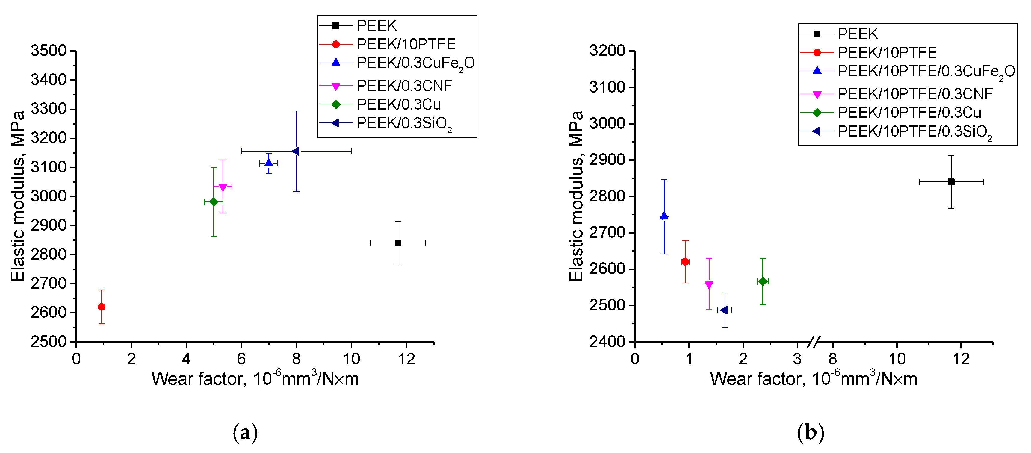
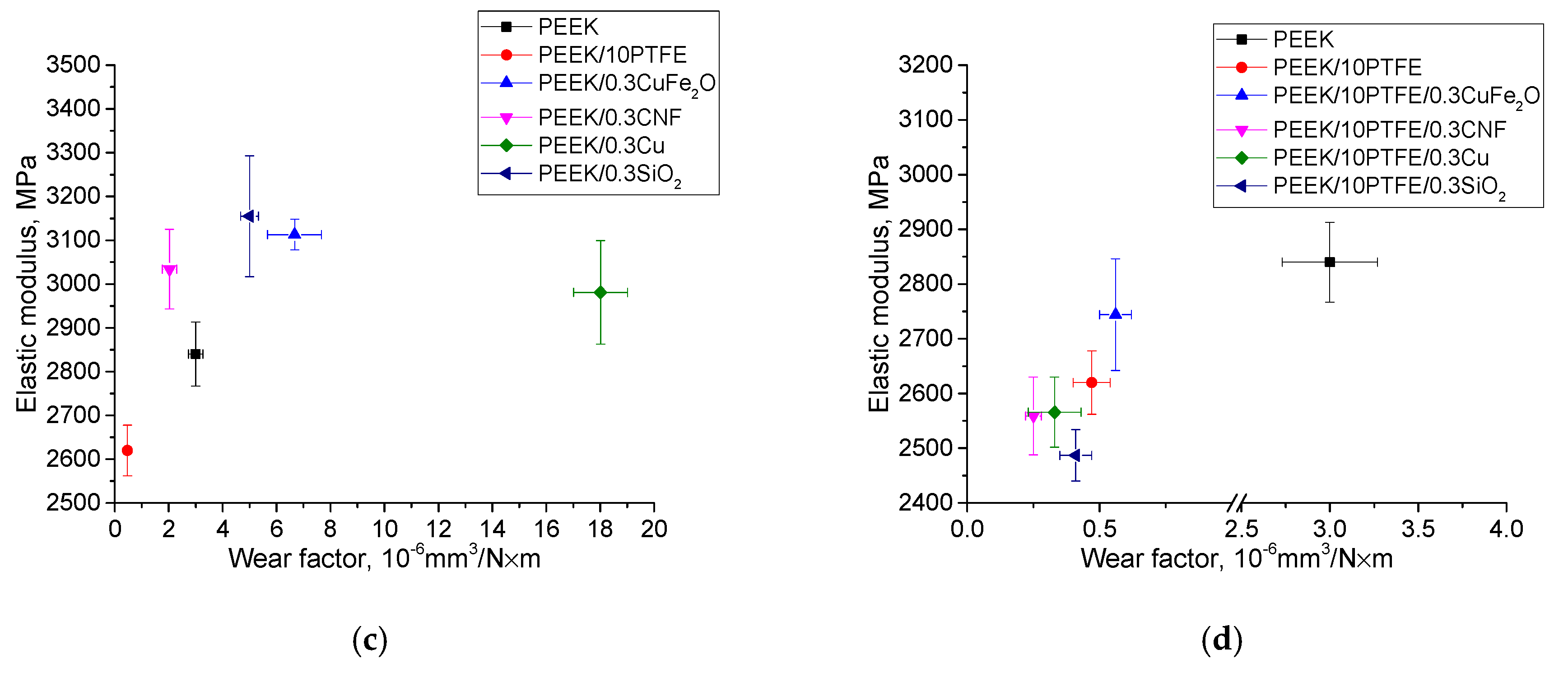
- The elastic modulus decreased slightly (down to 10%) by loading with CNF, Cu, and SiO2, and increased by filling with CuFe2O4 (up to 10%), as compared to that of the “PEEK/10PTFE” composite.
- (4)
- Tensile strength increased by loading with the nanofillers—the “PEEK/10PTFE/0.3CuFe2O4” composite possessed the maximum value of 95.5 MPa, which was 12 MPa higher, compared to that of the “PEEK/10PTFE” composite.
- 5)
- The values of elongation at break also increased by Δε = 3–5%, due to loading with the nanofillers compared to that of the “PEEK/10PTFE” composite.
3.4. Interpritation of Results
4. Conclusions
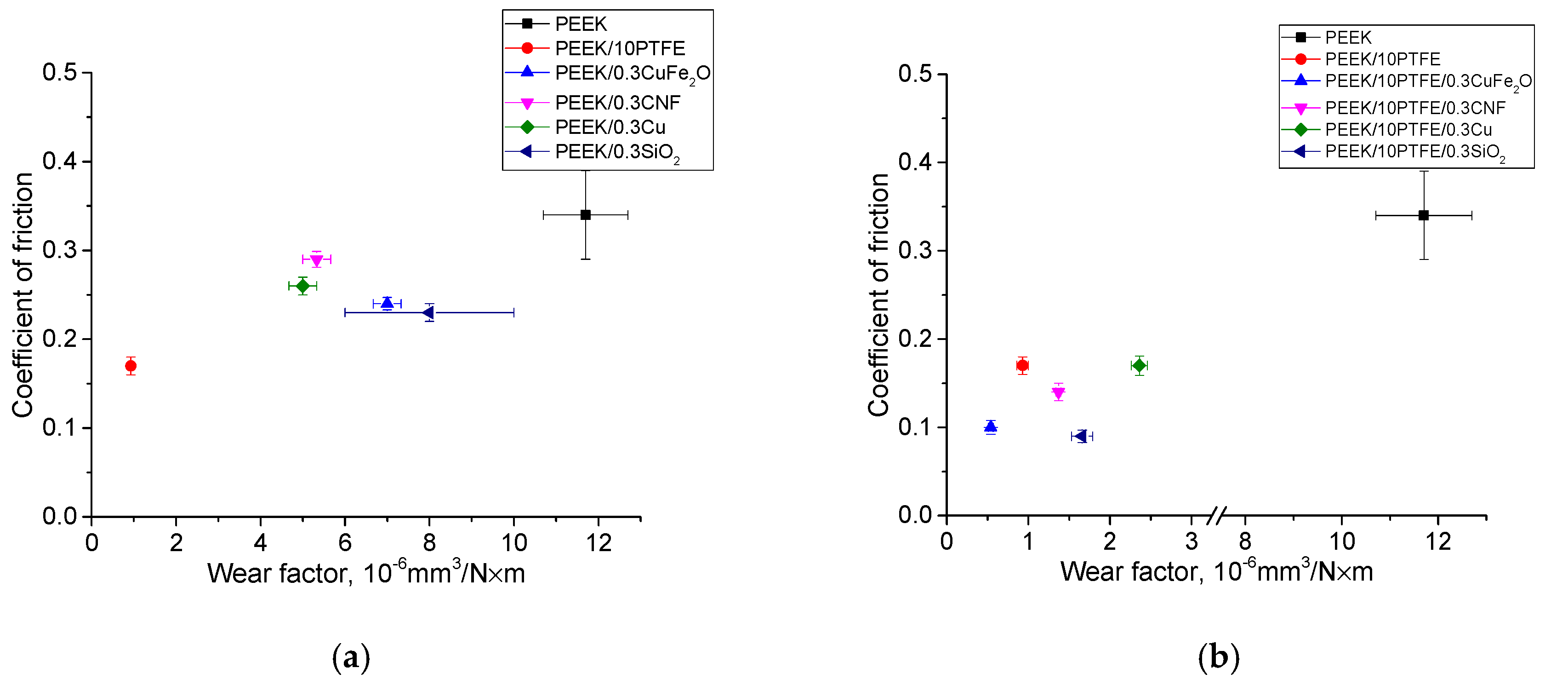
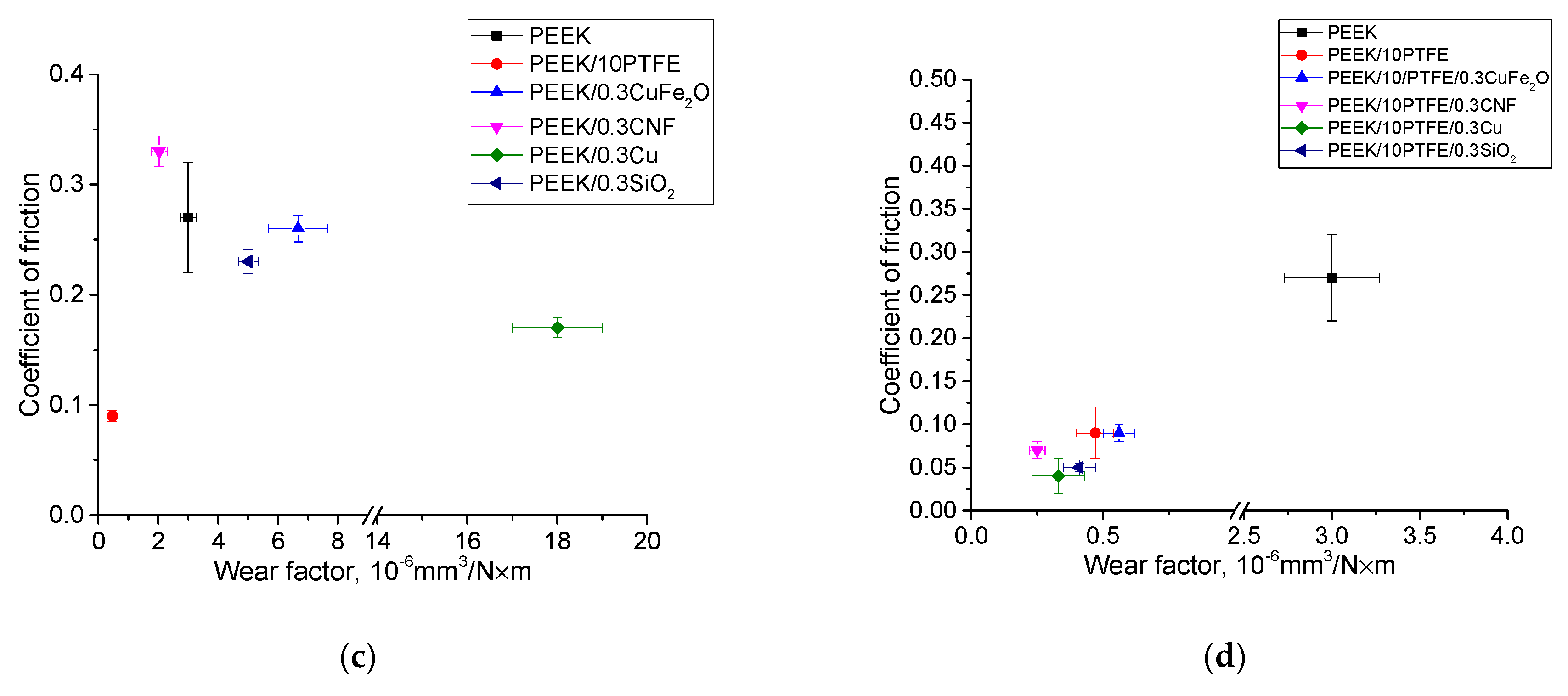
- It was shown that loading with CNF, Cu, SiO2, and CuFe2O4 nanoparticles in the small content (0.3 wt.%) enabled improvement of the elastic modulus of the PEEK-based composites by 10–15%. Wear resistance of the composites loaded with 0.3 wt.% of the nanofillers increased by 1.5–2.3 times in the metal–polymer tribological contact. This was due to the polymer transfer film formation on the steel counterpart. In the ceramic–polymer tribological contact, loading PEEK with metal nanoparticles caused the intensification of the oxidation processes, the abrasive counterpart wear, and the multiple increases in wear rate. This was accompanied by the polymer transfer film formation on the counterpart, but was not able to improve the wear resistance compared to that of neat PEEK.
- The formation of the transfer film from the PEEK-based nanocomposite debris on the steel counterpart surface was determined by its supermolecular structure, which is susceptible to destruction, while the ability to fix it depended on the activity of nanoparticles. In the case of CNF and Cu, the transfer film on the counterpart was less oxidized, which reduced the wear rate of the polymer composite. In the tribological tests of the PEEK-based composites loaded with SiO2 and CuFe2O4 nanoparticles, the transfer film was more oxidized. This caused more intense damages and wear of the polymer nanocomposite friction surface.
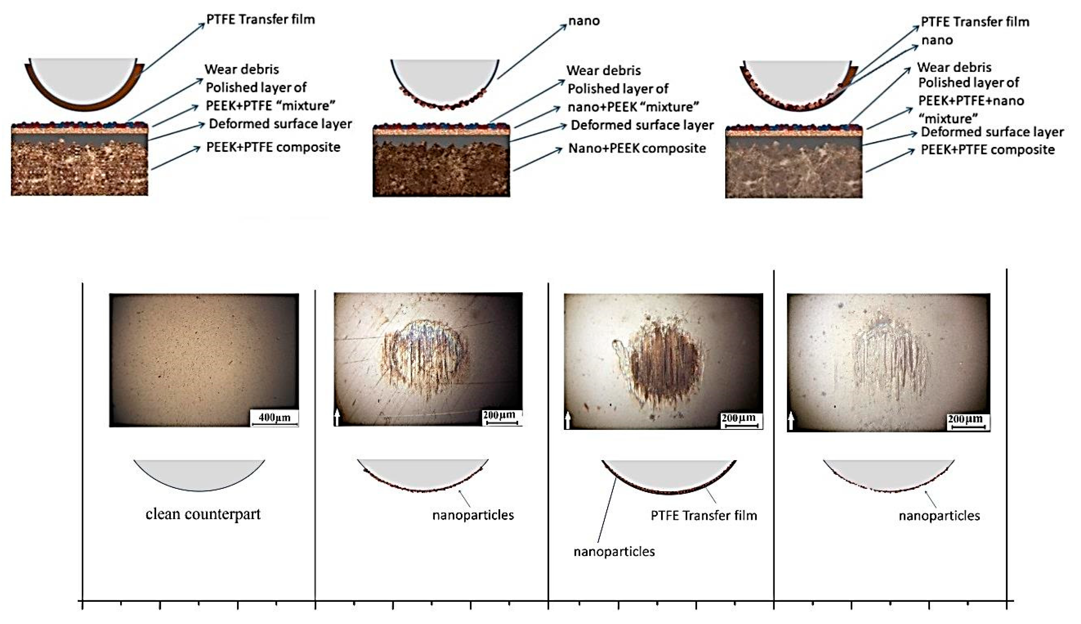
- The three-component PEEK-based composites loaded with PTFE and nanoparticles, with the slight decrease in the mechanical properties, provided an increase in wear resistance under the dry sliding friction conditions by up to 22 times in the metal–polymer tribological contact, and up to 12 times (at the wear-free level) in the ceramic-polymer one, compared to that of the neat PEEK. In all cases, this was achieved by the PTFE containing transfer film formation and adhering to the counterpart.
- The dispersed hardening effect was not pronounced in the three-component PEEK-based composites loaded with nanofillers, unlike the case of the two-component ones. Due to the predominant agglomeration of nanoparticles within PTFE inclusions, they were easier separated and transferred to the counterpart surface. Then, the transfer film adhered on the counterpart surface due to the PEEK tribological oxidation resulted in improved wear resistance, compared to the “PEEK/10PTFE” composite.
- In the "PEEK/10PTFE/0.3 nanofiller” composite, the nanoparticles served a dual function—(i) adhesion of the transfer film to the counterpart and (ii) dispersed hardening, which increased the deformation and strength properties (tensile strength, elongation), as compared to the “PEEK/10PTFE” composite. The nanofiller type (its composition) determined the tribological oxidation level and, as a consequence, also determined the formation and adherence of the transfer film on the counterpart.
Author Contributions
Funding
Data Availability Statement
Conflicts of Interest
References
- Bajpai, A.; Saxena, P.; Kunze, K. Tribo-Mechanical Characterization of Carbon Fiber-Reinforced Cyanate Ester Resins Modified With Fillers. Polymers 2020, 12, 1725. [Google Scholar] [CrossRef]
- Vazirisereshk, M.R.; Martini, A.; Strubbe, D.A.; Baykara, M.Z. Solid Lubrication with MoS2: A Review. Lubricants 2019, 7, 57. [Google Scholar] [CrossRef] [Green Version]
- Feng, Q.; Zou, S.; Li, H.; Dou, M.; Huang, F. Review of Polymer Self-lubricating Coatings. IOP Conf. Ser. Earth Environ. Sci. 2020, 526, 012077. [Google Scholar] [CrossRef]
- Lu, Z.P.; Friedrich, K. On sliding friction and wear of PEEK and its composites. Wear 1995, 181–183, 624–631. [Google Scholar] [CrossRef]
- Hufenbach, W.; Kunze, K.; Bijie, J. Sliding wear behaviour of PEEK-PTFE blends. J. Synth. Lubr. 2003, 20, 227–240. [Google Scholar] [CrossRef]
- Bijwe, J.; Sen, S.; Ghosh, A. Influence of PTFE content in PEEK–PTFE blends on mechanical properties and tribo-performance in various wear modes. Wear 2005, 258, 1536–1542. [Google Scholar] [CrossRef]
- Vail, J.R.; Krick, B.A.; Marchman, K.R.; Sawyer, W.G. Polytetrafluoroethylene (PTFE) fiber reinforced polyetheretherketone (PEEK) composites. Wear 2011, 270, 737–741. [Google Scholar] [CrossRef]
- Burris, D.L.; Sawyer, W.G. Tribological behavior of PEEK components with compositionally graded PEEK/PTFE surfaces. Wear 2007, 262, 220–224. [Google Scholar] [CrossRef]
- Xie, G.Y.; Zhuang, G.S.; Sui, G.X.; Yang, R. Tribological behavior of PEEK/PTFE composites reinforced with potassium titanate whiskers. Wear 2010, 268, 424–430. [Google Scholar] [CrossRef]
- Liu, L.; Yan, F.; Gai, F.; Xiao, L.; Shang, L.; Li, M.; Ao, Y. Enhanced tribological performance of PEEK/SCF/PTFE hybrid composites by graphene. RSC Adv. 2017, 7, 33450–33458. [Google Scholar] [CrossRef] [Green Version]
- Vande Voort, J.; Bahadur, S. The growth and bonding of transfer film and the role of CuS and PTFE in the tribological behavior of PEEK. Wear 1995, 181–183, 212–221. [Google Scholar] [CrossRef]
- Rodriguez, V.; Sukumaran, J.; Schlarb, A.K.; De Baets, P. Influence of solid lubricants on tribological properties of polyetheretherketone (PEEK). Tribol. Int. 2016, 103, 45–57. [Google Scholar] [CrossRef]
- Lin, L.; Schlarb, A.K. Tribological response of the PEEK/SCF/graphite composite by releasing rigid particles into the tribosystem. Tribol. Int. 2019, 137, 173–179. [Google Scholar] [CrossRef]
- Zhang, Z.; Breidt, C.; Chang, L.; Friedrich, K. Wear of PEEK composites related to their mechanical performances. Tribol. Int. 2004, 37, 271–277. [Google Scholar] [CrossRef]
- Buckley, D.H.; Johnson, R.L. Friction, Wear and Decomposition Mechanisms for Various Polymer Compositions in Vacuum to 10-9 Millimeter of Mercury; NASA-TN-D-2073; NASA Technical Note; Lewis Research Center: Cleveland, OH, USA, 1963. [Google Scholar]
- Yen, B.K.; Schwickert, B.E.; Toney, M.F. Origin of low-friction behavior in graphite investigated by surface x-ray diffraction. Appl. Phys. Lett. 2004, 84, 4702–4704. [Google Scholar] [CrossRef] [Green Version]
- Rouhi, M.; Moazami-goudarzi, M.; Ardestani, M. Comparison of effect of SiC and MoS2 on wear behavior of Al matrix composites. Trans. Nonferr. Met. Soc. China 2019, 29, 1169–1183. [Google Scholar] [CrossRef]
- Zalaznik, M.; Kalin, M.; Novak, S.; Jakša, G. Effect of the type, size and concentration of solid lubricants on the tribological properties of the polymer PEEK. Wear 2016, 364–365, 31–39. [Google Scholar] [CrossRef]
- Wang, A.H.; Xia, J.; Yang, Z.X.; Xiong, D.H. A novel assembly of MoS2-PTFE solid lubricants into wear-resistant micro-hole array template and corresponding tribological performance. Opt. Laser Technol. 2019, 116, 171–179. [Google Scholar] [CrossRef]
- Kato, H.; Takama, M.; Iwai, Y.; Washida, K.; Sasaki, Y. Wear and mechanical properties of sintered copper–tin composites containing graphite or molybdenum disulfide. Wear 2003, 255, 573–578. [Google Scholar] [CrossRef]
- Rapoport, L.; Moshkovich, A.; Perfilyev, V.; Lapsker, I.; Halperin, G.; Itovich, Y.; Etsion, I. Friction and wear of MoS2 films on laser textured steel surfaces. Surf. Coat. Technol. 2008, 202, 3332–3340. [Google Scholar] [CrossRef]
- Cho, M.H.; Bahadur, S.; Pogosian, A.K. Friction and wear studies using Taguchi method on polyphenylene sulfide filled with a complex mixture of MoS2, Al2O3, and other compounds. Wear 2005, 258, 1825–1835. [Google Scholar] [CrossRef]
- Yang, Z.; Guo, Z.; Yuan, C. Effects of MoS2 microencapsulation on the tribological properties of a composite material in a water-lubricated condition. Wear 2019, 432–433, 102919. [Google Scholar] [CrossRef]
- Theiler, G.; Gradt, T. Friction and wear of PEEK composites in vacuum environment. Wear 2010, 269, 278–284. [Google Scholar] [CrossRef]
- Bahadur, S.; Gong, D. The role of copper compounds as fillers in the transfer and wear behavior of polyetheretherketone. Wear 1992, 154, 151–165. [Google Scholar] [CrossRef]
- Bahadur, S.; Tabor, D. The wear of filled polytetrafluoroethylene. Wear 1984, 98, 1–13. [Google Scholar] [CrossRef]
- Zhao, Q.; Bahadur, S. The mechanism of filler action and the criterion of filler selection for reducing wear. Wear 1999, 225–229, 660–668. [Google Scholar] [CrossRef]
- Zhao, Q.; Bahadur, S. A study of the modification of the friction and wear behavior of polyphenylene sulfide by particulate Ag2S and PbTe fillers. Wear 1998, 217, 62–72. [Google Scholar] [CrossRef]
- Schwartz, C.; Bahadur, S. The role of filler deformability, filler–polymer bonding, and counterface material on the tribological behavior of polyphenylene sulfide (PPS). Wear 2001, 251, 1532–1540. [Google Scholar] [CrossRef]
- Wang, Q.; Xu, J.; Shen, W.; Liu, W. An investigation of the friction and wear properties of nanometer Si3N4 filled PEEK. Wear 1996, 196, 82–86. [Google Scholar] [CrossRef]
- Wang, Q.H.; Xue, Q.; Shen, W. The friction and wear properties of nanonometre SiO2 filled polyetheretherketone. Tribol. Int. 1997, 30, 193–197. [Google Scholar] [CrossRef]
- Wang, Q.-H.; Xu, J.; Shen, W.; Xue, Q. The effect of nanometer SiC filler on the tribological behavior of PEEK. Wear 1997, 209, 316–321. [Google Scholar] [CrossRef]
- Schwartz, C.J.; Bahadur, S. Studies on the tribological behaviour and transfer film-counterface bond strength for polyphenylene sulfide filled with nanoscale alumina particles. Wear 2000, 237, 261–273. [Google Scholar] [CrossRef]
- Bahadur, S.; Sunkara, C. Effect of transfer film structure, composition and bonding on thetribological behaviour of polyphenylene sulfide filled with nano particles of TiO2, ZnO, CuO and SiC. Wear 2005, 258, 1411–1421. [Google Scholar] [CrossRef]
- Ruckdäschel, H.; Sandler, J.K.W.; Altstädt, V. On the friction and wear of carbon nanofiber–reinforced PEEK–based polymer composites. Tribol. Interface Eng. Ser. 2008, 55, 149–208. [Google Scholar] [CrossRef]
- Sandler, J.; Werner, P.; Shaffer MS, P.; Demchuk, V.; Altstadt, V.; Windle, A.H. Carbon-nanofibre-reinforced poly(ether ether ketone) composites. Compos. Part A Appl. Sci. Manuf. 2002, 33, 1033–1039. [Google Scholar] [CrossRef]
- Werner, P.; Altstadt, V.; Jaskulka, R.; Jacobs, O.; Sandler JK, W.; Shaffer MS, P.; Windle, A.H. Tribological behaviour of carbon-nanofibre-reinforced poly(ether ether ketone). Wear 2004, 257, 1006–1014. [Google Scholar] [CrossRef]
- Modi, S.H.; Dikovics, K.B.; Gevgilili, H.; Mago, G.; Bartolucci, S.F.; Fisher, F.T.; Kalyon, D.M. Nanocomposites of poly(ether ether ketone) with carbon nanofibers: Effects of dispersion and thermo-oxidative degradation on development of linear viscoelasticity and crystallinity. Polymer 2010, 51, 5236–5244. [Google Scholar] [CrossRef]
- Molazemhosseini, A.; Tourami, H.; Khavandi, A.; Yekta, B.E. Tribological performance of PEEK based hybrid composites reinforced with short carbon fibers and nano-silica. Wear 2013, 303, 397–404. [Google Scholar] [CrossRef]
- Guo, L.; Zang, G.; Wang, D.; Zhao, F.; Wang, T.; Wang, Q. Significance of combined functional nanoparticles for enhancing tribological performance of PEEK reinforced with carbon fibers. Compos. Part A Appl. Sci. Manuf. 2017, 102, 400–413. [Google Scholar] [CrossRef]
- Papageorgiou, D.G.; Lui, M.; Li, Z.; Valles, C.; Young, R.J.; Kinloch, I.A. Hybrid poly(ether ether ketone) composites reinforced with a combination of carbon fibers and graphene nanoplatelets. Compos. Sci. Technol. 2019, 175, 60–68. [Google Scholar] [CrossRef]
- Zhang, G.; Wetzel, B.; Jim, B.; Oesterle, W. Impact of counterface topography on the formation mechanisms of nanostructured tribofilm of PEEK hybrid nanocomposites. Tribol. Int. 2015, 83, 156–165. [Google Scholar] [CrossRef]
- Kotov, Y.A. The electrical explosion of wire: A method for the synthesis of weakly aggregated nanopowders. Nanotechnol. Russ. 2009, 4, 415–424. [Google Scholar] [CrossRef]
- Mahmoodi, M.J.; Vakilifard, M. Interfacial effects on the damping properties of general carbon nanofiber reinforced nanocomposites—A multi-stage micromechanical analysis. Compos. Struct. 2018, 192, 397–421. [Google Scholar] [CrossRef]
- Puhan, D.; Wong, J.S.S. Properties of Polyetheretherketone (PEEK) transferred materials in a PEEK-steel contact. Tribol. Int. 2019, 135, 189–199. [Google Scholar] [CrossRef]
- Panin, S.V.; Nguyen, D.A.; Kornienko, L.A.; Ivanova, L.R.; Ovechkin, B.B. Comparison on efficiency of solid-lubricant fillers for polyetheretherketone-based composites. AIP Conf. Proc. 2018, 2051, 020232. [Google Scholar] [CrossRef]
- Lancaster, J.K.; Play, P.; Godet, M. Third body formation and the wear of PTFE fibrebased dry bearings. J. Lubr. Tech. 1980, 102, 236–246. [Google Scholar] [CrossRef]
- Belyy, V.A.; Sviridenok, A.I.; Petrakovets, N.I. Treniye i iznos materialov na osnove polimerov; Nauka i Tekhnika: Minsk, Belarus, 1976; p. 442. (In Russian) [Google Scholar]
- Friedrich, K. Polymer composites for tribological applications. Adv. Ind. Eng. Polym. Res. 2018, 1, 3–39. [Google Scholar] [CrossRef]


| Matrix | Type of Nanoparticles (Particle Size) | The Lowest Wear Rate (10–6mm3/N·m) | The Optimum Content of Nanoparticles (vol./wt.%) |
|---|---|---|---|
| PEEK | Si3N4 (<50 nm) | 1.3 | 2.8/7.5 |
| PEEK | SiO2 (<100 nm) | 1.4 | 3.4/7.5 |
| PEEK | SiC (80 nm) | 3.4 | 1–3/2.5–10 |
| PEEK | ZrO2 (10 nm) | 3.9 | 1.5/7.5 |
| Nanofiller Type | Content (wt/vol.%) | Specific Area, m2/g | Specific Heat Conductivity Wt/cm⋅K |
|---|---|---|---|
| CNF | 0.3/0.24 | ≥160 | 4.5–10 |
| Cu | 0.3/0.044 | 8.0 ± 0.5 | 400 |
| CuFe2O4 | 0.3/0.076 | 14.2 ± 0.5 | 1.8–2.0 |
| SiO2 | 0.3/0.149 | ≥130 | 1.3–1.5 |
| Filler Content, wt. % | Density ρ, g/cm3 | Shore D Hardness | Elastic Modulus E, MPa | Tensile Strength σ, MPa | Elongation at Break ε, % |
|---|---|---|---|---|---|
| PEEK | 1.308 | 80.1 ± 1.17 | 2840 ± 273 | 106.9 ± 4.7 | 25.6 ± 7.2 |
| PEEK/0.3CNF | 1.314 | 80.3 ± 0.2 | 3034 ± 91 | 107.8 ± 1.7 | 23.6 ± 4.3 |
| PEEK/0.3Cu | 1.324 | 79.5 ± 0.5 | 2981 ± 118 | 100.9 ± 4.4 | 17.2 ± 3.9 |
| PEEK/0.3CuFe2O4 | 1.309 | 80.2 ± 0.9 | 3113 ± 35 | 108.4 ± 0.4 | 19.8 ± 1.3 |
| PEEK/0.3%SiO2 | 1.317 | 81.0 ± 0.6 | 3155 ± 238 | 111.4 ± 1.6 | 14.7 ± 3.2 |
| Filler Type and Content, wt.% | Density ρ, g/cm3 | Shore D Hardness | Elastic Modulus E, MPa | Tensile Strength σ, MPa | Elongation at Break ε, % |
|---|---|---|---|---|---|
| PEEK | 1.308 | 80.1 ± 1.17 | 2840 ± 273 | 106.9 ± 4.7 | 25.6 ± 7.2 |
| PEEK/7CNF | 1.344 | 79.9 ± 0.4 | 3191 ± 43 | 91.3 ± 12.6 | 3.6 ± 0.6 |
| PEEK/7Cu | 1.375 | 78.9 ± 0.4 | 2937 ± 199 | 104.4 ± 1.8 | 14.0 ± 3.9 |
| PEEK/7SiO2 | 1.354 | 81.4 ± 0.3 | 2860 ± 90 | 83.5 ± 20.5 | 4.0 ± 1.5 |
| PEEK/7CuFe2O4 | 1.370 | 80.2 ± 0.9 | 3058 ± 257 | 102.4 ± 5.3 | 6.3 ± 1.7 |
| Filler Content, wt.% | Density ρ, g/cm3 | Shore D Hardness | Elastic Modulus E, MPa | Tensile Strength σ, MPa | Elongation at Break ε, % |
|---|---|---|---|---|---|
| PEEK | 1.308 | 80.1 ± 1.17 | 2840 ± 273 | 106.9 ± 4.7 | 25.6 ± 7.2 |
| PEEK/10PTFE | 1.324 | 77.3 ± 0.24 | 2620 ± 158 | 83.9 ± 2.4 | 5.0 ± 0.8 |
| PEEK/10PTFE/0.3CNF | 1.344 | 77.2 ± 0.3 | 2559 ± 71 | 86.4 ± 0.6 | 8.2 ± 1.7 |
| PEEK/10PTFE/0.3Cu | 1.356 | 77.9 ± 0.3 | 2566 ± 64 | 88.6 ± 0.9 | 10.1 ± 2.3 |
| PEEK/10PTFE/0.3CuFe2O4 | 1.352 | 77.6 ± 0.2 | 2744 ± 102 | 95.5 ± 4.1 | 8.2 ± 1.1 |
| PEEK/10PTFE/0.3SiO2 | 1.341 | 76.6 ± 0.2 | 2487 ± 47 | 91.8 ± 2.4 | 7.8 ± 1.2 |
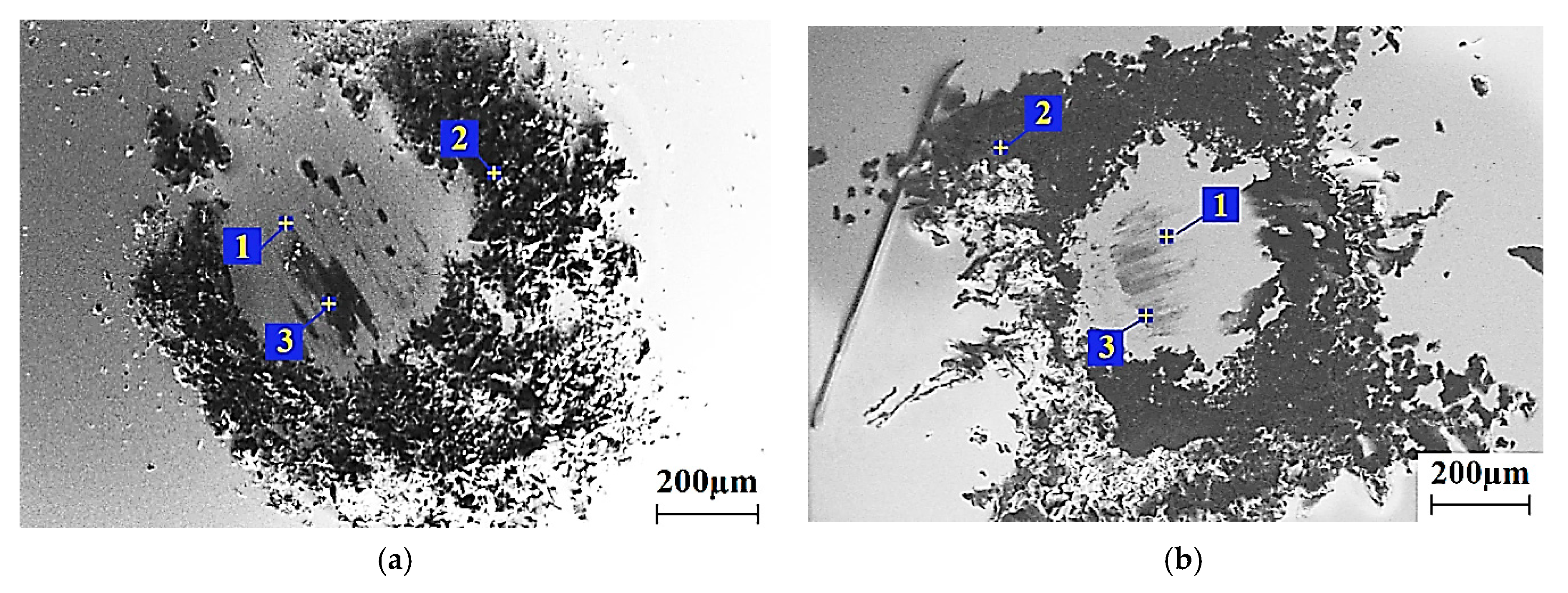
| Element | Spectrum 1 wt%/ at.% | Spectrum 2 wt%/ at.% | Spectrum 3 wt%/ at.% |
|---|---|---|---|
| Steel Counterpart | |||
| Cr | 1.72/1.84 | - | 1.31/0.58 |
| Fe | 98.28/98.16 | 0.69/0.17 | 58.57/23.76 |
| C | - | 75.19/83.05 | 40.08/75.64 |
| F | - | 23.87/16.66 | - |
| Si | - | 0.25/0.12 | - |
| Cu | - | - | 0.04/0.12 |
| Ceramic Counterpart | |||
| Zr | 26.37/4.51 | - | - |
| Fe | - | - | - |
| C | 73.63/95.49- | 67.52/76.68 | 99.35/99.88 |
| F | - | 32.48/23.32 | - |
| Si | - | 0.25/0.12 | - |
| Cu | - | - | 0.65/0.12 |
Publisher’s Note: MDPI stays neutral with regard to jurisdictional claims in published maps and institutional affiliations. |
© 2021 by the authors. Licensee MDPI, Basel, Switzerland. This article is an open access article distributed under the terms and conditions of the Creative Commons Attribution (CC BY) license (http://creativecommons.org/licenses/by/4.0/).
Share and Cite
Panin, S.V.; Nguyen, D.A.; Buslovich, D.G.; Alexenko, V.O.; Pervikov, A.V.; Kornienko, L.A.; Berto, F. Effect of Various Type of Nanoparticles on Mechanical and Tribological Properties of Wear-Resistant PEEK + PTFE-Based Composites. Materials 2021, 14, 1113. https://0-doi-org.brum.beds.ac.uk/10.3390/ma14051113
Panin SV, Nguyen DA, Buslovich DG, Alexenko VO, Pervikov AV, Kornienko LA, Berto F. Effect of Various Type of Nanoparticles on Mechanical and Tribological Properties of Wear-Resistant PEEK + PTFE-Based Composites. Materials. 2021; 14(5):1113. https://0-doi-org.brum.beds.ac.uk/10.3390/ma14051113
Chicago/Turabian StylePanin, Sergey V., Duc A. Nguyen, Dmitry G. Buslovich, Vladislav O. Alexenko, Aleksander V. Pervikov, Lyudmila A. Kornienko, and Filippo Berto. 2021. "Effect of Various Type of Nanoparticles on Mechanical and Tribological Properties of Wear-Resistant PEEK + PTFE-Based Composites" Materials 14, no. 5: 1113. https://0-doi-org.brum.beds.ac.uk/10.3390/ma14051113